Ramesh K. Goel, Joseph R.V. Flora, and J. Paul Chen
CONTENTS
INTRODUCTION
FLOW EQUALIZATION
NEUTRALIZATION
NEUTRALIZATION PRACTICES
pH NEUTRALIZATION PRACTICES
DESIGN OF NEUTRALIZATION SYSTEM
DESIGN EXAMPLES
NOMENCLATURE
REFERENCES
1. INTRODUCTION
Flow equalization and chemical neutralization and are two important components ofwater and wastewater treatment. Chemical neutralization is employed to balance theexcess acidity or alkalinity in water, whereas flow equalization is a process of controllingflow velocity and flow composition. In a practical sense, chemical neutralization is theadjustment of pH to achieve the desired treatment objective. Flow equalization is neces-sary in many municipal and industrial treatment processes to dampen severe variations inflow and water quality. Both these processes have been practiced in the water andwastewater treatment field for several decades. Thtis chapter will present an overview ofthese two processes, the chemistry behind neutralization, design considerations, and theirindustrial application.
2. FLOW EQUALIZATION
Flow equalization is used to minimize the variability of water and wastewaterflow rates and composition. Each unit operation in a treatment train is designed forspecific wastewater characteristics. Improved efficiency and control are possiblewhen all unit operations are carried out at uniform flow conditions. If there exists awide variation in flow composition over time, the treatment efficiency of the overallprocess performance may degrade severely. These variations in flow composition
could be due to many reasons, including the cyclic nature of industrial processes, thesudden occurrence of storm water events, and seasonal variations. To dampen thesevariations, equalization basins are provided at the beginning of the treatment train.The influent water with varying flow composition enters this basin first before it isallowed to go through the rest of the treatment process. Equalization tanks serve manypurposes. Many processes use equalization basins to accumulate and consolidatesmaller volumes of wastewater such that full scale batch reactors can be operated.Other processes incorporate equalization basins in continuous treatment systems toequalize the waste flow so that the effluent at the downstream end can be dischargedat a uniform rate.
Various benefits are ascribed by different investigators to the use of flow equalizationin wastewater treatment systems. Some of the most important benefits are listed asfollows (1–6):
1. Equalization improves sedimentation efficiency by improving hydraulic detention time.2. The efficiency of a biological process can be increased because of uniform flow character-
istics and minimization of the impact of shock loads and toxins during operation.3. Manual and automated control of flow-rate-dependent operations, such as chemical feeding,
disinfection, and sludge pumping, are simplified.4. Treatability of the wastewater is improved and some BOD reduction and odor removal is
provided if aeration is used for mixing in the equalization basin.5. A point of return for recycling concentrated waste streams is provided, thereby mitigating
shock loads to primary settlers or aeration basin.
Sometimes it is thought that equalization tanks also serve the purpose of dilution.However, the United States Environmental Protection Agency (US EPA) does not con-sider the use of equalization tanks as an alternative to achieve dilution. The US EPA’sviewpoint is that dilution is mixing of more concentrated waste with greater volumesof less concentrated waste such that the resulting wastewater does not need any furthertreatment.
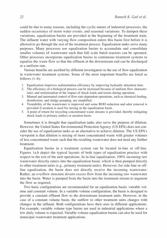
Equalization basins in a treatment system can be located in-line or off-line.Figures 1a,b depict the typical layouts of both types of equalization practice withrespect to the rest of the unit operations. In in-line equalization, 100% incoming rawwastewater directly enters into the equalization basin, which is then pumped directlyto other treatment units (e.g., primary treatment units). However, for side-line or off-line equalization, the basin does not directly receive the incoming wastewater.Rather, an overflow structure diverts excess flow from the incoming raw wastewaterinto the basin. Water is pumped from the basin into the treatment stream to augmentthe flow as required.
Two basic configurations are recommended for an equalization basin: variable vol-ume and constant volume. In a variable volume configuration, the basin is designed toprovide a constant effluent flow to the downstream treatment units. However, in thecase of a constant volume basin, the outflow to other treatment units changes withchanges in the influent. Both configurations have their uses in different applications.For example, variable volume type basins are used in industrial applications where alow daily volume is expected. Variable volume equalization basins can also be used formunicipal wastewater treatment applications.
22 Ramesh K. Goel et al.
02_chap_wang3.qxd 21/01/2005 3:42 pm Page 22
Flow Equalization and Neutralization 23
2.1. Flow Equalization Basin Calculations
Computation of the volume of an equalization basin is the key design requirementand is based on inflow variation over time. There are two methods used to computeequalization volume. One procedure is based on the characteristic diurnal flow pattern,whereas the other is based on the mass loading pattern of a particular constituent.
The first method relies on computing the equalization volume based on the excessdaily average flow storage. The required volume is determined graphically by con-structing a hydrograph. The function of the basin is to store flows in excess of the aver-age daily flow and to divert this flow during times when the inflow is less that theaverage daily flow. The second method computes the volume based on mass loadingvariations within an acceptable range.
In general, the first method is regarded as a flow balance approach and the secondmethod is regarded as a composition balance approach. Flow balance is the most com-mon method for computing equalization basin volume. The selection of a particularmethod depends on the type of flow, flow variations, and overall composition of theflow. Flow balance is used when the composition of incoming water is relatively con-stant but the flow varies over time. The composition balance method is used when therate of inflow is fairly constant and the composition varies with time.
In the flow balance method, a plot of cumulative volume versus time is developed,which is the well-known Rippl diagram (7). The steps required to create a Rippl diagramand to use this diagram to calculate the equalization volume are outlined as follows:
• The first step is to draw a cumulative volume curve based on the wastewater flow. Thevolume that flows within a specified periodic time period is calculated based on the flow.The cumulative volume is obtained by adding the volume at the start of a preselected timeperiod to the volume in the next time period. The resulting volume is then added to the vol-ume in the subsequent time period. This process is continued until a cycle of low-flow andhigh-flow is completed (typically 24 h).
• The second step is to determine the required equalization volume by drawing a line par-allel to the average flow rate and tangent to the cumulative influent flow diagram. Theequalization volume is calculated by the vertical distance from the point of tangency tothe straight line. There could be several points of tangency on the cumulative influentflow curve. However, care should be taken in selecting the points to be taken into con-sideration for equalization volume calculations.
Fig. 1. (a) In-line and (b) off-line flow equalization.
02_chap_wang3.qxd 21/01/2005 3:42 pm Page 23
24 Ramesh K. Goel et al.
The theory behind the method is explained with Fig. 2, which shows a typicalcumulative influent volume curve for the average daily flows. In this figure, thecumulative volume is plotted on the y-axis against the time of day. The resultinggraph is shown by an irregularly shaped curve. If the curve is linear, then the flow isconstant. When the tail end (O) of this cumulative influent volume curve is joinedwith the top end (M), the average flow curve (shown by dotted line) is obtained. Linesparallel to average daily flow line (dotted line) and tangent to mass flow curve arethen drawn. The points of tangency are (B) and (C). From these points of tangency,vertical straight lines are drawn until these vertical lines intersect the average dailyflow line. The points of intersection are given at (A) and (D). The required equalizationvolume will be equal to sum of the vertical distances AB and CD. At the first point (B)of tangency, the storage basin is empty and beyond this point, the basin begins to fill andcontinues until the basin becomes full at upper point (C) of tangency.
The volume calculated based on the hydrograph method is the theoretical volume. Inpractice, the volume will be always greater than the theoretical because of the followingreasons:
• A minimum volume of water is always required in an equalization basin for mixing andaeration equipment inside the basin to operate.
Fig. 2. Volume calculation of equalization basin.
02_chap_wang3.qxd 21/01/2005 3:42 pm Page 24
Flow Equalization and Neutralization 25
• Sometimes, concentrated waste downstream in the treatment plant is returned to the equal-ization basin. To avoid odor problems, dilution of such returned waste is needed and thediluted water is stored in the equalization basin.
• Some free board is always provided to accommodate unforeseen changes in diurnal flow.
Flow equalization is more routinely employed in industry than at municipal facilitiesbecause many industries use batch production processes (2,3). However, there are nowalso a large number of municipal equalization basin installations.
2.2. Mixing and Aeration Requirements
Mixers are often employed in equalization basins to achieve homogeneity in and toaerate the wastewater. Various types of mixers are available. The classification of mixersdepends on the flow pattern the mixers produce. The commonly used mixers have eitheraxial or radial patterns, with axial mixers most prevalently used in industries (8).
Axial mixers can further be subdivided into other categories, the most common ofwhich are propeller mixers and turbine mixers. Propeller mixers are used primarilywhen rapid mixing is needed. The axial propeller mixer can be either fixed or portable,depending on the mixer size and application. The size of top-entering propeller mixersrange from 0.37 to 2.24 kW, although many industrial designs limit the size to 0.75 kWand a maximum shaft length of 1.83 m (8). Propeller mixers are usually mounted angu-larly off center. The advantage with this type of arrangement is that complete top tobottom mixing can be achieved. Typically the maximum water volume that is recom-mended for a propeller mixer is 3.785 m3 (1000 gal). As shown in Fig. 3, the mixer shaftshould enter at 15º from vertical and at a point off the centerline.
The speed ranges for both portable and fixed mounted propeller mixers are 1750 rpmand 350–420 rpm, respectively. The high speed provides a high degree of shear withlow draft velocity, causing instant mixing. Low speeds provide less shear force and mayallow selective setting of larger and heavier particles.
Fig. 3. Illustration of mixer (9).
02_chap_wang3.qxd 21/01/2005 3:42 pm Page 25
26 Ramesh K. Goel et al.
Other classes of axial mixers include turbine mixers. They can induce both axial aswell as radial flow. Axial turbine impellers are pitched blade or fan turbines, whereasradial turbine impellers are flat blade, curved blade, or with a spiral backswept blade(shown in Fig. 4). The curved and spiral backswept impellers are used in high viscousapplications such as sodium hydroxide or soda ash neutralization. Axial turbines areused for large scale mixing involving liquid solid suspensions. Turbines mixers areusually fixed mounted, vertically in fully baffled tanks. Turbine impeller diametersare generally one third of the tank diameter.
2.3. Mixer Unit
The design of an economically feasible mixer unit requires an assessment of powerrequirements, laboratory scale up studies, and the selection of either a batch or contin-uous system, hydraulic retention time, vessel geometry, and type of mixing unit (6). Thefollowing sections discuss some of these design considerations.
2.3.1. Power Requirements
Under turbulent hydraulic conditions (i.e., when the Reynolds number is greater than105), the following formula can be used to determine the power requirements of animpeller mixer (6),
(1)
where P = power requirement, N-m/s, ρ = density of the fluid, kg/m3, KT = constantdependent on impeller size and shape, n = impeller revolutions per second, s−1,D = diameter of impeller, m.
Some of the typical KT values for design purposes are given in Table 1 (6). These KTvalues are for mixing impellers rotating at the center of cylindrical tanks with a flat bot-tom, four baffles at the tank wall, baffle width of 10% of the tank diameter, and impellerdiameter equal to one-third of the tank diameter.
The Camp and Stein mean velocity gradient, G, is used to describe the intensityof mixing in the tank. G is related to the amount of power dissipated in the tank andtypically ranges from 500 to 1500 s−1 for rapid mixing (2). G can be calculated asfollows:
(2)
where V = mixing tank volume, m3, µ = absolute viscocity of the fluid, N-s/m2.To ensure adequate mixing, the tank is sized to obtain a detention time, td, in the
range of 5–30 s for rapid mixing. This results in G × td values of at least 2500, where
(3)
where Q = flow rate, m3/s.
2.3.2. Laboratory Scale Up
The usual practice involves the determination of design parameters in laboratoryscale experiments and then generalizing these parameters for full-scale applications.Problems are often encountered during the scaling up of laboratory parameters for full-scale applications. Careful considerations should be given while selecting designparameters from laboratory experiments. The selection should be based on experience,similarity, and testing accuracy. If budget permits, it is always beneficial to test thedesign parameters found in laboratory experiments and in pilot-scale experiments. Oncethese parameters prove their suitability in pilot-scale experiments, they can further beused for full-scale operations.
Vessel geometry plays a significant role in achieving overall mixing efficiency.However, the selection of vessel geometry is dictated by process considerations. As ageneral rule, circular tanks are more efficient in achieving proper mixing than square orrectangular tanks. For circular tanks, a liquid depth equal to tank diameter is generallyemployed. For tanks less than 4000 L, compact turbine mixers are the most practical.
3. NEUTRALIZATION
Neutralization is a common practice in wastewater treatment and waste stabilization.If a waste stream is found to be hazardous because of corrosivity, neutralization is theprimary treatment used. Moreover, neutralization is used as a pretreatment systembefore a variety of biological, chemical, and physical treatment processes. Since manychemical treatment processes, such as metal precipitation, coagulation, phosphorus pre-cipitation, and water softening are pH dependent, the pH of these processes is adjustedto achieve maximum process efficiency. Furthermore, the pH of the effluent wastewaterfrom different industrial activities also requires adjustment prior to its discharge intoreceiving water bodies. The US EPA has set pH standards for different types of water;for example, the pH range required to protect marine aquatic life is 5–9 (10).
Neutralization is the process of adjusting the pH of water through the addition of anacid or a base, depending on the target pH and process requirements. Some processessuch as boiler operations and drinking water standards need neutral water at a pH of 7.Water or wastewater is generally considered adequately neutralized if (1) its damage tometals, concrete, or other materials is minimal; (2) it has little effect on fish and aquaticlife; (3) it has no effect on biological matter (i.e., biological treatment systems).
In chemical industrial treatment, neutralization of excess alkalinity or acidity is oftenrequired. One of the critical items in neutralizing the water is to determine the nature ofthe substances that cause acidity and alkalinity. This is generally achieved in laboratory-scale experiments by preparing titration curves showing the quantity of alkaline oracidic material necessary to adjust the pH of the target wastewater. The nature oftitration curves obtained in these experiments is critical in determining the properchemical type and dose. Methods used for pH adjustment should be selected on thebasis of costs associated with the neutralizing agent and equipment requirements fordispensing the agent.
In neutralization, several parameters need to be assessed and evaluated before the actualpH adjustment is carried out. These parameters are discussed in the following sections.
3.1. pH
pH is the reference indicator for neutralization. Many chemical processes, such asmetal precipitation and water softening, which are involved in neutralization, are pHdependent. pH is the negative logarithm of the H+ ion activity in solution
(4)
If the ionic strength of the waters is not very high (less than 0.01 M), the activity ofhydrogen ions can be replaced with the molar concentration of hydrogen ions,
pH = log H+− { }
02_chap_wang3.qxd 21/01/2005 3:42 pm Page 28
Flow Equalization and Neutralization 29
If the ionic strength is high, correction factors using the Debye–Hückel equation orDavies equation can be commonly used (10).
In most practical applications, the pH scale ranges from 1 to 14. In pure water and inthe absence of materials other than H+ and OH−, water behaves ideally and activityequals molar concentration. Under these conditions, [H+] equals [OH−] as required byelectroneutrality. At 25ºC, the ion product of water (Kw = [H+][OH−]) is 10−14.
The process of neutralization is not only limited to bringing the pH to 7; it is invariablyused in the processes, where pH adjustment to other than 7 is required depending on thechemical process in question. For example, some processes like biological wastewatertreatment require pH to be near neutral, whereas other processes like metal precipitationrequire pH to be in the alkaline range. Some of the important chemical processes, wherepH plays a significant role and where pH adjustment through neutralization is oftenrequired, are metal adsorption and biosorption, chemical precipitation, water softening,coagulation, water fluoridation, and water oxidation (11–14).
3.2. Acidity and Alkalinity
Alkalinity is the capacity of water to neutralize acids, whereas acidity is the capacityof water to neutralize bases. The amount of acid or base to be used in the neutralizationprocess depends upon the respective amount of acidity and alkalinity.
The most important source of both alkalinity and acidity in natural waters is from thecarbonate system. However, if the wastewater comes from industrial sources, OH− orH+ is also a major contributory factor to alkalinity or acidity, respectively. For example,water from acid mine drainage contains a large amount of acidity because of the pres-ence of sulfuric acid produced from the oxidation of pyrite. Both acidity and alkalinityare expressed in terms of acid/base equivalents. In water and wastewaters where thepredominant ions controlling pH are [H+], [OH−], [HCO3
−], and [CO32−], the forms of
alkalinity encountered are hydroxide, carbonate, and bicarbonate. These three forms ofalkalinity altogether constitute total alkalinity.
Alkalinity and acidity are determined by titration. For wastewater samples whose pH isabove 8.3, titration is made in two steps. In the first step, the pH is brought down to 8.3; inthe second step, the pH is brought down to about 4.5. When the pH of wastewater is below8.3, a single titration curve is made. When the pH of wastewater reaches 8.3, all carbonatepresent in wastewater converts to bicarbonate according to the following reaction;
(5a)
As titration proceeds, bicarbonate goes to carbon dioxide when the pH reaches at 4.5.Carbon dioxide and water together form weak carbonic acid:
(5b)
If it is assumed that carbonate species and OH− are the only chemical constituentscausing alkalinity, the three forms of alkalinity can be defined based on pH. When pHof water is above 8.3, all three forms of alkalinities are present. As a rule of thumb,caustic alkalinity is absent if the pH of the water is below 10, and carbonate alkalinityis absent if the pH is below 8.3.
HCO H H CO3 2 3− ++ →
CO H HCO3 32− + −+ →
02_chap_wang3.qxd 21/01/2005 3:42 pm Page 29
Mathematically, alkalinity can be expressed by considering the volume of acidrequired to drop the pH from or above 10 to 8.3 and then to 4.5. If the initial watercomposition requires Vp mL of acid to reach 8.3 and Vc is the volume of acid requiredto reach pH 4.5, then following holds true (30):
If Vc = 0, alkalinity is due to [OH−] onlyIf Vc = Vp, alkalinity is only due to carbonateIf Vp > Vc, major alkalinity specie are hydroxide and carbonateIf Vp < Vc, major alkalinity species are bicarbonate and carbonates.
In general mathematical terms, the total alkalinity can be expressed using the followingequation:
(6)
The terms on the right-hand side of Eq. (6) are in mol/L. Alternatively, alkalinity can beexpressed in terms of mg/L as CaCO3 (13). Alkalinity of individual species is calculated by
(7)
where EW is the equivalent weight. EW values of CaCO3, CO32−, HCO3
−, OH−, and H+
are 50, 30, 61, 17 and 1, respectively. Therefore Eq. (6) is revised to:
(8)
The terms on the right-hand side of Eq. (8) are in mg/L as CaCO3.The acidity of water is defined in a similar fashion. In the case of acidity also, there
are two equivalence points, one at pH 4.5 and the other at pH 8.3. Depending on the pH,the water can have mineral acidity, CO2 acidity, and total acidity. When pH of the watersample lies below 4.5, the amount of base added to raise the pH to 4.5 is the mineralacidity. In the same way, the amount of base required to raise the solution pH to 8.3 iscalled CO2 acidity. Total acidity corresponds to the amount of base added to raise thepH to the carbonate equivalence point (above 8.3). Mathematically, the total acidity canbe expressed as follows:
(9)
The terms on the right-hand side of Eq. (9) are in mol/L. The ranges of acidity andalkalinity are shown in Fig. 5.
3.3. Buffer Capacity
The word “buffer” stands for the stubbornness against any change. In environmen-tal chemistry, buffers are always defined in the context of pH. pH buffers are thosethat resist any changes in solution pH when an acid or a base is added into the solu-tion. They are very important in chemical neutralization processes. Buffers generallycontain a mixture of weak acid and their salts (conjugate base) or weak bases andtheir conjugate acid. A solution buffered at a particular pH will contain an acid thatcan react with an externally added base and vice versa. The overall efficiency and
Total acidity in eq L = H CO HCO H OH2 3 3+2[ ] + [ ] + [ ] − [ ]− −
Total alkalinity in mg L as CaCO = CO HCO OH H3 3 3+2− − −( ) + ( ) + ( ) − ( )
Alkalinity of species mg L as CaCO species mg L3species
i i
i
EW
EW( ) = ( ) × CaCO3
Total alkalinity in eq L = 2 CO HCO OH H3 3+2− − −[ ] + [ ] + [ ] − [ ]
30 Ramesh K. Goel et al.
02_chap_wang3.qxd 21/01/2005 3:42 pm Page 30
Flow Equalization and Neutralization 31
chemical cost of the neutralization process depend on the presence of pH buffers inwastewaters.
To define the theory behind how pH buffers act, let us take an example. Consider asolution containing 0.06 M acetic acid and 0.06 M sodium acetate. When a smallamount of hydroxide is added in form of sodium hydroxide, the acetic acid present inthe solution ionizes to produce H+, which reacts with the hydroxide added. In similarfashion, if an acid is added to the solution, the acetate takes up the added H+ to formacetic acid.
In natural waters and wastewaters, the buffering capacity arises due to the presenceof phosphates, carbonates, and other weak organic acids. The mineral composition ofnatural waters is regulated by a buffer system involving natural clay minerals such illiteand kaolinite. Careful consideration should be given while neutralizing such waters. Ifthe buffering capacity of the water or wastewater to be neutralized is not taken intoaccount, the actual amount of neutralizing chemical required may vary widely andcauses operational problems.
3.4. Hardness
Hardness in waters arises from the presence of multivalent metallic cations (30). Theprincipal hardness-causing cations are calcium, magnesium, ferrous iron, andmanganous ions. This parameter is important in water-softening processes. The part ofthe total hardness that is chemically equivalent to the bicarbonate plus carbonate alka-linities is called carbonate hardness. When both hardness and alkalinity are expressed inmg/L as CaCO3, these two are be related as follows:When alkalinity < total hardness,
Carbonate hardness (in mg/L) = alkalinity (in mg/L)
When alkalinity > total hardness,
Carbonate hardness (in mg/L) = total hardness (in mg/L)
Fig. 5. Ranges of acidity and alkalinity.
02_chap_wang3.qxd 21/01/2005 3:42 pm Page 31
32 Ramesh K. Goel et al.
4. NEUTRALIZATION PRACTICES
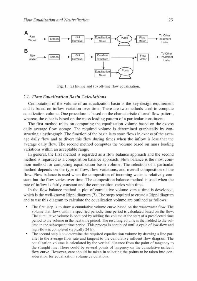
Neutralization can be carried out in either batch or continuous mode. In batch mode,the effluent is retained until its quality meets specifications before release. Several pro-cesses can be simultaneously carried out when the process is performed batchwise.Batch processes are good for small scale treatment plants or small waste volume. Forlarge volumes, a continuous neutralization process is typically used. Figure 6 shows atypical schematic of a continuous neutralization reactor. The use of a batch neutralizingsystem or continuous flow system depends upon several considerations. In general,continuous flow-through systems are used when
• Influent flow is relatively constant and sudden variations are not expected.• The influent flow characteristics are essentially constant.• Effluent chemistry is not very critical. An example is when the process is a part of multi-
stage neutralization process.
Batch neutralization systems are used when:
• There are large fluctuations in influent properties (i.e., flow and pH).• The influent wastewater contains concentrated acids or bases.• The effluent quality has stringent discharge limits.
Neutralization tanks should be constructed with a corrosion-resistant material or shouldbe lined to prevent corrosion. Addition of an acid or an alkali should be controlled by con-tinuous pH measurement, either by withdrawing samples periodically and measuring thepH or by installing an online pH meter that gives continuous pH readings.
4.1. Neutralization of Acidity
The most widely used methods to balance acidity by adding a proper alkaline solutionare outlined below (6):
• Mixing alkaline and acidic wastes such that the net effect is nearly neutral pH.• Passing the acidic water through a limestone bed. This water should not contain lime-
stone-coating substances such as metal salts or sulfuric or hydrofluoric acids.
• Mixing acid waste with lime slurries or dolomitic slurries.• Supplementing acidic wastewater with proper amounts of caustic soda or soda ash (Na2CO3).
Acidic wastes are neutralized either by adding lime alkalis or by adding sodium alkalis.The most commonly used lime alkalis are quicklime (CaO) and hydrated or slaked lime(Ca(OH)2) (13–15). Sodium alkalis involve the use of caustic soda (NaOH) or soda ash(Na2CO3). Calcium and magnesium oxides are considerably less expensive than sodiumalkalis and are used more widely (6). Because these oxides are moderately soluble inwater, they are typically slurried. Calcium or magnesium alkalis produce more sludgethan do sodium alkalis.
Sodium alkali rapidly reacts with acidic wastes and produces soluble neutral saltswhen combined with most acidic wastewaters. Between the two types of sodium alka-lis, caustic soda is a stronger alkali than soda ash. Caustic soda is available in anhydrousform at various concentrations. Soda ash can be purchased as dry granular material.Liquid caustic soda is produced and supplied in a concentration range of 50–73%. Mostindustries use a 50% caustic soda solution. The specific gravity ranges from 1.47 to 1.53depending on the temperature. Caustic soda is very corrosive in nature. Hence all con-tainers and lines that come in to contact with caustic soda during use or shipment shouldbe carefully selected.
Soda ash, when used as sodium carbonate monohydrate, contains 85.48% sodiumcarbonate and 14.52% water of crystallization. Hydrated soda ash loses water of crys-tallization when heated. Heptahydrated and decahydrated are other forms of soda ashused in neutralization practices. Dissolving monohydrated soda ash in water generatesheat while heptahydrate and decahydrate absorbs heat in contact with water. Baggedsoda ash should not be stored in humid places. Furthermore, excessive air circulationshould be avoided. Soda ash contains 99.2% sodium carbonate when shipped.
4.2. Neutralization of Alkalinity
Lowering the pH of a solution is sometimes necessary in some treatment processes orwhen wastewater is to be discharged in open streams. Discharge of effluent with a pHgreater than 8.5 is undesirable and lowering the pH is generally achieved either by addingan acid or by adding carbon dioxide. The process of adding carbon dioxide is called recar-bonation and is often practiced in industrial wastewater neutralization. The commonlyused acids for pH adjustment of alkaline wastewaters are sulfuric acid (H2SO4),hydrochloric acid (HCl), and nitric acid (HNO3). Among them, sulfuric acid is the mostwidely used neutralizing agent. Use of nitric acid is restricted because of more stringentnutrient effluent limitations. There is no direct relationship between pH and alkalinity.Hence, titration curves should be established in laboratories before the design of analkaline wastewater neutralization system. Sulfuric acid used in wastewater treatmentcould be 77.7% concentration or 97% concentration with an approximate specificgravity of 1.83 (1,8,9). Sulfuric acid releases a significant amount of heat when addedto water. Precautionary measures must be taken to avoid any chemical accident due tothe heat generated when practicing neutralization with sulfuric acid. Hydrochloric acidhas an average specific gravity of 1.17 and an acid content of 33% by weight. Properlylined tanks should be used to store this classification of hydrochloric acid. Generallypolyvinyl chloride tanks or lined steel tanks are used.
Flow Equalization and Neutralization 33
02_chap_wang3.qxd 21/01/2005 3:42 pm Page 33
34 Ramesh K. Goel et al.
4.3. Common Neutralization Treatments
The application of neutralization varies from industry to industry. The most commonapplication includes neutralization of acidic waste from mining industries, in chemicalprecipitation, water softening, wastewater coming out from electronic manufacturingplants, and coagulation and flocculation in wastewater-treatment plants. Neutralizationis also required for treated wastewater if the pH of such water is found to be higher orlower than the permissible discharge limits. Some of the applications of neutralizationare discussed in the following sections.
4.3.1. Water Softening
As explained earlier, hardness of water is caused by the presence of polyvalent metalcations. The major disadvantages of using this type of water are the increased consump-tion of soap required to produce lather when bathing or washing clothes and the forma-tion of scales in boilers if this hard water is used for generating steam. Chemicalprecipitation is commonly employed to soften the water, where alkalis are added to thewater to raise the pH and precipitate the metal ions in the forms of hydroxides and car-bonates.
The softened waters usually have high pH values in the range of 10.5 and are super-saturated with calcium carbonate and magnesium hydroxide. For further use of suchhigh pH waters, acid neutralization is applied. Adjustment of pH toward neutrality isaccomplished either by recarbonation or by adding sulfuric acid (30).
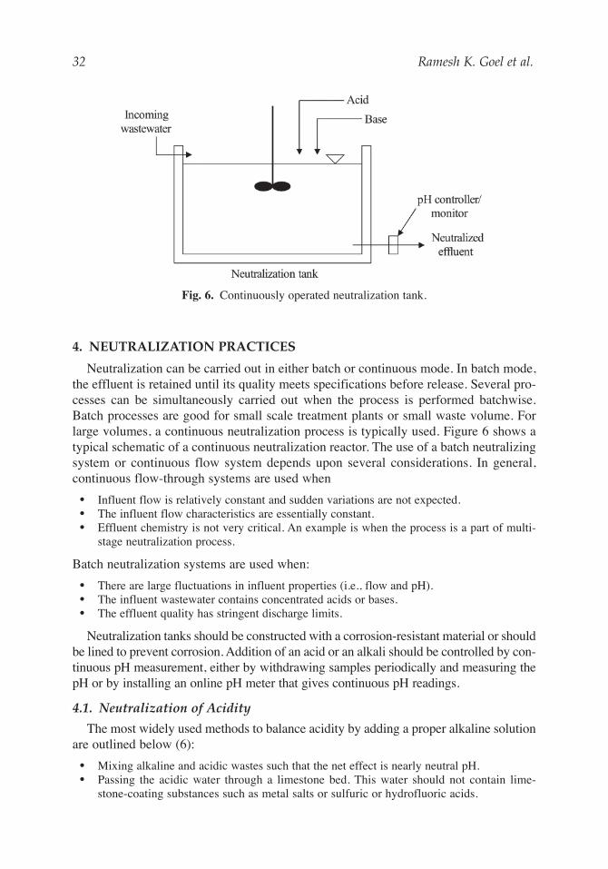
pH adjustment by recarbonation can proceed in two different ways: one-stage recar-bonation or two-stage recarbonation. In one-stage recarbonation, enough CO2 is passedonly one time to drop the pH to the desired level. When sulfuric acid is used in place ofCO2 in one-stage recarbonation, the process is simply called one-stage neutralization. Intwo-stage recarbonation, CO2 is added to water at two different points after excess limetreatment. At the first point of addition, the CO2 is passed to precipitate calcium carbonate.In the next step, CO2 is added to adjust pH to acceptable levels. Figure 7 shows aschematic of one-stage and two-stage recarbonation.
4.3.2. Metal Precipitation
Metal precipitation through formation of metal hydroxide is one of the commonmethods of metal removal in industries. At high pH, most of the metal hydroxides areinsoluble and come out of the solution in the form of metal hydroxide precipitates.Metals are precipitated as the hydroxides through the addition of lime or another baseto raise pH to an optimum value (10–12,30–32). Metal carbonate precipitates can alsobe formed once soluble carbonate solutions such as sodium carbonate are added intometal solutions. Because pH is the most important parameter in precipitation, control ofpH is crucial to the success of the process.
4.3.3. Mine Drainage
The wastewater coming out of mining industries is highly acidic due to the presenceof sulfuric acid in appreciable quantities. Acid water coming out of mining industries isone of the common problems prevalent in United States and around the world. Sulfideminerals, mainly pyrite (FeS2), which are often present in mine waste, can generate acidmine drainage when the waste comes in contact with water and air. Pyrite oxidizes to
02_chap_wang3.qxd 21/01/2005 3:42 pm Page 34
Flow Equalization and Neutralization 35
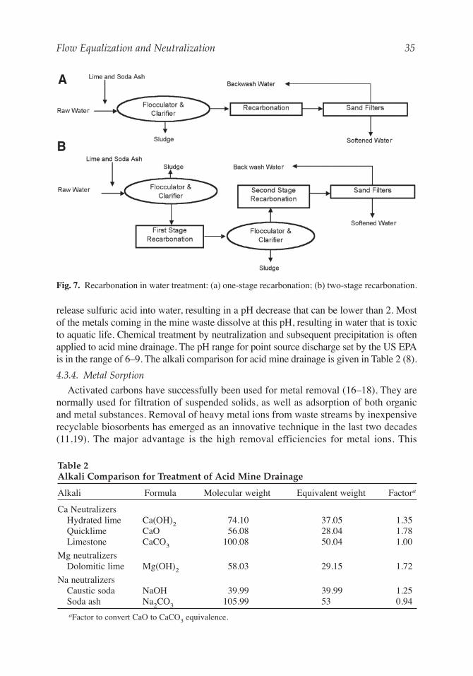
release sulfuric acid into water, resulting in a pH decrease that can be lower than 2. Mostof the metals coming in the mine waste dissolve at this pH, resulting in water that is toxicto aquatic life. Chemical treatment by neutralization and subsequent precipitation is oftenapplied to acid mine drainage. The pH range for point source discharge set by the US EPAis in the range of 6–9. The alkali comparison for acid mine drainage is given in Table 2 (8).
4.3.4. Metal Sorption
Activated carbons have successfully been used for metal removal (16–18). They arenormally used for filtration of suspended solids, as well as adsorption of both organicand metal substances. Removal of heavy metal ions from waste streams by inexpensiverecyclable biosorbents has emerged as an innovative technique in the last two decades(11,19). The major advantage is the high removal efficiencies for metal ions. This
Fig. 7. Recarbonation in water treatment: (a) one-stage recarbonation; (b) two-stage recarbonation.
Table 2Alkali Comparison for Treatment of Acid Mine Drainage
Alkali Formula Molecular weight Equivalent weight Factora
Ca NeutralizersHydrated lime Ca(OH)2 74.10 37.05 1.35Quicklime CaO 56.08 28.04 1.78Limestone CaCO3 100.08 50.04 1.00
Na neutralizersCaustic soda NaOH 39.99 39.99 1.25Soda ash Na2CO3 105.99 53 0.94aFactor to convert CaO to CaCO3 equivalence.
02_chap_wang3.qxd 21/01/2005 3:42 pm Page 35
process is normally termed as biosorption. Normally biodegradation isn’t involved asmost biosorbents are inactive. The term “biosorption” is used simply because thebiosorbents are made from organisms, such as bacteria and seaweed.
Numerous studies have shown that the sorption of metal ions from aqueous solutionsis strongly pH dependent. An increase of the solution pH results in a decrease of positivesurface charge and an increase of negatively charged sites and, eventually, an increaseof metal ion binding. Normally the pH effect becomes less important when the pH isabove 4–6. The metal ion adsorption onto activated carbon increases from 5% to 99%from pH 2.0 to 5.5 (16–18). Sorption experiments using calcium alginate beads (abiosorbent) demonstrated that the metal removal percentages increased from 0 to almost100% (for metal concentrations < 0.1 mM) from pH 1.2 to 4 and a plateau was establishedat a pH > 4 (11). Therefore, neutralization pretreatment must be performed if the initialpH value of metal waste stream is less than 6.
5. pH NEUTRALIZATION PRACTICES
5.1. Passive Neutralization
In most cases, wastewater equalization is used to dampen out short-term extreme pHvariations and allow excess acid to neutralize excess base materials, and vice versa,wherever possible. The equalization can be either on-line or off-line depending on themagnitude of the flows involved.
Off-line equalization is frequently practiced for small flow batch-wise release suchas those associated with the regeneration of a plant’s process water ion exchangecolumns. The isolation and off-line blending of the acid and caustic regenerationstreams allow an industry to minimize the amounts of neutralization agents requiredto produce a wastewater that is suitable for downstream processes. The schematic of atypical industrial neutralization process is shown in Fig. 8.
5.2. In-Plant Neutralization
Industrial facilities that generate a continuous wastewater stream that is consistentlyacidic or basic can practice in-plant neutralization by metering a known quantity of theopposite neutralization agent into the sewer system. The combination of mixing thatoccurs in the pipe lines and in on-site equalization tanks can be sufficient to avoid costlypH adjustment systems.
5.3. Influent pH Neutralization
Industrial wastewaters produced by non-continuous processes that are characterizedto be outside the allowable range for either direct discharge to a treatment plant or on-site treatment must be collected and the pH adjusted with a neutralization system. Themost common influent pH adjustment chemicals are sulfuric acid, carbon dioxide,sodium hydroxide, calcium hydroxide, and magnesium hydroxide.
Carbon dioxide is frequently used as an in-pipe neutralization agent because of itsrapid dissolution rate. The addition rate of the carbon dioxide is controlled by an in-linepH sensor in combination with a proportional pH controller and a wastewater flow meter.
The remaining neutralization agents are normally applied using a flowthroughneutralization tank containing a mechanical agitator capable of providing vigorous
36 Ramesh K. Goel et al.
02_chap_wang3.qxd 21/01/2005 3:42 pm Page 36
Flow Equalization and Neutralization 37
agitation and instantaneous blending of wastewater and the neutralization agent.The neutralization tank contains a pH sensor that is connected to a proportional pHcontroller that sends a control signal to either a neutralization metering pump or con-trol valve that is used to precisely meter the required amount of chemical to meetthe instantaneous demand. These systems operate best when there is a constant (i.e.,pumped) flow rate entering the neutralization tank and upstream equalization is prac-ticed. Variable influent flow rate and a dynamic influent pH range present difficultneutralization problems that increase the complexity and cost of the neutralizationequipment.
If the pH of the influent wastewater is typically more than 2 pH units away from thedesired set point, the system is normally designed with two pH tanks in series. The firsttank is designed to provide a rough pH adjustment and the second provides the fine tuningof the wastewater’s pH.
Typical neutralization tank design provides for a hydraulic residence time between10 and 20 min. The 20-min design factor is normally for systems that use either calciumor magnesium hydroxide slurries for base addition. The additional time is required toallow complete dissolution of the solids and to avoid downstream pH creep associatedwith post-neutralization tank reactions.
In some cases, the influent neutralization system is designed to raise the pH highenough to provide the needed alkalinity for a downstream process such as biologicalnitrification.
5.4. In-Process Neutralization
In well-mixed and buffered biological systems, the designer may elect to practice pHadjustment within the biological system’s aeration basin. Under these circumstances,the designer must be careful to design redundant pH sensors and a control system thatwill protect the bacteria from malfunctioning mechanical or instrumentation systems.
Fig. 8. Industrial neutralization practice.
02_chap_wang3.qxd 21/01/2005 3:42 pm Page 37
Such systems are normally applied where the neutralization agent demand is low andcontinuous in nature such that the addition system can meet the demand but cannotrapidly shift the pH of the system.
5.5. Effluent Neutralization
Effluent neutralization is not normally required for a biological treatment system dis-charging to either a sewage treatment plant or an outfall. Normally, effluent neutralizationwould only be required for a physicochemical treatment system discharging to anNPDES outfall. Effluent neutralization maybe required by a sewage treatment plant ifthe receiving plant has an excess of alkalinity in the influent wastewater. Negotiationscan frequently result in a pretreatment permit that allows discharge of treated wastewaterwith a pH as high as 10 (20,21).
5.6. Chemicals for Neutralization
It may be difficult to hold a pH of 6–8 as a slight change in hydrogen concentrationcan bring about wide swings in pH. Acidic industrial water can be neutralized by slakedlime [also called hydrated lime, calcium hydroxide, Ca(OH)2], caustic soda (sodiumhydroxide, NaOH), and soda ash (sodium carbonate, Na2CO3) (15).
As calcium hydroxide is less expensive than others, it is commonly applied for pHneutralization. High calcium quicklime known as calcium oxide (CaO) anddolomitic quicklime (a mixture of CaO and MgO) are typical commercial limes. Thecomposition is very much dependent on their sources and manufacturing procedures.High calcium quicklime produces a high calcium hydrated lime that contains around70% CaO; a dolomitic hydrate from a dolomitic quicklime has around 45% CaO and34% MgO.
Selection of the above neutralizing agents depends on a series of factors, includingtheir cost, expense of transportation, handling in plant, preparation for usage, andinvestment in facility, storage, safety, and labor costs. Caustic soda is poisonous, thusmust be carefully handled. Emergency eyewashes and showers must be provided closeto the chemical storage and operation area in case of an accident.
Lime may lose its efficiency as the solution pH approaches 7. In addition, the presenceof organics can cause a significant amount of sludge, which is classified as a hazardouswaste and must be treated. Thus, caustic soda as the principal neutralizing agent can beused in order to reduce the sludge production rate (15). However, the operational costwill be increased due to its high purchase expense. Lime can be used first to bring upthe water to a slightly higher pH and subsequently caustic soda can be applied, resultingin the reduction of total operational cost.
Titration experiments are highly recommended to obtain the optimal dosage of neu-tralizing agents. However, if the composition of wastewater is known, one can usecommercially available computer stimulation programs to get the dosage. MINEQL isone of the programs and has been widely used (22). In the program, chemical reac-tions, including solution reactions, precipitation and sorption reactions, in conjunctionwith the mass balances of different species are considered and solved numerically. Ithas been successfully used for many cases, including adsorption of heavy metals andmetal pollution of groundwater (16,23).
38 Ramesh K. Goel et al.
02_chap_wang3.qxd 21/01/2005 3:42 pm Page 38
Flow Equalization and Neutralization 39
5.7. Encapsulated Phosphate Buffers for In Situ Bioremediation
During in situ bioremediation of subsurface sediments and groundwater, changes inpH could be neutralized by the environmentally controlled release into the subsurfaceof phosphate buffers encapsulated in a polymer coating (24,32). The capsules are notdesigned or expected to move through the aquifer to specific contaminated areas.During in situ applications, it is anticipated that the encapsulated buffers would beadded through a series of monitoring wells or drive points at specific locations. Asgroundwater flows through those points, the pH of the groundwater would be modified.This system would be analogous to that of in situ treatment walls in which a reactivebarrier is created through which the groundwater flows. The reactive barrier is notmobile. Once the capsules have been used up, more could be added as necessary andany management of the introduction system, such as de-fouling, could be accomplishedduring that time.
The capsules are designed to release buffer (KH2PO4 or K2HPO4) into sediment porewater as a function of the polymer material used as the outer coating. Polymer coatingscan be designed to dissolve at specific pH levels, releasing the buffer only when neces-sary and mediating not only processes that increase pH, but those that decrease pH aswell.
The KH2PO4 microcapsules designed for application have an average diameter of1 mm and are coated with a polymer that dissolves at pH levels above 7.0. It wasshown that the encapsulated KH2PO4 buffer controlled pH under denitrification con-ditions in activated sludge suspended culture. The pH rise from 7.0 to 8.6 after 2 dof incubation was mediated to 7.0 ± 0.2 pH units in microcosms containing theencapsulated buffer (25).
Encapsulation technology has been examined for in situ bioremediation of subsur-face environments. Vesper et al. encapsulated sodium percarbonate as 0.25–2.0 mmgrains in order to provide a source of oxygen (from hydrogen peroxide) to enhance aer-obic biodegradation of propylene glycol in soil (26). Encapsulated bacteria added to0.2-µm dialysis bags and lowered into contaminated subsurface sediment have beenused to enhance remediation of atrazine (27). dos Santos et al. reported the use of co-immobilized nitrifiers and denitrifiers to remove nitrogen from wastewater systems(28). Lin et al. co-immobilized fungal cells, cellulose co-substrate, and activatedcarbon in alginate beads in order to concentrate pentachlorophenol for microbialdegradation (29). Encapsulation in environmental systems usually entails applica-tions such as these, in which bacteria or slow release compounds are used to directlyenhance biodegradation.
6. DESIGN OF A NEUTRALIZATION SYSTEM
The engineering design of a successful neutralization system involves several steps.Engineering design should be based on several factors such as optimum process param-eters, laboratory-scale tests and their results, and, finally, cost analysis. Practical aspectssuch as availability of neutralizing agent in the near vicinity and thus reduced trans-portation costs play an important role in process design. The important steps involvedin neutralization process design are outlined below.
02_chap_wang3.qxd 21/01/2005 3:42 pm Page 39
All neutralization process, irrespective of type of waste, share several basic featuresand operate on the principle of acid–base reaction. Successful design of a neutralizationprocess should consider the following;
• Influent wastewater parameters• Type of neutralizing agent used• Availability of land• Laboratory scale experimental results
The overall design of neutralization process involves the design of the followingfeatures:
1. Neutralization basin2. Neutralization agent requirements based on theoretical and treatability studies3. Neutralization agent storage (e.g., silo, silo side valve, dust collector, and foundation
7.1. Example 1The flow rate at different time levels is given in Table 3. Calculate the volume of anequalization basin based on the characteristic diurnal flow.
SolutionThe example asks for equalization basin volume based on diurnal flow. Hence, the hydro-graph method described above is used for the calculation. It is assumed that the rate ofinflow between any two consecutive time events is constant. The first step is to calculatethe total volume entering the basin on an hourly basis by multiplying the flow rate ingal/min with 60 min. Then the cumulative flow is calculated as shown in Table 3 with thecorresponding hydrograph shown in Fig. 9.
As explained in the previous section, the equalization volume will be sum of the verticaldistances between the points of tangency of cumulative volume curve and the averagedaily flow. In this example, there are three such vertical distances. In Fig. 9, these dis-tances are shown by AB, CD, and EF. However, close observation reveals that the equal-ization basin starts filling up at point B and continues until the cumulative volume curvereaches at point E. The equalization basin fills up to point C also, and continues beyondthis point until it reaches point E. Hence the equalization volume is given by summationof AB and EF.
Equalization volume = AB + EF = 6000 + 40,000 = 46,000 gal.
7.2. Example 2Design a neutralization basin with 20 min detention time and a complete neutralization sys-tem for an industrial effluent with the following characteristics: flow rate = 0.792 MGD, pH= 3.5, acidity as mg/L CaCO3 = 605, sulfate = 1300 mg/L, suspended solids = 65 mg/L.
Solution
Neutralization basinAssume water depth = 5 ft and detention time period = 20 min:
40 Ramesh K. Goel et al.
02_chap_wang3.qxd 21/01/2005 3:42 pm Page 40
Flow Equalization and Neutralization 41
The neutralization basin can be of square, rectangular, or circular cross section. For asquare basin, each side should be 17.1 ft.
Lime Requirement (Theoretical)Lime requirement will be calculated based on the amount of acidity present in water.Assuming 70% lime efficiency, theoretical lime required is
Theoretical daily lime requirement = 605mg
L
mol Ca(OH)
1.35 mol CaCO
Ca(OH)
2
3
2
× ×
=
1 1
0 7
640
.
mg
L
Surface area required =1470 ft3
5 ftft2= 294
Required volume = 0.792 10d
24 h
h
60 min min
= 11 10 ft
6
3 3
× × × ×
× =
gal
d
gal
1 120
1470
Table 3Wastewater Flow Variation with Time
Time Flow rate (gpm) Total volume (gal) Cumulative volume (gal)
8 AM 70 4200 42009 AM 90 5400 960010 AM 235 14100 2370011 AM 315 18900 4260012 PM 279 16740 593401 PM 142 8520 678602 PM 85 5100 729603 PM 110 6600 795604 PM 78 4680 842405 PM 148 8880 931206 PM 234 14040 1071607 PM 300 18000 1251608 PM 382 22920 1480809 PM 202 12120 16020010 PM 78 4680 16488011 PM 60 3600 16848012 PM 68 4080 1725601 AM 57 3420 1759802 AM 42 2520 1785003 AM 72 4320 1828204 AM 77 4620 1874405 AM 47 2820 1902606 AM 57 3420 1936807 AM 30 1800 195480
02_chap_wang3.qxd 21/01/2005 3:42 pm Page 41
42 Ramesh K. Goel et al.
To assess the actual lime requirement, laboratory-scale titration experiments need to be per-formed. In general, the actual lime requirements are always higher than the theoreticalrequirement, because of other chemicals present. In this particular example, 15% extra isadded to fulfill that requirement:
The above calculation gives a preliminary estimate of the amount of lime to be used.Although it is a good estimate, a treatability study must be performed when designing alarge plant. A firmer estimate of the amount to be purchased on a regular basis will dependon actual usage. Once the amount of lime required is calculated, further design requiresthe selection of the type of lime used. The most common forms of lime used in industriesare quicklime, limestone, and hydrated lime. In this example, quicklime is used, becausethis is the most widely used form of lime:
The actual total quicklime requirement will depend on the average efficiency of the slaker.Let us assume a 90% slaker efficiency:
Actual CaO requirement = 3720lb
d× =1
0 94130
.
lb
d
Quicklime required = 4910lb
d
g quick lime
74 g hydrated lime× =56
3720lb
d
Actual lime requirement = 4270lb
d× =1 15 4910.
lb
d
In terms of lb d , the amount required = 640 mg
L
L
kg
10 mg kg6
× × ×
× × =
0 792 10 3 79
1
0 454270
6. .
.
gal
d gal
lb lb
d
Fig. 9. Hydrograph for volume calculation of equalization basin.
02_chap_wang3.qxd 21/01/2005 3:42 pm Page 42
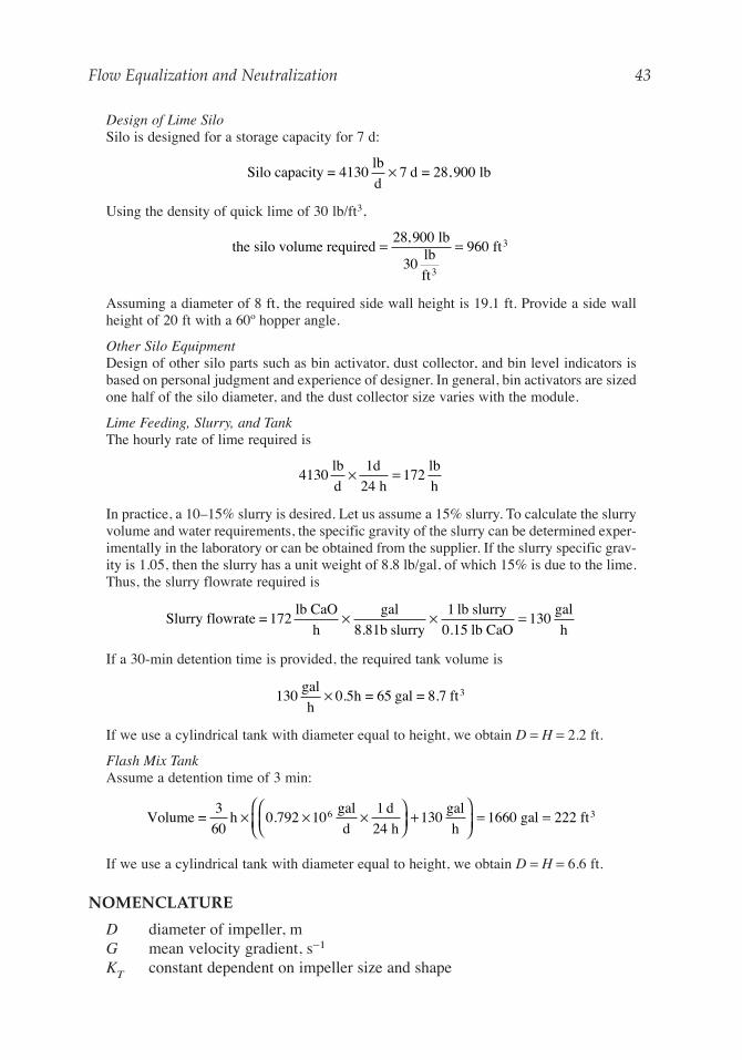
Design of Lime SiloSilo is designed for a storage capacity for 7 d:
Using the density of quick lime of 30 lb/ft3,
Assuming a diameter of 8 ft, the required side wall height is 19.1 ft. Provide a side wallheight of 20 ft with a 60º hopper angle.
Other Silo EquipmentDesign of other silo parts such as bin activator, dust collector, and bin level indicators isbased on personal judgment and experience of designer. In general, bin activators are sizedone half of the silo diameter, and the dust collector size varies with the module.
Lime Feeding, Slurry, and TankThe hourly rate of lime required is
In practice, a 10–15% slurry is desired. Let us assume a 15% slurry. To calculate the slurryvolume and water requirements, the specific gravity of the slurry can be determined exper-imentally in the laboratory or can be obtained from the supplier. If the slurry specific grav-ity is 1.05, then the slurry has a unit weight of 8.8 lb/gal, of which 15% is due to the lime.Thus, the slurry flowrate required is
If a 30-min detention time is provided, the required tank volume is
If we use a cylindrical tank with diameter equal to height, we obtain D = H = 2.2 ft.
Flash Mix TankAssume a detention time of 3 min:
If we use a cylindrical tank with diameter equal to height, we obtain D = H = 6.6 ft.
NOMENCLATURE
D diameter of impeller, mG mean velocity gradient, s−1
KT constant dependent on impeller size and shape
Volume =3
60h
gal
d
1 d
24 h
gal
hgal ft3× × ×
+
= =0 792 10 130 1660 2226.
130 0 5gal
hh = 65 gal = 8.7 ft3× .
Slurry flowrate = 172lb CaO
h
× × =gal
8.81b slurry
1 lb slurry
0.15 lb CaO
gal
h130
4130 172lb
d
1d
24 h
lb
h× =
the silo volume required = =28 900
30960
, lblb
ft
ft
3
3
Silo capacity = 4130lb
dd = 28,900 lb× 7
Flow Equalization and Neutralization 43
02_chap_wang3.qxd 21/01/2005 3:42 pm Page 43
n impeller revolutions per second, s−1
P power requirement, N-m/sQ flow rate, m3/sV mixing tank volume, m3
td detention time, sVp volume of acid added to a solution to reach a pH of 8.3 during titration, mLVc volume of acid added to a solution to reach a pH of 4.5 during titration, mLρ density of the fluid, kg/m3
µ absolute viscocity of the fluid, N-s/m2
REFERENCES
1. US EPA, An Appraisal of Neutralization Processes to Treat Coal Mine Drainage. EPA-670/2-73-093, U.S. Environmental Protection Agency, Washington, DC, 1973.
2. Metcalf & Eddy Inc., Wastewater Engineering: Treatment Disposal Reuse, 4th ed.,McGraw-Hill, New York, 2002.
3. R. A. Corbitt, Wastewater Disposal, McGraw-Hill, New York, 1989.4. E. R. Alley, Water Quality Control Handbook, McGraw-Hill, New York, 2000.5. W. W. J. Eckenfelder, Industrial Water Pollution Control, 3rd ed., McGraw-Hill, New York,
2000.6. WEF/ASCE, Design of Municipal Wastewater Treatment Plants, 4th ed., Water Environment
Federation and American Society of Civil Engineers, 1998.7. US Army Corps of Engineers, Engineering and Design—Hydrologic Engineering
Requirements for Reservoirs, CECW-EH-Y, Washington, DC, 1997.8. US EPA, Design Manual—Neutralization of Acid Mine Drainage, U.S. Environmental
Protection Agency, Municipal Environmental Research Laboratory, EPA-600/2-83-001,U.S. Environmental Protection Agency Technology, Cincinnati, OH, 1983.
9. US EPA, Evaluation of Flow Equalization at a Small Wastewater Treatment Plant, USEnvironmental Protection Agency, Municipal Environmental Research Laboratory, EPA-600/2-76-181, U.S. Environmental Protection Agency, Cincinnati, OH, 1976.
10. W. Stumm and J. J. Morgan, Aquatic Chemistry, John Wiley and Sons, New York, 1981.11. J. P. Chen and L. Wang, Characterization of a Ca-alginate based ion exchange resin and its
applications in lead, copper and zinc removal. Separation Science and Technology, 36(16),3617–3637 (2001).
12. J. P. Chen and H. Yu, Lead removal from synthetic wastewater by crystallization in a fluidized-bed reactor, Journal of Environmental Science and Health, Part A-Toxic/HazardousSubstances & Environmental Engineering, A35(6), 817–835 (2000).
13. M. L. Davis and D. A. Cornwell, Introduction to Environmental Engineering, 3rd ed.,McGraw-Hill, New York, 1998.
14. F. N. Kemmer, The Nalco Water Handbook, McGraw-Hill, New York, 1988.15. C. A. Hazen and J. I. Myers, Neutralization tactics for acidic industrial wastewater. In:
Process Engineering for Pollution Control and Waste Minimization (D. L. Wise, ed.), MarcelDekker, New York, 1994.
16. J. P. Chen and S. N. Wu, Acid/base treated activated carbons: characterization of functionalgroup and metal adsorptive properties, Langmuir, 20(6), 2233–2242 (2004).
17. J. P. Chen and M. S. Lin, Equilibrium and kinetics of metal ion adsorption onto a commercialH-type granular activated carbon: Experimental and modeling Studies, Water Research,35(10), 2385–2394 (2001).
18. J. P. Chen and S. N. Wu, Study on EDTA-chelated copper adsorption by granular activatedcarbon, Journal of Chemical Technology and Biotechnology, 75(9), 791–797 (2000).
44 Ramesh K. Goel et al.
02_chap_wang3.qxd 21/01/2005 3:42 pm Page 44
19. J. P. Chen, L. Hong, S. N. Wu, and L. Wang, Elucidation of interactions between metal ionsand Ca-alginate based ion exchange resin by spectroscopic analysis and modeling simulation,Langmuir, 18(24), 9413–9421 (2002).
20. US EPA, Flow Equalization, EPA 625/4-74-006, US Environmental Protection Agency,Washington DC, 1974.
21. US EPA, Process Design Manual for Upgrading Existing Treatment Plants, EPA 625/1-71-004a, U.S. Environmental Protection Agency, Washington DC 1974.
22. W. D. Schecher and D. C. McAvoy, MINEQL+ Chemical Equilibrium Modeling System,version 4.5 for Windows. Environmental Research Software, Hallowell, ME, 2001.
23. J. P. Chen and S. Yiacoumi, Transport modeling of depleted uranium (DU) in subsurfacesystems, Water, Air, and Soil Pollution, 140(1–4), 173–201 (2002).
24. C. M. Rust, C. M. Aelion, and J. R. V. Flora, Control of pH during denitrification in sub-surface sediment microcosms using an encapsulated phosphate buffer, Water Research,34(5), 1447–1454 (2000).
25. B. Vanukuru, J. R. V. Flora, M. F. Petrou, and C. M. Aelion, Control of pH during denitrifi-cation using an encapsulated phosphate buffer. Water Research, 32(9), 2735–2745 (1998).
26. S. J. Vesper, L. C. Murdoch, S. Hayes, and W. J. Davis-Hoover, Solid oxygen source forbioremediation in subsurface soils. Journal of Hazardous Materials 36(3), 265–274 (1994).
27. M. R. Shati, D. Ronen, and R. Mandelbaum, Method for in situ study of bacterial activityin aquifers. Environmental Science and Technology, 30(8), 2646–2653 (1996).
28. V. A. P. M. dos Santos, M. Bruijnse, J. Tramper, and R. H. Wijffels, The magic-bead concept:an integrated approach to nitrogen removal with co-immobilized micro-organisms. AppliedMicrobiology and Biotechnology, 45(4), 447–453 (1996).
29. J. Lin, H. Y. Wang, and R. F. Hickey, Use of coimmobilized biological systems to degradetoxic organic compounds, Biotechnology and Bioengineering, 38(3), 273–279 (1991).
30. L. K. Wang, Y. T. Hung, and N. S. Shammas (eds.), Physicochemical Treatment Processes.Humana Press, Totowa, NJ (2005).
31. L. K. Wang, N. S. Shammas, and Y. T. Hung (eds.), Advanced Physicochemical TreatmentProcesses. Humana Press, Totowa, NJ (2005).
32. L. K. Wang, Y. T. Hung, H. H. Lo, and C. Yapijakis (eds.), Handbook of Industrial andHazardous Wastes Treatment. Marcel Dekker, Inc., NY, NY. (2004).