Engineering MECHANICS, Vol. 17, 2010, No. 1, p. 3–14 3 FLOW IN THE CROSS-OVER CHANNEL OF A STEAM TURBINE Petr Koˇ c´arn´ ık, Slavom´ ır Jirk˚ u* The document deals with the research of flow in the cross-over channel of the high- pressure stage with partial admission of first stage. In the opening part there is a description of the experimental model and the method of measuring flow fields with high velocity gradient using the stereo PIV principle. The second part describes the design of the model inlet part. The third chapter deals with measuring in the cross- over channel outlet slot with no influence of the stator blade cascade of the following stage. The stator blade cascade feedback is described in the fourth part. During all the measurements we observe the influence of the shaft revolution on the flow field at the cross-over channel outlet. Keywords : cross-over channel, steam turbine, partial admission, blade cascade Nomenclature c velocity, r radial coordinate, α polar coordinate, c ∗ dimensionless velocity, s curvilinear coordinate, α 1 blade cascade exit angle, e degree of admission, x, y rectangular coordinates, ε cross section reduction, q ∗ dimensionless volume flow density, ϕ angle of velocity vector. 1. Introduction The cross-over channel modifies the flow between the first stage of the turbine with partial admission and the following stage with full admission. The aim of the research described below was to experimentally verify the influence of the partial admission, shaft revolution and the stator blade cascade on the uniformity of the following stage admission. An experimental model of the cross-over channel was made for the case of the symmetrical two-slot admission with the partiality degree e =0.3, which corresponds to the slot opening angle of 54 ◦ . The basis for the cross-over channel construction was the high-pressure part drawing of the ˇ Skoda steam turbine. The velocity field measurements were performed using the stereo PIV method. While designing the model we had to respect the dimensions and parameters of the aerodynamic measuring track, workplace technological capabilities and specifications of the PIV measurement method [2], [3]. Construction of the model is obvious from Fig. 1. The model is a modular concept, so it allows us to research more variations of arrangement as well as it enables expected future changes when optimising the arrangement. The model can be divided into two basic parts, i.e. the cross-over channel and the inlet part, which * Ing. P. Koˇ c´arn´ ık, Ph.D., doc. Ing. S. Jirk˚ u,CSc., Czech Technical University in Prague, Faculty of Elec- trical Engineering, Department of Electric Drives and Traction, Technick´a 2, 166 27 Praha 6, Czech Republic
Transcript
Engineering MECHANICS, Vol. 17, 2010, No. 1, p. 3–14 3
FLOW IN THE CROSS-OVER CHANNELOF A STEAM TURBINE
Petr Kocarnık, Slavomır Jirku*
The document deals with the research of flow in the cross-over channel of the high-pressure stage with partial admission of first stage. In the opening part there isa description of the experimental model and the method of measuring flow fields withhigh velocity gradient using the stereo PIV principle. The second part describes thedesign of the model inlet part. The third chapter deals with measuring in the cross-over channel outlet slot with no influence of the stator blade cascade of the followingstage. The stator blade cascade feedback is described in the fourth part. During allthe measurements we observe the influence of the shaft revolution on the flow fieldat the cross-over channel outlet.
c velocity, r radial coordinate, α polar coordinate,c∗ dimensionless velocity, s curvilinear coordinate, α1 blade cascade exit angle,e degree of admission, x, y rectangular coordinates, ε cross section reduction,q∗ dimensionless volume flow density, ϕ angle of velocity vector.
1. Introduction
The cross-over channel modifies the flow between the first stage of the turbine withpartial admission and the following stage with full admission. The aim of the researchdescribed below was to experimentally verify the influence of the partial admission, shaftrevolution and the stator blade cascade on the uniformity of the following stage admission.An experimental model of the cross-over channel was made for the case of the symmetricaltwo-slot admission with the partiality degree e = 0.3, which corresponds to the slot openingangle of 54◦. The basis for the cross-over channel construction was the high-pressure partdrawing of the Skoda steam turbine. The velocity field measurements were performed usingthe stereo PIV method.
While designing the model we had to respect the dimensions and parameters of theaerodynamic measuring track, workplace technological capabilities and specifications of thePIV measurement method [2], [3]. Construction of the model is obvious from Fig. 1. Themodel is a modular concept, so it allows us to research more variations of arrangement aswell as it enables expected future changes when optimising the arrangement. The modelcan be divided into two basic parts, i.e. the cross-over channel and the inlet part, which
* Ing. P. Kocarnık, Ph.D., doc. Ing. S. Jirku, CSc., Czech Technical University in Prague, Faculty of Elec-trical Engineering, Department of Electric Drives and Traction, Technicka 2, 166 27 Praha 6, CzechRepublic
4 Kocarnık P. et al.: Flow in the Cross-Over Channel of a Steam Turbine
Fig.1: Cross-over channel model
Fig.2: Experiment arrangement
transforms the flow from the measuring track circular pipes to the slots supplying the partialadmission. Fig. 2 shows the arrangement of the whole experiment. The inlet part of themodel is connected to the aerodynamic track pipeline via rotary flange. Two rotary pulleyssupport the other side of the part, which allows it to turn round the longitudinal axis. Toachieve required resolution the PIV cameras are not able to scan the motion of particles inthe whole annular slot, but only in its small part (a sector of about 10◦–24◦ according tothe slot size).
Selected arrangement of the experiment enables successive measuring of velocity fieldsin the whole slot when the setting of cameras is fixed. The measuring area can be changedby turning the model, but the adjustment of cameras and laser and calibration of the imagedimensions must be made before the first measurement only. When the measurement isfinished the flow field maps of the whole slot are made up from partial maps using thecomputing algorithm of the Matlab program.
Engineering MECHANICS 5
An electric motor is built in the inlet part area to enable the research on the influence ofshaft revolution on the flow field, see Fig. 1. A carrier is attached to the motor shaft witha collet. The inner wall, supplying a part of the shaft in the cross-over channel, is set onthe carrier. A revolution measuring incremental sensor is built in the clearance behind thecarrier. The electric motor speed regulator is placed outside the model and enables to setrevolutions from 0 to 5000 rpm.
On the outer wall there is a shoulder and a flange enabling attachment of differentmodels of blade cascades to allow us to observe the influence of different blade cascades onthe cross-over channel flow.
2. Inlet part
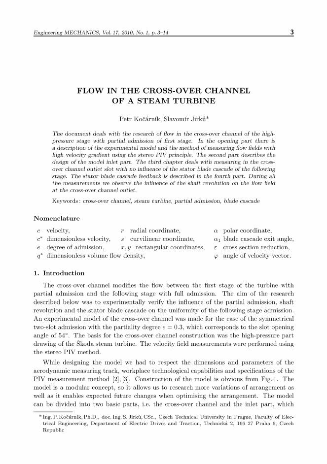
The first step of the model construction was to make an inlet part that suitably transformsthe flow from the circular pipeline to the annular slot. Regarding its influence on the cross-over channel flow we paid much attention to the design. The form of substantial part ofthe axially symmetrical duct was designed using the procedure described in [1] so that themaximum dimensions are not exceeded as well as there are no velocity losses in potentialflow anywhere on the walls. The left part of Fig. 3 shows selected velocity courses in a planarduct and counted courses accordant with the axially symmetrical duct. The right part showsthe final shape of the walls.
Fig.3: Wall shape design based on the velocity distribution
According to Fig. 1 the designed duct was completed with conical part on the inner walland circular passage on the outer wall. Its properties were subsequently verified solving theaxially symmetrical flow field of viscous fluid in the Fluent program.
The inlet velocity and other parameters were selected so that they correspond to thevalues supposed in the experiment. With regard to sufficiently flat course of the outletvelocity profile, the axially symmetrical duct designed in this manner was used as a basisfor further adjustments.
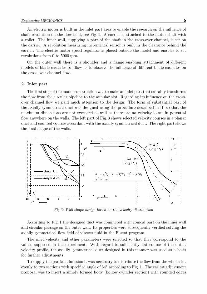
To supply the partial admission it was necessary to distribute the flow from the whole slotevenly to two sections with specified angle of 54◦ according to Fig. 1. The easiest adjustmentproposal was to insert a simply formed body (hollow cylinder section) with rounded edges
6 Kocarnık P. et al.: Flow in the Cross-Over Channel of a Steam Turbine
Fig.4: Flow duct variants
into the straight part of the outlet area. So a duct formed according to Fig. 4, variant A,was created.
A considerable contraction of the cross-section near the outlet indicated unwanted influ-ence on the uniformity of the flow along the outlet slot, which made us change the design tothe variant B shown in Fig. 4, where the primarily inserted body was extended with anotherpart almost reaching the inlet pipe so that the flow distribution into slots is displaced furtherfrom the outlet.
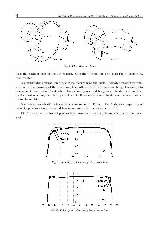
Numerical models of both variants were solved in Fluent. Fig. 5 shows comparison ofvelocity profiles along the radial line in symmetrical plane (angle α = 0◦).
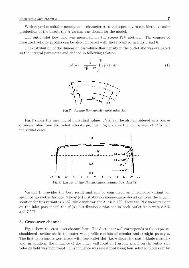
Fig. 6 shows comparison of profiles in a cross section along the middle line of the outletslot.
Fig.5: Velocity profiles along the radial line
Fig.6: Velocity profiles along the middle line
Engineering MECHANICS 7
With regard to suitable aerodynamic characteristics and especially to considerably easierproduction of the insert, the A variant was chosen for the model.
The outlet slot flow field was measured via the stereo PIV method. The courses ofmeasured velocity profiles can be also compared with those counted in Figs. 5 and 6.
The distribution of the dimensionless volume flow density in the outlet slot was evaluatedas the integral parameter and defined in following relation
q∗(α) =2
r2E − r2
I
rE∫rI
c∗2(r) r dr . (1)
Fig.7: Volume flow density determination
Fig. 7 shows the meaning of individual values; q∗(α) can be also considered as a courseof mean value from the radial velocity profiles. Fig. 8 shows the comparison of q∗(α) forindividual cases.
Fig.8: Layout of the dimensionless volume flow density
Variant B provides the best result and can be considered as a reference variant forspecified geometric layouts. The q∗(α) distribution mean-square deviation from the Fluentsolution for this variant is 3.3 %, while with variant A it is 6.7 %. From the PIV measurementon the inlet part model the q∗(α) distribution deviations in both outlet slots were 8.2 %and 7.5 %.
3. Cross-over channel
Fig. 1 shows the cross-over channel form. The duct inner wall corresponds to the stepwise-shouldered turbine shaft; the outer wall profile consists of circular and straight passages.The first experiments were made with free outlet slot (i.e. without the stator blade cascade)and, in addition, the influence of the inner wall rotation (turbine shaft) on the outlet slotvelocity field was monitored. This influence was researched using four selected modes set by
8 Kocarnık P. et al.: Flow in the Cross-Over Channel of a Steam Turbine
the ratio of the inner wall circumferential velocity at the inlet slot (approx. the first-stageblade circumferential velocity) and the inlet slot flow velocity. In the experiments performedthe ratio λ was 0; 0.5; 1 and 1.5 . When the mean inlet velocity was 31 m/s, there were 0,1225, 2550 and 3825 rpm on the inner wall.
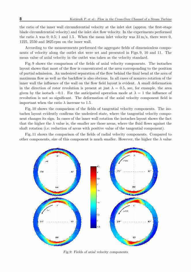
According to the measurements performed the aggregate fields of dimensionless compo-nents of velocity along the outlet slot were set and presented in Figs. 9, 10 and 11. Themean value of axial velocity in the outlet was taken as the velocity standard.
Fig. 9 shows the comparison of the fields of axial velocity components. The isotacheslayout shows that most of the flow is concentrated at the area corresponding to the positionof partial admission. An undesired separation of the flow behind the final bend at the area ofmaximum flow as well as the backflow is also obvious. In all cases of nonzero rotation of theinner wall the influence of the wall on the flow field layout is evident. A small deformationin the direction of rotor revolution is present at just λ = 0.5, see, for example, the areagiven by the isotach −0.1 . For the anticipated operation mode at λ = 1 the influence ofrevolution is not so significant. The deformation of the axial velocity component field isimportant when the ratio λ increase to 1.5 .
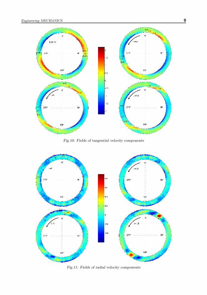
Fig. 10 shows the comparison of the fields of tangential velocity components. The iso-taches layout evidently confirms the undesired state, where the tangential velocity compo-nent changes its sign. In cases of the inner wall rotation the isotaches layout shows the factthat the higher the λ value is, the smaller are those areas, where the fluid flows against theshaft rotation (i.e. reduction of areas with positive value of the tangential component).
Fig. 11 shows the comparison of the fields of radial velocity components. Compared toother components, size of this component is much smaller. However, the higher the λ value
Fig.9: Fields of axial velocity components
Engineering MECHANICS 9
Fig.10: Fields of tangential velocity components
Fig.11: Fields of radial velocity components
10 Kocarnık P. et al.: Flow in the Cross-Over Channel of a Steam Turbine
is, the more deformed is the velocity field. At λ = 1.5 it leads to formation of two remarkable‘focal points’ in the flow field, where the fluid is expelled from the slot in radial directionmore intensively.
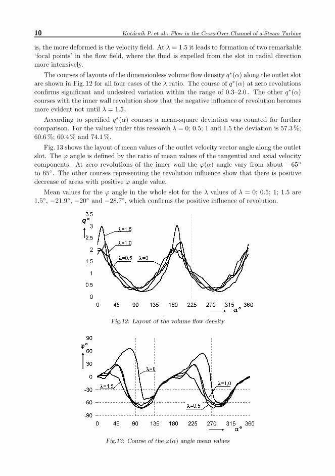
The courses of layouts of the dimensionless volume flow density q∗(α) along the outlet slotare shown in Fig. 12 for all four cases of the λ ratio. The course of q∗(α) at zero revolutionsconfirms significant and undesired variation within the range of 0.3–2.0 . The other q∗(α)courses with the inner wall revolution show that the negative influence of revolution becomesmore evident not until λ = 1.5 .
According to specified q∗(α) courses a mean-square deviation was counted for furthercomparison. For the values under this research λ = 0; 0.5; 1 and 1.5 the deviation is 57.3 %;60.6 %; 60.4 % and 74.1 %.
Fig. 13 shows the layout of mean values of the outlet velocity vector angle along the outletslot. The ϕ angle is defined by the ratio of mean values of the tangential and axial velocitycomponents. At zero revolutions of the inner wall the ϕ(α) angle vary from about −65◦
to 65◦. The other courses representing the revolution influence show that there is positivedecrease of areas with positive ϕ angle value.
Mean values for the ϕ angle in the whole slot for the λ values of λ = 0; 0.5; 1; 1.5 are1.5◦, −21.9◦, −20◦ and −28.7◦, which confirms the positive influence of revolution.
Fig.12: Layout of the volume flow density
Fig.13: Course of the ϕ(α) angle mean values
Engineering MECHANICS 11
4. Blade cascade
The cross-over channel flow is significantly influenced by the existing following stage,which creates continuous resistance for flowing liquid. This resistance causes improvementof uniformity of the cross-over channel outlet flow. Its size is obviously affected by theresistance of the stator blade cascade and can be defined by means ε of reduction of cross-sections of the individual impeller passages. This reduction is defined by the ratio of bladecascade throat width to the blade spacing o/t = sin α1 and the ratio of trailing edge lengthto the leading edge length lo/ln, (see Fig. 14)
ε =loln
sin α1 . (2)
Fig.14: Geometric characteristics of the stator blade cascade
The backward influence of the blade cascade on the cross-over channel flow was researchedin two cases of substitute blade cascade, whose geometric dimensions are shown in Figs. 15and 16.
Fig.15: Substitute blade cascade A Fig.16: Substitute blade cascade B
There are 36 blades in both variants The reduction of the flow duct cross-section forvariant A is ε = 0.55, for variant B it is ε = 0.22 . If the ratio is lo/ln = 0.8, the reductionof the flow duct cross-section corresponds to the outlet angle of α1 = 33◦ in variant A andα1 = 16◦ in variant B for the real blade cascade.
The velocity field in the outlet slot was measured in both variants of the substitute bladecascade. The experiments were made at the same mean velocity in the inlet and for the
12 Kocarnık P. et al.: Flow in the Cross-Over Channel of a Steam Turbine
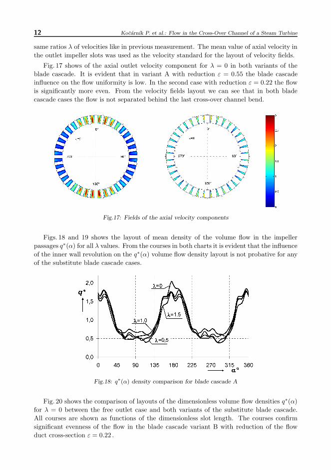
same ratios λ of velocities like in previous measurement. The mean value of axial velocity inthe outlet impeller slots was used as the velocity standard for the layout of velocity fields.
Fig. 17 shows of the axial outlet velocity component for λ = 0 in both variants of theblade cascade. It is evident that in variant A with reduction ε = 0.55 the blade cascadeinfluence on the flow uniformity is low. In the second case with reduction ε = 0.22 the flowis significantly more even. From the velocity fields layout we can see that in both bladecascade cases the flow is not separated behind the last cross-over channel bend.
Fig.17: Fields of the axial velocity components
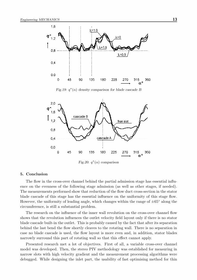
Figs. 18 and 19 shows the layout of mean density of the volume flow in the impellerpassages q∗(α) for all λ values. From the courses in both charts it is evident that the influenceof the inner wall revolution on the q∗(α) volume flow density layout is not probative for anyof the substitute blade cascade cases.
Fig.18: q∗(α) density comparison for blade cascade A
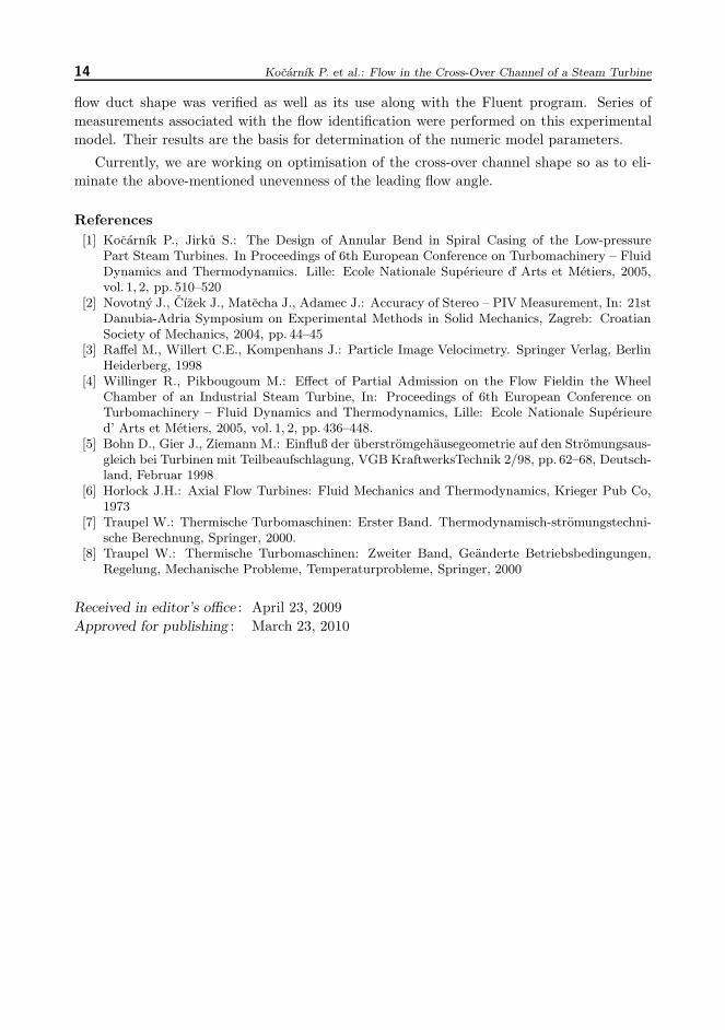
Fig. 20 shows the comparison of layouts of the dimensionless volume flow densities q∗(α)for λ = 0 between the free outlet case and both variants of the substitute blade cascade.All courses are shown as functions of the dimensionless slot length. The courses confirmsignificant evenness of the flow in the blade cascade variant B with reduction of the flowduct cross-section ε = 0.22 .
Engineering MECHANICS 13
Fig.19: q∗(α) density comparison for blade cascade B
Fig.20: q∗(α) comparison
5. Conclusion
The flow in the cross-over channel behind the partial admission stage has essential influ-ence on the evenness of the following stage admission (as well as other stages, if needed).The measurements performed show that reduction of the flow duct cross-section in the statorblade cascade of this stage has the essential influence on the uniformity of this stage flow.However, the uniformity of leading angle, which changes within the range of ±65◦ along thecircumference, is still a substantial problem.
The research on the influence of the inner wall revolution on the cross-over channel flowshows that the revolution influences the outlet velocity field layout only if there is no statorblade cascade built-in the outlet. This is probably caused by the fact that after its separationbehind the last bend the flow shortly cleaves to the rotating wall. There is no separation incase no blade cascade is used, the flow layout is more even and, in addition, stator bladesnarrowly surround this part of rotating wall so that this effect cannot apply.
Presented research met a lot of objectives. First of all, a variable cross-over channelmodel was developed. Then, the stereo PIV methodology was established for measuring innarrow slots with high velocity gradient and the measurement processing algorithms weredebugged. While designing the inlet part, the usability of fast optimising method for thin
14 Kocarnık P. et al.: Flow in the Cross-Over Channel of a Steam Turbine
flow duct shape was verified as well as its use along with the Fluent program. Series ofmeasurements associated with the flow identification were performed on this experimentalmodel. Their results are the basis for determination of the numeric model parameters.
Currently, we are working on optimisation of the cross-over channel shape so as to eli-minate the above-mentioned unevenness of the leading flow angle.
References[1] Kocarnık P., Jirku S.: The Design of Annular Bend in Spiral Casing of the Low-pressure
Part Steam Turbines. In Proceedings of 6th European Conference on Turbomachinery – FluidDynamics and Thermodynamics. Lille: Ecole Nationale Superieure ’d Arts et Metiers, 2005,vol. 1, 2, pp. 510–520
[2] Novotny J., Cızek J., Matecha J., Adamec J.: Accuracy of Stereo – PIV Measurement, In: 21stDanubia-Adria Symposium on Experimental Methods in Solid Mechanics, Zagreb: CroatianSociety of Mechanics, 2004, pp. 44–45
[4] Willinger R., Pikbougoum M.: Effect of Partial Admission on the Flow Fieldin the WheelChamber of an Industrial Steam Turbine, In: Proceedings of 6th European Conference onTurbomachinery – Fluid Dynamics and Thermodynamics, Lille: Ecole Nationale Superieured’ Arts et Metiers, 2005, vol. 1, 2, pp. 436–448.
[5] Bohn D., Gier J., Ziemann M.: Einfluß der uberstromgehausegeometrie auf den Stromungsaus-gleich bei Turbinen mit Teilbeaufschlagung, VGB KraftwerksTechnik 2/98, pp. 62–68, Deutsch-land, Februar 1998