13
CEU 300 Continuing Education from the American Society of Plumbing Engineers Flow in Water Piping October 2021 education.aspe.org

CEU
300
Continuing Education from the American Society of Plumbing Engineers
Flow in Water Piping
October 2021
education.aspe.org

Note: In determining your answers to the CE questions, use only the material presented in the corresponding continuing education article. Using information from other materials may result in a wrong answer.
Flow in Water PipingReprint from Engineered Plumbing Design II, Chapter 11
All rights reserved.
Hydraulics can be defined as the study of the principles and laws that govern the behavior of liquids at rest or in motion. Hydrostatics is the study of liquids at rest and hydrokinetics is the study of liquids in motion.
Although this text deals exclusively with water, all the data developed can be applied to any liquid.
PHYSICAL PROPERTIES OF WATER
The weight of water, or its density, varies with its temperature and purity. Water has its greatest specific weight (weight per cubic foot) at a temperature of 39.2oF. If this phenomenon did not occur, lakes would start freezing from the bottom up instead of from the top down. Table 11-1 tabulates densities of pure water at various temperatures. For the normal range of temperatures met in plumbing systems, the density of water is very close to 62.4 lbm/ft3 and this value can be used for all calculations without any significant error.
TABLE 11-1 Density of Pure Water at Various Temperatures
Temperature °F Density lbm/ft3 Temperature °F Density lbm/ft3
32 62.416 100 61.988
35 62.421 120 61.719
39.2 62.424 140 61.386
40 62.423 160 61.006
50 62.408 180 60.586
60 62.366 200 60.135
70 62.300 212 59.843
80 62.217
Viscosity can be defined as the internal friction, or internal resistance, to the relative motion of fluid particles. It can also be defined as the property by which fluids offer a resistance to a change of shape under the action of an external force. Viscosity varies greatly from one liquid to another. It approaches the conditions of a solid for highly viscous liquids and approaches a gas for the slightly viscous liquids. Viscosity decreases with rising temperatures. For example, # 6 oil is a solid at low temperatures and begins to flow as it is heated.
Water is perfectly elastic, compressing when pressure is imposed and returning to its original condition when the pressure is removed. The compressibility of water may be expressed as 1/K, where K is the coefficient of compressibility and is equal to 43,200,000 lb/ft2. It can be seen that if a pressure of 100 lb/ft2 were applied, the volumetric change would be 100/43,200,000. The change is of such negligible significance that water is always treated as incompressible for all calculations in plumbing design.
The temperature at which water boils varies with the pressure to which it is subjected. At sea level—14.7 psi—water boils at 212°F. At an elevation above sea level, where the atmospheric pressure is less than 14.7 psi, water will boil at a lower temperature. In a closed system, such as that found in the domestic hot water system where the pressure is generally around 50 psi above atmospheric pressure, the water will not boil until a temperature of 300°F is reached.
2 Read, Learn, Earn October 2021
READ, LEARN, EARN: Flow in Water Piping

TYPES OF FLOW
When water is moving in a pipe, two types of flow can exist. One type is known by the various names of streamline, laminar, or viscous. The second is called turbulent flow. At various viscosities (various temperatures), there is a certain critical velocity for every pipe size above which turbulent flow occurs and below which laminar flow occurs. This critical velocity occurs within a range of Reynolds numbers from approximately 2100 to 4000. Reynolds formula is:
(11-1)
Re = DV
gc
where Re = Reynolds number, dimensionless D = Pipe diameter, ft V =Velocityofflow,ft/sec = Density, lbm/ft3 = Dynamic viscosity, lbf · sec/ft2
gc = Gravitational constant, 32.2 lbm·ft/lbf·sec2
Within the limits of accuracy required for plumbing design, it can be assumed that the critical velocity occurs at a Reynolds number of 2100. In laminar flow, the roughness of the pipe wall has a negligible effect on the flow but the viscosity has a very significant effect. In turbulent flow, the viscosity has an insignificant effect but the roughness of the pipe wall has a very marked effect on the flow.
Very rarely is a velocity of less than 4 ft/sec employed in plumbing design. The Reynolds number for a 3 in. pipe and a velocity of flow of 4 ft/sec would be
Re = (0.250ft)(4ft/sec)(62.4lbm/ft3) = 82,500 (2.35 x 10⁻⁵ lbf·sec/ft2)(32.2 lbm·ft/lbf·sec2)
(which is well above the critical number of 2,100)
It can be seen that all plumbing design is with turbulent flow and only when very viscous liquids or extremely low velocities are encountered does the plumbing engineer deal with laminar flow. Critical velocities of 1/2, 1, and 2-in. pipe at 60°F are 0.61, 0.31, and 0.15 ft/sec, respectively, and at 140°F they are 0.25, 0.13, and 0.06 ft/sec, respectively.
VELOCITY OF FLOW
When the velocity of flow is measured across the section of pipe from the center to the wall, it is found that there is a variation in the velocity, with the greatest velocity at the center and a minimum velocity at the walls. The average velocity for the entire cross-section is approximately 84% of the velocity as measured at the center. The plumbing engineer is concerned only with the average velocity, and all formulas are expressed in average velocity. Whenever and wherever the term velocity is used, it is the average velocity of flow that is meant.
Since water is incompressible within the range of pressures met in plumbing design, a definite relationship can be expressed between the quantity flowing past a given point in a given time and the velocity of flow. This can be expressed as (Equation 3-2):
Q = AV
where Q=quantityofflow(flowrate),ft3/sec A=cross-sectionalareaofflow,ft2 V=velocityofflow,ft/sec
The units employed in this flow formula are inconvenient for use in plumbing design. The plumbing engineer deals in gallons per minute and inches for pipe sizes. Converting to these terms, the flow rate becomes (Equation 8-8):
q = 2.448 d2V
where q=quantityofflow(flowrate),gpm d = diameter of pipe, in. V=velocityofflow,ft/sec
3 Read, Learn, Earn October 2021
READ, LEARN, EARN: Flow in Water Piping

POTENTIAL ENERGY
One of the most fundamental laws of thermodynamics is that energy can be neither created nor destroyed; it can only be converted from one form to another. The energy of a body due to its elevation above a given level is called its potential energy in relation to that datum. Work had to be performed to raise the body to that elevation and this work is equal to the product of the weight of the body and the height it was raised. This can be expressed as:
(11-2)
Ep = wh = mgh
gc
where EP = potential energy, ft lbf w = weight of the body, lbf h = height raised, ft m = mass of the body, lbm g = gravitational acceleration, 32.2 ft/s2
gc = gravitational constant, 32.2 lbm·ft/lbf·s2
When the mass (m) is equal to 1 lbm the formula becomes(11-3)
EP = hg gc
where EP = potential energy per pound weight
KINETIC ENERGY
The energy of a body due to its motion is called kinetic energy and is equal to one-half its mass times (or multiplied by) the square of its velocity. Mass is equal to the weight of the body divided by its acceleration imposed by gravity.
(11-4)m = wgc
g
(11-5)
EK = 1/2 x wgc x V2 = w x V2
g gc 2g
where EK = kinetic energy, ft·lbf w = weight of body, lbf m = mass of the body, lbm g = gravitational acceleration, 32.2 ft/sec2
gc = gravitational constant, 32.2 lbm·ft/lbf·sec2
V = velocity, ft/sec
When the body weighs 1 lbf the formula becomes
(11-6)
EK = V2
2gc
where EK = kinetic energy per pound weight
STATIC HEAD
At any point below the surface of water that is exposed to atmospheric pressure, the pressure (head) is produced by the weight of the water above that point. The pressure is equal and effective in all directions at this point and is proportional to the depth below the surface. This pressure is variously called static head, static pressure, hydrostatic head, or hydrostatic pressure. It is the measure of the potential energy. Because pressure is a function of the weight of the water, it is possible to convert the static head expressed as feet of head into pounds per square inch. (See Table 11-2.)
4 Read, Learn, Earn October 2021
READ, LEARN, EARN: Flow in Water Piping
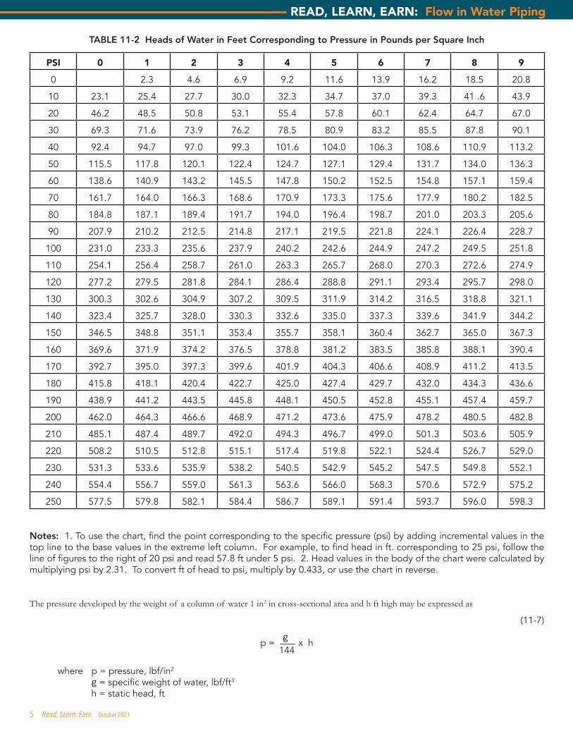
TABLE 11-2 Heads of Water in Feet Corresponding to Pressure in Pounds per Square Inch
PSI 0 1 2 3 4 5 6 7 8 9
0 2.3 4.6 6.9 9.2 11.6 13.9 16.2 18.5 20.8
10 23.1 25.4 27.7 30.0 32.3 34.7 37.0 39.3 41 .6 43.9
20 46.2 48.5 50.8 53.1 55.4 57.8 60.1 62.4 64.7 67.0
30 69.3 71.6 73.9 76.2 78.5 80.9 83.2 85.5 87.8 90.1
40 92.4 94.7 97.0 99.3 101.6 104.0 106.3 108.6 110.9 113.2
50 115.5 117.8 120.1 122.4 124.7 127.1 129.4 131.7 134.0 136.3
60 138.6 140.9 143.2 145.5 147.8 150.2 152.5 154.8 157.1 159.4
70 161.7 164.0 166.3 168.6 170.9 173.3 175.6 177.9 180.2 182.5
80 184.8 187.1 189.4 191.7 194.0 196.4 198.7 201.0 203.3 205.6
90 207.9 210.2 212.5 214.8 217.1 219.5 221.8 224.1 226.4 228.7
100 231.0 233.3 235.6 237.9 240.2 242.6 244.9 247.2 249.5 251.8
110 254.1 256.4 258.7 261.0 263.3 265.7 268.0 270.3 272.6 274.9
120 277.2 279.5 281.8 284.1 286.4 288.8 291.1 293.4 295.7 298.0
130 300.3 302.6 304.9 307.2 309.5 311.9 314.2 316.5 318.8 321.1
140 323.4 325.7 328.0 330.3 332.6 335.0 337.3 339.6 341.9 344.2
150 346.5 348.8 351.1 353.4 355.7 358.1 360.4 362.7 365.0 367.3
160 369.6 371.9 374.2 376.5 378.8 381.2 383.5 385.8 388.1 390.4
170 392.7 395.0 397.3 399.6 401.9 404.3 406.6 408.9 411.2 413.5
180 415.8 418.1 420.4 422.7 425.0 427.4 429.7 432.0 434.3 436.6
190 438.9 441.2 443.5 445.8 448.1 450.5 452.8 455.1 457.4 459.7
200 462.0 464.3 466.6 468.9 471.2 473.6 475.9 478.2 480.5 482.8
210 485.1 487.4 489.7 492.0 494.3 496.7 499.0 501.3 503.6 505.9
220 508.2 510.5 512.8 515.1 517.4 519.8 522.1 524.4 526.7 529.0
230 531.3 533.6 535.9 538.2 540.5 542.9 545.2 547.5 549.8 552.1
240 554.4 556.7 559.0 561.3 563.6 566.0 568.3 570.6 572.9 575.2
250 577.5 579.8 582.1 584.4 586.7 589.1 591.4 593.7 596.0 598.3
Notes:1.Tousethechart,findthepointcorrespondingtothespecificpressure(psi)byaddingincrementalvaluesinthetoplinetothebasevaluesintheextremeleftcolumn.Forexample,tofindheadinft.correspondingto25psi,followthelineoffigurestotherightof20psiandread57.8ftunder5psi.2.Headvaluesinthebodyofthechartwerecalculatedbymultiplying psi by 2.31. To convert ft of head to psi, multiply by 0.433, or use the chart in reverse.
The pressure developed by the weight of a column of water 1 in2 in cross-sectional area and h ft high may be expressed as
(11-7)
p = g x h 144
where p = pressure, lbf/in2 g=specificweightofwater,lbf/ft3 h = static head, ft
5 Read, Learn, Earn October 2021
READ, LEARN, EARN: Flow in Water Piping

At 50°F, the pressure expressed in pounds per square inch for a 1-ft column of water is then:
p = 62.408 x 1 = 0.433 lbf/in2
144
Conversely, the height of a column of water that will impose a pressure of 1 lbf/in2 is
h = p x 144
h = 1 x 144 = 2.31 ft62.408
To convert from feet of head to pounds per square inch, multiply the height by 0.433. To convert pounds per square inch to feet of head, multiply the pounds per square inch by 2.31.
VELOCITY HEAD
In a piping system with the water at rest, the water has potential energy. When the water is flowing it has kinetic energy as well as potential energy. To cause the water to flow some of the available potential energy must be converted to kinetic energy. The decrease in the potential energy, or static head, is called the velocity head.
In a freely falling body, the body is accelerated by the action of gravity at a rate of 32.2 ft/sec2. The height of the fall and the velocity at any moment may be expressed as:
(11-8)
h = gt2
2
(11-9)
V = gt
or t = V g
where h = velocity head, ft t = time, sec g = gravitational acceleration, 32.2 ft/sec2
V = velocity, ft/sec
Substituting t = V/g in the first equation,
h = g
x V2
2 g2
(11-10)
h = V2
2g
The foregoing illustrates the conversion of the potential energy of a body (static head) due to its height into kinetic energy (velocity head). The velocity head, V2/2g, is a measure of the decrease in static head expressed in feet of column of water.
BERNOULLI’S THEOREM
As previously stated, energy can be neither created nor destroyed. Bernoulli developed an equation to express this conservation of energy as it is applied to a flowing liquid. The liquid is assumed to be frictionless and incompressible.
6 Read, Learn, Earn October 2021
READ, LEARN, EARN: Flow in Water Piping

(11-11) Zg + Pgc + V
2 = ET
gc g 2gc
where ET = total energy ft·lbf/lbm Z = height of point above datum, ft P = pressure or head, lb/ ft2 = density, lbm/ft3
V = velocity, ft/sec g = gravitational acceleration, 32.2 ft./sec2
gc = gravitational constant, 32.2 lbm·ft/lbf·sec2
The term Pgc/ g is equal to the static head or height of the liquid column. Substituting in the equation it becomes(11-12)
Zg + h + V2 = ET
gc 2gc
For any two points in a system, we may then write:(11-13)
Z1g + h1 +
V12
= Z2g
+ h2 + V2
2
gc 2gc gc 2gc
Figure 11-1 illustrates the application of this equation.
According to Bernoulli’s theorem of conversion of energy, the energy of a mass particle at one point is equal to its energy at any otherpointinafluidsystem.Intheabsenceoffrictionlosses.
Figure 11-1 Bernoulli’s Theorem (Disregarding Friction)
7 Read, Learn, Earn October 2021
READ, LEARN, EARN: Flow in Water Piping

FRICTION
When water flows in a pipe, friction is produced by the rubbing of water particles against each other and against the walls of the pipe. This friction generates heat, which is dissipated in the form of a rise in the temperature of the water and the piping. This temperature rise in plumbing systems is insignificant and can safely be ignored in plumbing design. It requires a potential energy of 778 ft-lbf to raise 1 lb of water 1°Ft. The friction produced by flowing water also causes a pressure loss along the line of flow, which is called friction head. By utilizing Bernoulli’s equation this friction head loss can be expressed as:
hF = Z1g + h1 +
V12 – Z2g + h2 +
V22
gc 2gc gc 2gc
FLOW FROM OUTLETS
Experiments to determine the velocity of flow from an outlet in the side of an open tank were performed by Toricelli in the 17th century. The result of these experiments was expounded in the theorem: “Except for minor frictional effects, the velocity is the same as if the fluid had fallen freely from the surface through a vertical distance to the outlet.” This can be expressed as:
(11-15)V=√2gh
It is graphically shown in Figure 11-2.
If friction, size, and shape of the opening and entrance losses are disregarded, the ideal velocity is the same as the maximum velocity and is equal to the velocity attained by free fall. The actual velocity, however, is always less than the ideal. All the factors, previously ignored, when taken into consideration can be expressed as the coefficient of discharge, CD. The actual velocity can then be written:
(11-16)V = CD√2gh
For most outlets encountered in a plumbing system an average coefficient of discharge of 0.67 can be safely applied.
Figure 11-2 Toricelli’s Theorem
In the absence of friction, the discharge velocity of a fluidsample moving downward inside tank would equal velocity of a similar sample dropping the same distance outside container. This relationship is based on Toricelli’s theorem.
8 Read, Learn, Earn October 2021
READ, LEARN, EARN: Flow in Water Piping

FLOW IN PIPING
The velocity of flow at any point in a system is due to the total energy at that point. This is the sum of the potential and kinetic energy, less the friction head loss. The static head is the potential energy, but some of it was converted to kinetic energy to cause flow and some of it was used to overcome friction. It is for these reasons that the pressure during flow is always less than the static pressure. The pressure measured at any point while water is flowing is called the flow pressure. This is the pressure that is read on a pressure gauge installed in the piping.
The kinetic energy of water flowing in a plumbing system is extremely small. Very rarely is the design velocity for water flow in plumbing systems greater than 8 ft/sec. The kinetic energy (velocity head) at this velocity is V2/2g or 82/64.4. This is equal to 1 ft or 0.433 psi, which is less than 0.5 psi. It can be seen that such an insignificant pressure can be safely ignored in all calculations. The maximum rate of discharge from an outlet can now be determined from the flow pressure and the diameter of the outlet (using Equations 8-2 to 8-5):
qD = CD q1
qD = CD x 2.448 d2V1
qD = CD x 2.448d2√2gh qD = CD x 19.65d2√hor
(11-17) qD=CDx29.87d2√p
where qD = actual quantity of discharge, gpm q1 = ideal quantity of discharge, gpm CD=coefficientofdischarge,dimensionless d = diameter of outlet, in. V1 = ideal velocity, ft/sec h=flowpressure,ft p=flowpressure,psi
If 0.67 is used for the coefficient of discharge, then, per Equation 6-1,
qD = 13.17d2√hand
(11-18)qD = 20d2√p
FRICTION IN PIPING
As stated previously, whenever flow occurs, there is a continuous loss of pressure along the piping in the direction of flow. The amount of this head loss because of friction is affected by
1. Density and temperature of the fluid 2. Roughness of the pipe 3. Length of run 4. Velocity of the fluid
Experiments have demonstrated that the friction head loss is inversely proportional to the diameter of the pipe, proportional to the roughness and length of the pipe, and varies approximately with the square of the velocity. Darcy expressed this relationship as
h = fLV2 or
D x 2g
(11-19)p = fLV2
144D x 2gc
where h = friction head loss, ft p = friction head loss, lbf/in2 =densityoffluid,lbm/ft3 f=coefficientoffriction,dimensionless L = length of pipe, ft D = diameter of pipe, ft V=velocityofflow,ft/sec gc = gravitational acceleration, 32.2 lbm·ft/lbf·sec2
Values for the coefficient of friction are given in Table 11-3.
9 Read, Learn, Earn October 2021
READ, LEARN, EARN: Flow in Water Piping

It can be seen from Table 11-3 that steel pipe is much rougher than brass, lead or copper. It follows that there will be a greater head loss in steel pipe than in the other material.
TABLE 11-3 Average Values for Coefficient of Friction, f
Nominal Pipe Size, in. Brass, Copper, or Lead Galvanized Iron or Steel
1/2 0.022 0.044
3/4 0.021 0.040
1 0.020 0.038
1 1/4 0.020 0.036
1 1/2½ 0.019 0.035
2 0.018 0.033
2 1/2 0.017 0.031
3 0.017 0.031
4 0.016 0.030
For ease of application for the plumbing engineer, the formula for friction head loss can be reduced to a simpler form. Assuming an average value for the coefficient of friction of 0.02 for brass and copper and 0.04 for steel, the formula becomes:
For brass and copper
(11-20)
h = 0.000623q2 x L d5
(11-21)
p = 0.00027q2 x L d5
and for steel
(11-22)
h = 0.00124q2 x L d5
(11-23)
p = 0.00539q2 x L d5
These formulas can be rearranged in another useful form:
For brass and copper
(11-24)
q = 40.1 d2½ h ½
L(11-25)
q = 60.8 d2½ h ½
L and for steel
(11-26)
q = 28.3 d2½ h ½
L(11-27)
q = 43.0 d2½ h ½
L
10 Read, Learn, Earn October 2021
READ, LEARN, EARN: Flow in Water Piping

where q=quantityofflow,gpm d = diameter of pipe, in. h = pressure, ft p = pressure, psi L = length of pipe, ft
The terms h/L and p/L represent the loss of head due to friction for 1 ft of pipe length and is called the uniform friction loss. Values of d2½ for various diameters of pipe and various materials are given in Table 11-4.
TABLE 11-4 Values of d2½
Nominal Size, In. Brass or Copper Pipe Copper Type K Coper Type L Galvanized Iron or Steel
1/2 0.31 0.20 0.22 0.31
3/4 0.61 0.48 0.55 0.62
1 1.16 0.99 1.06 1.13
1 1/4 2.19 1.73 1.80 2.24
1 1/2 3.24 2.67 2.78 3.29
2 6.17 5.37 5.55 6.14
2 1/2 9.88 9.25 9.54 9.58
3 16.41 14.41 14.87 16.48
4 32.00 29.23 30.13 32.53
In all water flow formulas, the term L (length of run in feet) is always the equivalent length of run (ELR). Every fitting and valve imposes more frictional resistance than the pipe itself. To take this additional friction head loss into account, the fitting or valve is converted to an equivalent length of pipe of the same size that will impose an equal friction loss, e.g., a 4-in. elbow is equivalent to 10 ft of 4-in. pipe. Thus, if the measured length of run of 4-in. piping with one elbow is 15 ft, then the equivalent length of run is 15 + 10 = 25 ft. The length of pipe measured along the centerline of pipe and fittings is the developed length. Table 11-5 shows equivalent lengths of pipe for valves and fittings of various sizes. Note that the larger the pipe size, the more significant the equivalent length of run becomes. In the design phase of piping systems, the size of the piping is not known and the equivalent lengths cannot be accurately determined. A rule of thumb that has worked exceptionally well is to assume 50% of the developed length as an allowance for fittings and valves. Once the sizes are determined, the accuracy of the assumption can be checked.
All equipment imposes a friction head loss and must be carefully considered in the design and operation of a system. The pressure drop through any piece of equipment can be obtained from the manufacturer. The knowledgeable engineer is careful to specify the maximum pressure drop he/she will permit through a piece of equipment.
11 Read, Learn, Earn October 2021
READ, LEARN, EARN: Flow in Water Piping
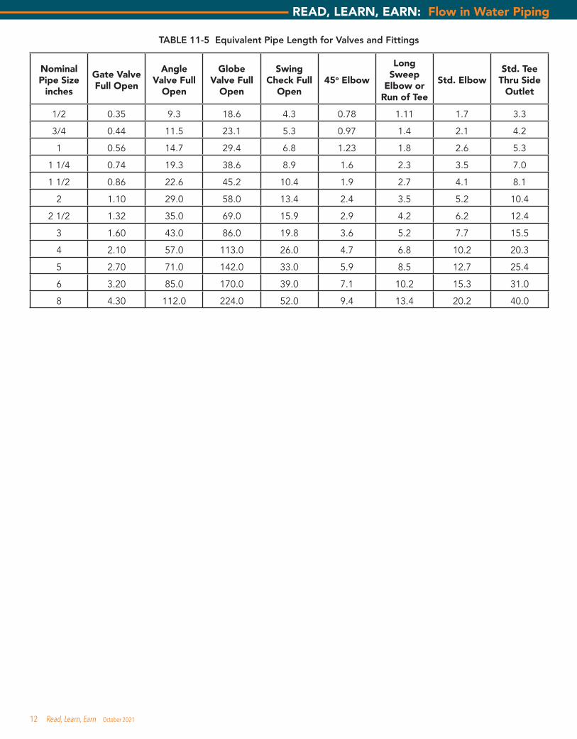
TABLE 11-5 Equivalent Pipe Length for Valves and Fittings
Nominal Pipe Size
inches
Gate Valve Full Open
Angle Valve Full
Open
Globe Valve Full
Open
Swing Check Full
Open45o Elbow
Long Sweep
Elbow or Run of Tee
Std. ElbowStd. Tee
Thru Side Outlet
1/2 0.35 9.3 18.6 4.3 0.78 1.11 1.7 3.3
3/4 0.44 11.5 23.1 5.3 0.97 1.4 2.1 4.2
1 0.56 14.7 29.4 6.8 1.23 1.8 2.6 5.3
1 1/4 0.74 19.3 38.6 8.9 1.6 2.3 3.5 7.0
1 1/2 0.86 22.6 45.2 10.4 1.9 2.7 4.1 8.1
2 1.10 29.0 58.0 13.4 2.4 3.5 5.2 10.4
2 1/2 1.32 35.0 69.0 15.9 2.9 4.2 6.2 12.4
3 1.60 43.0 86.0 19.8 3.6 5.2 7.7 15.5
4 2.10 57.0 113.0 26.0 4.7 6.8 10.2 20.3
5 2.70 71.0 142.0 33.0 5.9 8.5 12.7 25.4
6 3.20 85.0 170.0 39.0 7.1 10.2 15.3 31.0
8 4.30 112.0 224.0 52.0 9.4 13.4 20.2 40.0
12 Read, Learn, Earn October 2021
READ, LEARN, EARN: Flow in Water Piping

ASPE Read, Learn, Earn Continuing EducationYou may submit your answers to the following questions online at aspe.org/ReadLearnEarn. If you score 90 percent or higher on the test, you will be notified that you have earned 0.1 CEU, which can be applied toward CPD or CPDT recertification or numerous regulatory-agency CE programs. (Please note that it is your responsibility to determine the acceptance policy of a particular agency.) CEU information will be kept on file at the ASPE office for three years.
Expiration date: Continuing education credit will be given for this examination through October 31, 2022.
Thank you to J. Francisco DeHoyos, CPD of the Houston and Central Texas Chapters for authoring this month’s quiz.
CE Questions — “Flow in Water Piping” (CEU 300
1. What is the density of pure water at 100°F expressed in lbm/ft3 ? a. 63.416 lbm/ft3
b. 62.4 lbm/ft3
c. 61.719 lbm/ft3
d. 61.988 lbm/ft3
2. What physical property by which fluids offer a resistance to a change of shape under the action of an external force?
a. Density b. Viscosity c. Kinetic energy d. Potential energy
3. At 50°F the height of a column of water that will impose a pressure of 1 lb/in2 is?
a. 0.433 ft b. 1 inch c. 2.31 ft d. 62.4 inches
4. What formula represents the theorem: “Except for minor frictional effects, the velocity is the same as if the fluid had fallen freely from the surface through a vertical distance to the outlet.”
a. V = CD √2gh b. V²/2gc + Zg/gc + Pgc/ g = ET c. h = flV2/Dx2g d. Q = AV
5. What type of energy is equal to one-half its mass and the square of its velocity?
a. Centrifugal b. Kinetic c. Gravitational d. Potential
6. In what stage does the water has potential energy? a. When the water flow is 5ft /sec or faster. b. When the water is flowing less than 5 ft/sec. c. When the water is at rest. d. When the water flow is pressurized.
7. Since water flowing in a pipe generates friction that creates heat, then, what is the potential energy required to raise 1 lb. of water 1°F?
a. 0.433 ft/sec b. 778 ft-lbf c. 8.33 lbs d. 30 inches of mercury
8. Which statement is true about facts about “friction head loss?” a. This occurs at the top of the pipe when it is capped. b. It generates water temperature balance. c. Eliminates water hammering in the pipe system. d. It is inversely proportional to the diameter of the pipe.
9. Which statement is correct about water friction in a pipe? a. Lead pipe is rougher than steel? b. The coefficient friction for 1” copper is 0.038. c. The coefficient friction for 1” steel is 0.020. d. The coefficient friction for 1” copper is 0.020.
10. How can the pressure drop through any piece of equipment can be obtained?
a. Adding values from Tables 11-5 & 11-4 b. Using only the values from Tables 11-4. c. Requesting it from the manufacturer. d. Applying Bernoulli’s equation.
11. Bernoulli developed an equation to express this conservation of energy as it is applied to a flowing liquid. The liquid is assumed to be:
a. Decreasing in static head due to gravity. b. Frictionless and incompressible. c. Pressurized and contained. d. Unpressurized and contained.
12. What is the pressure in PSI at the base of a 6ӯ 80 ft high water riser?
a. 207.78 PSI b. 184.75 PSI c. 34.63 PSI d. 57.62 PSI
13 Read, Learn, Earn October 2021
READ, LEARN, EARN: Flow in Water Piping


