The complete flowmeter system SITRANS FC430 can be or-dered for standard, hygienic or NAMUR service. All versions can be ordered for CT service, according to OIML R 117 (Liquids other than water).
SIL specified compact variants can be validated and configured for SIL 2 or SIL 3 operation. SIL 3 operation requires two flowme-ters in series and monitored by a SIL-rated control system. Se-ries mounting must not introduce cross-talk between the sen-sors. Refer to installation guidelines.
The flowmeter is based on the latest developments within digital signal processing technology – engineered for high measuring performance: • Fast response to rapid changes in flow • Fast dosing applications • High immunity against process noise • High turndown ratio of flowrates • Suitable for liquid and gas service • Easy to install, commission and maintain
FC430 is available as standard with 4 to 20 mA analog output with HART 7.2. Additional functions can be freely configured for analog, pulse, frequency, relay or status output or binary input.
The transmitter comes with a user-configurable graphical dis-play and SensorFlash, a micro SD card for configuration backup, firmware update and data storage.
The SITRANS FC430 flowmeter system consists of a SITRANS FCS400 sensor and a SITRANS FCT030 transmitter.
■ Benefits• It is narrow and light, fitting neatly into dense piping arrange-
ments • Easy maintenance because modules can be exchanged
rapidly • Effective separation of measurement from plant vibration • Highly secure operation in safety critical applications • Non-volatile memory of all setup and operation data • Reliable measurements due to high signal to noise ratio • Secure, digital transfer of measurement data from the sensor • Short overall length; easy drop-in replacement into most exist-
ing installations • Functional Safety (SIL X). Device suitable for use in accor-
• Hygienic threads DIN 11851, DIN 11864-1A, ISO 2853, SMS 1145
• Hygienic clamps DIN 11864-3A, DIN 32676, ISO 2852
Approvals• Hazardous area ATEX, IECEx, FM, NEPSI, CSA,
INMETRO
• Pressure equipment PED, CRN
• Hygienic 3A, EHEDG
• Custody transfer OIML R 117
• Operational safety (compact system only)
SIL 2 Single SIL 3 Redundant system
NAMUR NAMUR-compliant (e.g. NE 21, NE 41 and NE 132)
I/O Up to 4 channels combining ana-log, relay or digital outputs and binary input
Communication HART 7.2
EMC performance EN 61326-3-2
Mechanical load 18 to 400 Hz randomThe flow meter will mechanically tol-erate 3.17 g RMS in all directions. Flow accuracy cannot be guaran-teed under all conditions.
FI01_2015_us_Kap03.book Seite 146 Freitag, 20. Februar 2015 10:20 10
SITRANS FC430 Digital Coriolis flowmeterwith SITRANS FCS400 Standard flow sen-sor with hygienic and flange/pipe thread connections and compact or remote mounting with FCT030 transmitter
7 ME 4 6 1 3 -
77777 - 7777 777
Click on the Article No. for the online con-figuration in the PIA Life Cycle Portal.
Process connectionEN 1092-1 B1, PN 16 A 0EN 1092-1 B1, PN 40 A 1EN 1092-1 B1, PN 63 A 2EN 1092-1 B1, PN 100 A 3EN 1092-1 B1, PN 160 B 1EN 1092-1 D NUT, PN 40 A 5EN 1092-1 D NUT, PN 63 A 6EN 1092-1 D NUT, PN 100 A 7EN 1092-1 D NUT, PN 160 A 8
ANSI B16.5-2009, class 150 D 1ANSI B16.5-2009, class 300 D 2ANSI B16.5-2009, class 600 D 3ANSI B16.5-2009, class 900 D 4
ISO228-1 G pipe thread E 1ASME B1.20.1 NPT pipe thread E 3
DIN 11851 hygienic screwed F 1
DIN 32676 hygienic Tri-Clamp G 1
DIN 11864-1A asceptic screwed H 1DIN 11864-2A asceptic flanged H 2DIN 11864-3A clamped H 3
SMS 1145 hygienic screwed K 112-VCO-4 quick connect K 5JIS B2200:2004/10K L 2JIS B2220:2004/20K L 4JIS B2220:2004/40K L 6JIS B2220:2004/63K L 7
Wetted parts materialAISI 316L/W1.4435/W1.4404 (100 barg max.) 1Hastelloy C22 (only for 7ME461) 3
Calibration/Accuracy class0.1 % flow, 5 kg/m³ density 10.1 % flow, 1 kg/m³ density 4Standard fraction calibration 8
Transmitter/DSL material & mounting styleCompact, IP67, aluminum DRemote, IP67, aluminum, M12 GRemote, IP67, aluminum, T/Box K
Ex approvalNon-Ex AATEX II 2GD CIECEx GDb FFM, Class 1, Div 1 HCSA, Class 1, Zone 1 M
Local User InterfaceBlind 1Graphical, 240 x 160 pxl 3
Selection and Ordering data Order code
Further designsPlease add "-Z" to Article No. and specify Order code(s).
Cable glandsMetric, no glands A01Metric, plastic A02Metric, brass/Ni plated A05Metric, stainless steel A06NPT, no glands A11NPT, Plastic A12NPT, brass/Ni plated A15NPT, stainless steel A16Sofware functions and CT approvalsStandard B11CT standard B31I/O configuration Ch1Ca 4 ... 20 mA HART active SIL certified E04Cp 4 ... 20 mA HART passive SIL certified E05Ca 4 ... 20 mA HART active E06Cp 4 ... 20 mA HART passive E07Only compact versions can be used in SIL applications.
Selection and Ordering data Article No. Ord. code
SITRANS FC430 Digital Coriolis flowmeterwith SITRANS FCS400 Standard flow sen-sor with hygienic and flange/pipe thread connections and compact or remote mounting with FCT030 transmitter
7 ME 4 6 1 3 -
77777 - 7777 777
FI01_2015_us_Kap03.book Seite 147 Freitag, 20. Februar 2015 10:20 10
This device is shipped with a Quick Start guide and a CD containingfurther SITRANS F C literature.
All literature is also available for free at: http://www.siemens.com/flowdocumentation
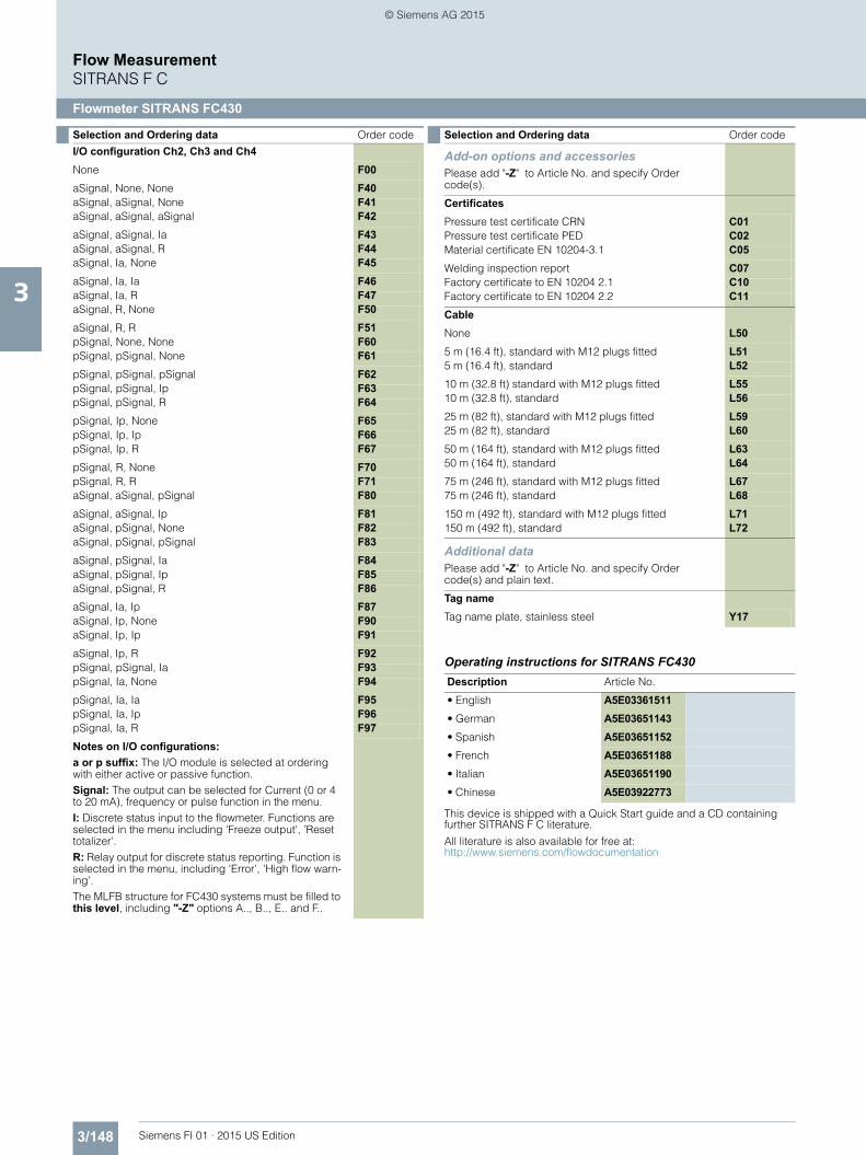
I/O configuration Ch2, Ch3 and Ch4None F00aSignal, None, None F40aSignal, aSignal, None F41aSignal, aSignal, aSignal F42aSignal, aSignal, Ia F43aSignal, aSignal, R F44aSignal, Ia, None F45aSignal, Ia, Ia F46aSignal, Ia, R F47aSignal, R, None F50aSignal, R, R F51pSignal, None, None F60pSignal, pSignal, None F61pSignal, pSignal, pSignal F62pSignal, pSignal, Ip F63pSignal, pSignal, R F64pSignal, Ip, None F65pSignal, Ip, Ip F66pSignal, Ip, R F67pSignal, R, None F70pSignal, R, R F71aSignal, aSignal, pSignal F80aSignal, aSignal, Ip F81aSignal, pSignal, None F82aSignal, pSignal, pSignal F83aSignal, pSignal, Ia F84aSignal, pSignal, Ip F85aSignal, pSignal, R F86aSignal, Ia, Ip F87aSignal, Ip, None F90aSignal, Ip, Ip F91aSignal, Ip, R F92pSignal, pSignal, Ia F93pSignal, Ia, None F94pSignal, Ia, Ia F95pSignal, Ia, Ip F96pSignal, Ia, R F97Notes on I/O configurations:a or p suffix: The I/O module is selected at ordering with either active or passive function. Signal: The output can be selected for Current (0 or 4 to 20 mA), frequency or pulse function in the menu.I: Discrete status input to the flowmeter. Functions are selected in the menu including 'Freeze output', ’Reset totalizer'.R: Relay output for discrete status reporting. Function is selected in the menu, including 'Error', 'High flow warn-ing'.The MLFB structure for FC430 systems must be filled to this level, including "-Z" options A.., B.., E.. and F..
Selection and Ordering data Order code
Add-on options and accessoriesPlease add "-Z" to Article No. and specify Order code(s).
CertificatesPressure test certificate CRN C01Pressure test certificate PED C02Material certificate EN 10204-3.1 C05Welding inspection report C07Factory certificate to EN 10204 2.1 C10Factory certificate to EN 10204 2.2 C11CableNone L505 m (16.4 ft), standard with M12 plugs fitted L515 m (16.4 ft), standard L5210 m (32.8 ft) standard with M12 plugs fitted L5510 m (32.8 ft), standard L5625 m (82 ft), standard with M12 plugs fitted L5925 m (82 ft), standard L6050 m (164 ft), standard with M12 plugs fitted L6350 m (164 ft), standard L6475 m (246 ft), standard with M12 plugs fitted L6775 m (246 ft), standard L68150 m (492 ft), standard with M12 plugs fitted L71150 m (492 ft), standard L72
Additional dataPlease add "-Z" to Article No. and specify Order code(s) and plain text.
Tag nameTag name plate, stainless steel Y17
Description Article No.
• English A5E03361511• German A5E03651143• Spanish A5E03651152• French A5E03651188• Italian A5E03651190• Chinese A5E03922773
Selection and Ordering data Order code
FI01_2015_us_Kap03.book Seite 148 Freitag, 20. Februar 2015 10:20 10
SITRANS FC430 Digital Coriolis flowmeterwith SITRANS FCS400 Flow sensor Hygienic version with Ra < 0.8 m, 3A approved, and compact or remote mount-ing with FCT030 transmitter
7 ME 4 6 2 3 -
77777 - 7777 777
Click on the Article No. for the online con-figuration in the PIA Life Cycle Portal.
This device is shipped with a Quick Start guide and a CD containingfurther SITRANS F C literature.
All literature is also available for free at: http://www.siemens.com/flowdocumentation
I/O configuration Ch2, Ch3 and Ch4None F00aSignal, None, None F40aSignal, aSignal, None F41aSignal, aSignal, aSignal F42aSignal, aSignal, Ia F43aSignal, aSignal, R F44aSignal, Ia, None F45aSignal, Ia, Ia F46aSignal, Ia, R F47aSignal, R, None F50aSignal, R, R F51pSignal, None, None F60pSignal, pSignal, None F61pSignal, pSignal, pSignal F62pSignal, pSignal, Ip F63pSignal, pSignal, R F64pSignal, Ip, None F65pSignal, Ip, Ip F66pSignal, Ip, R F67pSignal, R, None F70pSignal, R, R F71aSignal, aSignal, pSignal F80aSignal, aSignal, Ip F81aSignal, pSignal, None F82aSignal, pSignal, pSignal F83aSignal, pSignal, Ia F84aSignal, pSignal, Ip F85aSignal, pSignal, R F86aSignal, Ia, Ip F87aSignal, Ip, None F90aSignal, Ip, Ip F91aSignal, Ip, R F92pSignal, pSignal, Ia F93pSignal, Ia, None F94pSignal, Ia, Ia F95pSignal, Ia, Ip F96pSignal, Ia, R F97Notes on I/O configurations:a or p suffix: The I/O module is selected at ordering with either active or passive function. Signal: The output can be selected for Current (0 or 4 to 20 mA), frequency or pulse function in the menu.I: Discrete status input to the flowmeter. Functions are selected in the menu including 'Freeze output', ’Reset totalizer'.R: Relay output for discrete status reporting. Function is selected in the menu, including 'Error', 'High flow warn-ing'.The MLFB structure for FC430 systems must be filled to this level, including "-Z" options A.., B.., E.. and F..
Selection and Ordering data Order code
Add-on options and accessoriesPlease add "-Z" to Article No. and specify Order code(s).
CertificatesPressure test certificate CRN C01Pressure test certificate PED C02Material certificate EN 10204-3.1 C05Welding inspection report C07Factory certificate to EN 10204 2.1 C10Factory certificate to EN 10204 2.2 C11CableNone L505 m (16.4 ft), standard with M12 plugs fitted L515 m (16.4 ft), standard L5210 m (32.8 ft) standard with M12 plugs fitted L5510 m (32.8 ft), standard L5625 m (82 ft), standard with M12 plugs fitted L5925 m (82 ft), standard L6050 m (164 ft), standard with M12 plugs fitted L6350 m (164 ft), standard L6475 m (246 ft), standard with M12 plugs fitted L6775 m (246 ft), standard L68150 m (492 ft), standard with M12 plugs fitted L71150 m (492 ft), standard L72
Additional dataPlease add "-Z" to Article No. and specify Order code(s) and plain text.
Tag nameTag name plate, stainless steel Y17
Description Article No.
• English A5E03361511• German A5E03651143• Spanish A5E03651152• French A5E03651188• Italian A5E03651190• Chinese A5E03922773
Selection and Ordering data Order code
FI01_2015_us_Kap03.book Seite 150 Freitag, 20. Februar 2015 10:20 10
SITRANS FC430 Digital Coriolis flowmeterwith SITRANS FCS400 NAMUR complient flow sensor with flange/pipe thread con-nections and compact or remote mount-ing with FCT030 transmitter
7 ME 4 7 1 3 -
77777 - 7777 777
Click on the Article No. for the online con-figuration in the PIA Life Cycle Portal.
Process connectionEN 1092-1 B1, PN 16 A 0EN 1092-1 B1, PN 40 A 1EN 1092-1 B1, PN 63 A 2EN 1092-1 B1, PN 100 A 3EN 1092-1 B1, PN 160 B 1
EN 1092-1 D, PN 40 A 5EN 1092-1 D, PN 63 A 6EN 1092-1 D, PN 100 A 7EN 1092-1 D, PN 160 A 8
ANSI B16.5, RF, class 150 D 1ANSI B16.5, RF, class 300 D 2ANSI B16.5, RF, class 600 D 3ANSI B16.5, RF, class 900 D 4
ISO228-1 G pipe thread E 1ASME B1.20.1 NPT pipe thread E 3
DIN 11851 Hygienic screwed F 1
DIN 32676-C (inch) Hygienic clamped G 1
DIN 11864-1 Hygienic screwed H 1DIN 11864-2A BF-A Hygienic flanged metric H 2DIN 11864-3A Hygienic clamped H 3DIN 11864-2B BF-A Hygienic flanged NPS H 4
SMS 1145 Hygienic screwed K 1Swagelok Quick Connect K 5
JIS B2200/10K L 2JIS B2200/20K L 4JIS B2200/40K L 6JIS B2200/63K L 7
Wetted parts materialAISI 316L/W1.4435/W1.4404 (100 barg max.)
1
Calibration/Accuracy class0.1 % flow, 5 kg/m³ density 10.1 % flow, 1 kg/m³ density 4Standard fraction calibration 8
Transmitter/DSL material & mounting styleCompact, IP67, aluminum DRemote, IP67, aluminum, M12 GRemote, IP67, aluminum, T/Box K
Ex approvalNon-Ex AATEX II 2GD CIECEx GDb FFM, Class 1, Div 1 HCSA, Class 1, Zone 1 M
Local User InterfaceBlind 1Graphical, 240 x 160 pxl 3
Selection and Ordering data Order code
Further designsPlease add "-Z" to Article No. and specify Order code(s).
Cable glandsMetric, no glands A01Metric, plastic A02Metric, brass/Ni plated A05Metric, stainless steel A06NPT, no glands A11NPT, plastic A12NPT, brass/Ni plated A15NPT, stainless steel A16Sofware functions and CT approvalsStandard B11CT standard B31I/O configuration Ch1Ca 4 ... 20 mA HART active, SIL certified E04Cp 4 ... 20 mA HART passive, SIL certified E05Ca 4 ... 20 mA HART active E06Cp 4 ... 20 mA HART passive E07
Selection and Ordering data Article No. Ord. code
SITRANS FC430 Digital Coriolis flowmeterwith SITRANS FCS400 NAMUR complient flow sensor with flange/pipe thread con-nections and compact or remote mount-ing with FCT030 transmitter
7 ME 4 7 1 3 -
77777 - 7777 777
FI01_2015_us_Kap03.book Seite 151 Freitag, 20. Februar 2015 10:20 10
This device is shipped with a Quick Start guide and a CD containingfurther SITRANS F C literature.
All literature is also available for free at: http://www.siemens.com/flowdocumentation
I/O configuration Ch2, Ch3 and Ch4None F00aSignal, None, None F40aSignal, aSignal, None F41aSignal, aSignal, aSignal F42aSignal, aSignal, Ia F43aSignal, aSignal, R F44aSignal, Ia, None F45aSignal, Ia, Ia F46aSignal, Ia, R F47aSignal, R, None F50aSignal, R, R F51pSignal, None, None F60pSignal, pSignal, None F61pSignal, pSignal, pSignal F62pSignal, pSignal, Ip F63pSignal, pSignal, R F64pSignal, Ip, None F65pSignal, Ip, Ip F66pSignal, Ip, R F67pSignal, R, None F70pSignal, R, R F71aSignal, aSignal, pSignal F80aSignal, aSignal, Ip F81aSignal, pSignal, None F82aSignal, pSignal, pSignal F83aSignal, pSignal, Ia F84aSignal, pSignal, Ip F85aSignal, pSignal, R F86aSignal, Ia, Ip F87aSignal, Ip, None F90aSignal, Ip, Ip F91aSignal, Ip, R F92pSignal, pSignal, Ia F93pSignal, Ia, None F94pSignal, Ia, Ia F95pSignal, Ia, Ip F96pSignal, Ia, R F97Notes on I/O configurations:a or p suffix: The I/O module is selected at ordering with either active or passive function. Signal: The output can be selected for Current (0 or 4 to 20 mA), frequency or pulse function in the menu.I: Discrete status input to the flowmeter. Functions are selected in the menu including 'Freeze output', ’Reset totalizer'.R: Relay output for discrete status reporting. Function is selected in the menu, including 'Error', 'High flow warn-ing'.The MLFB structure for FC430 systems must be filled to this level, including "-Z" options A..., B..., E... and F...
Selection and Ordering data Order code
Add-on options and accessoriesPlease add "-Z" to Article No. and specify Order code(s).
CertificatesPressure test certificate CRN C01Pressure test certificate PED C02Material certificate EN 10204-3.1 C05Welding inspection report C07Factory certificate to EN 10204 2.1 C10Factory certificate to EN 10204 2.2 C11CableNone L505 m (16.4 ft), standard with M12 plugs fitted L515 m (16.4 ft), standard L5210 m (32.8 ft) standard with M12 plugs fitted L5510 m (32.8 ft), standard L5625 m (82 ft), standard with M12 plugs fitted L5925 m (82 ft), standard L6050 m (164 ft), standard with M12 plugs fitted L6350 m (164 ft), standard L6475 m (246 ft), standard with M12 plugs fitted L6775 m (246 ft), standard L68150 m (492 ft), standard with M12 plugs fitted L71150 m (492 ft), standard L72
Additional dataPlease add "-Z" to Article No. and specify Order code(s) and plain text.
Tag nameTag name plate, stainless steel Y17
Description Article No.
• English A5E03361511• German A5E03651143• Spanish A5E03651152• French A5E03651188• Italian A5E03651190• Chinese A5E03922773
Selection and Ordering data Order code
FI01_2015_us_Kap03.book Seite 152 Freitag, 20. Februar 2015 10:20 10
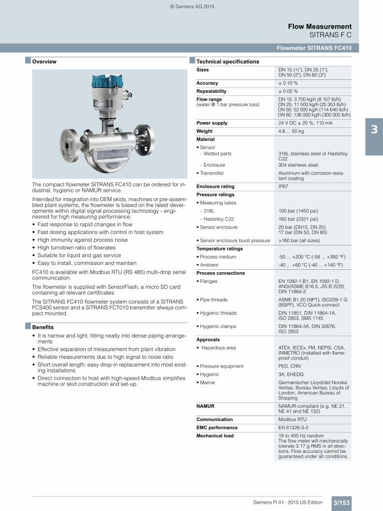
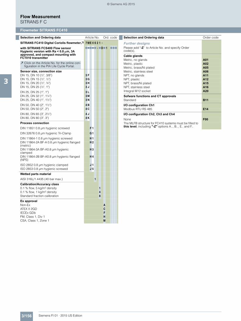
The compact flowmeter SITRANS FC410 can be ordered for in-dustrial, hygienic or NAMUR service.
Intended for integration into OEM skids, machines or pre-assem-bled plant systems, the flowmeter is based on the latest devel-opments within digital signal processing technology - engi-neered for high measuring performance: • Fast response to rapid changes in flow • Fast dosing applications with control in host system • High immunity against process noise • High turndown ratio of flowrates • Suitable for liquid and gas service • Easy to install, commission and maintain
FC410 is available with Modbus RTU (RS 485) multi-drop serial communication.
The flowmeter is supplied with SensorFlash, a micro SD card containing all relevant certificates.
The SITRANS FC410 flowmeter system consists of a SITRANS FCS400 sensor and a SITRANS FCT010 transmitter always com-pact mounted.
■ Benefits• It is narrow and light, fitting neatly into dense piping arrange-
ments • Effective separation of measurement from plant vibration • Reliable measurements due to high signal to noise ratio • Short overall length; easy drop-in replacement into most exist-
ing installations • Direct connection to host with high-speed Modbus simplifies
• Hygienic threads DIN 11851, DIN 11864-1A, ISO 2853, SMS 1145
• Hygienic clamps DIN 11864-3A, DIN 32676, ISO 2852
Approvals• Hazardous area ATEX, IECEx, FM, NEPSI, CSA,
INMETRO (installed with flame-proof conduit)
• Pressure equipment PED, CRN
• Hygienic 3A, EHEDG
• Marine Germanischer Lloyd/det Norske Veritas, Bureau Veritas, Lloyds of London, American Bureau of Shipping
NAMUR NAMUR-compliant (e.g. NE 21, NE 41 and NE 132)
Communication Modbus RTU
EMC performance EN 61326-3-2
Mechanical load 18 to 400 Hz randomThe flow meter will mechanically tolerate 3.17 g RMS in all direc-tions. Flow accuracy cannot be guaranteed under all conditions.
FI01_2015_us_Kap03.book Seite 153 Freitag, 20. Februar 2015 10:20 10
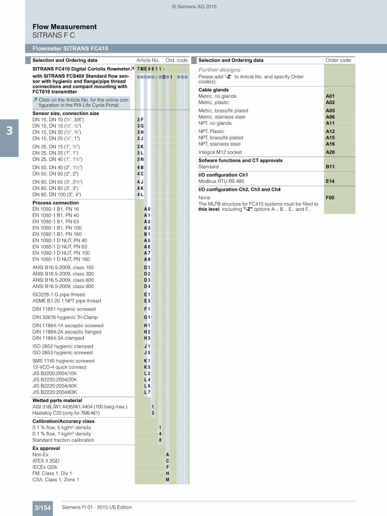
SITRANS FC410 Digital Coriolis flowmeterwith SITRANS FCS400 Standard flow sen-sor with hygienic and flange/pipe thread connections and compact mounting with FCT010 transmitter
7 ME 4 6 1 1 -
77777 - 7D7 1 777
Click on the Article No. for the online con-figuration in the PIA Life Cycle Portal.
Process connectionEN 1092-1 B1, PN 16 A 0EN 1092-1 B1, PN 40 A 1EN 1092-1 B1, PN 63 A 2EN 1092-1 B1, PN 100 A 3EN 1092-1 B1, PN 160 B 1EN 1092-1 D NUT, PN 40 A 5EN 1092-1 D NUT, PN 63 A 6EN 1092-1 D NUT, PN 100 A 7EN 1092-1 D NUT, PN 160 A 8
ANSI B16.5-2009, class 150 D 1ANSI B16.5-2009, class 300 D 2ANSI B16.5-2009, class 600 D 3ANSI B16.5-2009, class 900 D 4
ISO228-1 G pipe thread E 1ASME B1.20.1 NPT pipe thread E 3
DIN 11851 hygienic screwed F 1
DIN 32676 hygienic Tri-Clamp G 1
DIN 11864-1A asceptic screwed H 1DIN 11864-2A asceptic flanged H 2DIN 11864-3A clamped H 3
SMS 1145 hygienic screwed K 112-VCO-4 quick connect K 5JIS B2200:2004/10K L 2JIS B2220:2004/20K L 4JIS B2220:2004/40K L 6JIS B2220:2004/63K L 7
Wetted parts materialAISI 316L/W1.4435/W1.4404 (100 barg max.) 1Hastelloy C22 (only for 7ME461) 3
Calibration/Accuracy class0.1 % flow, 5 kg/m³ density 10.1 % flow, 1 kg/m³ density 4Standard fraction calibration 8
Ex approvalNon-Ex AATEX II 2GD CIECEx GDb FFM, Class 1, Div 1 HCSA, Class 1, Zone 1 M
Selection and Ordering data Order code
Further designsPlease add "-Z" to Article No. and specify Order code(s).
Cable glandsMetric, no glands A01Metric, plastic A02Metric, brass/Ni plated A05Metric, stainless steel A06NPT, no glands A11NPT, Plastic A12NPT, brass/Ni plated A15NPT, stainless steel A16Integral M12 socket A20Sofware functions and CT approvalsStandard B11I/O configuration Ch1Modbus RTU RS 485 E14I/O configuration Ch2, Ch3 and Ch4None F00The MLFB structure for FC410 systems must be filled to this level, including "-Z" options A.., B.., E.. and F..
FI01_2015_us_Kap03.book Seite 154 Freitag, 20. Februar 2015 10:20 10
This device is shipped with a Quick Start guide and a CD containingfurther SITRANS F C literature.
All literature is also available for free at: http://www.siemens.com/flowdocumentation
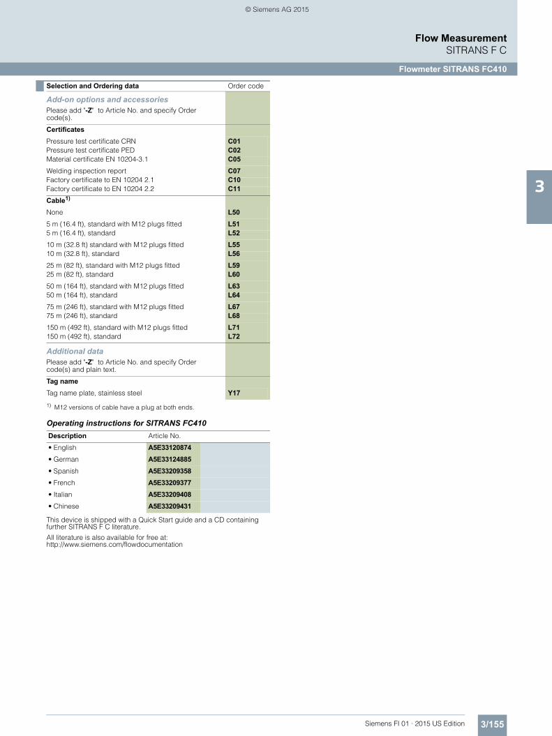
Add-on options and accessoriesPlease add "-Z" to Article No. and specify Order code(s).
CertificatesPressure test certificate CRN C01Pressure test certificate PED C02Material certificate EN 10204-3.1 C05Welding inspection report C07Factory certificate to EN 10204 2.1 C10Factory certificate to EN 10204 2.2 C11Cable1)
None L505 m (16.4 ft), standard with M12 plugs fitted L515 m (16.4 ft), standard L5210 m (32.8 ft) standard with M12 plugs fitted L5510 m (32.8 ft), standard L5625 m (82 ft), standard with M12 plugs fitted L5925 m (82 ft), standard L6050 m (164 ft), standard with M12 plugs fitted L6350 m (164 ft), standard L6475 m (246 ft), standard with M12 plugs fitted L6775 m (246 ft), standard L68150 m (492 ft), standard with M12 plugs fitted L71150 m (492 ft), standard L72
Additional dataPlease add "-Z" to Article No. and specify Order code(s) and plain text.
Tag nameTag name plate, stainless steel Y171) M12 versions of cable have a plug at both ends.
Description Article No.
• English A5E33120874• German A5E33124885• Spanish A5E33209358• French A5E33209377• Italian A5E33209408• Chinese A5E33209431
Selection and Ordering data Order code
FI01_2015_us_Kap03.book Seite 155 Freitag, 20. Februar 2015 10:20 10
SITRANS FC410 Digital Coriolis flowmeterwith SITRANS FCS400 Flow sensor Hygienic version with Ra < 0.8 m, 3A approved, and compact mounting with FCT010 transmitter
7 ME 4 6 2 1 -
77777 - 7D7 1 777
Click on the Article No. for the online con-figuration in the PIA Life Cycle Portal.
Wetted parts materialAISI 316L/1.4435 (40 bar max.) 1
Calibration/Accuracy class0.1 % flow, 5 kg/m³ density 10.1 % flow, 1 kg/m³ density 4Standard fraction calibration 8
Ex approvalNon-Ex AATEX II 2GD CIECEx GDb FFM, Class 1, Div 1 HCSA, Class 1, Zone 1 M
Selection and Ordering data Order code
Further designsPlease add "-Z" to Article No. and specify Order code(s).
Cable glandsMetric, no glands A01Metric, plastic A02Metric, brass/Ni plated A05Metric, stainless steel A06NPT, no glands A11NPT, plastic A12NPT, brass/Ni plated A15NPT, stainless steel A16Integral M12 socket A20Sofware functions and CT approvalsStandard B11I/O configuration Ch1Modbus RTU RS 485 E14I/O configuration Ch2, Ch3 and Ch4None F00The MLFB structure for FC410 systems must be filled to this level, including "-Z" options A.., B.., E.. and F..
FI01_2015_us_Kap03.book Seite 156 Freitag, 20. Februar 2015 10:20 10
This device is shipped with a Quick Start guide and a CD containingfurther SITRANS F C literature.
All literature is also available for free at: http://www.siemens.com/flowdocumentation
Add-on options and accessoriesPlease add "-Z" to Article No. and specify Order code(s).
CertificatesPressure test certificate CRN C01Pressure test certificate PED C02Material certificate EN 10204-3.1 C05Welding inspection report C07Factory certificate to EN 10204 2.1 C10Factory certificate to EN 10204 2.2 C11Cable1)
None L505 m (16.4 ft), standard with M12 plugs fitted L515 m (16.4 ft), standard L5210 m (32.8 ft) standard with M12 plugs fitted L5510 m (32.8 ft), standard L5625 m (82 ft), standard with M12 plugs fitted L5925 m (82 ft), standard L6050 m (164 ft), standard with M12 plugs fitted L6350 m (164 ft), standard L6475 m (246 ft), standard with M12 plugs fitted L6775 m (246 ft), standard L68150 m (492 ft), standard with M12 plugs fitted L71150 m (492 ft), standard L72
Additional dataPlease add "-Z" to Article No. and specify Order code(s) and plain text.
Tag nameTag name plate, stainless steel Y171) M12 versions of cable have a plug at both ends.
Description Article No.
• English A5E33120874• German A5E33124885• Spanish A5E33209358• French A5E33209377• Italian A5E33209408• Chinese A5E33209431
Selection and Ordering data Order code
FI01_2015_us_Kap03.book Seite 157 Freitag, 20. Februar 2015 10:20 10
Process connectionEN1092-1 B1, PN 16 A 0EN1092-1 B1, PN 40 A 1EN1092-1 B1, PN 63 A 2EN1092-1 B1, PN 100 A 3EN1092-1 B1, PN 160 B 1
EN1092-1 D, PN 40 A 5EN1092-1 D, PN 63 A 6EN1092-1 D, PN 100 A 7EN1092-1 D, PN 160 A 8
ANSI B16.5, RF, class 150 D 1ANSI B16.5, RF, class 300 D 2ANSI B16.5, RF, class 600 D 3ANSI B16.5, RF, class 900 D 4
ISO228-1 G pipe thread E 1ASME B1.20.1 NPT pipe thread E 3
DIN 11851 Hygienic screwed F 1
DIN 32676-C (inch) Hygienic clamped G 1
DIN 11864-1 Hygienic screwed H 1DIN 11864-2A BF-A Hygienic flanged metric H 2DIN 11864-3A Hygienic clamped H 3DIN 11864-2B BF-A Hygienic flanged NPS H 4
SMS 1145 Hygienic screwed K 1Swagelok Quick Connect K 5
JIS B2200/10K L 2JIS B2200/20K L 4JIS B2200/40K L 6JIS B2200/63K L 7
Wetted parts materialAISI 316L/W1.4435/W1.4404 (100 barg max.) 1
Calibration/Accuracy class0.1 % flow, 5 kg/m³ density 10.1 % flow, 1 kg/m³ density 4Standard fraction calibration 8
Ex approvalNon-Ex AATEX II 2GD CIECEx GDb FFM, Class 1, Div 1 HCSA, Class 1, Zone 1 M
Selection and Ordering data Order code
Further designsPlease add "-Z" to Article No. and specify Order code(s).
Cable glandsMetric, no glands A01Metric, plastic A02Metric, brass/Ni plated A05Metric, stainless steel A06NPT, no glands A11NPT, plastic A12NPT, brass/Ni plated A15NPT, stainless steel A16Sofware functions and CT approvalsStandard B11I/O configuration Ch1Modbus RTU RS 485 E14I/O configuration Ch2, Ch3 and Ch4None F00The MLFB structure for FC410 systems must be filled to this level, including "-Z" options A..., B..., E... and F...
FI01_2015_us_Kap03.book Seite 158 Freitag, 20. Februar 2015 10:20 10
This device is shipped with a Quick Start guide and a CD containingfurther SITRANS F C literature.
All literature is also available for free at: http://www.siemens.com/flowdocumentation
Add-on options and accessoriesPlease add "-Z" to Article No. and specify Order code(s).
CertificatesPressure test certificate CRN C01Pressure test certificate PED C02Material certificate EN 10204-3.1 C05Welding inspection report C07Factory certificate to EN 10204 2.1 C10Factory certificate to EN 10204 2.2 C11Cable1)
None L505 m (16.4 ft), standard with M12 plugs fitted L515 m (16.4 ft), standard L5210 m (32.8 ft) standard with M12 plugs fitted L5510 m (32.8 ft), standard L5625 m (82 ft), standard with M12 plugs fitted L5925 m (82 ft), standard L6050 m (164 ft), standard with M12 plugs fitted L6350 m (164 ft), standard L6475 m (246 ft), standard with M12 plugs fitted L6775 m (246 ft), standard L68150 m (492 ft), standard with M12 plugs fitted L71150 m (492 ft), standard L72
Additional dataPlease add "-Z" to Article No. and specify Order code(s) and plain text.
Tag nameTag name plate, stainless steel Y171) M12 versions of cable have a plug at both ends.
Description Article No.
• English A5E33120874• German A5E33124885• Spanish A5E33209358• French A5E33209377• Italian A5E33209408• Chinese A5E33209431
Selection and Ordering data Order code
FI01_2015_us_Kap03.book Seite 159 Freitag, 20. Februar 2015 10:20 10
The flow measuring principle is based on the Coriolis Effect. The FCS400 sensor’s measuring tubes are energized by an electro-mechanical driver circuit which oscillates them at their reso-nance frequency.
Two pick-ups are placed symmetrically upstream and down-stream of the central driver. When a process fluid passes through the sensor, the Coriolis Effect will act on the vibrating tubes and cause deflection which can be measured as a phase shift between pick-ups 1 and 2. The phase shift is proportional to the mass flow rate.
The amplitude of the driver is automatically regulated to ensure a stable output from both of the pickups.
The temperatures of the sensor tubes and frame are measured with high precision to provide compensation for changes with temperature in the measuring properties.
The sensor signals are analyzed for flow, density and fluid tem-perature in the sensor front end. The digital signal is controlled to conform to high Safety Integrated Level (SIL) and sent digitally to the transmitter via standard cable. The FCT030 further calcu-lates total mass and volume, fraction, dosing control and many other functions.
The front-end module has a process noise filter, which can be used to improve the meter’s performance when installation and application conditions are not ideal. Typical interferences from process conditions such as pump pulsations, mechanical vibra-tions, oscillating valves can be reduced considerably.
■ Integration
The SITRANS FCS400 Massflow sensor is suitable for both in-door and outdoor installation and meets the requirements of Pro-tection Class IP67/NEMA 4X. Optionally the sensor can be sup-plied with hazardous certification to Class 1 Zone 1 (ATEX, IECEx) or Class 1 Div. 1 (FM).
The flowmeter is bidirectional and can be installed in any orien-tation. The sensor is self-draining in many positions, with vertical mounting preferred.
It is important to ensure that the sensor tubes are always com-pletely filled with homogeneous fluid; otherwise measuring er-rors may occur. Suitable fluids are clean liquids, pastes, light slurries or gases. Condensing vapours, aerated liquids or slush are not recommended.
The materials in contact with the process medium must be eval-uated for corrosion and erosion resistances for long sensor life.
The pressure drop through the sensor is a function of the prop-erties of the fluid and the flow rate. A pressure loss and accuracy calculator can be found on the Siemens Internet site www.siemens.com/fc430/sizer
The preferred flow direction is indicated by an arrow on the sen-sor. Flow in the direction of the arrow will be measured as posi-tive. The flow direction can be adjusted at the transmitter to com-pensate for reverse installation.
Installation orientationThe optimal installation orientation is vertical with the flow up-wards. This ensures that suspended solids or bubbles are com-pletely pushed through the sensor. A drain valve below the sen-sor will allow the pipe and sensor to drain completely.
SupportsIn order to support the weight of the flowmeter and to ensure re-liable measurements when external effects exist (e.g. plant vi-brations), the sensor should be installed in rigidly supported pipelines.
Supports or hangers should be installed symmetrically and stress-free in close proximity to both of the process connections.
Shut-off devicesTo conduct a system zero adjustment, secure shut-off devices are required in the pipeline.
Where possible, shut-off devices should be installed both up-stream and downstream of the flowmeter.
System design• The sensor design consists of process connections, inlet and
outlet manifolds mounted in a stiff frame and two parallel tubes equally sharing the process medium flow. The meter is pro-tected in a pressure-rated stainless steel enclosure with two purge ports to support a pressure guard in non-Ex applica-tions.
• The sensing tubes are curved in the CompactCurve shape which gives high sensitivity and low pressure loss. The CompactCurve shape was selected to ensure that the small-est flows are measured with optimal signal to noise ratio.
• Vibration mode separation creates a controlled measuring en-vironment only within the CompactCurve part of the tubes. As a result the sensor has high immunity to plant vibration while avoiding large mass balancing of the meter components.
• The 15° slope of the CompactCurve shape ensures secure self-draining when the sensor axis is mounted vertically or up to 10° off vertical.
• The sensor frame is designed to conduct plant vibrations di-rectly through the sensor body to adjacent pipeline while pro-viding isolation of the metering section from the vibration. Careful mounting of the pipeline with regard to minimizing vi-bration at the meter will ensure a secure measurement envi-ronment.
■ Installation guidelines• The mass flowmeter does not require any flow conditioning or
straight inlet pipe sections. Care should be exercised however to ensure that any upstream valves, gates, sight glasses etc. do not cavitate and are not set into vibration by the flow.
• It is always preferred to place the flowmeter upstream of any control valve (what goes in, comes out) or other pipeline com-ponent which may cause flashing, cavitation or vibrations.
• The presence of gas bubbles in the fluid may result in errone-ous measurements, particularly in the density measurement. Therefore the flowmeter should not be installed at the lowest pressure point in the liquid piping system or where vapour can collect. Install the meter in pipeline sections with high pressure to maintain system pressure and compress any bubbles.
• Drop lines downstream from the flow sensor should be avoided to prevent the meter tube from draining during flowing conditions. A back-pressure device or orifice is recom-mended to ensure that flow does not separate within the flow sensor but the metering section remains at positive pressure at all times while there is flow.
FI01_2015_us_Kap03.book Seite 160 Freitag, 20. Februar 2015 10:20 10
• The flowmeter should not come into contact with any other ob-jects. Avoid making attachments to the housing except for the pressure guard components (if required).
• When the connecting pipeline is larger than the sensor size, suitable standard reducers may be installed. A selection of oversize and undersize connections can be ordered - refer to the sizes tables below.
• The flow sensor may be supported at the junction between process connection and the manifold, but should not be used to support adjacent piping. Ensure that the piping is also sup-ported on both sides so that connection stresses are neutral.
• If strong vibrations exist in the pipeline, they should be damped using elastic pipeline elements. The damping de-vices must be installed outside the supported flowmeter sec-tion. Direct connection of flexible elements to the sensor should be avoided.
• Make sure that any dissolved gases, which are present in many liquids, do not outgas. The back pressure at the outlet should be at least 0.2 bar (3 psi) above the vapour pressure of the process fluid.
• Assure that operation below the vapour pressure cannot occur particularly for fluids with low latent heat of vaporisation.
• The sensor should not be installed in the vicinity of strong elec-tromagnetic fields, e.g. near motors, pumps, variable fre-quency drives, transformers etc.
• When operating meters on a common mounting base the sen-sors should be mounted and spaced separate from each other to avoid cross-talk and other vibration interferences.
• When operating meters in interconnected pipelines the pipes should be decoupled to prevent cross talk.
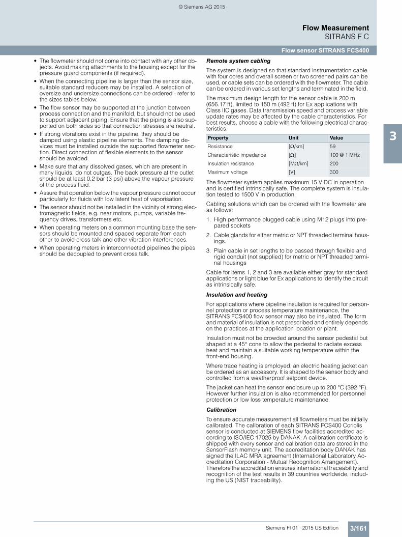
Remote system cablingThe system is designed so that standard instrumentation cable with four cores and overall screen or two screened pairs can be used, or cable sets can be ordered with the flowmeter. The cable can be ordered in various set lengths and terminated in the field.
The maximum design length for the sensor cable is 200 m (656.17 ft), limited to 150 m (492 ft) for Ex applications with Class IIC gases. Data transmission speed and process variable update rates may be affected by the cable characteristics. For best results, choose a cable with the following electrical charac-teristics:
The flowmeter system applies maximum 15 V DC in operation and is certified intrinsically safe. The complete system is insula-tion tested to 1500 V in production.
Cabling solutions which can be ordered with the flowmeter are as follows:
1. High performance plugged cable using M12 plugs into pre-pared sockets
2. Cable glands for either metric or NPT threaded terminal hous-ings.
3. Plain cable in set lengths to be passed through flexible and rigid conduit (not supplied) for metric or NPT threaded termi-nal housings
Cable for items 1, 2 and 3 are available either gray for standard applications or light blue for Ex applications to identify the circuit as intrinsically safe.
Insulation and heating For applications where pipeline insulation is required for person-nel protection or process temperature maintenance, the SITRANS FCS400 flow sensor may also be insulated. The form and material of insulation is not prescribed and entirely depends on the practices at the application location or plant.
Insulation must not be crowded around the sensor pedestal but shaped at a 45° cone to allow the pedestal to radiate excess heat and maintain a suitable working temperature within the front-end housing.
Where trace heating is employed, an electric heating jacket can be ordered as an accessory. It is shaped to the sensor body and controlled from a weatherproof setpoint device.
The jacket can heat the sensor enclosure up to 200 °C (392 °F). However further insulation is also recommended for personnel protection or low loss temperature maintenance.
CalibrationTo ensure accurate measurement all flowmeters must be initially calibrated. The calibration of each SITRANS FCS400 Coriolis sensor is conducted at SIEMENS flow facilities accredited ac-cording to ISO/IEC 17025 by DANAK. A calibration certificate is shipped with every sensor and calibration data are stored in the SensorFlash memory unit. The accreditation body DANAK has signed the ILAC MRA agreement (International Laboratory Ac-creditation Corporation - Mutual Recognition Arrangement). Therefore the accreditation ensures international traceability and recognition of the test results in 39 countries worldwide, includ-ing the US (NIST traceability).
Property Unit ValueResistance [/km] 59
Characteristic impedance [] 100 @ 1 MHz
Insulation resistance [M/km] 200
Maximum voltage [V] 300
FI01_2015_us_Kap03.book Seite 161 Freitag, 20. Februar 2015 10:20 10
Pressure/temperature curvesWith two major exceptions, the pressure rating of the flow sen-sors is independent of the process medium temperature. Design rules for flange connections in both the EN1092-1 and ASME B16.5 standards dictate pressure derating with increasing tem-perature. The charts below show the effect of process medium temperature on the pressure ratings for the flanges within the FCS400 product program.
EN1092-1 flanged sensors
ASME B16.5 flanged sensors
Flow sensor FCS400Parameter Unit ValueProcess pressure range [barg (psi)] 316L: 0 ... 100 (0 ... 1450)
Hastelloy C22: 0 ... 160 (0 ... 2321)
Process temperature range [°C (°F)] -50 ... +200 (-58 ... +392)
Ambient temperature range [°C (°F)] -40 ... +60 (-40 ... +140)
Transport temperature range [°C (°F)] -40 ... +70 (-40 ... +158)
Density range [kg/m3 (lb/ft3)] 1 ... 5000 (0.062 ... 312.2)
Process media Fluid group 1 (suitable for dangerous fluids)
Form Light slurry, liquid and non-condensing gas
No. of process values
• Primary process values • Mass flow
• Density
• Process medium temperature
• Derieved process values • Volume flow
• Corrected volume flow (with reference density)
• Fraction A:B
• Fraction % A:B
Performance specifications SensorParameter Unit DN 15 DN 25 DN 50 DN 80Max. zero point error [kg/h (lb/min)] 0.2 (0.007) 2.0 (0.072) 7.5 (0.276) 18 (0.66)
Sensor variantsSITRANS FCS400 sensors are available in three main variants: Standard, hygienic and NAMUR. A wide range of process con-nections is available for the FCS400 sensors. The available com-binations of type, sensor size and connection size are shown in the tables below.
Standard sensors
• Combinations shown ● are Mainstream products with delivery time of up to 15 days depending on the combination and pro-duction stock levels.
• Combinations shown O are Sidestream products with delivery from 45 to 90 days. Not all components are held in production stock for Sidestream products.
Sens
or
Con
nect
ion
EN 1
092-
1 B
1, P
N 1
6
EN 1
092-
1 B
1, P
N 4
0
EN 1
092-
1 B
1, P
N 6
3
EN 1
092-
1 B
1, P
N 1
00
EN 1
092-
1 D
Nut
, PN
40
EN 1
092-
1 D
Nut
, PN
63
EN 1
092-
1 D
Nut
, PN
100
AN
SI B
16.5
-200
9, c
lass
150
AN
SI B
16.5
-200
9, c
lass
300
AN
SI B
16.5
-200
9, c
lass
600
ISO
228
-1 G
pip
e th
read
ASM
E B
1.20
.1 N
PT p
ipe
thre
ad
DIN
118
51 H
ygie
nic
scre
wed
DIN
326
76 H
ygie
nic
Tri-c
lam
p
DIN
118
64-1
A A
sept
ic s
ecre
wed
DIN
118
64-2
A A
sept
ic fl
ange
d
ISO
285
2 H
ygie
nic
clam
ped
ISO
285
3 H
ygie
nic
scre
wed
SMS
1145
Hyg
inei
c sc
rew
ed
12-V
CO
-4 Q
uick
con
nect
JIS
B22
00:2
004/
10K
JIS
B22
00:2
004/
20K
JIS
B22
00:2
004/
40K
316 Stainless - Standard: 7ME461.-...DN 15 (½") DN 6 (¼") O O
DN 10 (3/8") O
DN 15 (½") O ● O ● O O O ● O ● ● ● ● ● ● ● O O O O
DN 20 (¾") ● O ● ●
DN 25 (1") O ● ● O ● ● O
DN 25 (1") DN 15 (½")
DN 25 (1") O ● O ● O O O ● O ● ● ● ● ● ● ● ● ● O O O O
DN 32 (1¼") O
DN 40 (1½") O ● O O O O ● O O
DN 50 (2") DN 25 (1")
DN 40 (1½") O ● O ● O O O O O ● O O O
DN 50 (2") O ● O ● O O O ● O ● ● ● ● ● ● ● ● ● O O O O
DN 65 (2½")
DN 80 (3") DN 50 (2")
DN 65 (2½") O ● O O ● O ● ●
DN 80 (3") O ● O ● O O O ● O ● ● ● ● ● ● ● O O O O
DN 100 (4") O O O O
FI01_2015_us_Kap03.book Seite 163 Freitag, 20. Februar 2015 10:20 10
The hygienic sensors all have maximum internal surface rough-ness < 0.8 µm and are EHEDG and 3A approved. Hygienic sen-sors are offered with process connection conforming to various international quick-connect clamps or threaded connectors. Pressure ratings are according to the relevant standard and the sensor size. Maximum pressure in the hygienic program is PN 40.
• Combinations shown ● are Mainstream products with delivery time of up to 15 days depending on the combination and pro-duction stock levels.
• Combinations shown O are Sidestream products with delivery from 45 to 90 days. Not all components are held in production stock for Sidestream products.
Aseptic flanged process connectionsThe aseptic flanges offered for FCS400 conform with the stan-dard DIN 11864-2A BF-A. The flange fitted to the sensor is there-fore the back flange and the seal is an O-ring.
The flange dimensions in the FCS400 program are as follows:
DIN 11864-2A BF-A flange dimensions
Sens
or
Con
nect
ion
DIN
118
51 0
.8 μ
m s
crew
ed
DIN
326
76 0
.8 μ
m T
ri-cl
amp
DIN
118
64-1
0.8
μm
scr
ewed
DIN
118
64-2
0.8
μm
flan
ged
ISO
285
2 0.
8 μm
cla
mpe
d
ISO
285
3 0.
8 μm
scr
ewed
316 SS - Hygienic: 7ME462.-...DN 15 (½") DN 6 (¼")
DN 10 (3/8") O
DN 15 (½") ● ● ● ●
DN 20 (¾") ●
DN 25 (1") O ● ●
DN 25 (1") DN 15 (½")
DN 25 (1") ● ● ● ● ● ●
DN 32 (1¼") O
DN 40 (1½") ● O O
DN 50 (2") DN 25 (1")
DN 40 (1½") O O ● O O
DN 50 (2") ● ● ● ● ● ●
DN 65 (2½")
DN 80 (3") DN 50 (2")
DN 65 (2½") ●
DN 80 (3") ● ● ● ● ● ●
DN 100 (4")
Size DN Pipe Bored1
Ring ODd11
Bolt Circled5
Bolt holes
Flange diameterd10
10 13 x 1.5 10 22.4 37 4 x 9 54
15 19 x 1.5 16 28.4 42 4 x 9 59
20 23 x 1.5 20 32.4 47 4 x 9 64
25 29 x 1.5 26 38.4 53 4 x 9 70
32 35 x 1.5 32 47.7 59 4 x 9 76
40 41 x 1.5 38 53.7 65 4 x 9 82
50 53 x 1.5 50 65.7 77 4 x 9 94
65 70 x 2.0 66 81.7 95 8 x 9 107
80 85 x 2.0 81 97.7 112 8 x 11 113
FI01_2015_us_Kap03.book Seite 164 Freitag, 20. Februar 2015 10:20 10
The NAMUR variants have build-in lengths according to NAMUR recommendation NE 132. The recommendations of NE 132 are stated for sensors with flanges the same size as the sensor nom-inal size, and for flanges to EN1092-1 PN 40 with B1 flange fac-ing. For couplings of other standards such as ASME B16.5 Class 150, the overall length incorporates the difference in length between standard EN and ASME flanges. NAMUR vari-ants are offered with flange and pipe thread connections ac-cording to EN, ISO oand ASME standards, as shown in the table below.
• Combinations shown ● are Mainstream products with delivery time of up to 15 days depending on the combination and pro-duction stock levels.
• Combinations shown O are Sidestream products with delivery from 45 to 90 days. Not all components are held in production stock for Sidestream products.
Sens
or
Con
nect
ion
EN 1
092-
1 B
1, P
N 1
6
EN 1
092-
1 B
1, P
N 4
0
EN 1
092-
1 B
1, P
N 6
3
EN 1
092-
1 B
1, P
N 1
00
EN 1
092-
1 D
Nut
, PN
40
EN 1
092-
1 D
Nut
, PN
63
EN 1
092-
1 D
Nut
, PN
100
AN
SI B
16.5
-200
9, c
lass
150
AN
SI B
16.5
-200
9, c
lass
300
AN
SI B
16.5
-200
9, c
lass
600
ISO
228
-1 G
pip
e th
read
ASM
E B
1.20
.1 N
PT p
ipe
thre
ad
DIN
118
51 H
ygie
nic
scre
wed
DIN
326
76 H
ygie
nic
Tri-c
lam
p
DIN
118
64-1
A A
sept
ic s
ecre
wed
DIN
118
64-2
A A
sept
ic fl
ange
d
ISO
285
2 H
ygie
nic
clam
ped
ISO
285
3 H
ygie
nic
scre
wed
316 Stainless - NAMUR: 7ME471.-...DN 15 (½") DN 6 (¼") O O
DN 10 (3/8") O
DN 15 (½") O ● O ● O O O ● O ● ● ● ● ● ● ●
DN 20 (¾") ● O ● ●
DN 25 (1") O ● ● O ● ●
DN 25 (1") DN 15 (½")
DN 25 (1") O ● O ● O O O ● O ● ● ● ● ● ● ● ● ●
DN 32 (1¼") O
DN 40 (1½") O ● O O O O ● O O
DN 50 (2") DN 25 (1")
DN 40 (1½") O ● O ● O O O O O ● O O
DN 50 (2") O ● O ● O O O ● O ● ● ● ● ● ● ● ● ●
DN 65 (2½") O
DN 80 (3") DN 50 (2")
DN 65 (2½") O ● O O ● O ● ●
DN 80 (3") O ● O ● O O O ● O ● ● ● ● ● ● ●
DN 100 (4") O O O O
FI01_2015_us_Kap03.book Seite 165 Freitag, 20. Februar 2015 10:20 10
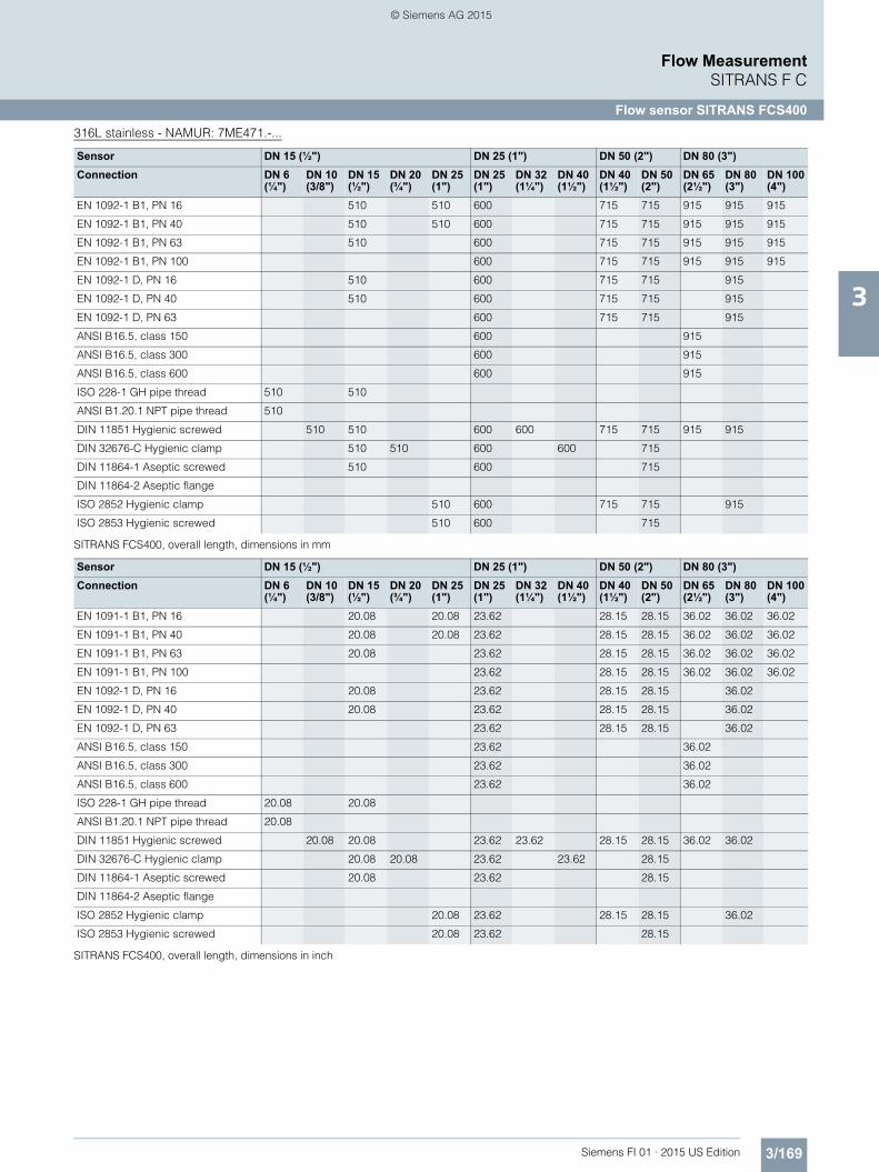
Overall lengthThe overall length (build-in length) of each sensor depends on the connection standard and the pressure rating. The tables below summarize the dimensions available at the time of publishing. Please contact Siemens for further information about our desired pro-cess connection specification.
316L stainless - Standard: 7ME461.-...
SITRANS FCS400, overall length, dimensions in mm
SITRANS FCS400, overall length, dimensions in inch
FCT030 is based on the latest developments within digital signal processing technology – engineered for high measuring perfor-mance, fast response to step changes in flow, fast dosing appli-cations, high immunity against process noise, easy to install commission and maintain.
The FCT030 transmitter delivers true multi-parameter measure-ments i.e. massflow, volumeflow, corrected volumeflow, density, temperature and fraction.
The FCT030 IP67 transmitter can be remote connected or com-pact mounted with all sensors of type FCS400, sizes DN 15 to DN 80.
FractionThe transmitter FCT030 can be set up at works to measure and report various fraction concentrations of two-part mixtures or so-lutions. Where a discrete relationship exists between concentra-tion and density at particular temperatures a calculation is per-formed and the percentage concentration by volume or mass of Part A or Part B (100 % minus Part A) is measured. For solutions and some mixtures the total mass, or dry weight, is also avail-able.
In some industries, a selection of standard density scales has been adopted to represent the density or relative density of the process fluid.
If "Standard fractions" option is chosen at ordering, the following fraction or standard density scales can be selected in the setup menu:
■ Application
SITRANS FC430 mass flowmeters are suitable for applications within the entire process industry where there is a demand for accurate flow measurement. The meter is capable of measuring both liquid and gas flow.
Coriolis flowmeters can be applied in all industries, such as:• Chemical & Pharma: detergents, bulk chemicals, acids, alka-
• Food & Beverage: dairy products, beer, wine, soft drinks, °Brix/°Plato, fruit juices and pulps, bottling, CO2 dosing, CIP/SIP-liquids, mixture recipe control
• Automotive: fuel injection nozzle & pump testing, filling of AC units, engine consumption
• Oil & Gas: filling of gas bottles, furnace control, test separators • Hydrocarbon processing: oil refining, derivatives manufactur-
ing, polymerisation • Water & Waste Water: dosing of chemicals for water treatment
The multiple outputs and bus communication mean that all of the process information can be read either instantaneously (10 ms update) or periodically as plant operation requires.
■ Benefits
Flow calculation and measurement• Dedicated mass flow calculation with DSP technology• Fast dosing and flow step response with maximum 10 ms re-
sponse time.• 100 Hz update rate to all outputs• Maximum data age from pickup to output is 20 ms (two update
cycles)• Independent low flow cut-off settings for mass and volume
flowrates• Automatic zero-point adjustment on command from discrete
input or host system• Empty pipe monitoring
Operation and display• User-configurable operation display
- Full graphical display 240 x 160 pixels with up to 6 program-mable views
- Self-explaining alarm handling/log in clear text- Help text for all parameters appears automatically in the con-
figuration menu- Keypad can be used for controlling dosing as start/stop/
hold/reset• SensorFlash technology stores production specific system
documentation and provides removable memory of all flow-meter setups and functions- Calibration certificates- Pressure and material test certificates (as ordered)- Non-volatile memory backup of operational data- Transfer of user configuration to other flowmeters
Alarms and safety• Advanced diagnosis and service menu enhances trouble-
shooting and meter validation• Configurable upper and lower alarm and warning limits for all
process values• Alarm handling can be selected between Siemens and
NAMUR standard configurations• Designed from the ground up and certified for integrated
safety in accordance with IEC 61508 and IEC 61511.- SIL 2 (single-channel operation)- SIL 3 (dual-channel operation)Unlike many systems which are certified in practice, the SITRANS FC430 system is certified in design, which is a higher qualification and more robust for secure implementa-tion of safety systems.
Outputs and control• Built-in dosing controller with compensation and monitoring
comprising 3 built-in totalizers• Multi-parameter outputs, individually configurable for mass-
flow, volumeflow, corrected volumeflow, density, temperature or fraction flow such as °Brix or °Plato
• API number• Balling• °Baumé light• °Baumé heavy • °Brix • °Oeschlé°• Plato• Specific Gravity
• °Twaddell• %HFCS42• %HFCS55• %HFCS90• Ethanol-Water 0 % to 20 %• Ethanol-Water 15 % to 35 %• Ethanol-Water 30 % to 55 %• Ethanol-Water 50 % to 100 %
FI01_2015_us_Kap03.book Seite 170 Freitag, 20. Februar 2015 10:20 10
Up to four I/O channels are configured as follows:
Channel 1Channel 1 is 4 to 20 mA analog output with HART 7.2 which can be validated and setup for safety critical applications (SIL 2). The current signal can be configured for massflow, volumeflow or density.
Channel 2Channel 2 is a signal output which can be freely configured for any process variable.• Analog current (0/4 to 20 mA)• 3 stage analog valve dosing control• Frequency or pulse• Discrete one or two-valve dosing control in combination with
channel 3 or 4• Operational and alarm status
Channels 3 and 4Channels 3 and 4 can be ordered with signal (freely configured for any process variable) or relay outputs, or signal input.
SignalSignal output can be user configured to:• Analog current (0/4 to 20 mA)• 3 stage analog valve dosing control• Frequency or pulse• Redundant frequency or pulse (linked to Channel 2)• Discrete one or two-valve dosing control• Operational and alarm status
RelayRelay output(s) can be user configured to:• Discrete one or two-valve dosing control• Operation status including flow direction• Alarm status
Signal inputSignal input can be user-configured for• Dosing control• Totalizer reset functions• Force or freeze output(s)• Inititate automatic zero point adjustment
Signal outputs and inputs are individually ordered as active or passive.
During service and maintenance all outputs can be forced to a preset value for simulation, verification or calibration purposes.
Approvals and certificatesThe FC430 Coriolis flowmeter program was designed from the ground up to comply with or exceed the requirements of interna-tional standards and regulations.
■ Design
The transmitter SITRANS FCT030 is designed in an IP67/NEMA 4X aluminum enclosure with corrosion resistant coating. It can be remote connected or compact mounted with an FCS400 sensor of size DN 15, DN 25, DN 50 or DN 80.
FCT030 is available as standard with one current, HART 7.2 out-put and can be ordered with additional input/output functions.
The transmitter has a modular design with discrete, replaceable electronic modules and connection boards to maintain separa-tion between functions and facilitate field service. All modules are fully traceable and their provenance is included in the trans-mitter setup.
SensorFlash SensorFlash is a standard, 1 GByte micro SD card with the ability to be updated by PC. It is supplied with each sensor with the complete set of certification documents including calibration re-port. Material, pressure test, factory conformance certificates are optional at ordering.
The Siemens SensorFlash memory unit offers the following fea-tures and benefits: • Automatically program any similar transmitter in seconds to
the operation standard• Transmitter replacement in less than 5 minutes• True "plug & play" provided by integrated cross-checking data
consistency and HW/SW version verification• Permanent database of operational and functional information
from the moment that the flowmeter is switched on• New firmware updates can be downloaded from the SIEMENS
internet portal for Product Support and placed onto Sensor-Flash (unmounted from the transmitter and inserted into a PC’s SD card slot). The firmware is then inserted into the existing flowmeter and the complete system upgraded.
■ Function
The following functions are available:• Mass flowrate, volume flowrate, density, process temperature,
fraction flow• Up to four output/input channels selected at ordering• Outputs can be individually configured with mass, volume,
density etc.• Three built-in totalizers which can count positive, negative or
net flows• Low flow cut-off, adjustable• Density cut-off or empty pipe cut-off, adjustable• Flow direction adjustable• Alarm system consisting of alarm-log, alarm pending menu• Internal data logger is updated each 10 minutes with opera-
tional data such as system health, totalizer values, all configu-rations and data needed for Custody Transfer requirements to OIML R 117
• Display of operating time with real-time clock. Daylight saving time is not implemented
• Uni/bidirectional flow measurement• Flowrate outputs are freely configurable between maximum
negative and maximum positive flows according to the sensor capacity
• Limit switches programmable for flow, density, temperature or fraction process values. Limit points can be graded as warn-ing and alarm for values both above and below nominal pro-cess conditions
• Process noise filter for optimization of measurement perfor-mance under non-ideal application conditions. 5-stage pump-ing filter compensates for flow fluctuations caused by e.g. sin-gle acting piston pumps
• Full dosing controller with 5 user-configurable recipes• Automatic zero adjustment menu, with zero point evaluation
display• Full service menu for effective and straight forward application
and meter troubleshooting • Precise temperature measurement ensures optimum accu-
racy on massflow, density and fraction flow.• Fraction flow computation is based on a 5th-order algorithm
matching known applications. All standard fraction calcula-tions fit within 0.1% of the true value.
FI01_2015_us_Kap03.book Seite 171 Freitag, 20. Februar 2015 10:20 10
NAMUR Within the value limits according to "General requirements" with error criteria A in accordance with NE 21
EnvironmentEnvironmental conditions acc. to IEC/EN/UL 61010-1
• Altitude up to 2000 m• Pollution degree 2
Maintenance The flowmeter has a built-in error log/pending menu which should be inspected on a regular basis.
Cable glands Cable gland are available in Nylon, Nickel plated brass or stainless steel (316L/W1.4404) in the following dimensions:• M20• ½" NPT
Cable Standard industrial signal cable up to 200 m long with 2 x screened pairs or 4-wire overall screen can be laid between the sensor and transmitter. Siemens offers cables in a selection of pre-cut lengths and prepared for either gland or plug connection.
1) With 300 internal impedance. For coil switching use the passive output option.
FI01_2015_us_Kap03.book Seite 172 Freitag, 20. Februar 2015 10:20 10
CT plug Tamper cover for CT lock-ing. Fits over the M12 plug at both sensor and transmit-ter ends of the remote sys-tem cable
A5E31478498
Bag of glands (metric) in black plastic1)
A5E03907414
Bag of glands, (metric) in gray plastic Ex e/i1)
A5E03907424
Bag of glands (metric) in AISI 316 SS Ex e/i1)
A5E03907429
Bag of glands (metric) in NiPlatedBrass Ex e/i1)
A5E03907430
Bag of glands (NPT) in black plastic2)
A5E03907435
Bag of glands (NPT) in gray plastic Ex e/i2)
A5E03907451
Bag of glands (NPT) in AISI 316 SS Ex e/i2)
A5E03907467
Bag of glands (NPT) in NiPlatedBrass Ex e/i2)
A5E03907473
Standard cable (non-Ex) with M12 plugs, PO insula-tion and PUR sleeve, gray,-40 ... +80 °C (-40 ... +176 °F)
• 5 m (16.4 ft) A5E03914805• 10 m (32.8 ft) A5E03914850• 25 m (82 ft) A5E03914853• 50 m (164 ft) A5E03914859• 75 m (246 ft) A5E03914861• 150 m (492 ft) A5E03914874Standard cable (non-Ex) for termination, PO insulation and PUR sleeve, gray, -40 ... +80 °C (-40 ... +176 °F)
• 5 m (16.4 ft) A5E03914833• 10 m (32.8 ft) A5E03914849• 25 m (82 ft) A5E03914854• 50 m (164 ft) A5E03914856• 75 m (246 ft) A5E03914864• 150 m (492 ft) A5E03914873
Standard cable (Ex) with M12 plugs, PO insulation and PUR sleeve, blue,-40 ... +80 °C (-40 ... +176 °F)
• 5 m A5E03914929• 10 m A5E03914962• 25 m A5E03914995• 50 m A5E03915004• 75 m A5E03915074• 150 m A5E03915088Standard cable (Ex) for ter-mination, PO insulation and PUR sleeve, blue, -40 ... +80 °C (-40 ... +176 °F)
• 5 m A5E03914945• 10 m A5E03914973• 25 m A5E03914984• 50 m A5E03915015• 75 m A5E03915057• 150 m A5E03915100Suitcase for comprehen-sive sales and training for FC430It comes in a special suit-case with a fan imple-mented that allows the flowmeter to demonstrate airflow.
A5E31467598
Suitcase for comprehen-sive sales support and training for FC410. It comes in a special suit-case with an S7-1200 PLC and HMI touch-screen dis-play. The operating code is open-source and can be copied to customers to assist with system integra-tion.
A5E33219071
Service toolkit for field main-tenance of transmitter and sensor components. Con-tains all hand tools neces-sary for maintenance. Other tools may be required for installation.
A5E03722877
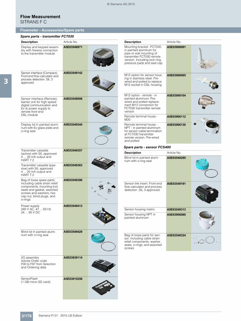
Description Article No.
FI01_2015_us_Kap03.book Seite 174 Freitag, 20. Februar 2015 10:20 10
Display and keypad assem-bly with firewire connection to the transmitter module
A5E03548971
Sensor interface (Compact). Front end flow calculator and process detection. SIL 3 approved
A5E03549142
Sensor interface (Remote); barrier unit for high speed digital communication and Ex ib power supply to remote front end DSL module
A5E03549098
Display lid in painted alumi-num with Ex glass plate and o-ring seal
A5E03549344
Transmitter cassette (active) with SIL approved 4 ... 20 mA output and HART 7.2
A5E03549357
Transmitter cassette (pas-sive) with SIL approved 4 ... 20 mA output and HART 7.2
A5E03549383
Bag of loose spare parts; including cable strain relief components, mounting tool, seals and gasket, assorted screws and washers, hex cap nut, blind plugs, and o-rings
A5E03549396
Power supply240 V AC, 47 ... 63 Hz24 ... 90 V DC
A5E03549413
Blind lid in painted alumi-num with o-ring seal
A5E03549429
I/O assemblyAdvise Order code F00 to F97 from Selection and Ordering data
A5E03939114
SensorFlash (1 GB micro SD card)
A5E03915258
Mounting bracket - FCT030; in painted aluminum for pipe or wall mounting of transmitter FCT030 remote version. Including lock ring, pressure pads and seal cap
A5E03906091
M12 option for sensor hous-ing in stainless steel. Pre-wired and potted to replace M12 socket in DSL housing
A5E03906095
M12 option - remote - in painted aluminum. Pre-wired and potted replace-ment M12 connection for FCT030 transmitter remote version
A5E03906104
Remote terminal house - M20
A5E03906112
Remote terminal house - NPT - in painted aluminum for sensor cable termination at FCT030 transmitter remote version. Pre-wired and potted
A5E03906130
Description Article No.
Blind lid in painted alumi-num with o-ring seal
A5E03549295
Sensor link insert. Front end flow calculator and process detection. SIL 3 approved
A5E03549191
Sensor housing metric A5E03549313Sensor housing NPT in painted aluminum
A5E03906080
Bag of loose parts for sen-sor; including cable strain relief components, washer, seals, o-rings, and assorted screws
A5E03549324
Description Article No.
FI01_2015_us_Kap03.book Seite 176 Freitag, 20. Februar 2015 10:20 10
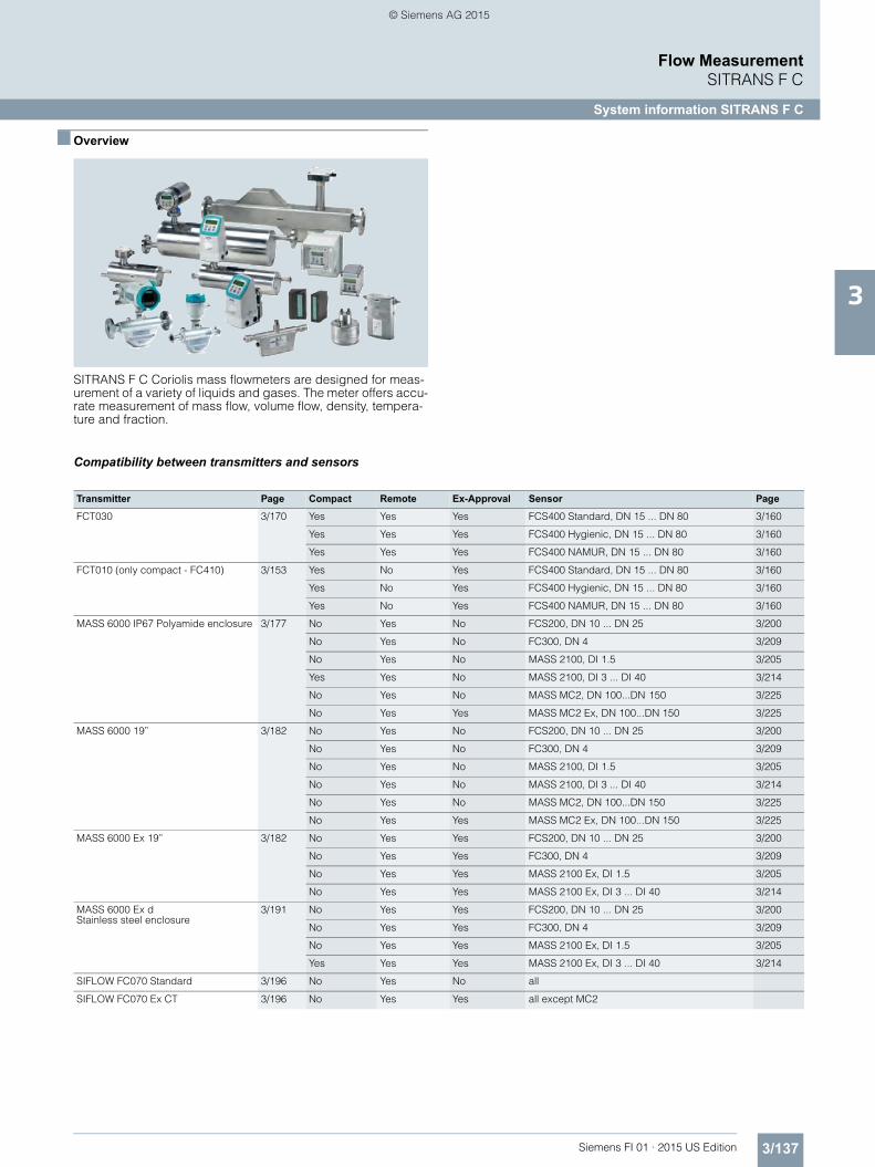
SITRANS F C Coriolis mass flowmeters are designed for meas-urement of a variety of liquids and gases. The meter offers accu-rate measurement of mass flow, volume flow, density, tempera-ture and fraction.
Greater flexibility• Wide product program• High performance and top-end flowmeters• Compact or remote installation using the same transmitters
and sensors within their flowmeter series
Easier commissioning
All SITRANS F C Coriolis flowmeters feature a sensor related memory unit SENSORPROM or SensorFlash which stores cali-bration data and transmitter settings for the lifetime of the prod-uct.
At commissioning the flowmeter commences measurement without any initial programming.
Easier service• Comprehensive self-diagnosis and service menu enhances
troubleshooting and meter verification.• Transmitter replacement requires no programming.
SENSORPROM automatically updates all settings after initial-ization.
Room for growth• FC430:
Digital platform allows for any sensor in the range to be matched in compact or remote. The wide range of sensors are all certified to SIL2 or SIL3 (redundant) with the FCT030 trans-mitter in compact mode.
• MASS 6000:USM II the Universal Signal Module with "plug & play" simplic-ity makes it easy to access and integrate the flowmeter with al-most any system and bus-protocol and it ensures the flowme-ter will be easy to upgrade to future communication/bus platforms.
• SIFLOW: Direct integration into SIMATIC S7-300 systems as a flowmeter specific I/O module ensures fast and smooth startup, seam-less integration, fast operation.
■ Application
Coriolis flowmeters are generally suitable for measuring liquids and gases. The flow measurement is independent of changes in process conditions/parameters such as temperature, density, pressure, viscosity, conductivity and flow profile.
Due to this versatility the meter is easy to install and use. The Co-riolis flowmeter is recognized for its high accuracy over a wide turn-down ratio.
The main applications of the Coriolis flowmeter can be found in all industries, such as:Chemical and pharma Detergents, bulk chemicals, phar-
maceuticals, acids, alkalis, filling and dosing
Food and beverage Dairy products, beer, wine, soft-drinks, °Plato/°Brix, fruit juices and pulps, bottling, CO2 dosing, CIP-liquids
Automotive Fuel injection nozzle and pump testing, filling of AC units, engine consumption measurement, paint robots
Oil and gas Filling of gas bottles, furnace con-trol, CNG-dispensers, test separa-tors, LPG, well-head water-cut monitoring
Water and waste water Dosing of chemicals for water treatment
FI01_2015_us_Kap03.book Seite 138 Freitag, 20. Februar 2015 10:20 10
● = available1) Not available for DN 150 sensor.2) See technical specifications.3) DI 3 and DI 64) DI 15, DI 25 and DI 40 are not available for Hastelloy C22/2.4602.
5) Only when mounted in enclosure.6) Process connectors in AISI 316Ti/1.45717) Sensor pressure limited to 100 bar (AISI 316L) and 160 bar (Hastelloy C22)8) Sensor pressure limited to 100 bar (AISI 316L) and 150 bar (Hastelloy C22)
Please see Product selec-torwww.pia-selector.automa-tion.siemens.com on the Internet, since some con-strains might be related to some of the features
Compressed gas-eous fuel measur-ing systems for vehicles - OIML R 139
● ●10)
Other media than water pattern approval - OIML R 117
●
Harzardous locations
ATEX ● ● ● ● ● ●9)
● ● ● ●3)4)
IECEx ● ● ● ●4)
FM ● ● ● ●9)
UL ●1)
●1) ● ●
2)
CSA ● ● ●4)
NEPSI ● ● ●
INMETRO ● ●
Ordinary locations
USL, CNL-Flow-meter
c-UL-us ●2)
●7)
USR, CNR-Flow-meter
c-UL-us ●2)
●5)6)
PED
Fluid group 1Category II, Module H
PED Directive 97/23/EC
● ● ●8)
Module B1 + D 0/25 ... 100 bar, -80/200ºC, DN 20 ...150
PED Directive 97/23/EC
●
CRN
Category F OF10769.5C
CRN ● ● ● ●11)
●
Pharma
EHEDG TUM ● ●
3A ● ●
Note: Special conditions for safe use might be specified in certificates or operating instructions.
● = available1) Sensor pressure max. 100 bar (1450 psi)2) Only remote version3) Can be placed in zone 2 if mounted in minimum IP54 cabinet.4) Only Ex version5) 24 V; IP206) 115 ... 230 V; IP207) 115 ... 230 V; IP658) Only DI 25 and DI 409) For sizes DN 100 only10) Install in Div. 2, sensor interface into Div. 1, only Ex CT version11) Only DI 6 is CRN
Please see Product selec-torwww.pia-selector.automa-tion.siemens.com on the Internet, since some con-strains might be related to some of the features
The flow measuring principle is based on the Coriolis effect. The flowmeter consists of a system FC410 or FC430 or a combina-tion of a sensor type MASS 2100/FC300/FCS200/MC2 and a transmitter type MASS 6000/SIFLOW FC070.
The SITRANS F C sensors are energized by an electro-mechani-cal driver circuit which oscillates the pipe at its resonant fre-quency.
Two pick-ups, 1 and 2 are placed symmetrically on both sides of the driver. When liquid or gas flows through the sensor, Coriolis force will act on the measuring pipe and cause a pipe deflection which can be measured as a phase shift on pick-up 1 and 2. The phase shift is proportional to the mass flow rate.
The amplitude of the driver is automatically regulated to ensure a stable output from the 2 pick-ups.
The temperature of the sensor is measured by a Pt1000. For MC2 the temperature is measured with a Pt100.
The flow-proportional signal from the 2 pick-ups, the tempera-ture measurement and the driver frequency are fed into the SITRANS F C transmitter for calculations of mass, volume, frac-tion, temperature and density.
The signal transfer function is based on a DFT technology (Dis-crete Fourier Transformation).
The transmitter has a built-in noise filter, which can be used to improve the meter’s performance if the installation and applica-tion conditions are not ideal. Typically influence from process noise such as pump pulsations, mechanical vibrations, oscillat-ing valves can be reduced considerably.
For communication purposes the SITRANS F C MASS 6000 transmitters have a CAN interface with a Siemens specific pro-tocol. This concept is known as the USM II (Universal Signal Module) concept. The idea is that extra output modules or com-munication modules can be connected to this bus, making it possible to configure the flowmeter for the precise task in hand. When the internal CAN bus detects the installed module, it is au-tomatically programmed to factory settings via the SENSORPROM memory unit, and the new menu is visible in the MASS 6000 display.
SENSORPROM and SensorFlash flow memory units
FC410 flow transmitters communicate via Modbus RTU and FC430 via HART. Currently the USM platform handles all present and future communication protocols, e.g., PROFIBUS DP, PROFIBUS PA, HART, Modbus, FOUNDATION Fieldbus H1 and DeviceNet.
■ Integration
Installation of MASS 2100/FC300 and MC2 sensors
Installation requirements/System design information
The SITRANS F C mass flowmeter is suitable for in- and outdoor installations. The standard instrument meets the requirements of Protection Class IP67/NEMA 6 or IP65. The flowmeter is bidirec-tional and can be installed in any orientation, however, the sen-sor is not self-emptying in all positions. It is important to ensure that the meter tubes are always com-pletely filled with homogeneous fluid. Otherwise measuring er-rors may occur.
The corrosion resistance of the fluid-wetted materials must be evaluated.The pressure drop through the sensor is a function of the prop-erties of the fluid and the flow rate. The Sizing Program (down-load from https://pia.khe.siemens.com/index.aspx?nr=11501) can be used to calculate the pressure drop.
The preferred flow direction is indicated by the arrow on the flow-meter. Flow in this direction will be indicated as positive.
Installation orientation • FCS400 – sensors
The optimal installation orientation is vertical with flow up-wards (liquids) and up to 10° off vertical for self-draining.
• MASS 2100/FC300 – sensorsThe optimal installation orientation is horizontal.
• MC2 – sensorsThe optimal installation orientation is vertical with the flow up-wards.
Supports • In order to support the weight of the flowmeter and to ensure
reliable measurements when external effects exist (e.g. vibra-tions), the sensor should be installed in well-supported pipe-lines. Supports or hangers should be installed symmetrically and stress-free in close proximity to the process connections. FCS400 sensors can be supported at the junction between the process connection and the main body of the sensor.
Shut-off devices • To conduct a system zero adjustment, shut-off devices are re-
quired in the pipeline.- In horizontal installations at the outlet for FC300 and MC2
and the inlet for MASS 2100.- In vertical installations at the inlet.
• When possible, shut-off devices should be installed both up- and downstream of the flowmeter. A bypass valve is recom-mended where regular zero adjustment is planned to avoid disruption of the flowing system.
Installation: straight run requirements• The mass flowmeter does not require any flow condition or
straight inlet sections. Care should be exercised to ensure that any valves, gates, sight glasses etc. do not cavitate and are not set into vibration by the flowmeter.
System design information • The presence of gas bubbles in the fluid may result in erro-
neous measurements, particularly in the density measure-ment. Therefore the flowmeter should not be installed at the highest point in the system where bubbles are possibly larg-est.
• Long drop lines downstream from the flowmeter should be avoided to prevent the meter tube from draining during oper-ation.
• The flowmeter should not come into contact with any other ob-jects. Avoid attachments to the housing.
• When the cross-section of the connecting pipeline is larger than the sensor size, suitable standard reducers may be in-stalled.
• If strong vibrations exist in the pipeline, they should be damped using elastic pipeline elements. The damping de-vices must be installed outside the supported flowmeter sec-tion and outside the section between the shut-off devices.
• Make sure that any dissolved gases, which are present in many liquids, do not outgas. The back pressure at the outlet should be at least 0.2 bar (3 psi).
• Assure that operation below the vapor pressure cannot occur when a vacuum exists in the meter tube or for fluids which boil readily.
• The sensor should not be installed in the vicinity of strong elec-tromagnetic fields, e.g. near motors, pumps, transformers etc.
FI01_2015_us_Kap03.book Seite 142 Freitag, 20. Februar 2015 10:20 10
• When operating more than one meter in one or multiple inter-connected pipelines, the sensors should be spaced distant from each other or the pipelines should be decoupled to pre-vent cross talk.
Zero adjustment • In order to adjust the zero under operating conditions it must
be possible to reduce the flow rate to „ZERO“ while the meter tube is completely filled. It is important for accurate measure-ments that during the zero adjustment there are no gas bub-bles in the flowmeter. It is also important that the pressure and temperature in the meter tube be the same as that which exists during operation.
■ Technical specificationsFlowmeter uncertainty/specificationsTo ensure continuous accurate measurement, flowmeters must be calibrated. The calibration is conducted at Siemens flow fa-cilities accredited according to ISO/IEC 17025 by DANAK. The accreditation body DANAK has signed the ILAC MRA agreement (International Laboratory Accreditation Corporation - Mutual Recognition Arrangement). Therefore the accreditation ensures international traceability and recognition of the test re-sults in 39 countries worldwide, including the US (NIST traceabil-ity).A calibration certificate is shipped with every sensor and cali-bration data are stored in the SENSORPROM memory unit. FC410 and FC430 meters have the calibration data written to the front end section. A backup of all calibrations and PDF copies of all certificates are stored in the SensorFlash.FCS400 sensors and FCT030/FCT010 transmitters
MASS 2100 sensors and MASS 6000 transmitters
MC2 sensors and MASS 6000 transmitters
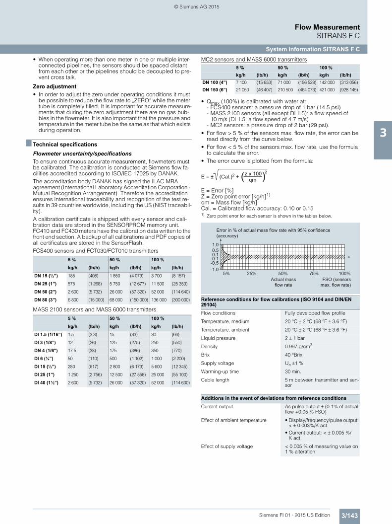
• Qmax (100%) is calibrated with water at:- FCS400 sensors: a pressure drop of 1 bar (14.5 psi)- MASS 2100 sensors (all except Di 1.5): a flow speed of
10 m/s (Di 1.5: a flow speed of 4.7 m/s)- MC2 sensors: a pressure drop of 2 bar (29 psi).
• For flow > 5 % of the sensors max. flow rate, the error can be read directly from the curve below.
• For flow < 5 % of the sensors max. flow rate, use the formula to calculate the error.
• The error curve is plotted from the formula:
E = Error [%]Z = Zero point error [kg/h]1)
qm = Mass flow [kg/h]Cal. = Calibrated flow accuracy: 0.10 or 0.151) Zero point error for each sensor is shown in the tables below.
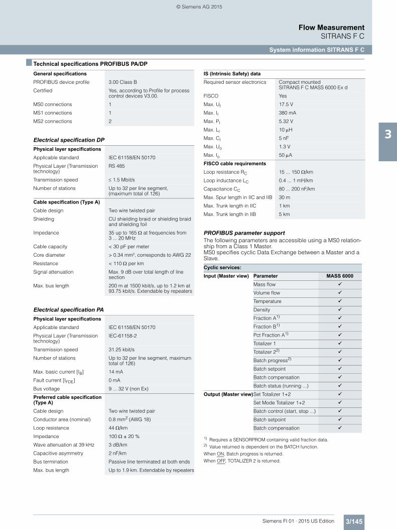
PROFIBUS parameter supportThe following parameters are accessible using a MS0 relation-ship from a Class 1 Master.MS0 specifies cyclic Data Exchange between a Master and a Slave.
1) Requires a SENSORPROM containing valid fraction data.2) Value returned is dependent on the BATCH function.
When ON, Batch progress is returned.
When OFF, TOTALIZER 2 is returned.
General specificationsPROFIBUS device profile 3.00 Class B
Certified Yes, according to Profile for process control devices V3.00.
MS0 connections 1
MS1 connections 1
MS2 connections 2
Physical layer specificationsApplicable standard IEC 61158/EN 50170
Physical Layer (Transmission technology)
RS 485
Transmission speed 1.5 Mbit/s
Number of stations Up to 32 per line segment, (maximum total of 126)
Cable specification (Type A)Cable design Two wire twisted pair
Shielding CU shielding braid or shielding braid and shielding foil
Impedance 35 up to 165 at frequencies from 3 ... 20 MHz
Cable capacity < 30 pF per meter
Core diameter > 0.34 mm², corresponds to AWG 22
Resistance < 110 per km
Signal attenuation Max. 9 dB over total length of linesection
Max. bus length 200 m at 1500 kbit/s, up to 1.2 km at 93.75 kbit/s. Extendable by repeaters
Physical layer specificationsApplicable standard IEC 61158/EN 50170
Physical Layer (Transmission technology)
IEC-61158-2
Transmission speed 31.25 kbit/s
Number of stations Up to 32 per line segment, maximum total of 126)
Max. basic current [IB] 14 mA
Fault current [IFDE] 0 mA
Bus voltage 9 ... 32 V (non Ex)
Preferred cable specification (Type A)Cable design Two wire twisted pair
Conductor area (nominal) 0.8 mm2 (AWG 18)
Loop resistance 44 /km
Impedance 100 ± 20 %
Wave attenuation at 39 kHz 3 dB/km
Capacitive asymmetry 2 nF/km
Bus termination Passive line terminated at both ends
Max. bus length Up to 1.9 km. Extendable by repeaters
IS (Intrinsic Safety) dataRequired sensor electronics Compact mounted