SITRANS F M TRANSMAG 2 with the SITRANS F M 911/E sensor is a pulsed alternating field magnetic flowmeter where the mag-netic field strength is much higher than conventional DC pulsed magnetic flowmeters.
■ Benefits
• Wide range of sizes DN 15 to DN 1000 (½" to 40")• Broad range of liner and electrode materials for extreme pro-
cess medias• Fully welded construction provides a ruggedness that suits
the toughest applications and environments.• Automatic reading of SmartPLUG for easy commissioning• Simple menu operation with two-line display• Comprehensiv self-diagnostic with selfmonitoring and internal
simulation
■ Application
The main applications of the SITRANS F M transmitter TRANSMAG 2 can be found in the following sectors:• Pulp and Paper industry• Mining industry
The patented pulse alternating field technology is ideal for diffi-cult applications like:• High concentrated paper stock > 3 %• Heavy mining slurries• Mining slurries with magnetic particles.• Low conductive medias 1 S/cm (0.1 S/cm depending on
medium)
■ Design
• Available for remote mounting• PROFIBUS PA (profile 2.0) / HART communication• Analog output and digital outputs for pulses, device status,
limits, flow direction, frequency output
■ Mode of operation
The flow measuring principle is based on Faraday’s law of elec-tromagnetic induction according to which the sensor converts the flow into an electrical voltage proportional to the velocity of the flow.
■ Function
The TRANSMAG 2 is a microprocessor-based transmitter with a build-in alphanumeric display in several languages. The trans-mitters evaluate the signals from the associated electromagnetic sensors and also fulfil the task of a power supply unit which pro-vides the magnet coils with a constant current.
The magnetic flux density in the sensor is additionally monitored by reference coils.
Further information on connection, mode of operation and instal-lation can be found in the data sheets for the sensors.
Displays and keypad
Operation of the transmitter can be carried out using:• Keypad and display unit• HART communicator• PC/laptop and SIMATIC PDM software via HART communica-
tion• PC/laptop and SIMATIC PDM software using PROFIBUS PA
communication
HART communication
PROFIBUS PA communication
Operating and display panel
PC/ laptop
Coupling module
HART communicator RS 232
min. 230 Ω
Transmitter withPROFIBUS PA interface
Coupler withpower supply
Bus term.Master
PROFIBUS DP PROFIBUS PA
.......
T
+
FI01_2015_en_Kap03.book Seite 104 Dienstag, 14. Oktober 2014 9:17 09
Measuring principle Electromagnetic with pulsed alternating field (PAC)
Magnetic field excitation Automatic power supply syn-chronization
- 50 Hz AC power supply Bipolar (16.7 Hz)Bipolar with prepulse (10 Hz)Unipolar (8.33 Hz)
- 60 Hz AC power supply Bipolar (20 Hz)Bipolar with prepulse (12 Hz)Unipolar (10 Hz)
Accuracy under referenceconditions
Measuring tolerance of pulse output
• With v > 0.25 m/s (0.82 ft/s) 0.5 % of measured value 1.2 mm/s (0.05 inch/s)
• With v < 0.25 m/s (0.82 ft/s) 2.5 mm/s (0.1 inch/s)
Measuring tolerance of analog out-put
As pulse output plus 0.1 % conversion error 20 µA
Repeatability 0.2 % of measured value
Reference conditions
• Process temperature 25 °C 5 °C (77 °F 9 °F)
• Ambient temperature 25 °C 5 °C (77 °F 9 °F)
• Warm-up time Min. 30 min
• Installation conditions Inlet pipe section 10 x DNOutlet pipe section 5 x DNInstalled centered in pipe
• Medium Water without gaseous or solid components
CalibrationStandard production calibration, calibration report shipped with sen-sor
Zero-point, 2 x 25 % and 2 x 90 %
Output
Electrical isolation Outputs electrically isolated from one another and from the power supply, max. 60 V permissible against PE/equipotential bonding
Current output 0/4 ... 20 mA(7ME5034-0…. or 7ME5034-2….)
• Signal
- Upper limit 0/4 … 20 mA, selectable
- Failure 20 … 22.5 mA, optional 3.6; 20 or 24 mA
• Load
- Output max. 600 , max. load voltage 15 V DC
- For HART communication 250
Communication Via analog output with PC cou-pling module or HART communi-cator
• Protocol HART, version 5.1
Digital output
Signal
• Output Configurable as active or passive signals
- Active signal 24 V DC, 24 mA, Ri = 170
- Passive signal Open collector, max. 30 V DC, 200 mA
Output configuration
• Pulse
- Pulse significance 5000 pulses/s
- Pulse width 0.1 ms
• Limit frequency 10000 Hz
• Limits Limits for flow and quantity, flow direction, alarm
Digital output 2 (relay) (only 7ME5034-0.…)
Relay NC or NO function
• Rating Max. 5 W, max. 50 V AC/DC, max. 200 mA
• Output configuration Limits for flow and quantity, flow direction, alarm
Digital input (optional to digital output 2) (only 7ME5034-2.…)
• Input function configurable as high-active or low-active
Set measured value or counter to zero
• Signal voltage Max. 30 V DC, Ri = 3 k:High level: +11 ... +30 V DCLow level: -30 ... +5 V DC
For PROFIBUS devices
PROFIBUS PA (for PROFIBUS-devices 7ME5034-1….)
• Communication Layer 1 and 2 according to PROFIBUS PA Transmission according to IEC 1158-2 Layer 7 (protocol layer) according to PROFIBUS PA and DP V1 (EN 50170)Device class B, device profile 2.0 Max. 4 simultaneous C2 connec-tions
• Bus voltage 9 ... 32 V DC permissible
• Current consumption from bus 10 mA; limited to 15 mA in event of fault by electrical current limita-tion
Rated operating conditions
Installation conditions See also sensor
Ambient temperature
• Operation -20 ... +60 °C (-4 ... +140 °F)
• Display module 0 ... 50 °C (32 ... 122 °F)
Storage -25 ... +80 °C (-13 ... +176 °F)
Degree of protection IP67/NEMA 4X
Electromagnetic compatibility (EMC)
• Emitted interference To IEC/EN 61326 for use inindustrial areas
• Noise immunity To IEC/EN 61326 for use inindustrial areas
FI01_2015_en_Kap03.book Seite 105 Dienstag, 14. Oktober 2014 9:17 09
The signal voltage proportional to the flow and present at the electrodes of the EMF is only a few µV to mV. Superimposed on this are electrochemical interferences resulting from the contact between the electrodes and liquid, and which can be up to sev-eral Volt. Also frequently superimposed are line frequency inter-ferences, interferences resulting from vibrations on the pipelines or signal cables, as well as strong magnetic fields in the vicinity. Sufficient shielding must therefore be provided, as well as fixed routing of the signal cables (electrode and magnet current ca-ble) in the case of remote versions. This also applies to devices with integral preamplifier (smartPLUG). The cable length be-tween the sensor and transmitter must not exceed 100 m (328 ft).
Attention must also be paid to the cable routing. Signal cables must be routed free of vibration, and protected against strong magnetic and stray fields. In case of doubt, the sensor cables must be routed in earthed steel conduit.
Operating instructions for SITRANS F M TRANSMAG 2
This device is shipped with a Quick Start guide and a CD containing fur-ther SITRANS F literature.
All literature is also available for free at: http://www.siemens.com/flowdocumentation
Medium conditions
• Process temperature -20 ... +150 °C (-4 ... 302 °F) depending on the liner
Minimum conductivity of medium
• With SITRANS F M 911/E sensors 1 µS/cm (0.1 µS/cm depending on medium)
Design
Weight of transmitter 4.4 kg (9.7 lb)
Remote version Transmitter must be connected to sensor using shielded cable
Maximum cable length 100 m (328 ft)
Housing Die-cast aluminum, painted
Displays and keypad
General display LCD, backlid, two lines with 16 characters each
Multi-display for Flow, totalizer, flow velocity
Keypad 4 keys for entering parameters
Power supply corresponding to rating plate
• AC supply 100 ... 250 V AC 15 %, 47 ... 63 Hz
• Power consumption Approx. 120 ... 630 VA, depend-ing on sensor
Line fuse 100 ... 230 V AC: T1.6A
Magnet current fuse F5A/250 V
Selection and Ordering data Article No.
SITRANS F M electromagnetic transmitter TRANSMAG 2for alternating field, remote version, 110 ... 230 V AC
7 M E 5 0 3 4 - 7A A7 1 - 7A A 0
Click on the Article No. for the online configuration in the PIA Life Cycle Portal.
Output/communication4 ... 20 mA with HART protocol 0PROFIBUS PA connection 14 ... 20 mA with HART protocol,digital input
2
Operator display and keypadWithout 0With 1
Cable glandsM20/M16 x 1.5 1½“ NPT 2
Selection and Ordering data Order code
Additional information
Please add “-Z“ to Article No. and specify Order code(s) and plain text.
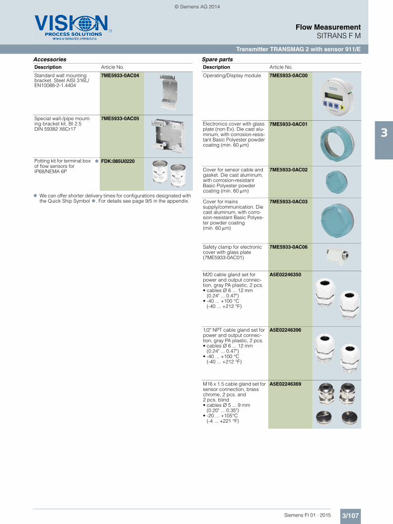
Strengthened mounting bracket for wall and pipeline installation
A02
Measuring range, specify in plain text:Y01: 0 to ... m3/h
Y01
Pulse significance, specify in plain text:Y02: 0 to ... pulses/l
Y02
Setting of digital outputs, specify in plain text:Y03: Setting of digital outputs: ...
Y03
Measuring-point number (max. 8 characters), specify in plain text: Y15: ..........
The rings must be ordered together with the sensor. In case of replacement please include the sensor MLFB code on the order.
911/E sensor
Process connection
Nominal diameters DN 15 ... 1000 (½" ... 40")
Metering tube connections EN 1092-1, ANSI B16.5, AWWA C-207 and JIS 10 K
Rated operating conditions
Installation conditions See system information
• Soft rubber liner 0 ... 70 °C (32 ... 158 °F)
• Hard rubber liner 0 ... 90 °C (32 ... 194 °F)Option: 100 °C (212 °F)
• PTFE liner • -20 ... +150 °C (-4 ... +302 °F) at 25 bar (363 psi)
• -20 ... +100 °C (-4 ... +212 °F) at 40 bar (580 psi)
• Linatex (rubber) liner -40 ... +70 °C (-40 ... +158 °F) (for temperatures below -20 °C (-4 °F) AISI 316L/1.4404 flanges must be used)
• Novolak liner 130 °C (266 °F) at 40 bar (580 psi)
Degree of protection IP67/NEMA 4XOptional IP68/NEMA 6
Medium conditions
Maximum flow velocity 12 m/s (39.4 ft/s)
Full scale value of flow velocity 0.15 ... 12 m/s (0.49 ... 39.4 ft/s)
Design
Weight See dimensional drawings
Flange and housing material Mild steel (1.0460/1.0570, with corrosion resistant two compo-nent epoxy coating (min. 150 m)orAISI 316L/1.4404 flanges and car-bon steel housing, with corrosion- resistant two-component epoxy coating (min. 150 m)
Measuring pipe material Stainless steel AISI 304 or higher
Grounding electrode material Defined via the Order code
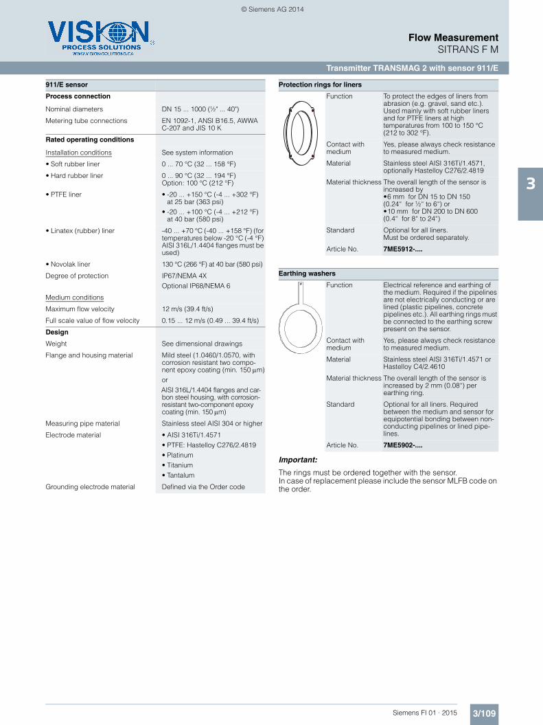
Protection rings for liners
Function To protect the edges of liners from abrasion (e.g. gravel, sand etc.). Used mainly with soft rubber liners and for PTFE liners at high temperatures from 100 to 150 °C (212 to 302 °F).
Contact with medium
Yes, please always check resistance to measured medium.
Material Stainless steel AISI 316Ti/1.4571, optionally Hastelloy C276/2.4819
Material thickness The overall length of the sensor is increased by •6 mm for DN 15 to DN 150(0.24“ for ½“ to 6“) or •10 mm for DN 200 to DN 600(0.4“ for 8“ to 24“)
Standard Optional for all liners. Must be ordered separately.
Article No. 7ME5912-....
Earthing washers
Function Electrical reference and earthing of the medium. Required if the pipelines are not electrically conducting or are lined (plastic pipelines, concrete pipelines etc.). All earthing rings must be connected to the earthing screw present on the sensor.
Contact with medium
Yes, please always check resistance to measured medium.
Material Stainless steel AISI 316Ti/1.4571 or Hastelloy C4/2.4610
Material thickness The overall length of the sensor is increased by 2 mm (0.08“) per earthing ring.
Standard Optional for all liners. Required between the medium and sensor for equipotential bonding between non-conducting pipelines or lined pipe-lines.
Article No. 7ME5902-....
FI01_2015_en_Kap03.book Seite 109 Dienstag, 14. Oktober 2014 9:17 09
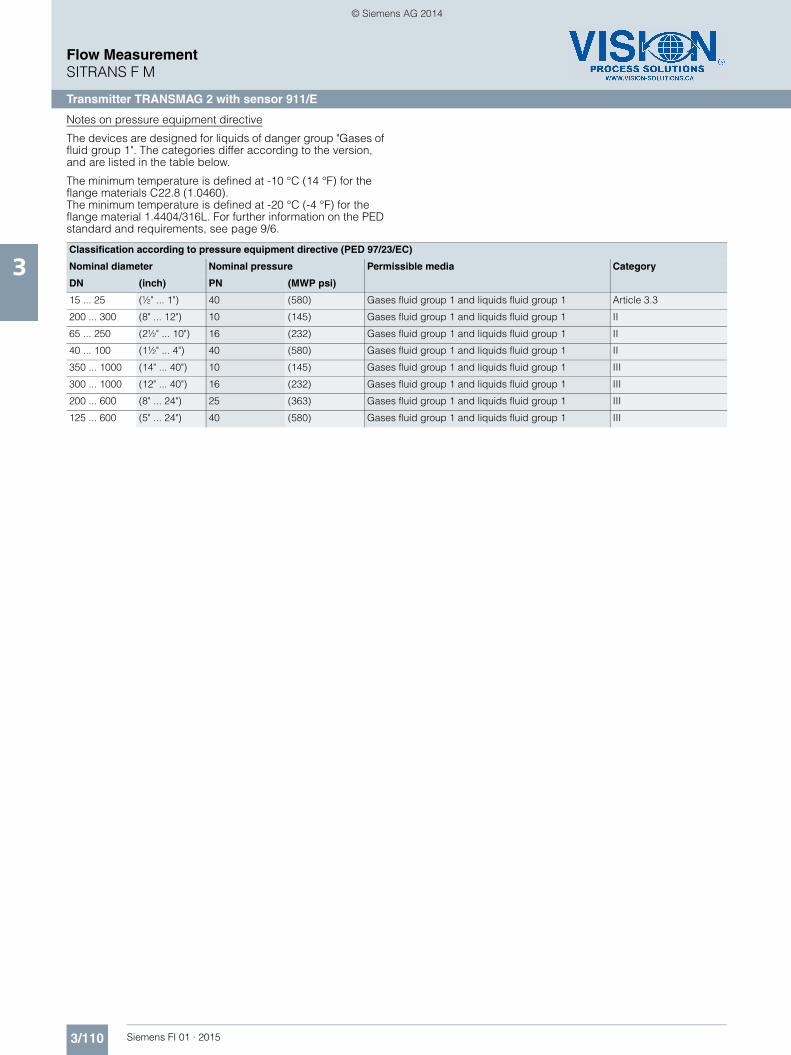
The devices are designed for liquids of danger group "Gases of fluid group 1". The categories differ according to the version, and are listed in the table below.
The minimum temperature is defined at -10 °C (14 °F) for the flange materials C22.8 (1.0460).The minimum temperature is defined at -20 °C (-4 °F) for the flange material 1.4404/316L. For further information on the PED standard and requirements, see page 9/6.
Classification according to pressure equipment directive (PED 97/23/EC)
Nominal diameter Nominal pressure Permissible media Category
DN (inch) PN (MWP psi)
15 ... 25 (½" ... 1") 40 (580) Gases fluid group 1 and liquids fluid group 1 Article 3.3
200 ... 300 (8" ... 12") 10 (145) Gases fluid group 1 and liquids fluid group 1 II
65 ... 250 (2½" ... 10") 16 (232) Gases fluid group 1 and liquids fluid group 1 II
40 ... 100 (1½" ... 4") 40 (580) Gases fluid group 1 and liquids fluid group 1 II
350 ... 1000 (14" ... 40") 10 (145) Gases fluid group 1 and liquids fluid group 1 III
300 ... 1000 (12" ... 40") 16 (232) Gases fluid group 1 and liquids fluid group 1 III
200 ... 600 (8" ... 24") 25 (363) Gases fluid group 1 and liquids fluid group 1 III
125 ... 600 (5" ... 24") 40 (580) Gases fluid group 1 and liquids fluid group 1 III
FI01_2015_en_Kap03.book Seite 110 Dienstag, 14. Oktober 2014 9:17 09
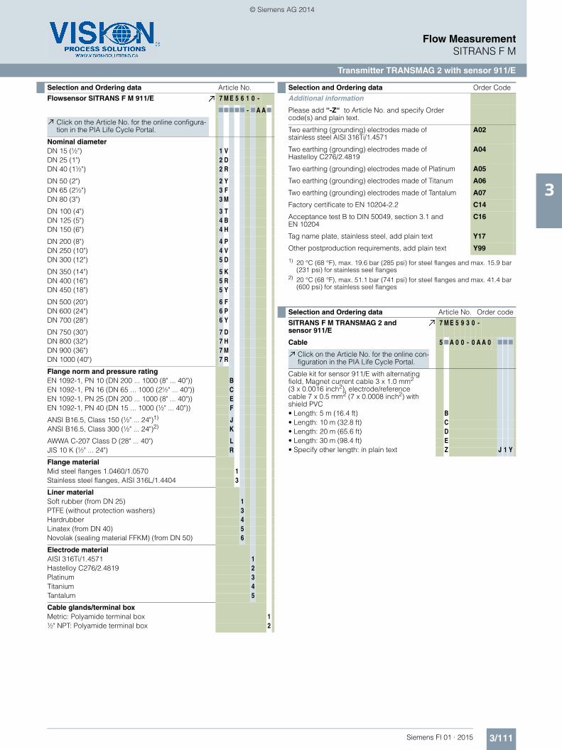
Please add “-Z“ to Article No. and specify Order code(s) and plain text.
Two earthing (grounding) electrodes made ofstainless steel AISI 316Ti/1.4571
A02
Two earthing (grounding) electrodes made of Hastelloy C276/2.4819
A04
Two earthing (grounding) electrodes made of Platinum A05
Two earthing (grounding) electrodes made of Titanum A06
Two earthing (grounding) electrodes made of Tantalum A07
Factory certificate to EN 10204-2.2 C14
Acceptance test B to DIN 50049, section 3.1 and EN 10204
C16
Tag name plate, stainless steel, add plain text Y17
Other postproduction requirements, add plain text Y99
Selection and Ordering data Article No. Order code
SITRANS F M TRANSMAG 2 and sensor 911/E
7 M E 5 9 3 0 -
Cable 5 7A 0 0 - 0 A A 0 777
Click on the Article No. for the online con-figuration in the PIA Life Cycle Portal.
Cable kit for sensor 911/E with alternating field, Magnet current cable 3 x 1.0 mm2 (3 x 0.0016 inch2), electrode/reference cable 7 x 0.5 mm2 (7 x 0.0008 inch2) with shield PVC• Length: 5 m (16.4 ft) B• Length: 10 m (32.8 ft) C• Length: 20 m (65.6 ft) D• Length: 30 m (98.4 ft) E• Specify other length: in plain text Z J 1 Y
FI01_2015_en_Kap03.book Seite 111 Dienstag, 14. Oktober 2014 9:17 09
SITRANS F M flow sensor 911/E, remote version, dimensions in mm (inch)
Build-in length 911/E [in mm and inch]
1) Tolerance for build-in lenght: L + 0.0/-4.0 mm (+0.00/-0.157 inch) With protection rings for > DN25 + 6.0 mm, > DN200 + 10.0 mm (> 1” + 0.236 inch, > 8” + 0.394 inch)