16
1 Flow Vision ™ I MX Gas Blending Station Alicat Scientific, Inc. 7641 N Business Park Drive Tucson, Arizona 85743 USA alicat.com

1
Flow Vision™ I MX Gas Blending Station
Alicat Scientific, Inc. 7641 N Business Park Drive
Tucson, Arizona 85743 USA
alicat.com

2
Notice: Alicat Scientific, Inc. reserves the right to make any changes and improvements to the products described in this manual at any time and without notice. This manual is copyrighted. This document may not, in whole or in part, be copied, reproduced, translated, or converted to any electronic medium or machine readable form, for commercial purposes, without prior written consent from the copyright holder.
Note: Although we provide assistance on Alicat Scientific products both personally and through our literature, it is the complete responsibility of the user to determine the suitability of any product to their application.
The manufacturer does not warrant or assume responsibility for the use of its products in life support applications or systems.
For more information regarding this or any Alicat product, please contact us at:
Alicat Scientific, Inc
7641 N Business Park Drive Tucson, Arizona 85743
USA
Ph: 520-290-6060 888-290-6060
Fax: 520-290-0109
email: [email protected] Web site: www.alicat.com
4/05/2016 Rev.4 DOC-FVISIONMXMAN
3
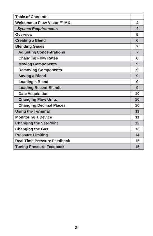
Table of Contents Welcome to Flow Vision™ MX 4 System Requirements 4
Overview 5 Creating a Blend 6 Blending Gases 7
Adjusting Concentrations 7 Changing Flow Rates 8 Moving Components 9 Removing Components 9 Saving a Blend 9 Loading a Blend 9 Loading Recent Blends 9 Data Acquisition 10 Changing Flow Units 10 Changing Decimal Places 10
Using the Terminal 11 Monitoring a Device 11 Changing the Set-Point 12 Changing the Gas 13 Pressure Limiting 14 Real Time Pressure Feedback 15 Tuning Pressure Feedback 15
4
Welcome to Flow Vision™ Gas Blending Station Flow Vision™ MX is a graphical software package that aides in the process of mixing gases. Currently, up to six Alicat Scientific, Inc. mass flow controllers are supported.
System Requirements Supported Operating Systems: Microsoft Windows Vista, Windows 7, Windows 8/8.1, Windows 10 • Software: Microsoft®.NET Framework Version 4.5.2 (A copy of Microsoft® .NET Framework can be downloaded at: https://www.microsoft.com/en-us/download/details.aspx?id=42642)
Hard Disk: Up to 10 MB of available space may be required for installation. Data logs may require additional space. Hardware: Available COM port, at least one Alicat Scientific, Inc. mass flow controller Display: Minimum of 860 x 860

5
Overview
1. Device Gas: The gas that the target device is set to flow. 2. Device Model Number: The model number of the target device. 3. Device Serial Number: The serial number of the target device. 4. Actual Mass Flow: The current mass flow measurement of the target device. 5. Device Set-Point: The current set-point (target flow) of the target device. 6. Actual Percent: The actual concentration percentage of the gas that the
target device is flowing. This will vary with the actual flow of all devices. 7. Target Percent: The target concentration of the gas in the overall blend. 8. Blend Composition: The makeup of the final gas blend. 9. Actual Total Flow: The total flow of the final gas blend. 10. Error: The flow error in terms of the target flow. 11. Maximum Flow: The maximum flow rate that can be reached. 12. Target Blend Flow Rate: The target rate of flow for the blend. 13. Start/Stop Mixing Button: Button to start/stop the mixing process. 14. Monitored Device: A device that is monitored during the mixing process. 15. Empty Location: An empty location that is available for mix components
or monitored devices.

6
Creating a Blend If you are not mixing, double click any of the six empty mix component locations. If you are already mixing, select File > New Blend from the menu to create a new, empty blend. Any existing blend information will be removed from the application. Double click any of the six empty mix component locations.
Select Mixing to add a device that will be used for gas mixing. Enter the following information:
Device Identifier: The alphabetic identifier of the device you wish to use. COM Port: The RS232 port that the device is connected to. Mix Percentage: The percentage of the final gas mix that this device will contribute. This can be changed later. Alarm at Pressure: If the pressure drops below this level Flow Vision™ MX will generate an alarm.
Click the “Add Mix” button to continue. Flow Vision™ MX will search for a mass flow controller using the selected parameters. If the device is found, it will be added to the current mix.

7
Blending Gases Adjusting Concentrations The concentration of each gas in the overall mix can be adjusted.
The gauge is split into tick marks for visual measurement of the flow (1). The indicator on the right of the gauge will match the percentage of the mixture (2). The percentage of the mixture can be edited directly in the box under the gauge (3).
Mixing cannot begin until the total of all concentrations reaches 100%. When this occurs, the “Start Mixing” button is enabled.
Devices that are at zero percent will not be represented in the final blend readings.
Controlling these devices outside of Flow Vision™ MX will create inaccurate blend readings.

8
Changing Flow Rates When the total of all concentrations reaches 100%, the “Start Mixing” button becomes enabled. Clicking this button will start the mixing process. The total flow of your gas blend can be changed adjusted.
The gauge is split into tick marks for visual measurement of the flow (1). The indicator on the right of the gauge (2) will match the total flow of the mixture. The total flow value can be edited directly in the box under the gauge (3). To stop the mixing process, click the “Stop Mixing” button. All device set-points will be set to zero and the gas flow will cease.

9
Removing Components To remove a component, left-click on the arrow in the top right of the item and select remove.
Saving a Blend Begin by selecting File > Save Blend from the menu. You will be prompted for a location on disc to store your blend. Enter a file name and click the “Save” button.
Blends are stored using the .fvb extension in XML format and can be modified using a text editor.
Loading a Blend Choose File > Load Blend from the menu to launch the open file dialog. Navigate to the desired blend file (.fvb) and click the “Open” button.
The stored blend will be loaded, overwriting any existing blends. Loading Recent Blends
Recent blends are added to the menu under File > Recent Blends. Selecting the blend name will load it into Flow Vision™ MX.
Components cannot be removed while blending.

10
Data Acquisition Flow Vision™ MX allows you to capture the data returned by the devices while mixing. To enable data acquisition, select File > Data Acquisition > Start from the menu or press the Ctrl + Q keys. To view the log files, select File > Data Acquisition > View Folder from the menu. Logs are stored with the date and time that the acquisition was started in the file name.
Changing Flow Units By default, all flow readings in Flow Vision™ MX are in SLPM. The units can be changed by selecting the desired units from the Edit > Flow Units menu.
Changing Decimal Places By default, all flow readings are shown to two decimal places.
Decimals can be increased or decreased using the Edit > Decimals menu.
Increasing the decimal places will not increase the resolution of the devices.

11
Using the Terminal The terminal allows for basic RS-232 communication with your Alicat Scientific™ devices while gases are being mixed. To launch the terminal, select View > Terminal from the main menu.
Select a valid port from the COM Port menu to begin communications. Commands are entered into the box at the bottom of the terminal.
Send a command by clicking the “Send” button. For more information on the standard Alicat Scientific™ command set or RS-232 communications, please see the operating manual for your device.
Monitoring a Device The device monitoring functionality allows you to interact with a device that may not be part of your current gas blend. Devices that are part of your blend may also be monitored. To add a device, double click any empty mix component location. Select Monitoring to add a device that will be used for monitoring. Enter the following information: Device Identifier: The alphabetic identifier of the device you wish to use. COM Port: The RS-232 port that the device is connected to. Click the “Add Device” button to continue.
Flow Vision™ MX will search for a device using the selected parameters. If the device is found, it will be added to the current mix.

12
Changing the Set-Point
The set-point on a monitored controller can be changed by clicking on the current set-point value. The field will become editable. Type in the desired set-point and press the Enter key. If the set-point is valid, it will be changed on the device.
Set-points cannot be changed while mixing.

13
Changing the Gas To change the gas of a monitored device, click on the current gas value.
Then select the desired gas from the list of available gases.
The gas cannot be changed while mixing. The selected gas should match the actual gas being flowed. If the gases do not match, flow readings will be inaccurate.

14
Pressure Limiting The pressure limiting feature of Flow Vision MX allows you to automatically stop mixing when a monitored pressure exceeds a set value. When pressure surpasses your preset limit, Flow Vision MX closes the valves on the mixing devices. When pressure drops below a low limit, mixing resumes.
Overview 1. Visual High Limit: A visual representation of the high limit. If the current pressure exceeds this, mixing will stop. 2. Visual Low Limit: A visual representation of the low limit. If the current pressure falls below this limit, mixing will resume. 3. Visual Current Pressure: A visual representation of the current monitored pressure. 4. Current Pressure: The current monitored pressure. 5. High Limit: An interactive representation of the high limit. 6. Low Limit: An interactive representation of the low limit. 7. Enable/Disable: Allows you to enable and disable the limit.
Adding a Pressure Limit Double click any of the six locations in the application. Select “Pressure Control” from the list of available options. Enter the following information: Device Identifier: The alphabetic identifier of the device that will be used to monitor pressure. COM Port: The RS-232 port that the device that will be used to monitor pressure is connected to. Click the “Add Device” button to continue. The pressure limiting view will be added to the application. Flow Vision MX will search for a device using the selected parameters. If the device is found, it will be added to the current mix.

15
Real Time Pressure Feedback Real time pressure feedback allows Flow Vision MX to control the flow of your gas mix based on a desired pressure. The application uses a control algorithm to adjust the flow of mix in real time to maintain pressure. To add a pressure feedback device, double click any empty mix component location. Select “Pressure Control” to add the device that will be used monitor pressure. Enter the following information: Device Identifier: The alphabetic identifier of the device you wish to use. COM Port: The RS-232 port that the device is connected to. Set-Point: The pressure that you would like to maintain, in the device’s pressure units. Click the “Add Device” button to continue.
Flow Vision MX will search for a device using the selected parameters. If the device is found, it will be added to the current mix.
Tuning Pressure Feedback
Flow Vision MX uses a modified PID control algorithm to maintain pressure at a set-point. The proportional (P) and derivative (D) terms can be adjusted by opening the Settings menu and changing the appropriate values. For more information on PID control and tuning, please see http://en.wikipedia.org/ wiki/PID_controller. While mixing with pressure feedback, Flow Vision will control the output of your mix. If you would like to disable this behavior, press the “Disable Feedback” button under the Settings menu.

Gas Viscosity, Density and Compressibility:
Flow Conversions:
SCFM 1.00 = 28.3160 SLPM SLPM 100.00 = 3.5316 SCFM SCFH 1.00 = 0.4719 SLPM SLPM 100.00 = 211.9093 SCFH SCIM 100.00 = 1.6390 SLPM SLPM 1.00 = 61.0128 SCIM SCIH 1000.00 = 0.2732 SLPM SLPM 1.00 = 3660.7688 SCIH
7641 N Business Park Drive
Tucson AZ 85743 USA Phone: 888-290-6060 Fax: 520-290-0109
alicat.com Innovative Flow and Pressure Solutions
# Gas Absolute Viscosity*
25°C
Density ** 25°C
14.696PSIA
Compressibility 25°C
14.696PSIA 20 75%Ar / 25% CO2 C-25 205.615 1.6766 0.9987 21 90% Ar / 10% CO2 C-10 217.529 1.6509 0.9991 22 92% Ar / 8% CO2 C-8 219.134 1.6475 0.9992 23 98% Ar / 2% CO2 C-2 223.973 1.6373 0.9993 24 75% CO2 / 25% Ar C-75 167.451 1.7634 0.9966 25 75% Ar / 25% He A-75 230.998 1.2660 0.9997 26 75% He / 25% Ar A-25 234.306 0.5306 1.0002
27
90% He / 7.5% Ar / 2.5% CO2
Helistar® A1025
A1025
214.840
0.3146
1.0003
28
90% Ar / 8% CO2 / 2% O2
Stargon® CS
Star29
218.817
1.6410
0.9992
29 95% Ar / 5% CH4 P-5 223.483 1.5850 0.9993 *in micropoise (1 Poise = gram / (cm) (sec)) **Grams/Liter Reference: NIST REFPROP 7 Database
# Gas Absolute Viscosity*
25°C
Density ** 25°C
14.696PSIA
Compressibility 25°C
14.696PSIA 0 Air Air 184.918 1.1840 0.9997 1 Argon Ar 225.593 1.6339 0.9994 2 Methane CH4 111.852 0.6569 0.9982 3 Carbon Monoxide CO 176.473 1.1453 0.9997 4 Carbon Dioxide CO2 149.332 1.8080 0.9949 5 Ethane C2H6 93.540 1.2385 0.9924 6 Hydrogen H2 89.153 0.08235 1.0006 7 Helium He 198.457 0.16353 1.0005 8 Nitrogen N2 178.120 1.1453 0.9998 9 Nitrous Oxide N2O 148.456 1.8088 0.9946 10 Neon Ne 311.149 0.8246 1.0005 11 Oxygen O2 204.591 1.3088 0.9994 12 Propane C3H8 81.458 1.8316 0.9841 13 normal-Butane n-C4H10 74.052 2.4494 0.9699 14 Acetylene C2H2 104.448 1.0720 0.9928 15 Ethylene C2H4 103.177 1.1533 0.9943 16 iso-Butane i-C4H10 74.988 2.4403 0.9728 17 Krypton Kr 251.342 3.4274 0.9994 18 Xenon Xe 229.785 5.3954 0.9947 19 Sulfur Hexafluoride SF6 153.532 6.0380 0.9887


