KONA No.24 (2006) 146 1. Introduction Today, flowsheeting program packages are com- monly used in chemical engineering for the design of processes involving fluids (e.g. 1)). There are several established systems for the simulation of fluid pro- cesses. Among these are, for example, Aspen plus 2) , Pro/II 3) or Chemcad 4) . The simulation of processes which involve solids is not as advanced, but it is common practice to de- sign and optimise each apparatus separately from the others, neglecting its influence and dependence on the neighbouring processes. For simulation of the process, mathematical models for the individual units are used and the results are transferred manually from unit to unit. While this is feasible without sig- nificant loss of information for several units in series, it fails if there is a recycle loop which feeds back an outlet stream of one unit into another unit placed up- stream. In that case, the simulation of the whole flow- sheet has to be done iteratively, which is not or only in a very limited way possible by manual sequencing. In each case, simulating a process by this method is quite a time-consuming process. Furthermore, the simulation unit by unit permits finding optimal operating conditions for each unit operation or apparatus. But such a sequential optimi- zation of individual units will not necessarily lead to a global optimum for the whole process. The reason for the gap between the simulation of fluid and of solids processes is basically the need for a more complex description of the solids. In addition to the parameters needed to characterise a fluid, for solids the dispersity has to be described, e.g. by the particle size. The description of the dispersity usu- ally requires a distributed parameter, thus increasing the complexity of the information to be transferred between the different units of a flowsheet. A more de- tailed discussion of this problem will be given in the Flowsheet Simulation of Solids Processes † E.U. Hartge, M. Pogodda, C. Reimers, D. Schwier, G. Gruhn and J. Werther Institute of Solids Process Engineering and Particle Technology Technical University Hamburg-Harburg* Abstract Flowsheeting program packages are now commonly used in chemical engineering for the design of processes involving fluids. The simulation of processes which involve solids or solids and fluids is not as advanced. In solids processing it is still common practice to design one apparatus separately from the other. There is a lack of suitable methods to combine single apparatus models to form a process and to treat this process as a whole. With the program package ‘SolidSim’, a simulation system especially designed for the simulation of processes including solids has been developed. At the present state of development, modules are available for classification, particle size reduction, crystallisation and dissolution, liquid-solid separation, gas-solid separation, agglomeration, reaction, drying, conveying and different general modules. The structure of the system is explained in detail and the application to a process for the treatment of contaminated sludge is shown. Keywords: Solids process, Flowsheet simulation † Accepted : August 14, 2006 * 021073 Hamburg-Harburg, Deniekesh, 15, Germany 1 Corresponding author TEL: +49-40-428783039, FAX: +49-40-428782678 Email: [email protected]
Transcript
KONA No.24 (2006)146
1. Introduction
Today, flowsheeting program packages are com-monly used in chemical engineering for the design of processes involving fluids (e.g. 1)). There are several established systems for the simulation of fluid pro-cesses. Among these are, for example, Aspen plus 2), Pro/II 3) or Chemcad 4). The simulation of processes which involve solids is not as advanced, but it is common practice to de-sign and optimise each apparatus separately from the others, neglecting its influence and dependence on the neighbouring processes. For simulation of the process, mathematical models for the individual units are used and the results are transferred manually from unit to unit. While this is feasible without sig-
nificant loss of information for several units in series, it fails if there is a recycle loop which feeds back an outlet stream of one unit into another unit placed up-stream. In that case, the simulation of the whole flow-sheet has to be done iteratively, which is not or only in a very limited way possible by manual sequencing. In each case, simulating a process by this method is quite a time-consuming process. Furthermore, the simulation unit by unit permits finding optimal operating conditions for each unit operation or apparatus. But such a sequential optimi-zation of individual units will not necessarily lead to a global optimum for the whole process. The reason for the gap between the simulation of fluid and of solids processes is basically the need for a more complex description of the solids. In addition to the parameters needed to characterise a fluid, for solids the dispersity has to be described, e.g. by the particle size. The description of the dispersity usu-ally requires a distributed parameter, thus increasing the complexity of the information to be transferred between the different units of a flowsheet. A more de-tailed discussion of this problem will be given in the
Flowsheet Simulation of Solids Processes†
E.U. Hartge, M. Pogodda, C. Reimers, D. Schwier, G. Gruhn and J. WertherInstitute of Solids Process Engineering and Particle Technology Technical University Hamburg-Harburg*
Abstract
Flowsheeting program packages are now commonly used in chemical engineering for the design of processes involving fluids. The simulation of processes which involve solids or solids and fluids is not as advanced. In solids processing it is still common practice to design one apparatus separately from the other. There is a lack of suitable methods to combine single apparatus models to form a process and to treat this process as a whole. With the program package ‘SolidSim’, a simulation system especially designed for the simulation of processes including solids has been developed. At the present state of development, modules are available for classification, particle size reduction, crystallisation and dissolution, liquid-solid separation, gas-solid separation, agglomeration, reaction, drying, conveying and different general modules. The structure of the system is explained in detail and the application to a process for the treatment of contaminated sludge is shown.
following sections of the paper. While most of the simulation systems for fluid processes also offer some basic support for the simu-lation of solids processes, they are mostly used ex-clusively for the simulation of fluid processes. On the other hand, there are some specialised flowsheet sim-ulation systems for solids processes, e.g. USimPac5), JKSimMet6), PMP FBSim7), SoProSim8), AggFlow9), Rockworks10) and METSIM11). These packages are ei-ther limited to physical non-thermal and non-reactive processes or to quite narrow industrial sectors, e.g. ore or earth processing or metallurgy. Quite often the interaction between the solids and the surrounding fluid is neglected. Against this background, the simulation program SolidSim was developed by a group of 11 institutes from 9 German universities. The aim of this develop-ment was a generally applicable flowsheet simulation system, providing all the structures necessary for the description of solids and the simulation of solids pro-cesses, including physical treatment, thermal treat-ment and also for reactions. The system should not be restricted to solids processes only, but it should also be possible to extend the system towards fluid processes. Further requirements were easy handling via a graphical user interface and the interoperabil-ity with other simulation systems. The latter was achieved by implementing a standardised interface as defined by the Cape Open Laboratory Network (CO-LaN,12)). At the moment, the simulation package is for steady-state simulation only.
2. Simulation of Solids Processes
The most obvious difference to the simulation of fluid processes is the necessity of using distributed attributes to describe solids. The most important but not the only attribute is the particle size. The intro-duction of a distributed parameter, which usually has to be discretized, increases the number of variables by an order of magnitude or even more. Since the fate of a particle in many processes de-pends on its particle size, some other parameters describing the particle may depend on the particle size. For example, when particles are dried in a dryer with a perfect plug flow of solids, the remaining hu-midity inside a particle will depend on the particle size, unless all particles are completely dried. Large particles will have a higher moisture content than the smaller ones. Thus, we need the moisture content as a particle-size dependent attribute. To extend the example of the dryer, we may now assume that there
is no plug flow of the solids, but for the solids the dryer might behave like a stirred tank. In that case the particles of each particle size will underlie a res-idence-time distribution. The particles with a short residence time will have quite a high residual mois-ture, while particles of the same particle size which stay for a longer period in the dryer will have a lower moisture content. Thus, the moisture content in each individual class will be a distributed parameter. This distribution of the moisture content will again be size-dependent as the average moisture of the fines will be lower than that of the coarse particles. Similar secondary distributions will result if the particle un-dergoes a reaction. While for the drying example, the secondary dis-tribution might not be very important and could be replaced by average values, for the processing of ores, the content of metal in the ore as a secondary attribute could be crucial for the whole concentrating process. Generally, in flowsheeting simulation programs different phases are distinguished. Here, the term phase is defined as ‘a stable or metastable collec-tion of compounds with a homogeneous composi-tion, which can be distinguished from other phases through the presence of physical interfaces that sepa-rate states of matter with different characteristics, such as density. Each phase has an associated state of aggregation, i.e. gaseous, liquid or solid’13). The requirement of a physical interface allows multiple liquid phases, e.g. oil and water, but only one gaseous phase. Also for solids, a physical interface can hardly be defined. Therefore all different types of solids be-long to the same phase and the type of solid is only one more attribute in the attribute hierarchy. Looking onto the stream of solids entering an apparatus, this makes sense. For example, a gas cyclone does not distinguish between different types of solids as long they have the same size and density, or, to be more precise, the same terminal velocity. It would make no sense to feed the different types of solids one after the other to the cyclone model, since they interact and will influence each other. The cyclone model does not even require the information on the solids type; it needs only information about the terminal velocity. While the model of the cyclone will calculate the separation according to this primary attribute, there is also an implicit change of the other depen-dent attributes. If a compound A consists of heavier and larger particles than a second compound B, compound A will be enriched in the underflow of the cyclone, while compound B will be enriched in the
KONA No.24 (2006)148
fines carried out together with the gas. This implicit change of any dependent attribute has to be calcu-lated by the system. As for the example of the gas cyclone, it is a gen-eral problem when dealing with mixtures of solids that most models of apparatus or unit operations for solids are derived for one type of solids with a con-stant density only. For classification processes, the particle size is then usually used as the dispersity attribute to which separation rates are assigned. But examination of the physical mechanism of the clas-sification process often yields that it is not the size that is the governing parameter, as in the case of the gas cyclone, but the terminal velocity. To allow simu-lation of the classification of mixtures of solids, the models therefore have to be rewritten such that the fractional separation efficiency is indeed a function of the governing parameter. Only if there is no interac-tion between the particles, a model can be taken as published and the different types of solids can be fed individually to the model and be mixed again at the outlet.
3. Structure of Solidsim
Generally, flowsheet simulation programs may be classified into two groups, block-oriented programs and equation-oriented programs. The former re-semble the manual sequencing of individual models for the different units as described above, but with automation of the information transfer between the blocks. Loops are solved iteratively by calculating the units or blocks within the loop repeatedly. The equation-oriented systems put all the model equa-tions for the different units of a flowsheet into one big equation system and solve the whole system with a suitable solver. The block-oriented approach has the disadvantage that it cannot be used for dynamic simulations due to excessive computing times. On the other hand, the equation-oriented approach puts high demands on the solver. For fluid processes, the equation systems may already become very large with several tens of thousands of variables and equations. With the dis-tributed attributes necessary for solids processes, the size of the equation system will increase even more, reaching the limits of computational resources available today. Even more important, the inclusion of population balances will change the nature of the equation system to a system of partial and ordinary integro-differential equations14). Up to now for very large systems of this type, no generally applicable
solvers are available. This forced the decision to de-sign SolidSim as a block-oriented system.The program system is divided into four major parts: ・ the simulation environment, which provides the
basis of the whole system, ・ the stream objects, which transport and manage
the inserted stream information and ・ the model library with the unit models, ・ the property package, that provides the physical
data and the phase equilibrium for the materials in the stream objects.
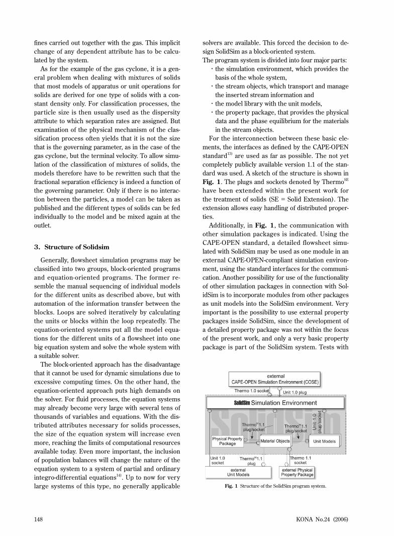
For the interconnection between these basic ele-ments, the interfaces as defined by the CAPE-OPEN standard13) are used as far as possible. The not yet completely publicly available version 1.1 of the stan-dard was used. A sketch of the structure is shown in Fig. 1. The plugs and sockets denoted by ThermoSE have been extended within the present work for the treatment of solids (SE = Solid Extension). The extension allows easy handling of distributed proper-ties. Additionally, in Fig. 1, the communication with other simulation packages is indicated. Using the CAPE-OPEN standard, a detailed flowsheet simu-lated with SolidSim may be used as one module in an external CAPE-OPEN-compliant simulation environ-ment, using the standard interfaces for the communi-cation. Another possibility for use of the functionality of other simulation packages in connection with Sol-idSim is to incorporate modules from other packages as unit models into the SolidSim environment. Very important is the possibility to use external property packages inside SolidSim, since the development of a detailed property package was not within the focus of the present work, and only a very basic property package is part of the SolidSim system. Tests with
Fig. 1 Structure of the SolidSim program system.
KONA No.24 (2006) 149
the program package ASPEN+(12.1) of Aspentech have been carried out successfully. The connection with property packages via the Cape-Open interfaces has been tested with Aspen Properties15), Infochem’s Multiflash16) and with Simulis Thermodynamics17); all packages have been used successfully to provide the fluid data necessary for simulation.
The Material Stream Object
One major development task in the present work was the development of the stream objects, i.e. the structures to store the current status of a material stream connecting two subsequent models or units in the flowsheet. The stream objects have to provide the models with all properties of the incoming materials, i.e. fluids and solids. The schematic structure of the material stream object is depicted in Fig. 2. The ma-terial stream is described by overall properties such as temperature, pressure and total flow. The matter of the stream is divided into different phases each characterised by an ID and the state of aggregation. Required properties are the phase fraction (concen-trated) and the composition (distributed). In addition, further phase properties can be defined as either concentrated or distributed. A typical distributed property is the particle size distribution, while e.g. the density will typically be a concentrated parameter. In some cases, however, the density might also be a distributed parameter, e.g. in the case of soil, which in detail consists of dif ferent materials, but which
may be treated within the simulation system as one single compound. In general, the user has to decide for each attribute whether it is necessary to describe it by a distribution or if it is sufficient to use a single value as a concentrated parameter. The system is not restricted to a limited list of properties, but the user is allowed to introduce any new property to the sys-tem, as long as at least one unit model makes use of this property. While for the implementation of the fluid part and for the storage of concentrated properties existing approaches could be used, the implementation of the solids part with the distributed properties had to be newly developed. The design goal was a structure which allows the efficient storage of and access to complex hierarchies of nested and dependent distributed solids proper-ties. In addition, the stream object should be able to provide the information to the unit models in an appropriate manner, i.e. it should only give the infor-mation needed by the module, hiding all additional complexity. For the storage and access of a hierarchy of attri-butes a tree structure is often used. But this kind of structure requires rearrangement of the tree if the hi-erarchical dependencies change. Since during a sim-ulation run, the hierarchical structure changes from unit to unit, this causes a significant computational overhead. Therefore, instead of the tree structure, the data in SolidSim is stored in an n-dimensional ma-trix, with n being the number of dependent attributes. As an example, a matrix for three distributed attri-butes (i, j, k) is shown in Fig. 3. In this matrix, each cell represents the mass fraction ΔQ3 of the matter of a phase that can be described by the combination of the different property classes. The highlighted cell represents the mass fraction of all particles which can be described by the 2nd class of attribute i, the 5th class of attribute j and the 1st class of attribute k.
Fig. 2 Structure of the material stream object.Fig. 3 Matrix-representation of distributed properties. As an example,
the mass fraction ΔQ3(2,5,1) is shown as a shaded square.
→
←
→
KONA No.24 (2006)150
For the sum of all entries in the matrix, it holds that.
∑ ΔQ3(i, j, k)=1 (1)
This structure allows access to all combinations of attributes in any arbitrary sequence without any re-sorting. As a solution for the problem of attributes being im-plicitly changed between entrance and outlet of a unit as described above for the example of a gas cyclone, a movement matrix has been introduced. Instead of directly writing the changed attributes to the outlet streams, taking care of all dependent attributes, the unit model only has to fill a movement matrix, which includes only attributes which are explicitly changed. The dimension of the movement matrix is equal to two times the number of explicitly changed attri-butes. For the example of the cyclone, the explicitly changed attribute would be the terminal velocity only, thus the dimension of the morement matrix is equal to two. In cases where only one attribute is explicitly changed, the movement matrix is a square matrix (c.f. Fig. 4) quite similar to a breakage matrix known from comminution. It assigns the material in a cer-tain class at the inlet to any of the defined classes at the outlet. For a classification, only the fields on the diagonal will be filled, all the other fields will be zero. The values Ti,j with i = j on the diagonal are the frac-tional separation efficiencies. For size reduction, the matrix will have non-zero values only in the lower left triangle (Ti,j with i ≥ j ), for an agglomeration process, only the upper right half (Ti,j with i < j ) will be filled with non-zero values. Only the transformation matrix is computed by the model of a unit and then passed back to the material stream object. This will apply the transformation matrix to the whole attribute matrix,
thus ensuring that all implicit changes of dependent attributes are correctly calculated.
Model Library
The model library is basically a collection of inde-pendent software modules containing one or several models for a certain apparatus or a unit operation. For each apparatus, models of different complexity and different requirements with respect to the input data are used. This allows the use of different models in different stages of the design process, e.g. in an early design phase quite simple models which need only a few data that are easy to measure or estimate, and more complex models with higher requirements with respect to the data to simulate or optimise an existing plant. Models from the open literature have been selected for implementation. The models have been chosen together with experts from industry, based on their experience with the models applied to industrial units. Most of the models had to be rewrit-ten such that they depend on the parameters which really determine the physical process, e.g. as men-tioned above, the models for gas cyclone and hydro-cyclone have been rewritten to employ the terminal velocity as the independent parameter instead of the combination of particle size and density. While in fluid processing the absolute geometry of an apparatus usually has only a minor effect on the result and is therefore neglected in most simu-lations systems, for many of the solids-processing units, the geometry directly affects the result of the process; for example the cut size of a gas cyclone is not only affected by the velocities and solids loading, but depends directly on the absolute diameter of the cyclone. Due to this influence, most of the modules require information about the geometry of the appa-ratus, in some modules even two calculation modes are implemented, one with a user-defined absolute geometry (simulation mode) and another in which the geometry is calculated by the module itself (de-sign mode). The software modules were implemented as COM objects, so that they can be added and removed dur-ing runtime. They communicate with the simulation environment via the Cape-Open Unit 1.0 plug/socket and with the connected streams via the extended ThermoSE 1.1 plug and socket (Figs. 1, 5). The Unit 1.0 interface is mainly used to control the program logic and execution sequence, the ThermoSE 1.1 interface is used to query all information about the materials involved. In the case of solids processes, Fig. 4 Structure of a movement matrix
KONA No.24 (2006) 151
additional information, e.g. on the geometry of the apparatus is usually necessary; such information has to be queried from the user by the user interface provided by each module. Usually only parameters purely related to the apparatus should be queried this way. Since some models rely on parameters which are a combination of material properties and machine parameters, this rule cannot be followed strictly. In such cases, these combined parameters also have to be queried from the user. In order to facilitate the development of unit mod-els, a ‘base unit class’ has been implemented which forms the common basis of all the modules (Fig. 5). The task of this base unit is twofold. First it should hide all implementation details for the communica-tion between the different software components from the engineering-oriented developer of the unit model. The second task is to provide and ensure a mini-mal functionality, e.g. to copy input to output streams, to check mass balances, to provide methods for con-necting streams to the ports of the apparatus, etc. In the simplest case, the model implementer should only have to implement specific calculation and ini-tialisation routines and to provide some basic infor-mation about entrance and exit ports. The model library is still far from being complete, but it already covers the most important areas of par-ticle technology. It contains modules for classification and separation, size reduction and size enlargement, drying, particle generation by crystallization and also for a gas-solids reactor. Table 1 gives a list of solids processing steps for which models have been developed together with the name of the responsible project partner. The implementation of further solids processing steps as independent modules is either planned or already in progress. Another possibility to extend the model library is to create aggregate units. These aggregate units combine existing modules as a sub-flowsheet, which afterwards can be used as a new unit model. This ap-
proach allows, for example the creation of a module for a circulating fluidised bed simply by combining a fluidised-bed module with the cyclone module. An-other example which has already been tested is the creation of a module of a classifier mill, which has been simulated by the combination of a crusher and a sifter.
4. Application of Solidsim
The application of the developed system shall be demonstrated with two examples. The first one, a closed grinding circuit, is quite simple. It consists of only two units and needs as the only attributes the material and the particle size distribution to describe the solids. The second example is a process for the physical treatment of contaminated sludge. This example is much more complex, it consists of 9 ma-jor units plus several auxiliary units such as mixing points, splitters and pumps. Furthermore, a control-ler is involved.
Simulation of a Closed Grinding Cicuit Size reduction is usually done in a closed circuit, i.e. a combination of a mill or crusher and classifier, which sends the coarse material back to the size re-duction step. This combination of the size reduction unit and the classification unit might either consist of two independent units or alternatively one single unit. Fig. 6 shows a screenshot of SolidSim with a flow-sheet of a closed milling circuit. The feed is coal with a particle size distribution ranging from about 50μm to 10 mm as shown in the screenshot. The sieve has a mesh width of 0.8 mm, the mill used in this example
Fig. 5 Internal structure and interfaces of a unit model.
inputstream (s)
ThermoSE 1.1socket
geometrydata
outputstream (s)
ThermoSE 1.1plug
(user interface)stream data / properties
specific model
base unit
simulation environmentUnit 1.0plig/socket
done
calculate
unit model Table 1 Solids processing modules in SolidSim
Processing step Responsible partnerSeparation, classification Werther, HamburgFiltration of fluids Ripperger, KaiserslauternGas filtration E. Schmidt, WuppertalSeparation processes in centrifuges
Stahl & Nirschl, Karlsruhe
Agglomeration, granulation Mörl, Magdeburg
Crushing in mills Peukert, ErlangenConvection drying Tsotsas, MagdeburgCrystallisation, dissolving Kind, KarlsruheGas-solid reactions in fluidised beds
Werther, Hamburg
Liquid spraying Walzel, DortmundDosing and conveying Wirth, Erlangen
KONA No.24 (2006)152
is a hammer mill. The model used for the simulation of the hammer mill is based on the work by Vogel and Peukert18), 19), the description of the classification with the sieve is based on a classification function by20). A detailed description of the models can be found in21). The parameterization dialog of the mill
can be seen in Fig. 7. It takes about 30s to iteratively solve this problem. The results of the simulation are as shown in Figs. 8 and 9. In Fig. 8, the particle size distribution of the product is plotted, whereas Fig. 9 gives an overview on the different streams in the flowsheet. In this case
Fig. 7 Screen shot of SolidSim with a closed milling circuit.
Fig. 6 Parameterization of the module “hammer mill”
KONA No.24 (2006) 153
the total mass flow, the mass flow of solids (which is equal to the total mass flow since no fluid has been defined) and the medium particle size x50 (last col-umn) for all the streams are shown. The simulation yields that the recycle stream has a mass flow nearly twice the size of the feed mass flow. Using the SolidSim system for this simulation allows the configuration of the circuit to be easily changed. While in the first version of the circuit, the feed enters the mill first, for the second version as shown in Fig. 10, the feed flow enters the sieve first,
thus removing the fines before entering the mill. The calculated results are shown at the bottom of Fig. 10. The simulations show that in this case, the flow through the mill is slightly reduced, while the throughput through the sieve is increased. In addi-tion, the PSD of the product is changed minimally; the product has a slightly higher medium size x50.
Simulation of a Soil Washing Process
As a second, more complex example, SolidSim has been applied to a special soil washing process, namely the physical treatment of contaminated har-bour sludge. The process has been developed by the authors’ group which has been in operation in Hamburg 22, 23) for several years. This process takes advantage of the fact that the extent of contamination
Fig. 10 Modified circuit with screenshot of the stream overview.
Fig. 11 Size-dependent contamination of dredged sludge (harbour of Hamburg) with lead. On the right side, the cumulative mass distribution of the particle size is plotted.
Fig. 9 Result of the simulation of the flowsheet according to Fig. 6, screenshot of the stream overview.
Fig. 8 Result of the simulation of the flowsheet according to Fig. 6, particle size distribution of the product.
KONA No.24 (2006)154
depends on the particle size. This is illustrated in Fig. 11. In the right-hand part of the graph, the cumula-tive mass distribution of the particle size is plotted. On the left side, the contamination of the different particle size classes is shown. It can be seen that the fraction of particles with a size below 25μm making up about 35% of the mass has a lead concentration of about 160 ppm. The area of the bars in the left part of the diagram is proportional to the mass fraction of contaminants of the respective class in the total contamination. Thus, removing the fine particles with dp < 25μm will remove only about 35% of the mass but more than 80% of the contamination, resulting in a highly contaminated fraction of fines and a coarse fraction with a low concentration of lead. The technical process for this classification and dewatering as it is employed in Hamburg is shown in Fig. 12. It consists of several sieves, hydrocyclones, an elutriator, screen belt presses and some other units. The models used for the simulation of the dif-ferent units may be found in reference 21). With the fairly large number of units and several recycles of the process water with fines, this process is certainly too complex for manual simulation. Furthermore, it demonstrates the use of a dependent attribute which is in this case the particle-size-dependent contamina-tion. Simulation with SolidSim allows prediction of the influence of changes of operating conditions or the influence of a change of a single unit on perfor-mance of the whole process. It also allows finding suitable operating parameters to keep the sand fractions below given contamination
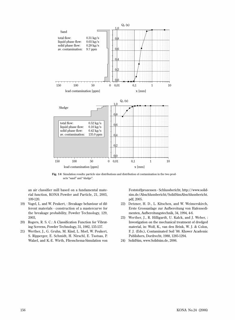
limits when the dredged sludge changes or even to improve the process by performing several simula-tion runs with variations of the operating parameters or of the flowsheet itself. Up to now, no mathematical optimization feature is implemented, but the struc-ture of the program allows for a respective extension of the system in the future. Fig. 13 shows a screenshot of SolidSim with the flowsheet of the process. The process has been simu-lated with a mass flow at the entrance of 9 kg/s fluid and 1 kg/s solids. Fig. 14 shows as results of the simulation the particle size distribution and the dis-tribution of the lead contamination for both the sand fraction and the sludge. The results show that 52% of the solids fed to the process remain in a highly contaminated “sludge” product, while the remaining 48% are collected in the less contaminated products “coarse material”, “sand”, and “fine sand”. These latter materials may be reused for road building or other purposes, whereas the sludge has to be dumped in a landfill for hazardous waste. The separation process reduces the required disposal volume by roughly 50%.
5. Conclusions
The complex description of solids with their distributed and dependent attributes puts special demands on systems for flowsheet simulation. With the package SolidSim, a system has been developed that meets these requirements. It is the result of the joint effort of specialists from university and indus-
Fig. 12 Flowsheet for the mechanical dewatering and separation of harbour sediments.
KONA No.24 (2006) 155
try. First applications with complex solids processes show its ability to support the engineer in designing and improving solids processes. At the moment, the system is not yet in a marketable state. It needs some improvement in stability and also a further extension of the model library. This further development of the system is in progress with the financial support of an industrial consortium 24).
Acknowledgements
Financial support of this work by the Association of Industrial Research Institutions (Arbeitsgemein-schaft industrieller Forschungsvereinigungen - AiF) under grant no. 94 ZBG/1-12 and by the industrial consortium IK SolidSim is gratefully acknowledged.
Bibliography
1) Seider, W. D., J. D. Seader, and D. R. Lewin, : Process design principles: synthesis, analysis and evaluation: John Wiley & Sons, 1999.
htm, 2006.8) Wilichowski, M., T. Pawletta, : SoProSim - A Tool for
the flowsheet-orientated Simulation of Classification Processes, in: Pratsinis, S. E., Schulz, H., Strobel, R. & Schreglmann, C. (Eds.), Proceedings of International Congress for Particle Technology PARTEC 2004.Nuremberg: 2004, Proceedings on CD.
18) Vogel, L. and W. Peukert, : Modelling of grinding in
Fig. 13 SolidSim flowsheet for the mechanical dewatering and separation of harbour sediments.
KONA No.24 (2006)156
an air classifier mill based on a fundamental mate-rial function, KONA Powder and Particle, 21, 2003, 109-120.
19) Vogel, L. and W. Peukert, : Breakage behaviour of dif-ferent materials - construction of a mastercurve for the breakage probability, Powder Technology, 129, 2003,
20) Rogers, R. S. C.: A Classification Function for Vibrat-ing Screens, Powder Technology, 31, 1982, 135-137.
21) Werther, J., G. Gruhn, M. Kind, L. Morl, W. Peukert, S. Ripperger, E. Schmidt, H. Nirschl, E. Tsotsas, P. Walzel, and K.-E. Wirth, Fliesschema-Simulation von
22) Detzner, H. D., L. Kitschen, and W. Weimerskirch, Erste Grossanlage zur Aufbereitung von Hafensedi-menten, Aufbereitungstechnik, 34, 1994, 4-6.
23) Werther, J., R. Hilligardt, U. Kalck, and J. Weber, : Investigation on the mechanical treatment of dredged material, in: Wolf, K., van den Brink, W. J. & Colon, F. J. (Eds.), Contaminated Soil ’88. Kluwer Academic Publishers, Dordrecht, 1988, 1285-1294.
24) SolidSim, www.Solidsim.de, 2006.
Fig. 14 Simulation results: particle size distributions and distribution of contamination in the two prod-ucts “sand” and “sludge”.
KONA No.24 (2006) 157
Author’s short biography
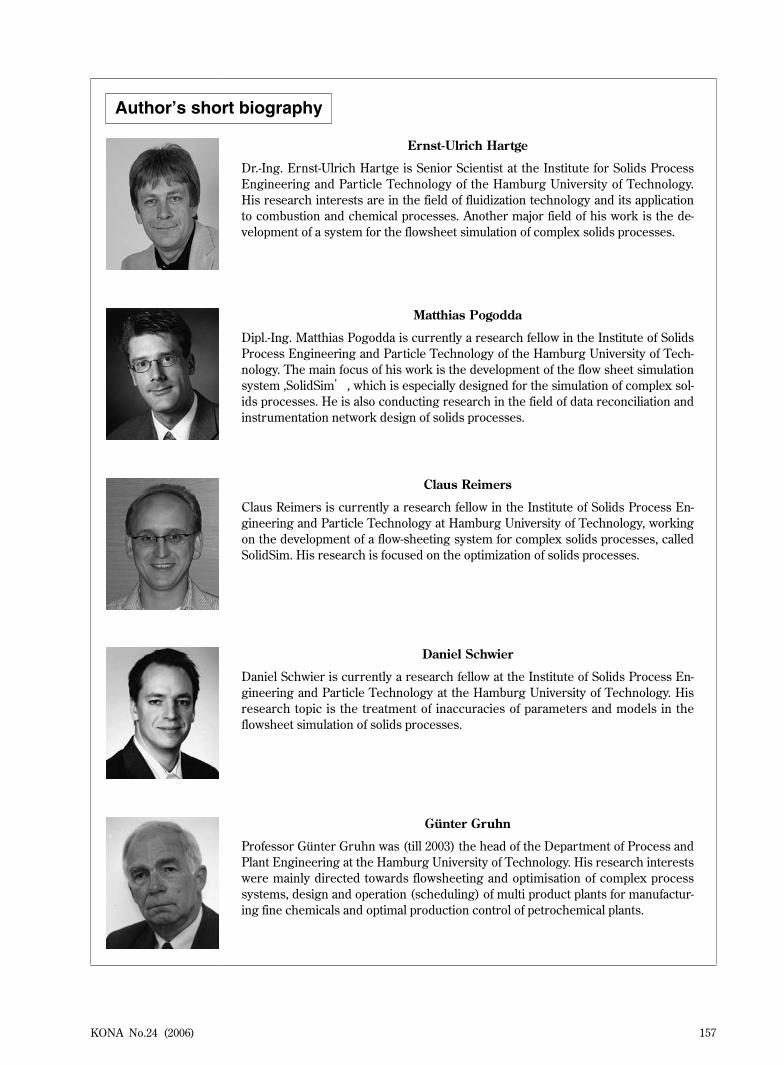
Ernst-Ulrich Hartge
Dr.-Ing. Ernst-Ulrich Hartge is Senior Scientist at the Institute for Solids Process Engineering and Particle Technology of the Hamburg University of Technology. His research interests are in the field of fluidization technology and its application to combustion and chemical processes. Another major field of his work is the de-velopment of a system for the flowsheet simulation of complex solids processes.
Matthias Pogodda
Dipl.-Ing. Matthias Pogodda is currently a research fellow in the Institute of Solids Process Engineering and Particle Technology of the Hamburg University of Tech-nology. The main focus of his work is the development of the flow sheet simulation system ‚SolidSim’, which is especially designed for the simulation of complex sol-ids processes. He is also conducting research in the field of data reconciliation and instrumentation network design of solids processes.
Claus Reimers
Claus Reimers is currently a research fellow in the Institute of Solids Process En-gineering and Particle Technology at Hamburg University of Technology, working on the development of a flow-sheeting system for complex solids processes, called SolidSim. His research is focused on the optimization of solids processes.
Daniel Schwier
Daniel Schwier is currently a research fellow at the Institute of Solids Process En-gineering and Particle Technology at the Hamburg University of Technology. His research topic is the treatment of inaccuracies of parameters and models in the flowsheet simulation of solids processes.
Günter Gruhn
Professor Günter Gruhn was (till 2003) the head of the Department of Process and Plant Engineering at the Hamburg University of Technology. His research interests were mainly directed towards flowsheeting and optimisation of complex process systems, design and operation (scheduling) of multi product plants for manufactur-ing fine chemicals and optimal production control of petrochemical plants.
KONA No.24 (2006)158
Joachim Werther
Professor Joachim Werther is the head of the Institute of Solids Process Engineer-ing and Particle technology at the Hamburg University of Technology. His research interests are mainly directed towards fluidization technology and its application for industrial processes, towards classification of particles and towards the physical treatment of contaminated solids. A further major field of research is the develop-ment of advanced simulation tools for the flowsheet simulation of processes involv-ing solids.