20
FLOWSIC600-XT THE PERFECT MATCH Gas flow meters PRODUCT INFORMATION
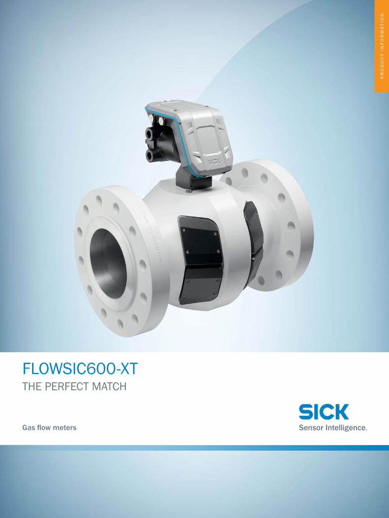
FLOWSIC600-XTTHE PERFECT MATCH
Gas flow meters
PR
OD
UC
T I
NF
OR
MA
TIO
N

8018938/2015-10Subject to change without notice
2 U l t r a s o n i c g a s f l o w m e a s U r i n g d e v i c e s | s i c K
FLOWSIC600-XT: THE PERFECT MATCHJust how can the market leader for reliable, maximum precision ultrasonic gas flow measuring devices get any better? The answer is easy: by carefully listening to and consistently responding to the requirements of individual users.With four device versions, the FLOWSIC600-XT is able to meet any application requirement as a stand-alone or system solution – and deliver best possible measuring performance at the same time. Along with its groundbreaking design, this product family impresses with innovative intrinsic value: i-diagnostics™ the built-in solution, which delivers intelligent application diagnostics and PowerIn Technology™ continues to take measurements and save valuable data for up to three weeks in the event of a mains power failure. FLOWSIC600-XT delivers the ideal combination of maximum measurement accuracy, long-term stability, and unrivaled operational safety, yet is entirely unassuming.
8018938/2015-10Subject to change without notice
3 U l t r a s o n i c g a s f l o w m e a s U r i n g d e v i c e s | s i c K
8018938/2015-10Subject to change without notice
4 U l t r a s o n i c g a s f l o w m e a s U r i n g d e v i c e s | s i c K
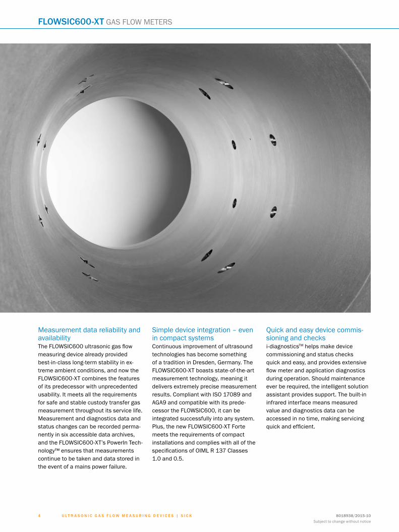
Measurement data reliability and availabilityThe FLOWSIC600 ultrasonic gas flow measuring device already provided best-in-class long-term stability in ex-treme ambient conditions, and now the FLOWSIC600-XT combines the features of its predecessor with unprecedented usability. It meets all the requirements for safe and stable custody transfer gas measurement throughout its service life. Measurement and diagnostics data and status changes can be recorded perma-nently in six accessible data archives, and the FLOWSIC600-XT’s PowerIn Tech-nology™ ensures that measurementscontinue to be taken and data stored in the event of a mains power failure.
Simple device integration – even in compact systemsContinuous improvement of ultrasound technologies has become something of a tradition in Dresden, Germany. The FLOWSIC600-XT boasts state-of-the-art measurement technology, meaning it delivers extremely precise measurement results. Compliant with ISO 17089 and AGA9 and compatible with its prede-cessor the FLOWSIC600, it can be integrated successfully into any system. Plus, the new FLOWSIC600-XT Forte meets the requirements of compact installations and complies with all of the specifications of OIML R 137 Classes 1.0 and 0.5.
Quick and easy device commis-sioning and checksi-diagnosticsTM helps make device commissioning and status checks quick and easy, and provides extensive flow meter and application diagnostics during operation. Should maintenance ever be required, the intelligent solution assistant provides support. The built-in infrared interface means measured value and diagnostics data can be accessed in no time, making servicing quick and efficient.
flowsic600-Xt GAS FLOW METERS
8018938/2015-10Subject to change without notice
5 U l t r a s o n i c g a s f l o w m e a s U r i n g d e v i c e s | s i c K
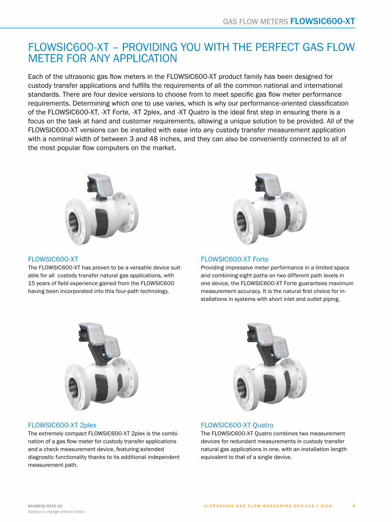
FLOWSIC600-XT – PROVIDING YOU WITH THE PERFECT GAS FLOW METER FOR ANY APPLICATIONEach of the ultrasonic gas flow meters in the FLOWSIC600-XT product family has been designed for custody transfer applications and fulfills the requirements of all the common national and international standards. There are four device versions to choose from to meet specific gas flow meter performance requirements. Determining which one to use varies, which is why our performance-oriented classification of the FLOWSIC600-XT, -XT Forte, -XT 2plex, and -XT Quatro is the ideal first step in ensuring there is a focus on the task at hand and customer requirements, allowing a unique solution to be provided. All of the FLOWSIC600-XT versions can be installed with ease into any custody transfer measurement application with a nominal width of between 3 and 48 inches, and they can also be conveniently connected to all of the most popular flow computers on the market.
FLOWSIC600-XTThe FLOWSIC600-XT has proven to be a versatile device suit-able for all custody transfer natural gas applications, with 15 years of field experience gained from the FLOWSIC600 having been incorporated into this four-path technology.
FLOWSIC600-XT ForteProviding impressive meter performance in a limited space and combining eight paths on two different path levels in one device, the FLOWSIC600-XT Forte guarantees maximum measurement accuracy. It is the natural first choice for in-stallations in systems with short inlet and outlet piping.
FLOWSIC600-XT 2plexThe extremely compact FLOWSIC600-XT 2plex is the combi-nation of a gas flow meter for custody transfer applications and a check measurement device, featuring extended diagnostic functionality thanks to its additional independent measurement path.
FLOWSIC600-XT QuatroThe FLOWSIC600-XT Quatro combines two measurement devices for redundant measurements in custody transfer natural gas applications in one, with an installation length equivalent to that of a single device.
GAS FLOW METERS flowsic600-Xt
8018938/2015-10Subject to change without notice
6 U l t r a s o n i c g a s f l o w m e a s U r i n g d e v i c e s | s i c K
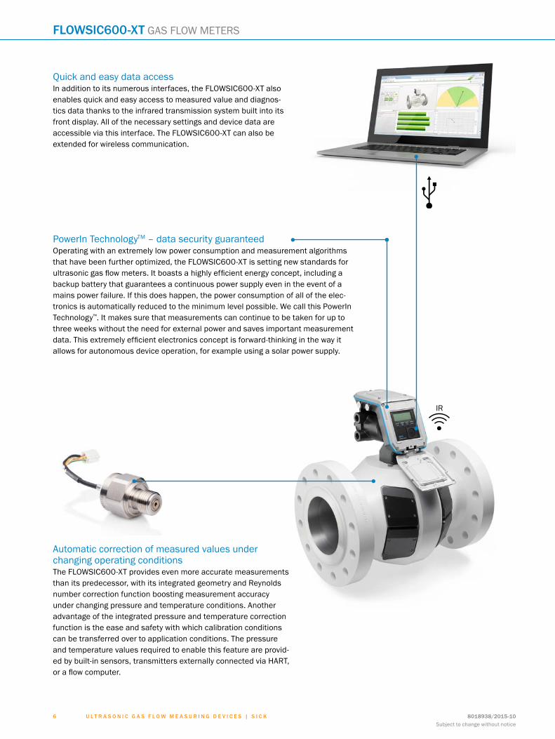
PowerIn TechnologyTM – data security guaranteedOperating with an extremely low power consumption and measurement algorithms that have been further optimized, the FLOWSIC600-XT is setting new standards for ultrasonic gas flow meters. It boasts a highly efficient energy concept, including a backup battery that guarantees a continuous power supply even in the event of a mains power failure. If this does happen, the power consumption of all of the elec-tronics is automatically reduced to the minimum level possible. We call this PowerIn Technology™. It makes sure that measurements can continue to be taken for up to three weeks without the need for external power and saves important measurement data. This extremely efficient electronics concept is forward-thinking in the way it allows for autonomous device operation, for example using a solar power supply.
Quick and easy data accessIn addition to its numerous interfaces, the FLOWSIC600-XT also enables quick and easy access to measured value and diagnos-tics data thanks to the infrared transmission system built into its front display. All of the necessary settings and device data are accessible via this interface. The FLOWSIC600-XT can also be extended for wireless communication.
IR
Automatic correction of measured values under changing operating conditionsThe FLOWSIC600-XT provides even more accurate measurements than its predecessor, with its integrated geometry and Reynolds number correction function boosting measurement accuracy under changing pressure and temperature conditions. Another advantage of the integrated pressure and temperature correction function is the ease and safety with which calibration conditions can be transferred over to application conditions. The pressure and temperature values required to enable this feature are provid-ed by built-in sensors, transmitters externally connected via HART, or a flow computer.
flowsic600-Xt GAS FLOW METERS
8018938/2015-10Subject to change without notice
7 U l t r a s o n i c g a s f l o w m e a s U r i n g d e v i c e s | s i c K
i-diagnostics™ – an essential tool for effective and efficient device and application diagnosticsi-diagnostics™ has so much more to offer than just diagnostics – it is an intelligent combination of firmware and software that means the device is safe, reliable, and easy to use for the entire operating time. i-diagnostics™ builds on the FLOWSIC600’s CBM (condition based maintenance) smart self-diagnosis functionality, providing useful information about the system status and any changes to it, in addition to device diagnostics. In order to assess the application, diagnostics data from cross-eyed beams is first factored in, with application faults, such as blocked flow conditioners, background noise, corrosion, and liquids in the gas, being detected immediately – making lengthy troubleshooting a thing of the past. Process data is constantly assessed on the basis of the integrated FingerPrint concept. This means that the measurement conditions during calibration can be compared with the measurement conditions during commissioning and with the current measurement and diagnostics data. An internal data logger continuously logs measured values for trend analyses to allow the historical measurement processes to be checked, as well as the results of the self-monitoring. A retroactive thorough check of the measurement process in the form of a graphic trend analy-sis is also possible.
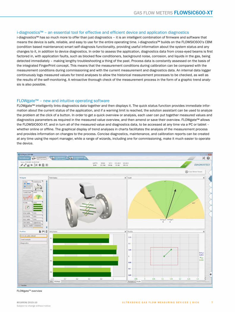
FLOWgateTM overview
FLOWgate™ – new and intuitive operating softwareFLOWgate™ intelligently links diagnostics data together and then displays it. The quick status function provides immediate infor-mation about the current status of the application, and if a warning limit is reached, the solution assistant can be used to analyze the problem at the click of a button. In order to get a quick overview or analysis, each user can put together measured values and diagnostics parameters as required in the measured value overview, and then amend or save their overview. FLOWgate™ allows the FLOWSIC600-XT, and in turn all of the measured value and diagnostics data, to be accessed at any time via a PC or tablet – whether online or offline. The graphical display of trend analyses in charts facilitates the analysis of the measurement process and provides information on changes to the process. Concise diagnostics, maintenance, and calibration reports can be created at any time using the report manager, while a range of wizards, including one for commissioning, make it much easier to operate the device.
GAS FLOW METERS flowsic600-Xt
U l t r a s o n i c g a s f l o w m e a s U r i n g d e v i c e s | s i c K 8018938/2015-10Subject to change without notice
8
flowsic600-Xt GAS FLOW METERS
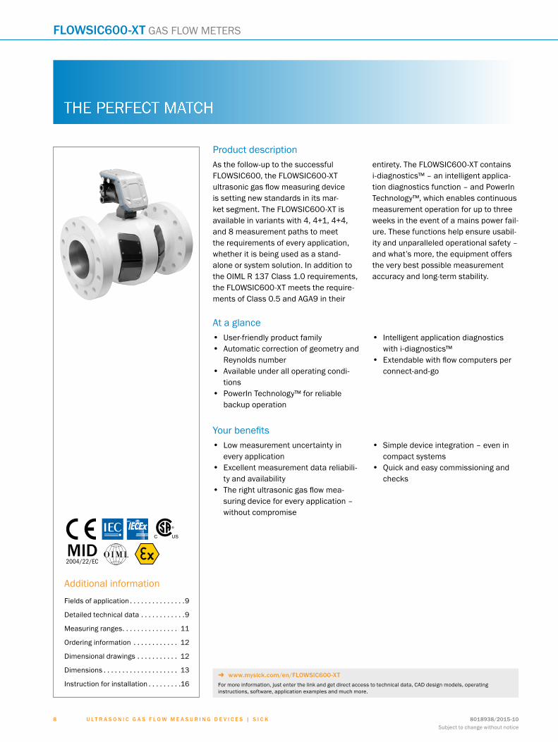
Product descriptionAs the follow-up to the successful FLOWSIC600, the FLOWSIC600-XT ultrasonic gas flow measuring device is setting new standards in its mar-ket segment. The FLOWSIC600-XT is available in variants with 4, 4+1, 4+4, and 8 measurement paths to meet the requirements of every application, whether it is being used as a stand-alone or system solution. In addition to the OIML R 137 Class 1.0 requirements, the FLOWSIC600-XT meets the require-ments of Class 0.5 and AGA9 in their
entirety. The FLOWSIC600-XT contains i-diagnostics™ – an intelligent applica-tion diagnostics function – and PowerIn Technology™, which enables continuous measurement operation for up to three weeks in the event of a mains power fail-ure. These functions help ensure usabil-ity and unparalleled operational safety – and what’s more, the equipment offers the very best possible measurement accuracy and long-term stability.
At a glance• User-friendly product family• Automatic correction of geometry and
Reynolds number• Available under all operating condi-
tions• PowerIn Technology™ for reliable
backup operation
• Intelligent application diagnostics with i-diagnostics™
• Extendable with flow computers per connect-and-go
Your benefits• Low measurement uncertainty in
every application• Excellent measurement data reliabili-
ty and availability• The right ultrasonic gas flow mea-
suring device for every application – without compromise
• Simple device integration – even in compact systems
• Quick and easy commissioning and checks
Ultrasonic gas flow measuring devicesGAS FLOW METERSflowsic600-Xt
Subject to change without notice
.
THE PERFECT MATCH
Additional information
Fields of application . . . . . . . . . . . . . . .9
Detailed technical data . . . . . . . . . . . .9
Measuring ranges. . . . . . . . . . . . . . . 11
Ordering information . . . . . . . . . . . . 12
Dimensional drawings . . . . . . . . . . . 12
Dimensions . . . . . . . . . . . . . . . . . . . . 13
Instruction for installation . . . . . . . . .16
C US
®
- www.mysick.com/en/FLOWSIC600-XTFor more information, just enter the link and get direct access to technical data, CAD design models, operating instructions, software, application examples and much more.
ABCDEF
HIJKLMNOPQRST
U l t r a s o n i c g a s f l o w m e a s U r i n g d e v i c e s | s i c K8018938/2015-10Subject to change without notice
99
GAS FLOW METERS flowsic600-Xt
Fields of application• Custody transfer measurement of natural gas• Transport and storage of gas
• Onshore and offshore applications• Gas production applications with H2S and CO2 content
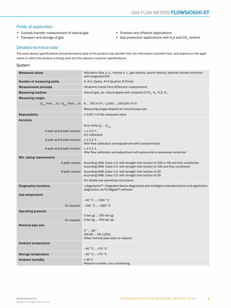
Detailed technical dataThe exact device specifications and performance data of the product may deviate from the information provided here, and depend on the appli-cation in which the product is being used and the relevant customer specifications.
System
Measured values Volumetric flow, a. c., volume a. c., gas velocity, sound velocity, optional volume correction with integrated EVC
Number of measuring paths 4, 4+1 (2plex), 4+4 (Quatro), 8 (Forte)
Measurement principle Ultrasonic transit time difference measurement
Measuring medium Natural gas, air, natural gases with contents of CO2, N2, H2S, O2
Measuring ranges
Qmin from ... to / Qmax from ... to 8 ... 750 m³/h / 1,000 ... 100,000 m³/h
Measuring ranges depend on nominal pipe size
Repeatability ± 0.05 % of the measured value
Accuracy
Error limits Qt ... Qmax
4-path and 8-path version: ≤ ± 0.5 % Dry calibrated
4-path and 8-path version: ≤ ± 0.2 % After flow calibration and adjustment with constant factor
4-path and 8-path version: ≤ ± 0.1 % After flow calibration and adjustment with polynomial or piecewise correction
Min. piping requirements
4-path version According OIML Class 1.0: with straight inlet section of 10D or 5D with flow conditioner According OIML Class 0.5: with straight inlet section of 10D and flow conditioner
8-path version According OIML Class 1.0: with straight inlet section of 2D According OIML Class 0.5: with straight inlet section of 5D
For details see operating instructions
Diagnostics functions i-diagnostics™: integrated device diagnostics and intelligent extended device and application diagnostics via FLOWgate™ software
Gas temperature
–40 °C ... +180 °C
On request: –194 °C ... +280 °C
Operating pressure
On request:0 bar (g) ... 250 bar (g)0 bar (g) ... 450 bar (g)
Nominal pipe size
3 ″ ... 48 ″ (DN 80 ... DN 1200), Other nominal pipe sizes on request
Ambient temperature
–40 °C ... +70 °C
Storage temperature –40 °C ... +70 °C
Ambient humidity ≤ 95 % Relative humidity; non-condensing
ABCDEF
HIJKLMNOPQRST
U l t r a s o n i c g a s f l o w m e a s U r i n g d e v i c e s | s i c K 8018938/2015-10Subject to change without notice
1 0
flowsic600-Xt GAS FLOW METERS
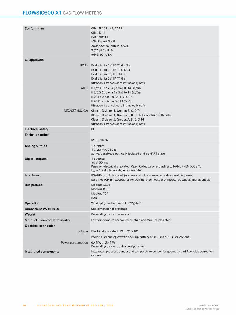
Conformities OIML R 137 1+2, 2012OIML D 11ISO 17089-1AGA-Report No. 92004/22/EC (MID MI-002)97/23/EC (PED)94/9/EC (ATEX)
Ex-approvals
IECEx Ex d e ia [ia Ga] IIC T4 Gb/GaEx d e ia [ia Ga] IIA T4 Gb/GaEx d e ia [ia Ga] IIC T4 GbEx d e ia [ia Ga] IIA T4 GbUltrasonic transducers intrinsically safe
ATEX II 1/2G Ex d e ia [ia Ga] IIC T4 Gb/GaII 1/2G Ex d e ia [ia Ga] IIA T4 Gb/GaII 2G Ex d e ia [ia Ga] IIC T4 GbII 2G Ex d e ia [ia Ga] IIA T4 GbUltrasonic transducers intrinsically safe
NEC/CEC (US/CA) Class I, Division 1, Groups B, C, D T4Class I, Division 1, Groups B, C, D T4, Exia intrinsically safeClass I, Division 2, Groups A, B, C, D T4Ultrasonic transducers intrinsically safe
Electrical safety CE
Enclosure rating
IP 66 / IP 67
Analog outputs 1 output: 4 ... 20 mA, 250 Ω Active/passive, electrically isolated and as HART slave
Digital outputs 4 outputs: 30 V, 50 mA Passive, electrically isolated, Open Collector or according to NAMUR (EN 50227), fmax = 10 kHz (scalable) or as encoder
Interfaces RS-485 (3x, 2x for configuration, output of measured values and diagnosis)Ethernet TCP/IP (1x optional for configuration, output of measured values and diagnosis)
Bus protocol Modbus ASCIIModbus RTUModbus TCPHART
Operation Via display and software FLOWgate™
Dimensions (W x H x D) See dimensional drawings
Weight Depending on device version
Material in contact with media Low temperature carbon steel, stainless steel, duplex steel
Electrical connection
Voltage Electrically isolated: 12 ... 24 V DC
PowerIn Technology™ with back-up battery (2,400 mAh, 10.8 V), optional
Power consumption 0.45 W ... 2.45 W Depending on electronics configuration
Integrated components Integrated pressure sensor and temperature sensor for geometry and Reynolds correction (option)
ABCDEF
HIJKLMNOPQRST
U l t r a s o n i c g a s f l o w m e a s U r i n g d e v i c e s | s i c K8018938/2015-10Subject to change without notice
1 11 1
GAS FLOW METERS flowsic600-Xt
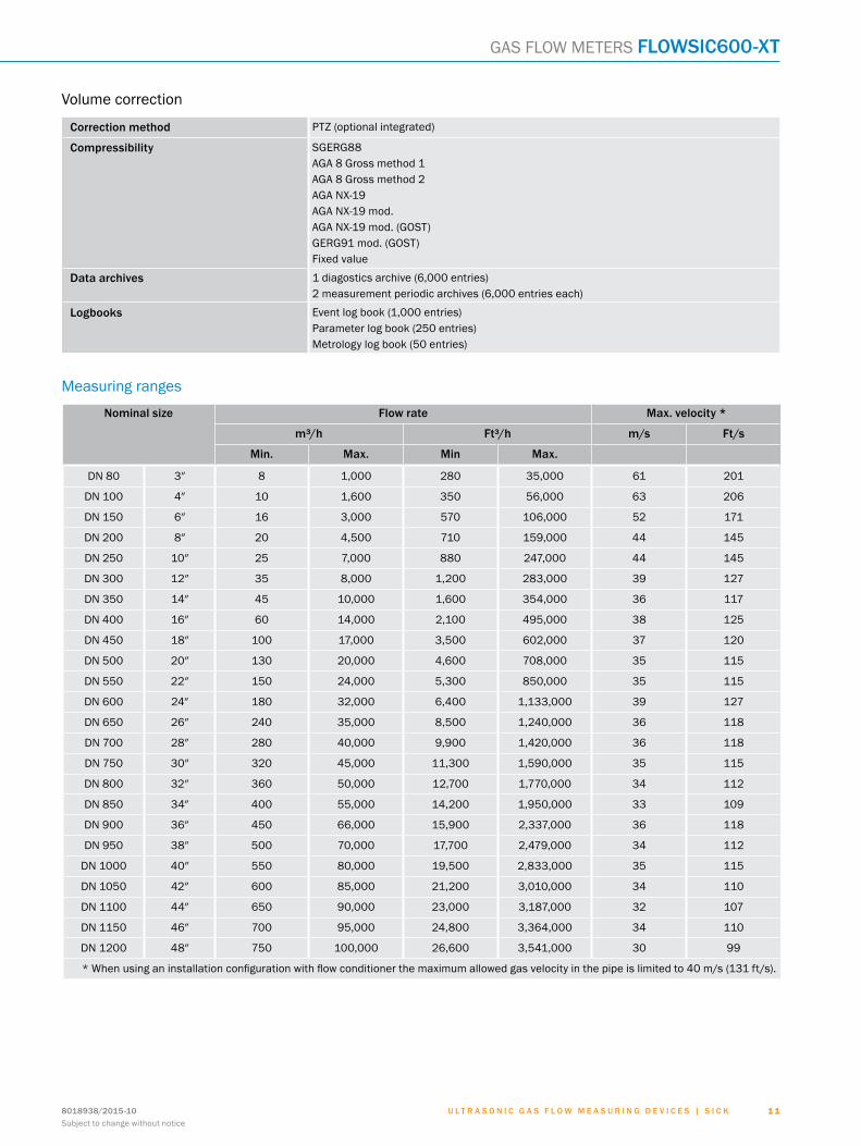
Volume correction
Correction method PTZ (optional integrated)
Compressibility SGERG88AGA 8 Gross method 1AGA 8 Gross method 2AGA NX-19AGA NX-19 mod.AGA NX-19 mod. (GOST)GERG91 mod. (GOST)Fixed value
Data archives 1 diagostics archive (6,000 entries)2 measurement periodic archives (6,000 entries each)
Logbooks Event log book (1,000 entries)Parameter log book (250 entries)Metrology log book (50 entries)
Measuring ranges
Nominal size Flow rate Max. velocity *
m³/h Ft³/h m/s Ft/s
Min. Max. Min Max.
DN 80 3″ 8 1,000 280 35,000 61 201
DN 100 4″ 10 1,600 350 56,000 63 206
DN 150 6″ 16 3,000 570 106,000 52 171
DN 200 8″ 20 4,500 710 159,000 44 145
DN 250 10″ 25 7,000 880 247,000 44 145
DN 300 12″ 35 8,000 1,200 283,000 39 127
DN 350 14″ 45 10,000 1,600 354,000 36 117
DN 400 16″ 60 14,000 2,100 495,000 38 125
DN 450 18″ 100 17,000 3,500 602,000 37 120
DN 500 20″ 130 20,000 4,600 708,000 35 115
DN 550 22″ 150 24,000 5,300 850,000 35 115
DN 600 24″ 180 32,000 6,400 1,133,000 39 127
DN 650 26″ 240 35,000 8,500 1,240,000 36 118
DN 700 28″ 280 40,000 9,900 1,420,000 36 118
DN 750 30″ 320 45,000 11,300 1,590,000 35 115
DN 800 32″ 360 50,000 12,700 1,770,000 34 112
DN 850 34″ 400 55,000 14,200 1,950,000 33 109
DN 900 36″ 450 66,000 15,900 2,337,000 36 118
DN 950 38″ 500 70,000 17,700 2,479,000 34 112
DN 1000 40″ 550 80,000 19,500 2,833,000 35 115
DN 1050 42″ 600 85,000 21,200 3,010,000 34 110
DN 1100 44″ 650 90,000 23,000 3,187,000 32 107
DN 1150 46″ 700 95,000 24,800 3,364,000 34 110
DN 1200 48″ 750 100,000 26,600 3,541,000 30 99
* When using an installation configuration with flow conditioner the maximum allowed gas velocity in the pipe is limited to 40 m/s (131 ft/s).
ABCDEF
HIJKLMNOPQRST
U l t r a s o n i c g a s f l o w m e a s U r i n g d e v i c e s | s i c K 8018938/2015-10Subject to change without notice
1 2
flowsic600-Xt GAS FLOW METERS
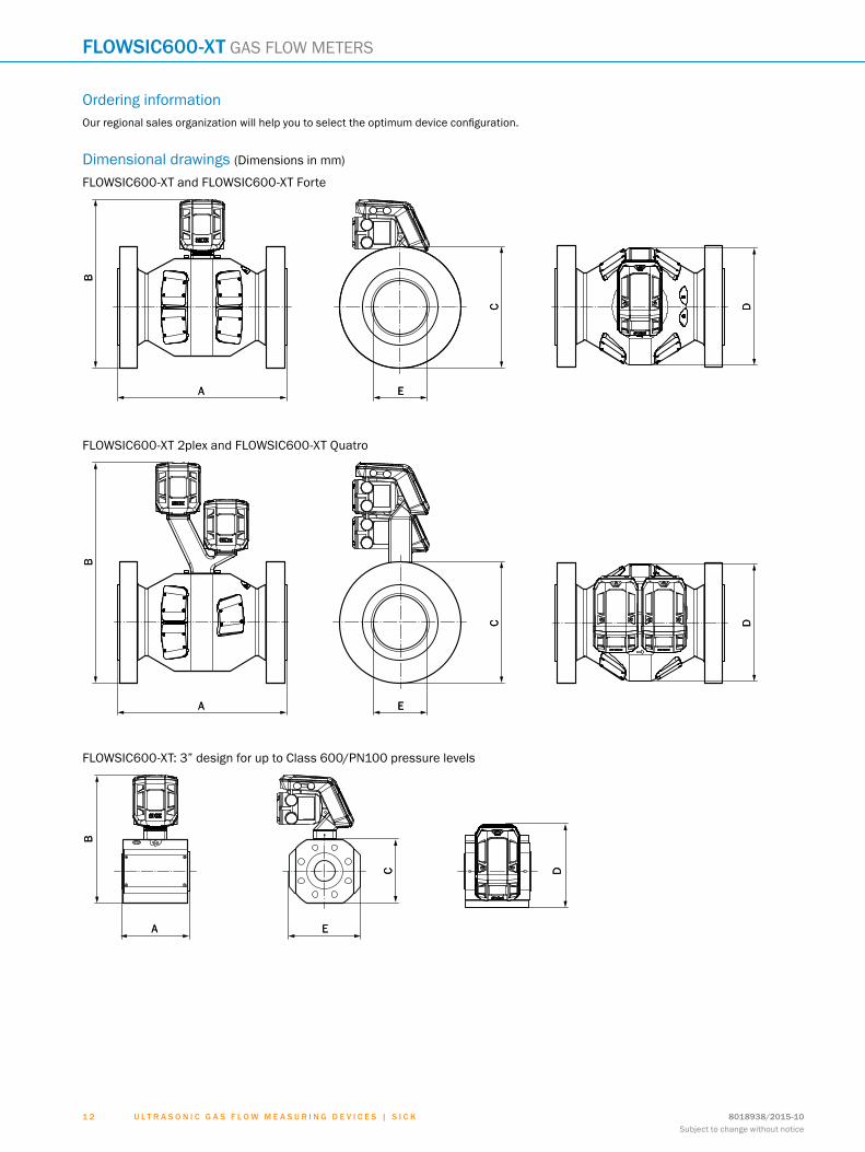
Ordering informationOur regional sales organization will help you to select the optimum device configuration.
Dimensional drawings (Dimensions in mm)
FLOWSIC600-XT and FLOWSIC600-XT Forte
A
B
C D
EA
B
C D
E
FLOWSIC600-XT 2plex and FLOWSIC600-XT Quatro
A
B
C D
EA
B
C D
E
FLOWSIC600-XT: 3” design for up to Class 600/PN100 pressure levels
A
B
C D
EA
B
C D
E
ABCDEF
HIJKLMNOPQRST
U l t r a s o n i c g a s f l o w m e a s U r i n g d e v i c e s | s i c K8018938/2015-10Subject to change without notice
1 31 3
GAS FLOW METERS flowsic600-Xt
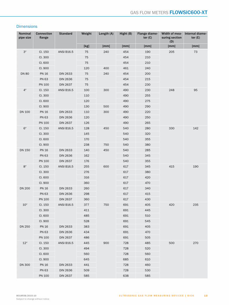
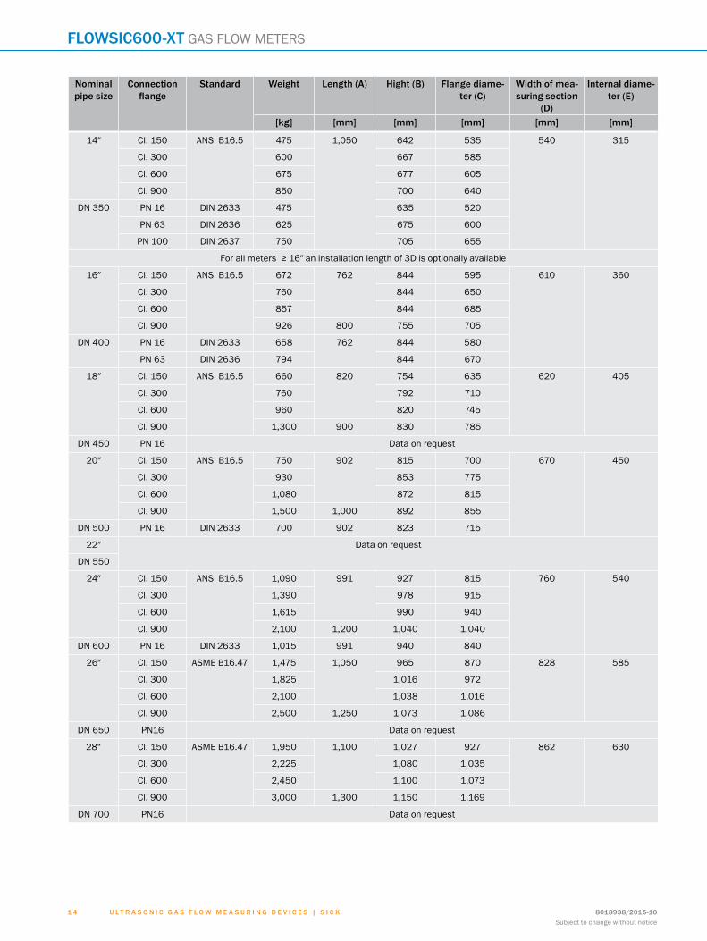
Dimensions
Nominal pipe size
Connection flange
Standard Weight Length (A) Hight (B) Flange diame-ter (C)
Width of mea-suring section
(D)
Internal diame-ter (E)
[kg] [mm] [mm] [mm] [mm] [mm]
3″ Cl. 150 ANSI B16.5 75 240 454 190 205 73
Cl. 300 75 454 210
Cl. 600 75 454 210
Cl. 900 120 400 461 240
DN 80 PN 16 DIN 2633 75 240 454 200
PN 63 DIN 2636 75 454 215
PN 100 DIN 2637 75 454 230
4″ Cl. 150 ANSI B16.5 100 300 490 230 248 95
Cl. 300 110 490 255
Cl. 600 120 490 275
Cl. 900 130 500 490 290
DN 100 PN 16 DIN 2633 110 300 490 220
PN 63 DIN 2636 120 490 250
PN 100 DIN 2637 126 490 265
6″ Cl. 150 ANSI B16.5 128 450 540 280 330 142
Cl. 300 145 540 320
Cl. 600 170 540 355
Cl. 900 238 750 540 380
DN 150 PN 16 DIN 2633 140 450 540 285
PN 63 DIN 2636 162 540 345
PN 100 DIN 2637 176 540 355
8″ Cl. 150 ANSI B16.5 255 600 617 345 415 190
Cl. 300 276 617 380
Cl. 600 316 617 420
Cl. 900 360 617 470
DN 200 PN 16 DIN 2633 260 617 340
PN 63 DIN 2636 298 617 415
PN 100 DIN 2637 360 617 430
10″ Cl. 150 ANSI B16.5 377 750 691 405 420 235
Cl. 300 411 691 445
Cl. 600 485 691 510
Cl. 900 528 691 545
DN 250 PN 16 DIN 2633 383 691 405
PN 63 DIN 2636 434 691 470
PN 100 DIN 2637 486 691 505
12″ Cl. 150 ANSI B16.5 445 900 728 485 500 270
Cl. 300 494 728 520
Cl. 600 560 728 560
Cl. 900 645 685 610
DN 300 PN 16 DIN 2633 441 728 460
PN 63 DIN 2636 509 728 530
PN 100 DIN 2637 585 638 585
ABCDEF
HIJKLMNOPQRST
U l t r a s o n i c g a s f l o w m e a s U r i n g d e v i c e s | s i c K 8018938/2015-10Subject to change without notice
1 4
flowsic600-Xt GAS FLOW METERS
Nominal pipe size
Connection flange
Standard Weight Length (A) Hight (B) Flange diame-ter (C)
Width of mea-suring section
(D)
Internal diame-ter (E)
[kg] [mm] [mm] [mm] [mm] [mm]
14″ Cl. 150 ANSI B16.5 475 1,050 642 535 540 315
Cl. 300 600 667 585
Cl. 600 675 677 605
Cl. 900 850 700 640
DN 350 PN 16 DIN 2633 475 635 520
PN 63 DIN 2636 625 675 600
PN 100 DIN 2637 750 705 655
For all meters ≥ 16″ an installation length of 3D is optionally available
16″ Cl. 150 ANSI B16.5 672 762 844 595 610 360
Cl. 300 760 844 650
Cl. 600 857 844 685
Cl. 900 926 800 755 705
DN 400 PN 16 DIN 2633 658 762 844 580
PN 63 DIN 2636 794 844 670
18″ Cl. 150 ANSI B16.5 660 820 754 635 620 405
Cl. 300 760 792 710
Cl. 600 960 820 745
Cl. 900 1,300 900 830 785
DN 450 PN 16 Data on request
20″ Cl. 150 ANSI B16.5 750 902 815 700 670 450
Cl. 300 930 853 775
Cl. 600 1,080 872 815
Cl. 900 1,500 1,000 892 855
DN 500 PN 16 DIN 2633 700 902 823 715
22″ Data on request
DN 550
24″ Cl. 150 ANSI B16.5 1,090 991 927 815 760 540
Cl. 300 1,390 978 915
Cl. 600 1,615 990 940
Cl. 900 2,100 1,200 1,040 1,040
DN 600 PN 16 DIN 2633 1,015 991 940 840
26″ Cl. 150 ASME B16.47 1,475 1,050 965 870 828 585
Cl. 300 1,825 1,016 972
Cl. 600 2,100 1,038 1,016
Cl. 900 2,500 1,250 1,073 1,086
DN 650 PN16 Data on request
28“ Cl. 150 ASME B16.47 1,950 1,100 1,027 927 862 630
Cl. 300 2,225 1,080 1,035
Cl. 600 2,450 1,100 1,073
Cl. 900 3,000 1,300 1,150 1,169
DN 700 PN16 Data on request
ABCDEF
HIJKLMNOPQRST
U l t r a s o n i c g a s f l o w m e a s U r i n g d e v i c e s | s i c K8018938/2015-10Subject to change without notice
1 51 5
GAS FLOW METERS flowsic600-Xt
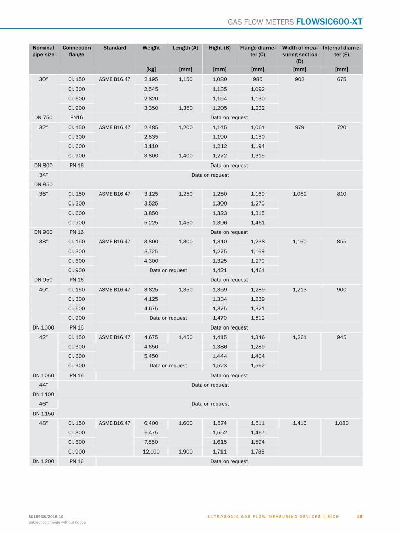
Nominal pipe size
Connection flange
Standard Weight Length (A) Hight (B) Flange diame-ter (C)
Width of mea-suring section
(D)
Internal diame-ter (E)
[kg] [mm] [mm] [mm] [mm] [mm]
30″ Cl. 150 ASME B16.47 2,195 1,150 1,080 985 902 675
Cl. 300 2,545 1,135 1,092
Cl. 600 2,820 1,154 1,130
Cl. 900 3,350 1,350 1,205 1,232
DN 750 PN16 Data on request
32″ Cl. 150 ASME B16.47 2,485 1,200 1,145 1,061 979 720
Cl. 300 2,835 1,190 1,150
Cl. 600 3,110 1,212 1,194
Cl. 900 3,800 1,400 1,272 1,315
DN 800 PN 16 Data on request
34″ Data on request
DN 850
36″ Cl. 150 ASME B16.47 3,125 1,250 1,250 1,169 1,082 810
Cl. 300 3,525 1,300 1,270
Cl. 600 3,850 1,323 1,315
Cl. 900 5,225 1,450 1,396 1,461
DN 900 PN 16 Data on request
38″ Cl. 150 ASME B16.47 3,800 1,300 1,310 1,238 1,160 855
Cl. 300 3,725 1,275 1,169
Cl. 600 4,300 1,325 1,270
Cl. 900 Data on request 1,421 1,461
DN 950 PN 16 Data on request
40″ Cl. 150 ASME B16.47 3,825 1,350 1,359 1,289 1,213 900
Cl. 300 4,125 1,334 1,239
Cl. 600 4,675 1,375 1,321
Cl. 900 Data on request 1,470 1,512
DN 1000 PN 16 Data on request
42″ Cl. 150 ASME B16.47 4,675 1,450 1,415 1,346 1,261 945
Cl. 300 4,650 1,386 1,289
Cl. 600 5,450 1,444 1,404
Cl. 900 Data on request 1,523 1,562
DN 1050 PN 16 Data on request
44″ Data on request
DN 1100
46″ Data on request
DN 1150
48″ Cl. 150 ASME B16.47 6,400 1,600 1,574 1,511 1,416 1,080
Cl. 300 6,475 1,552 1,467
Cl. 600 7,850 1,615 1,594
Cl. 900 12,100 1,900 1,711 1,785
DN 1200 PN 16 Data on request
ABCDEF
HIJKLMNOPQRST
U l t r a s o n i c g a s f l o w m e a s U r i n g d e v i c e s | s i c K 8018938/2015-10Subject to change without notice
1 6
flowsic600-Xt GAS FLOW METERS
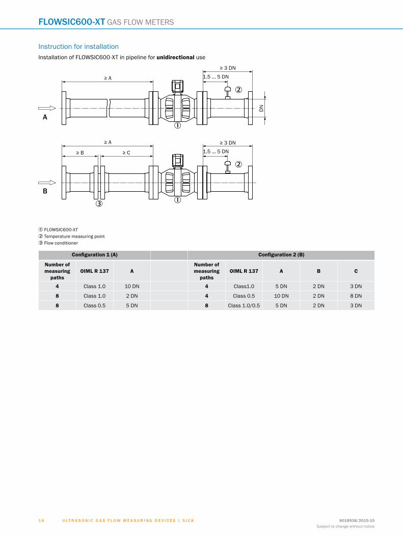
Instruction for installationInstallation of FLOWSIC600-XT in pipeline for unidirectional use
≥ A 1.5 ... 5 DN
DN
≥ A
≥ 3 DN
≥ 3 DN
1.5 ... 5 DN≥ C≥ B
�
�
�
�
�
A
B
1 FLOWSIC600-XT2 Temperature measuring point3 Flow conditioner
Configuration 1 (A) Configuration 2 (B)
Number of measuring
pathsOIML R 137 A
Number of measuring
pathsOIML R 137 A B C
4 Class 1.0 10 DN 4 Class1.0 5 DN 2 DN 3 DN
8 Class 1.0 2 DN 4 Class 0.5 10 DN 2 DN 8 DN
8 Class 0.5 5 DN 8 Class 1.0/0.5 5 DN 2 DN 3 DN
ABCDEF
HIJKLMNOPQRST
U l t r a s o n i c g a s f l o w m e a s U r i n g d e v i c e s | s i c K8018938/2015-10Subject to change without notice
1 71 7
GAS FLOW METERS flowsic600-Xt
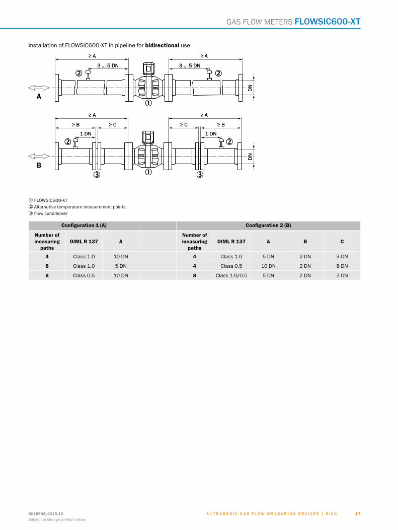
Installation of FLOWSIC600-XT in pipeline for bidirectional use
�
�
� �
��
� �
≥ A≥ A
3 ... 5 DN 3 ... 5 DN
DN
1 DN 1 DN
≥ A ≥ A
≥ B≥ C≥ B ≥ C
DN
A
B
�
�
� �
��
� �
≥ A≥ A
3 ... 5 DN 3 ... 5 DN
DN
1 DN 1 DN
≥ A ≥ A
≥ B≥ C≥ B ≥ C
DN
A
B
1 FLOWSIC600-XT2 Alternative temperature measurement points3 Flow conditioner
Configuration 1 (A) Configuration 2 (B)
Number of measuring
pathsOIML R 137 A
Number of measuring
pathsOIML R 137 A B C
4 Class 1.0 10 DN 4 Class 1.0 5 DN 2 DN 3 DN
8 Class 1.0 5 DN 4 Class 0.5 10 DN 2 DN 8 DN
8 Class 0.5 10 DN 8 Class 1.0/0.5 5 DN 2 DN 3 DN
ABCDEF
HIJKLMNOPQRST

8018938/2015-10Subject to change without notice
1 8 U l t r a s o n i c g a s f l o w m e a s U r i n g d e v i c e s | s i c K
NOTES

SERVICES FOR MACHINES AND SYSTEMS: SICK LifeTime ServicesOur comprehensive and versatile LifeTime Services are the perfect addition to the comprehensive range of products from SICK. The services range from product-independent consulting to traditional product services.
Training and educationPractical, focused and professional
Upgrade and retrofitsEasy, safe and economical
Consulting and designSafe and professional
Verification and optimizationSafe and regularly inspected
Product and system supportReliable, fast and on-site
REGISTER AT WWW.SICK.COM TODAY AND ENJOY ALL THE BENEFITS
Select products, accessories, documentation and soft-ware quickly and easily.
Create, save and share personalized wish lists.
View the net price and date of delivery for every product.
Requests for quotation, ordering and delivery tracking made easy.
Overview of all quotations and orders.
Direct ordering: submit even very complex orders in moments.
View the status of quotations and orders at any time. Receive e-mail notifications of status changes.
Easily repeat previous orders.
Conveniently export quotations and orders to work with your systems.
m
m
m
m
m
m
m
m
m
SERVICES
8018938/2015-10Subject to change without notice
1 9 U l t r a s o n i c g a s f l o w m e a s U r i n g d e v i c e s | s i c K

SICK AG | Waldkirch | Germany | www.sick.com
SICK AT A GLANCESICK is a leading manufacturer of intelligent sensors and sensor solutions for industrial applications. With almost 7,000 employees and over 50 subsidiaries and equity investments as well as numerous represen-tative offices worldwide, we are always close to our customers. A unique range of products and services creates the perfect basis for controlling processes securely and efficiently, protecting individuals from accidents and preventing damage to the environment.
We have extensive experience in various industries and understand their processes and requirements. With intelligent sensors, we can deliver exactly what our customers need. In application centers in Europe, Asia and North America, system solutions are tested and optimized in accordance with customer specifica-tions. All this makes us a reliable supplier and development partner.
Comprehensive services round out our offering: SICK LifeTime Services provide support throughout the machine life cycle and ensure safety and productivity.
For us, that is “Sensor Intelligence.”
Worldwide presence:
Australia, Austria, Belgium, Brazil, Canada, Chile, China, Czech Republic, Denmark, Finland, France, Germany, Great Britain, Hungary, India, Israel, Italy, Japan, Malaysia, Mexico, Netherlands, New Zealand, Norway, Poland, Romania, Russia, Singapore, Slovakia, Slovenia, South Africa, South Korea, Spain, Sweden, Switzerland, Taiwan, Thailand, Turkey, United Arab Emirates, USA, Vietnam.
Detailed addresses and additional representatives - www.sick.com
8018
938/
2015
-10
∙ Pre
USm
od e
n44


