40
Flowtite Pipe Systems Gravity Sewer
Flowtite Pipe SystemsGravity Sewer
2
1 Production Process 3
2 Product Advantages 4Features & Benefits .................................................................................................................... 4
3 Certificates and Approvals 4
4 Quality Characteristics 5 4.1 Raw Materials ...................................................................................................................... 5 4.2 Physical Properties .............................................................................................................. 5 4.3 Finished Pipe Properties ....................................................................................................... 5 4.4 Other Quality Characteristics ................................................................................................ 5
5 Product Range 6 5.1 Stiffness Classes ................................................................................................................. 6 5.2 Pressure ............................................................................................................................... 6 5.3 Length .................................................................................................................................. 6 5.4 Standard Pipe and Coupling Data Sheet ............................................................................ 6
6 Pipe Joining 8Double Bell Coupling (FSC) ....................................................................................................... 8
7 Accessories 9 7.1 Segmented Bends ............................................................................................................. 10 7.2 Segmented Reducers – Concentric & Eccentic – ............................................................. 12 7.3 Segmented Tees – Equal & Reduced – ............................................................................. 14
7.4 Segmented Branches 45° – Equal & Reduced – .............................................................. 18 7.5 Moulded Bends ................................................................................................................. 20
7.6 Moulded Reducers – Concentric & Eccentric – ................................................................ 217.7 Moulded Tees – Equal and Reduced – .............................................................................. 227.8 Moulded Branches 45° – Equal & Reduced – .................................................................. 23
7.9 Saddle Pieces – Screwed & Glued – ................................................................................ 25 7.10 Saddle Pieces 90° – Screwed & Glued – ........................................................................ 26
7.11 Saddle Pieces 45° – Screwed & Glued – ........................................................................ 28 7.12 Installation of Saddle Pieces ........................................................................................... 30 7.13 Wall Couplings ................................................................................................................. 32 7.14 End-Caps ......................................................................................................................... 33
7.15 Socket Plugs .................................................................................................................... 337.16 Adapter Coupling GRP-PVC Plain Ends ......................................................................... 347.17 Adapter Coupling GRP-Clay Plain Ends ......................................................................... 347.18 Segmented Inspection Pieces ......................................................................................... 357.19 Wall Connection Piece Type E ......................................................................................... 367.20 Wall Connection Piece Type F ......................................................................................... 367.21 Wall Connection Piece Type G ........................................................................................ 377.22 Short Section Pipe ........................................................................................................... 387.23 Manholes ......................................................................................................................... 38
8 Local Approvals and Certificates 39
02
03
04
05
06
07
01
08
3
02
03
04
05
06
07
08
09
1 Production Process
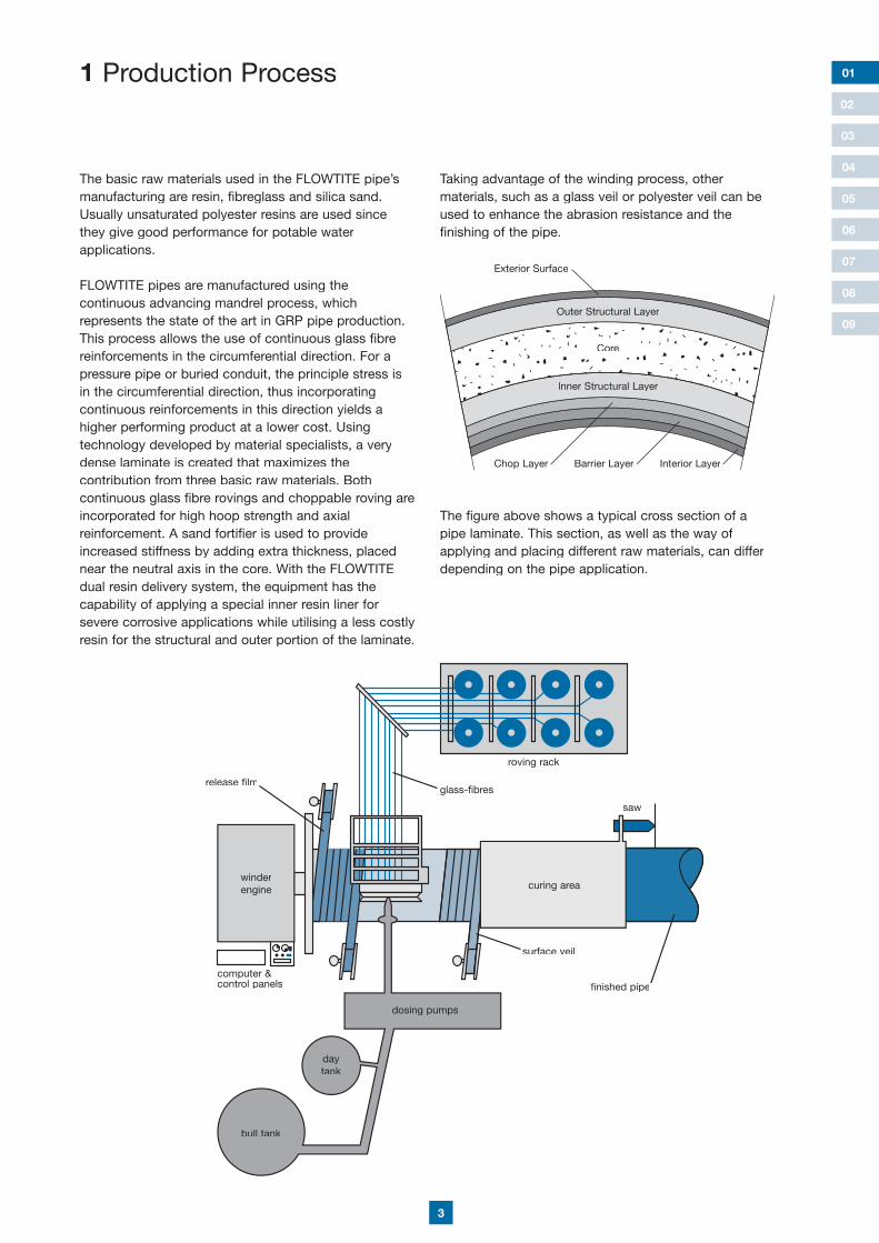
The basic raw materials used in the FLOWTITE pipe’s manufacturing are resin, fibreglass and silica sand. Usually unsaturated polyester resins are used since they give good performance for potable water applications.
FLOWTITE pipes are manufactured using the continuous advancing mandrel process, which represents the state of the art in GRP pipe production. This process allows the use of continuous glass fibre reinforcements in the circumferential direction. For a pressure pipe or buried conduit, the principle stress is in the circumferential direction, thus incorporating continuous reinforcements in this direction yields a higher performing product at a lower cost. Using technology developed by material specialists, a very dense laminate is created that maximizes the contribution from three basic raw materials. Both continuous glass fibre rovings and choppable roving are incorporated for high hoop strength and axial reinforcement. A sand fortifier is used to provide increased stiffness by adding extra thickness, placed near the neutral axis in the core. With the FLOWTITEdual resin delivery system, the equipment has the capability of applying a special inner resin liner for severe corrosive applications while utilising a less costly resin for the structural and outer portion of the laminate.
01
Taking advantage of the winding process, other materials, such as a glass veil or polyester veil can be used to enhance the abrasion resistance and the finishing of the pipe.
The figure above shows a typical cross section of a pipe laminate. This section, as well as the way of applying and placing different raw materials, can differ depending on the pipe application.
curing area
roving rack
glass-fibres
saw
bull tank
daytank
dosing pumps
finished pipe
surface veil
winderengine
release film
computer &control panels
Exterior Surface
Outer Structural Layer
Inner Structural Layer
Core
Chop Layer Interior LayerBarrier Layer

4
01
04
05
06
07
08
09
02
2 Product Advantages
FLOWTITE Technology has been able to bring a productto the market that can provide a low cost, long-term piping solution to customers around the world. The long list of features and benefits add up to provide the optimum installed and life cycle cost system.
Features & Benefits
Corrosion-resistant• Long, effective service-life materials• No need for linings, coatings, cathodic protection, wraps or other forms of corrosion protection• Low maintenance costs• Hydraulic characteristics essentially constant over time
Light weight(1/4 weight of ductile iron; 1/10 weight of concrete and clay)• Low transport costs (nestable)• Eliminates need for expensive pipe handling equipment
Short and long standard lengths(up to 18 metres with individual lengths on request)• Fewer joints reduce installation time• More pipe per transport vehicle means lower delivery costs
Extremely smooth bore• Low friction loss means lower operating costs• Minimum slime build-up can help lower cleaning costs
Precision FLOWTITEwith elastomeric gaskets• Tight, efficient joints designed for coupling to eliminate infiltration and ex-filtration• Ease of joining, reducing installation time• Accommodates small changes in line direction without fittings or differential settlement
Flexible manufacturing• Custom diameters can be process manufactured to provide maximum flow volumes with ease of installation for rehabilitation lining projects
High technology pipe design• Lower wave celerity than other piping materials can mean less cost when designing for surge and water hammer pressures
High technology pipe manufacturing system• High and consistent product quality worldwide which produces pipe ensures a reliable product that complies to stringent performance standards (AWWA, ASTM, DIN, EN, etc.)
• Quick and easy installation with construction site equipment due to light weight• Fast installation with a reduced number of couplings due to pipe lengths up to 18 m• simple and inexpensive tightness tests• long usage with consistently high flow rates• minimal effort for repairs and maintenance• excellent corrosion resistance• reinforced inner surface with a high resistance against abrasion
Due to these factors, projects made with FLOWTITEpipe systems are very economical and long-lasting with low maintenance efforts over the years.
3 Certificates and ApprovalsFLOWTITE pipe systems have been tested and approved for the conveyance of gravity sewer lines meeting many of the world’s leading authorities’ and testing institutes’ criteria, including:• SABS South African bureau of standards• Kitemark – UK• Bureau of Indian standards• AENOR Asciacionpanole de normalizacion y certificacion – Spain• COBRTI INSTAL – Poland• IRAM – Instituto de Racionalización de Materiales – Argentina• Kiwa – Komo product certificate K22463/03 – The Netherlands• BCCA Belgian Construction Certification Association BENOR BB 652-665 – Belgium• ON Österreichisches Normungsinstitut ON-N 2005 085 - AustriaI• GH CERTIFIKAT SUKLADNOSTIBR. 23-070/06 – Croatia• Institut pro Testování a certtifikaci, A.S.01 0187 V/AO/a – Czech Republic• CERTIFIKAT KONTROLE PROIZVODIJEIgmat d.d. VOL2P-CPD-0067 – Slovenia• CSTB Centre Scientifique et Technique du Bâtiment CSTBat-1/01-AS-136 FLOWTITE G – France• Centralny Osrodek Badawczo - Rozwojowy Techniki InstalacyjnejAT/2002-02-1285-03 – Poland• Deutsches Institut für Bautechnik (DIBt) Z-42.1-317 – Germany
FLOWTITE pipe systems fulfil the product standards AWWA, ASTM, DIN, ISO and EN. Other local approvals are also available, dependent on country specific require-ments. Amiantit is participating in the development of all these standards with representatives of all the worldwide organisations, thereby ensuring performance requirements will result in reliable products.
03
5
01
02
03
05
06
07
08
09
4 Quality Characteristics
4.1 Raw Materials
Raw materials are delivered with vendor certification demonstrating their compliance with FLOWTITE quality requirements. In addition, all raw materials are sample tested prior to their use. These tests ensure that the pipe materials comply with the specifications as stated. Raw materials should be, according to FLOWTITEquality requirements, pre-qualified in such a way that their suitability to be use in the process and in the final product is demonstrated.
Raw Materials used in pipe production are:
• Glass• Resin• Catalyst• Sand• Additives
Only FLOWTITE approved raw materials can be used for the production of the FLOWTITE pipe.
GlassGlass is specified by tex which is = weight in grams/1000 meters lengthHoop roving: Continuous roving used in different tex for the production of the FLOWTITE pipeChop roving cut directly on the machine to provide strength in different directions.
ResinOnly qualified resin for the winding process. Usually it is delivered in drums or bulk. The resin is prepared in day tanks at the winder. Normal application temperature is 25°C. Resin is delivered from the producer and may be diluted before use on the winder with styrene to reach the required and acceptable viscosity, as defined by FLOWTITE Technology.
CatalystThe right amount of catalyst is added to the resin for curing the mix right before application on the mandrel. Only approved catalysts are used in the manufacturing process of the FLOWTITE pipes.
SandSand is added to the core of the pipe and the inner layer of couplings. High silica sand must be within the FLOWTITE specifications for approved raw material.
AdditivesAdditives are used as accelerator for the resin and are mixed with it in the day tanks. The additives are available in different concentration and may be diluted by the producers in mineral spirit to reach the required concentration needed for the production of the FLOWTITE pipes.
4.2 Physical Properties
The manufactured pipe’s hoop and axial load capacities are verified on a routine basis. In addition, pipe stiffness and deflection tests are carried out in accordance with our internal FLOWTITE quality regulations.
4.3 Finished Pipe Properties
100% of all finished pipes for gravity sewer are checked for the following:
• Visual inspection• Barcol hardness• Wall thickness• Section length• Diameter
4.4 Other Quality Characteristics
More detailed information about many other quality characteristics such as:
• Long-term Ring Bending• Hydro-testing• Surge and Water Hammer• Load Capacity Values• Hoop Tensile Load Capacity• Axial Tensile Load Capacity• Flow Velocity• UV Resistance• Poisson’s Ratio• Flow Coefficients• Abrasion Resistance
can be found in our brochure “Technical Characteristics” of FLOWTITE pipes.
04
6
01
02
03
04
06
07
08
09
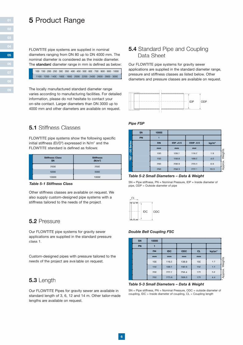
FLOWTITE pipe systems are supplied in nominal diameters ranging from DN 80 up to DN 4000 mm. The nominal diameter is considered as the inside diameter.The standard diameter range in mm is defined as below:
The locally manufactured standard diameter range varies according to manufacturing facilities. For detailed information, please do not hesitate to contact youron-site contact. Larger diameters than DN 3000 up to 4000 mm and other diameters are available on request.
5.1 Stiffness Classes
FLOWTITE pipe systems show the following specific initial stiffness (EI/D3) expressed in N/m2 and the FLOWTITE standard is defined as follows:
Other stiffness classes are available on request. We also supply custom-designed pipe systems with a stiffness tailored to the needs of the project.
5.2 Pressure
Our FLOWTITE pipe systems for gravity sewer applications are supplied in the standard pressure class 1.
Custom-designed pipes with pressure tailored to the needs of the project are available on request.
5.3 Length
Our FLOWTITE Pipes for gravity sewer are available in standard length of 3, 6, 12 and 14 m. Other tailor-made lengths are available on request.
Stiffness ClassSN
Stiffness(N/m2)
2500 2500
5000 5000
10000 10000
Table 5-1 Stiffness Class
5 Product Range
100 · 150 · 200 · 250 · 300 · 350 · 400 · 450 · 500 · 600 · 700 · 800 · 900 · 1000
1100 · 1200 · 1400 · 1600 · 1800 · 2000 · 2200 · 2400 · 2600 · 2800 · 3000
05
Table 5-3 Small Diameters – Data & Weight
SN = Pipe stiffness, PN = Nominal Pressure, ODC = outside diameter of coupling, IDC = Inside diameter of coupling, CL = Coupling length
SN 10000
PN 1
DN IDC ODC CL kg/pc*
mm mm mm mm
100 116.5 138.9 150 1.2
150 168.5 190.9 150 1.5
200 222.0 256.4 175 3.6
250 273.6 308.0 175 4.4
* A
pp
rox.
Wei
ghts
IDP ODP
CL
IDC ODC
Table 5-2 Small Diameters – Data & Weight
SN = Pipe stiffness, PN = Nominal Pressure, IDP = Inside diameter of pipe, ODP = Outside diameter of pipe
SN 10000
PN 1
DN IDP +0.5 ODP -0.5 kg/m*
mm mm mm
100 109.2 116.0 1.9
150 158.8 168.0 4.0
200 208.9 220.5 6.9
250 258.3 272.1 10.3
* A
pp
rox.
Wei
ghts
“B2”
– O
D S
erie
s
Pipe FSP
Double Bell Coupling FSC
5.4 Standard Pipe and Coupling Data Sheet
Our FLOWTITE pipe systems for gravity sewer applications are supplied in the standard diameter range,pressure and stiffness classes as listed below. Other diameters and pressure classes are available on request.
7
01
02
03
04
06
07
08
09
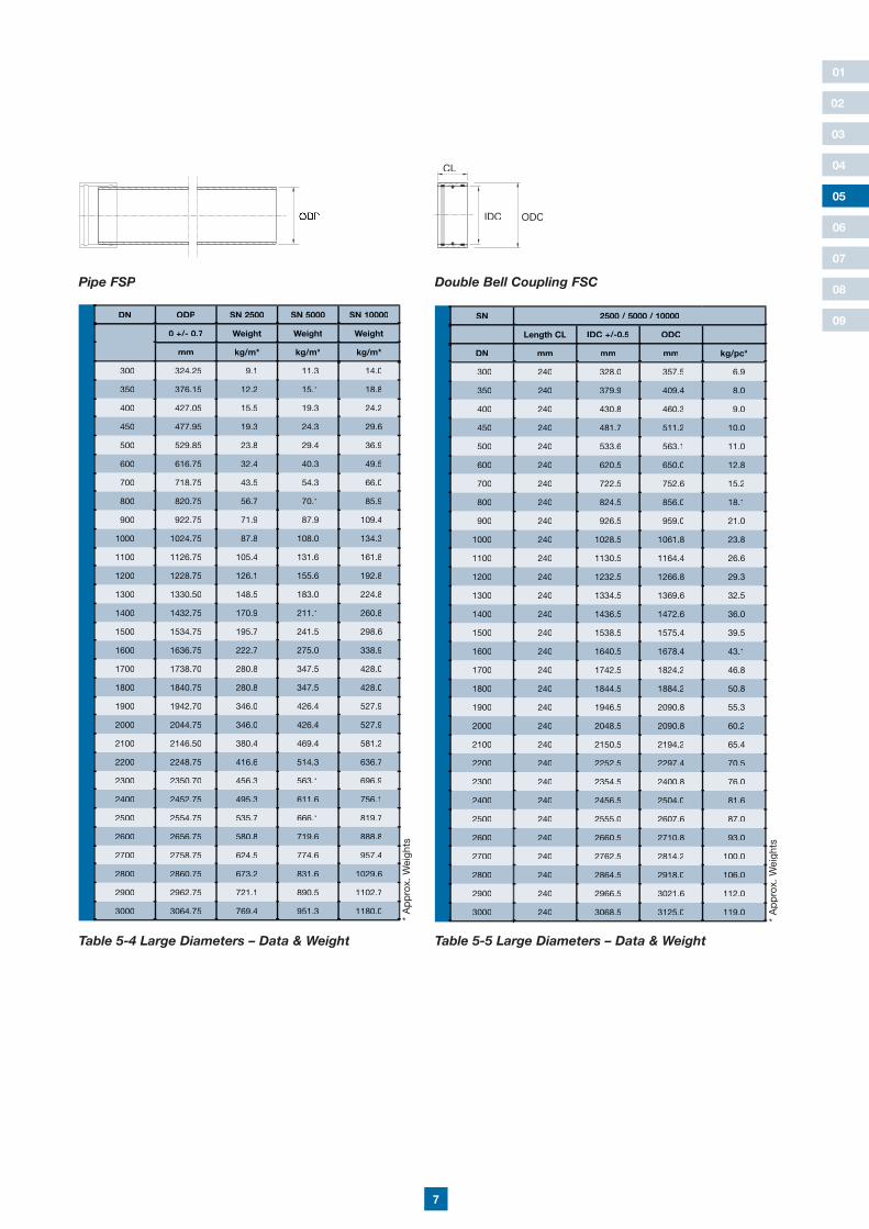
Table 5-5 Large Diameters – Data & Weight
05
SN 2500 / 5000 / 10000
Length CL IDC +/-0.5 ODC
DN mm mm mm kg/pc*
300 240 328.0 357.5 6.9
350 240 379.9 409.4 8.0
400 240 430.8 460.3 9.0
450 240 481.7 511.2 10.0
500 240 533.6 563.1 11.0
600 240 620.5 650.0 12.8
700 240 722.5 752.6 15.2
800 240 824.5 856.0 18.1
900 240 926.5 959.0 21.0
1000 240 1028.5 1061.8 23.8
1100 240 1130.5 1164.4 26.6
1200 240 1232.5 1266.8 29.3
1300 240 1334.5 1369.6 32.5
1400 240 1436.5 1472.6 36.0
1500 240 1538.5 1575.4 39.5
1600 240 1640.5 1678.4 43.1
1700 240 1742.5 1824.2 46.8
1800 240 1844.5 1884.2 50.8
1900 240 1946.5 2090.8 55.3
2000 240 2048.5 2090.8 60.2
2100 240 2150.5 2194.2 65.4
2200 240 2252.5 2297.4 70.5
2300 240 2354.5 2400.8 76.0
2400 240 2456.5 2504.0 81.6
2500 240 2555.0 2607.6 87.0
2600 240 2660.5 2710.8 93.0
2700 240 2762.5 2814.2 100.0
2800 240 2864.5 2918.0 106.0
2900 240 2966.5 3021.6 112.0
3000 240 3068.5 3125.0 119.0
* A
pp
rox.
Wei
ghts
Double Bell Coupling FSC
Table 5-4 Large Diameters – Data & Weight
DN ODP SN 2500 SN 5000 SN 10000
0 +/- 0.7 Weight Weight Weight
mm kg/m* kg/m* kg/m*
300 324.25 9.1 11.3 14.0
350 376.15 12.2 15.1 18.8
400 427.05 15.5 19.3 24.2
450 477.95 19.3 24.3 29.6
500 529.85 23.8 29.4 36.9
600 616.75 32.4 40.3 49.5
700 718.75 43.5 54.3 66.0
800 820.75 56.7 70.1 85.9
900 922.75 71.9 87.9 109.4
1000 1024.75 87.8 108.0 134.3
1100 1126.75 105.4 131.6 161.8
1200 1228.75 126.1 155.6 192.8
1300 1330.50 148.5 183.0 224.8
1400 1432.75 170.9 211.1 260.8
1500 1534.75 195.7 241.5 298.6
1600 1636.75 222.7 275.0 338.9
1700 1738.70 280.8 347.5 428.0
1800 1840.75 280.8 347.5 428.0
1900 1942.70 346.0 426.4 527.9
2000 2044.75 346.0 426.4 527.9
2100 2146.50 380.4 469.4 581.2
2200 2248.75 416.6 514.3 636.7
2300 2350.70 456.3 563.1 696.9
2400 2452.75 495.3 611.6 756.1
2500 2554.75 535.7 666.1 819.7
2600 2656.75 580.8 719.6 888.8
2700 2758.75 624.5 774.6 957.4
2800 2860.75 673.2 831.6 1029.6
2900 2962.75 721.1 890.5 1102.7
3000 3064.75 769.4 951.3 1180.0
* A
pp
rox.
Wei
ghts
Pipe FSP
ODP
CL
IDC ODC
8
01
02
03
04
07
08
09
05
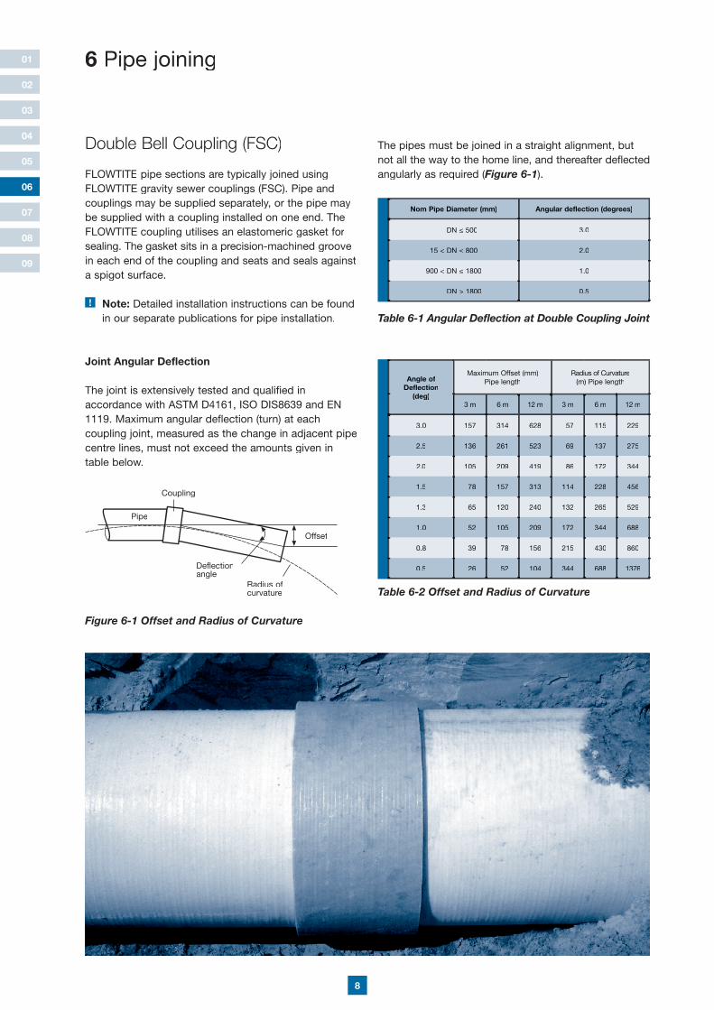
6 Pipe joining
Double Bell Coupling (FSC)
FLOWTITE pipe sections are typically joined using FLOWTITE gravity sewer couplings (FSC). Pipe and couplings may be supplied separately, or the pipe may be supplied with a coupling installed on one end. The FLOWTITE coupling utilises an elastomeric gasket for sealing. The gasket sits in a precision-machined groove in each end of the coupling and seats and seals against a spigot surface.
! Note: Detailed installation instructions can be found in our separate publications for pipe installation.
Joint Angular Deflection
The joint is extensively tested and qualified in accordance with ASTM D4161, ISO DIS8639 and EN 1119. Maximum angular deflection (turn) at each coupling joint, measured as the change in adjacent pipe centre lines, must not exceed the amounts given in table below.
Figure 6-1 Offset and Radius of Curvature
Coupling
Offset
Radius ofcurvature
Deflectionangle
Pipe
Angle of Deflection
(deg)
Maximum Offset (mm)Pipe length
Radius of Curvature(m) Pipe length
3 m 6 m 12 m 3 m 6 m 12 m
3.0 157 314 628 57 115 229
2.5 136 261 523 69 137 275
2.0 105 209 419 86 172 344
1.5 78 157 313 114 228 456
1.3 65 120 240 132 265 529
1.0 52 105 209 172 344 688
0.8 39 78 156 215 430 860
0.5 26 52 104 344 688 1376
Table 6-2 Offset and Radius of Curvature
06
The pipes must be joined in a straight alignment, but not all the way to the home line, and thereafter deflected angularly as required (Figure 6-1angularly as required (Figure 6-1angularly as required ( ).
Nom Pipe Diameter (mm) Angular deflection (degrees)
DN ≤ 500 3.0
15 < DN ≤ 800 2.0
900 < DN ≤ 1800 1.0
DN > 1800 0.5
Table 6-1 Angular Deflection at Double Coupling Joint
9
01
02
03
04
05
06
08
09
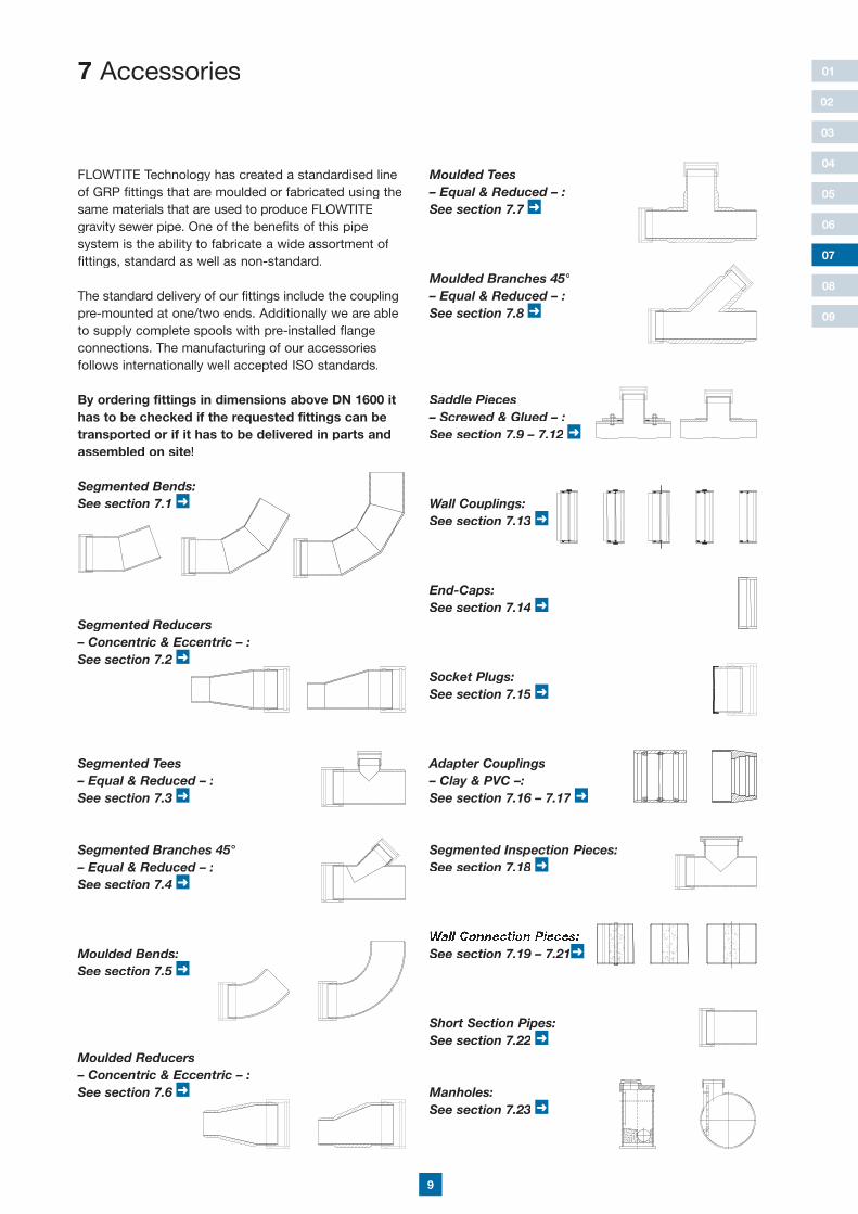
7 Accessories
FLOWTITE Technology has created a standardised line of GRP fittings that are moulded or fabricated using the same materials that are used to produce FLOWTITEgravity sewer pipe. One of the benefits of this pipe system is the ability to fabricate a wide assortment of fittings, standard as well as non-standard.
The standard delivery of our fittings include the coupling pre-mounted at one/two ends. Additionally we are able to supply complete spools with pre-installed flange connections. The manufacturing of our accessories follows internationally well accepted ISO standards.
By ordering fittings in dimensions above DN 1600 it has to be checked if the requested fittings can be transported or if it has to be delivered in parts and assembled on site!
Segmented Bends:See section 7.1 ➜
Segmented Tees– Equal & Reduced – :See section 7.3 ➜
Moulded Tees– Equal & Reduced – :See section 7.7 ➜
Moulded Bends:See section 7.5 ➜
07
Segmented Reducers– Concentric & Eccentric – :See section 7.2 ➜
Segmented Branches 45°– Equal & Reduced – :See section 7.4 ➜
Moulded Reducers– Concentric & Eccentric – :See section 7.6 ➜
Moulded Branches 45°– Equal & Reduced – :See section 7.8 ➜
Segmented Inspection Pieces:See section 7.18 ➜
Manholes:See section 7.23 ➜
End-Caps:See section 7.14 ➜
Socket Plugs:See section 7.15 ➜
Saddle Pieces– Screwed & Glued – :See section 7.9 – 7.12 ➜
Wall Couplings:See section 7.13 ➜
Short Section Pipes:See section 7.22 ➜
Wall Connection Pieces:See section 7.19 – 7.21➜
Adapter Couplings– Clay & PVC –:See section 7.16 – 7.17 ➜
B pyT C pyT 0 pyT 00 pyTA pyT
10
01
02
03
04
05
06
08
09
Angle
”B2“ OD Series 11.25° 15° 22.5° 30° 45° 60° 90°
DN No. of Mitres with Laying Length (LL)
mm 1 1 1 1 2 2 3
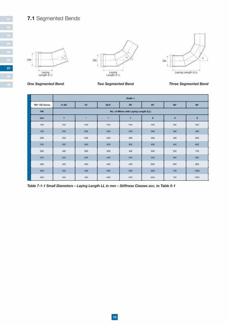
100 250 250 250 250 250 300 350
150 250 250 250 250 300 300 400
200 250 250 250 300 350 400 500
250 300 300 300 300 400 450 600
300 400 350 400 400 500 550 750
350 400 400 400 450 550 600 800
400 450 450 450 450 600 650 900
450 450 450 500 500 600 700 1000
500 450 450 500 500 650 750 1050
Table 7-1-1 Small Diameters – Laying Length LL in mm – Stiffness Classes acc. to Table 5-1
One Segmented Bend Two Segmented Bend Three Segmented Bend
7.1 Segmented Bends
LayingLength (LL)L)L
DN
LayingLength (LL)L)L
DN
Laying Length (LL)L)L
DN
07
11
01
02
03
04
05
06
08
09
07
Angle
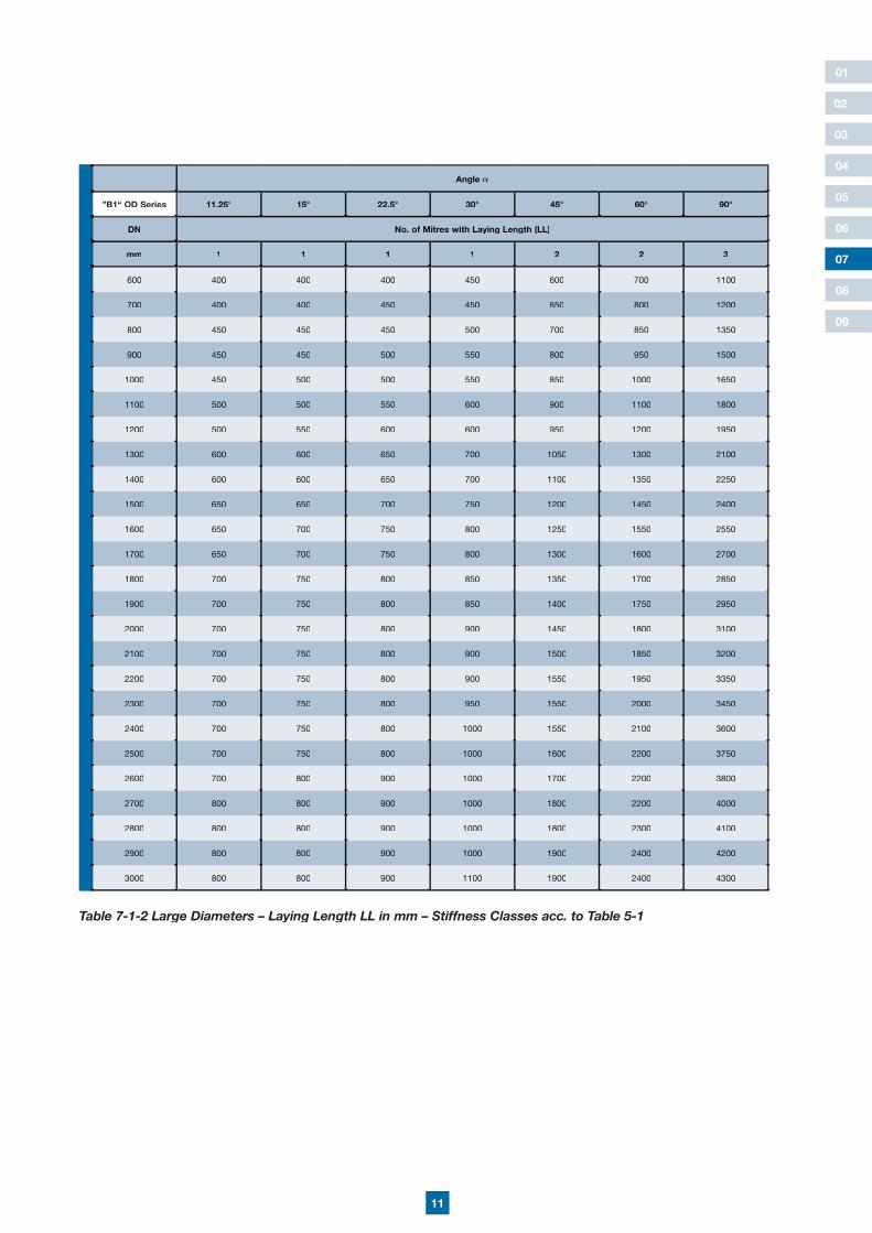
”B1“ OD Series 11.25° 15° 22.5° 30° 45° 60° 90°
DN No. of Mitres with Laying Length (LL)
mm 1 1 1 1 2 2 3
600 400 400 400 450 600 700 1100
700 400 400 450 450 650 800 1200
800 450 450 450 500 700 850 1350
900 450 450 500 550 800 950 1500
1000 450 500 500 550 850 1000 1650
1100 500 500 550 600 900 1100 1800
1200 500 550 600 600 950 1200 1950
1300 600 600 650 700 1050 1300 2100
1400 600 600 650 700 1100 1350 2250
1500 650 650 700 750 1200 1450 2400
1600 650 700 750 800 1250 1550 2550
1700 650 700 750 800 1300 1600 2700
1800 700 750 800 850 1350 1700 2850
1900 700 750 800 850 1400 1750 2950
2000 700 750 800 900 1450 1800 3100
2100 700 750 800 900 1500 1850 3200
2200 700 750 800 900 1550 1950 3350
2300 700 750 800 950 1550 2000 3450
2400 700 750 800 1000 1550 2100 3600
2500 700 750 800 1000 1600 2200 3750
2600 700 800 900 1000 1700 2200 3800
2700 800 800 900 1000 1800 2200 4000
2800 800 800 900 1000 1800 2300 4100
2900 800 800 900 1000 1900 2400 4200
3000 800 800 900 1100 1900 2400 4300
Table 7-1-2 Large Diameters – Laying Length LL in mm – Stiffness Classes acc. to Table 5-1
12
01
02
03
04
05
06
08
09
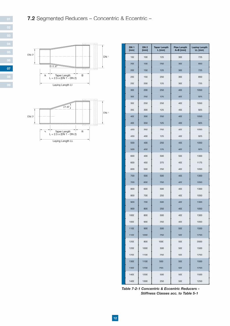
A BTaper LengthL = 2.5 x (DN 1 - DN 2)
11.4°
DN 2DN 1
DN 1 [mm]
DN 2 [mm]
Taper LengthL [mm]
Pipe LengthA=B [mm]
Laying LengthLL [mm]
150 100 125 300 725
200 100 250 300 850
200 150 125 300 725
250 150 250 300 850
250 200 125 300 725
300 200 250 400 1050
300 250 125 400 925
350 250 250 400 1050
350 300 125 400 925
400 300 250 400 1050
400 350 125 400 925
450 350 250 400 1050
450 400 125 400 925
500 400 250 400 1050
500 450 125 400 925
600 400 500 500 1300
600 450 375 400 1175
600 500 250 400 1050
700 500 500 400 1300
700 600 250 400 1050
800 600 500 400 1300
800 700 250 400 1050
900 700 500 400 1300
900 800 250 400 1050
1000 800 500 400 1300
1000 900 250 400 1050
1100 900 500 500 1500
1100 1000 250 500 1250
1200 800 1000 500 2000
1200 1000 500 500 1500
1200 1100 250 500 1250
1300 1100 500 500 1500
1300 1200 250 500 1250
1400 1200 500 500 1500
1400 1300 250 500 1250
Table 7-2-1 Concentric & Eccentric Reducers – Stiffness Classes acc. to Table 5-1
7.2 Segmented Reducers – Concentric & Eccentric –
Laying Length LL
07
A BTaper LengthL = 2.5 x (DN 1 - DN 2)
21.6°
DN 2DN 1
Laying Length LL
13
01
02
03
04
05
06
08
09
07
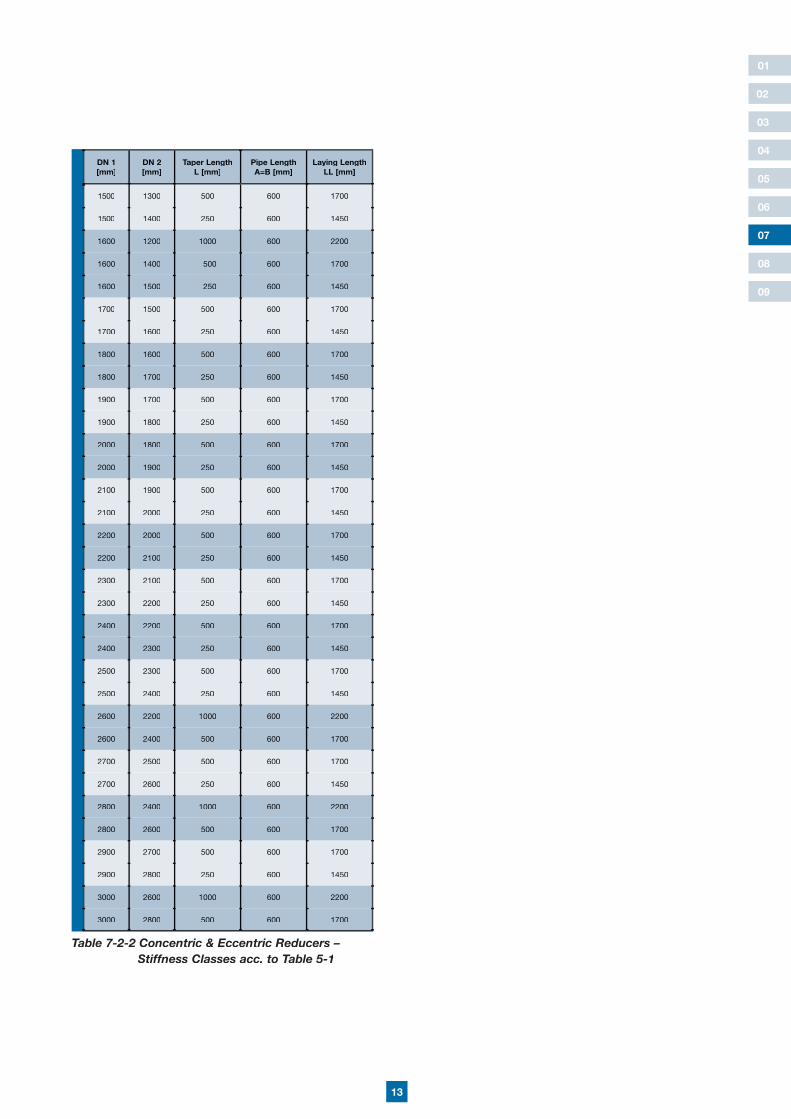
DN 1 [mm]
DN 2 [mm]
Taper LengthL [mm]
Pipe LengthA=B [mm]
Laying LengthLL [mm]
1500 1300 500 600 1700
1500 1400 250 600 1450
1600 1200 1000 600 2200
1600 1400 500 600 1700
1600 1500 250 600 1450
1700 1500 500 600 1700
1700 1600 250 600 1450
1800 1600 500 600 1700
1800 1700 250 600 1450
1900 1700 500 600 1700
1900 1800 250 600 1450
2000 1800 500 600 1700
2000 1900 250 600 1450
2100 1900 500 600 1700
2100 2000 250 600 1450
2200 2000 500 600 1700
2200 2100 250 600 1450
2300 2100 500 600 1700
2300 2200 250 600 1450
2400 2200 500 600 1700
2400 2300 250 600 1450
2500 2300 500 600 1700
2500 2400 250 600 1450
2600 2200 1000 600 2200
2600 2400 500 600 1700
2700 2500 500 600 1700
2700 2600 250 600 1450
2800 2400 1000 600 2200
2800 2600 500 600 1700
2900 2700 500 600 1700
2900 2800 250 600 1450
3000 2600 1000 600 2200
3000 2800 500 600 1700
Table 7-2-2 Concentric & Eccentric Reducers – Stiffness Classes acc. to Table 5-1
14
01
02
03
04
05
06
08
09
07
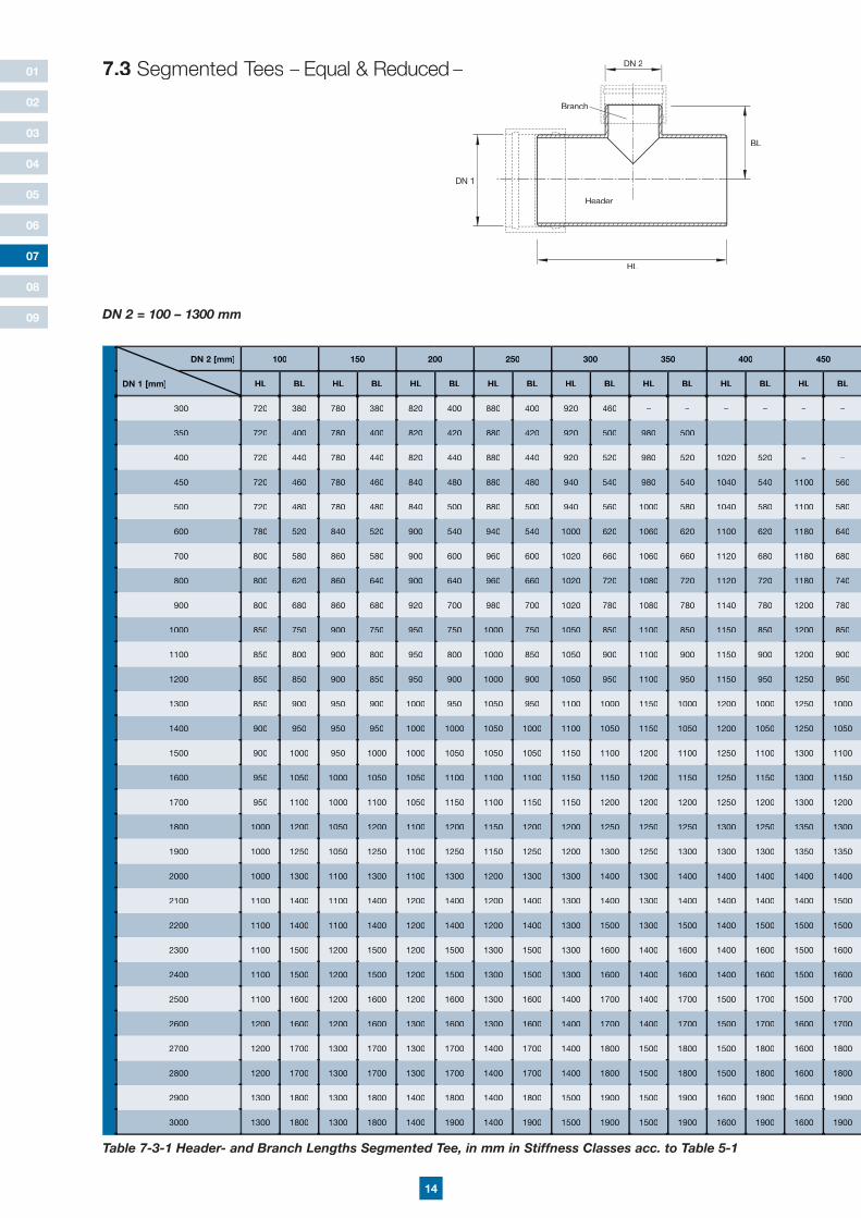
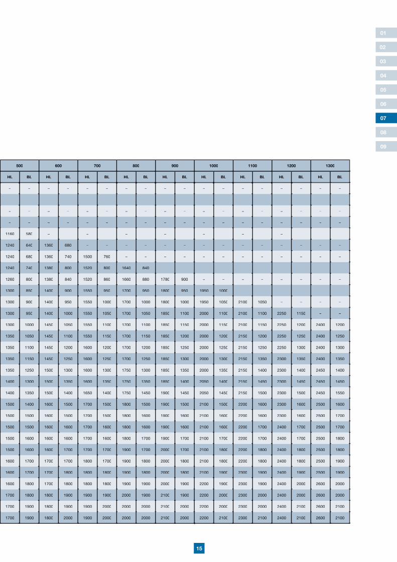
Table 7-3-1 Header- and Branch Lengths Segmented Tee, in mm in Stiffness Classes acc. to Table 5-1
7.3 Segmented Tees – Equal & Reduced –
HL
BL
Header
Branch
DN 2
DN 1
DN 2 = 100 – 1300 mm
DN 2 [mm] 100 150 200 250 300 350 400 450
DN 1 [mm] HL BL HL BL HL BL HL BL HL BL HL BL HL BL HL BL
300 720 380 780 380 820 400 880 400 920 460 – – – – – –
350 720 400 780 400 820 420 880 420 920 500 980 500 – – – –
400 720 440 780 440 820 440 880 440 920 520 980 520 1020 520 – –
450 720 460 780 460 840 480 880 480 940 540 980 540 1040 540 1100 560
500 720 480 780 480 840 500 880 500 940 560 1000 580 1040 580 1100 580
600 780 520 840 520 900 540 940 540 1000 620 1060 620 1100 620 1180 640
700 800 580 860 580 900 600 960 600 1020 660 1060 660 1120 680 1180 680
800 800 620 860 640 900 640 960 660 1020 720 1080 720 1120 720 1180 740
900 800 680 860 680 920 700 980 700 1020 780 1080 780 1140 780 1200 780
1000 850 750 900 750 950 750 1000 750 1050 850 1100 850 1150 850 1200 850
1100 850 800 900 800 950 800 1000 850 1050 900 1100 900 1150 900 1200 900
1200 850 850 900 850 950 900 1000 900 1050 950 1100 950 1150 950 1250 950
1300 850 900 950 900 1000 950 1050 950 1100 1000 1150 1000 1200 1000 1250 1000
1400 900 950 950 950 1000 1000 1050 1000 1100 1050 1150 1050 1200 1050 1250 1050
1500 900 1000 950 1000 1000 1050 1050 1050 1150 1100 1200 1100 1250 1100 1300 1100
1600 950 1050 1000 1050 1050 1100 1100 1100 1150 1150 1200 1150 1250 1150 1300 1150
1700 950 1100 1000 1100 1050 1150 1100 1150 1150 1200 1200 1200 1250 1200 1300 1200
1800 1000 1200 1050 1200 1100 1200 1150 1200 1200 1250 1250 1250 1300 1250 1350 1300
1900 1000 1250 1050 1250 1100 1250 1150 1250 1200 1300 1250 1300 1300 1300 1350 1350
2000 1000 1300 1100 1300 1100 1300 1200 1300 1300 1400 1300 1400 1400 1400 1400 1400
2100 1100 1400 1100 1400 1200 1400 1200 1400 1300 1400 1300 1400 1400 1400 1400 1500
2200 1100 1400 1100 1400 1200 1400 1200 1400 1300 1500 1300 1500 1400 1500 1500 1500
2300 1100 1500 1200 1500 1200 1500 1300 1500 1300 1600 1400 1600 1400 1600 1500 1600
2400 1100 1500 1200 1500 1200 1500 1300 1500 1300 1600 1400 1600 1400 1600 1500 1600
2500 1100 1600 1200 1600 1200 1600 1300 1600 1400 1700 1400 1700 1500 1700 1500 1700
2600 1200 1600 1200 1600 1300 1600 1300 1600 1400 1700 1400 1700 1500 1700 1600 1700
2700 1200 1700 1300 1700 1300 1700 1400 1700 1400 1800 1500 1800 1500 1800 1600 1800
2800 1200 1700 1300 1700 1300 1700 1400 1700 1400 1800 1500 1800 1500 1800 1600 1800
2900 1300 1800 1300 1800 1400 1800 1400 1800 1500 1900 1500 1900 1600 1900 1600 1900
3000 1300 1800 1300 1800 1400 1900 1400 1900 1500 1900 1500 1900 1600 1900 1600 1900
15
01
02
03
04
05
06
08
09
07
500 600 700 800 900 1000 1100 1200 1300
HL BL HL BL HL BL HL BL HL BL HL BL HL BL HL BL HL BL
– – – – – – – – – – – – – – – – – –
– – – – – – – – – – – – – – – – – –
– – – – – – – – – – – – – – – – – –
– – – – – – – – – – – – – – – – – –
1160 580 – – – – – – – – – – – – – – – –
1240 640 1360 680 – – – – – – – – – – – – – –
1240 680 1360 740 1500 760 – – – – – – – – – – – –
1240 740 1380 800 1520 800 1640 840 – – – – – – – – – –
1260 800 1380 840 1520 860 1660 880 1780 900 – – – – – – – –
1300 850 1400 900 1550 950 1700 950 1800 950 1950 1000 – – – – – –
1300 900 1400 950 1550 1000 1700 1000 1800 1000 1950 1050 2100 1050 – – – –
1300 950 1400 1000 1550 1050 1700 1050 1850 1100 2000 1100 2100 1100 2250 1150 – –
1300 1000 1450 1050 1550 1100 1700 1100 1850 1150 2000 1150 2100 1150 2250 1200 2400 1200
1350 1050 1450 1100 1550 1150 1700 1150 1850 1200 2000 1200 2150 1200 2250 1250 2400 1250
1350 1100 1450 1200 1600 1200 1700 1200 1850 1250 2000 1250 2150 1250 2250 1300 2400 1300
1350 1150 1450 1250 1600 1250 1700 1250 1850 1300 2000 1300 2150 1350 2300 1350 2400 1350
1350 1250 1500 1300 1600 1300 1750 1300 1850 1350 2000 1350 2150 1400 2300 1400 2450 1400
1400 1300 1500 1350 1600 1350 1750 1350 1850 1400 2050 1400 2150 1450 2300 1450 2450 1450
1400 1350 1500 1400 1650 1400 1750 1450 1900 1450 2050 1450 2150 1500 2300 1500 2450 1550
1500 1400 1600 1500 1700 1500 1800 1500 1900 1500 2100 1500 2200 1600 2300 1600 2500 1600
1500 1500 1600 1500 1700 1500 1800 1600 1900 1600 2100 1600 2200 1600 2300 1600 2500 1700
1500 1500 1600 1600 1700 1600 1800 1600 1900 1600 2100 1600 2200 1700 2400 1700 2500 1700
1500 1600 1600 1600 1700 1600 1800 1700 1900 1700 2100 1700 2200 1700 2400 1700 2500 1800
1500 1600 1600 1700 1700 1700 1900 1700 2000 1700 2100 1800 2200 1800 2400 1800 2500 1800
1600 1700 1700 1700 1800 1700 1900 1800 2000 1800 2100 1800 2200 1800 2400 1800 2500 1900
1600 1700 1700 1800 1800 1800 1900 1800 2000 1800 2100 1900 2300 1900 2400 1900 2500 1900
1600 1800 1700 1800 1800 1800 1900 1900 2000 1900 2200 1900 2300 1900 2400 2000 2600 2000
1700 1800 1800 1900 1900 1900 2000 1900 2100 1900 2200 2000 2300 2000 2400 2000 2600 2000
1700 1900 1800 1900 1900 2000 2000 2000 2100 2000 2200 2000 2300 2000 2400 2100 2600 2100
1700 1900 1800 2000 1900 2000 2000 2000 2100 2000 2200 2100 2300 2100 2400 2100 2600 2100
16
01
02
03
04
05
06
08
09
07
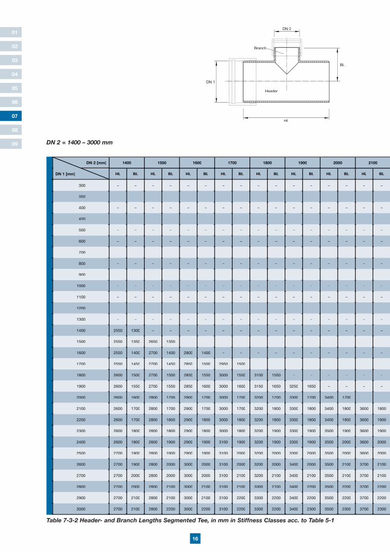
Table 7-3-2 Header- and Branch Lengths Segmented Tee, in mm in Stiffness Classes acc. to Table 5-1
HL
BL
Header
Branch
DN 2
DN 1
DN 2 = 1400 – 3000 mm
DN 2 [mm] 1400 1500 1600 1700 1800 1900 2000 2100
DN 1 [mm] HL BL HL BL HL BL HL BL HL BL HL BL HL BL HL BL
300 – – – – – – – – – – – – – – – –
350 – – – – – – – – – – – – – – – –
400 – – – – – – – – – – – – – – – –
450 – – – – – – – – – – – – – – – –
500 – – – – – – – – – – – – – – – –
600 – – – – – – – – – – – – – – – –
700 – – – – – – – – – – – – – – – –
800 – – – – – – – – – – – – – – – –
900 – – – – – – – – – – – – – – – –
1000 – – – – – – – – – – – – – – – –
1100 – – – – – – – – – – – – – – – –
1200 – – – – – – – – – – – – – – – –
1300 – – – – – – – – – – – – – – – –
1400 2550 1300 – – – – – – – – – – – – – –
1500 2550 1350 2650 1350 – – – – – – – – – – – –
1600 2550 1400 2700 1400 2800 1400 – – – – – – – – – –
1700 2550 1450 2700 1450 2850 1500 2950 1500 – – – – – – – –
1800 2600 1500 2700 1500 2850 1550 3000 1550 3100 1550 – – – – – –
1900 2600 1550 2700 1550 2850 1600 3000 1600 3150 1650 3250 1650 – – – –
2000 2600 1600 2800 1700 2900 1700 3000 1700 3200 1700 3300 1700 3400 1700 – –
2100 2600 1700 2800 1700 2900 1700 3000 1700 3200 1800 3300 1800 3400 1800 3600 1800
2200 2600 1700 2800 1800 2900 1800 3000 1800 3200 1800 3300 1800 3400 1800 3600 1900
2300 2600 1800 2800 1800 2900 1800 3000 1800 3200 1900 3300 1900 3500 1900 3600 1900
2400 2600 1800 2800 1900 2900 1900 3100 1900 3200 1900 3300 1900 3500 2000 3600 2000
2500 2700 1900 2800 1900 2900 1900 3100 2000 3200 2000 3300 2000 3500 2000 3600 2000
2600 2700 1900 2800 2000 3000 2000 3100 2000 3200 2000 3400 2000 3500 2100 3700 2100
2700 2700 2000 2800 2000 3000 2000 3100 2100 3200 2100 3400 2100 3500 2100 3700 2100
2800 2700 2000 2800 2100 3000 2100 3100 2100 3300 2100 3400 2200 3500 2200 3700 2200
2900 2700 2100 2800 2100 3000 2100 3100 2200 3300 2200 3400 2200 3500 2200 3700 2200
3000 2700 2100 2800 2200 3000 2200 3100 2200 3300 2200 3400 2300 3500 2300 3700 2300

17
01
02
03
04
05
06
08
09
07
2200 2300 2400 2500 2600 2700 2800 2900 3000
HL BL HL BL HL BL HL BL HL BL HL BL HL BL HL BL HL BL
– – – – – – – – – – – – – – – – – –
– – – – – – – – – – – – – – – – – –
– – – – – – – – – – – – – – – – – –
– – – – – – – – – – – – – – – – – –
– – – – – – – – – – – – – – – – – –
– – – – – – – – – – – – – – – – – –
– – – – – – – – – – – – – – – – – –
– – – – – – – – – – – – – – – – – –
– – – – – – – – – – – – – – – – – –
– – – – – – – – – – – – – – – – – –
– – – – – – – – – – – – – – – – – –
– – – – – – – – – – – – – – – – – –
– – – – – – – – – – – – – – – – – –
– – – – – – – – – – – – – – – – – –
– – – – – – – – – – – – – – – – – –
– – – – – – – – – – – – – – – – – –
– – – – – – – – – – – – – – – – – –
– – – – – – – – – – – – – – – – – –
– – – – – – – – – – – – – – – – – –
– – – – – – – – – – – – – – – – – –
– – – – – – – – – – – – – – – – – –
3700 1900 – – – – – – – – – – – – – – – –
3700 1900 3900 2000 – – – – – – – – – – – – – –
3700 2000 3900 2000 4000 2000 – – – – – – – – – – – –
3800 2000 3900 2100 4000 2100 4200 2100 – – – – – – – – – –
3800 2100 3900 2100 4100 2100 4200 2200 4300 2200 – – – – – – – –
3800 2200 3900 2200 4100 2200 4200 2200 4300 2200 4500 2300 – – – – – –
3800 2200 3900 2200 4100 2200 4200 2300 4300 2300 4500 2300 4600 2300 – – – –
3800 2300 4000 2300 4100 2300 4200 2300 4400 2400 4500 2400 4600 2400 4800 2400 – –
3800 2300 4000 2300 4100 2400 4200 2400 4400 2400 4500 2400 4600 2400 4800 2500 4900 2500

18
01
02
03
04
05
06
08
09
07
Table 7-4-1 Header- and Branch Lengths Segmented Branches 45°, in mm in Stiffness Classes acc. to Table 5-1
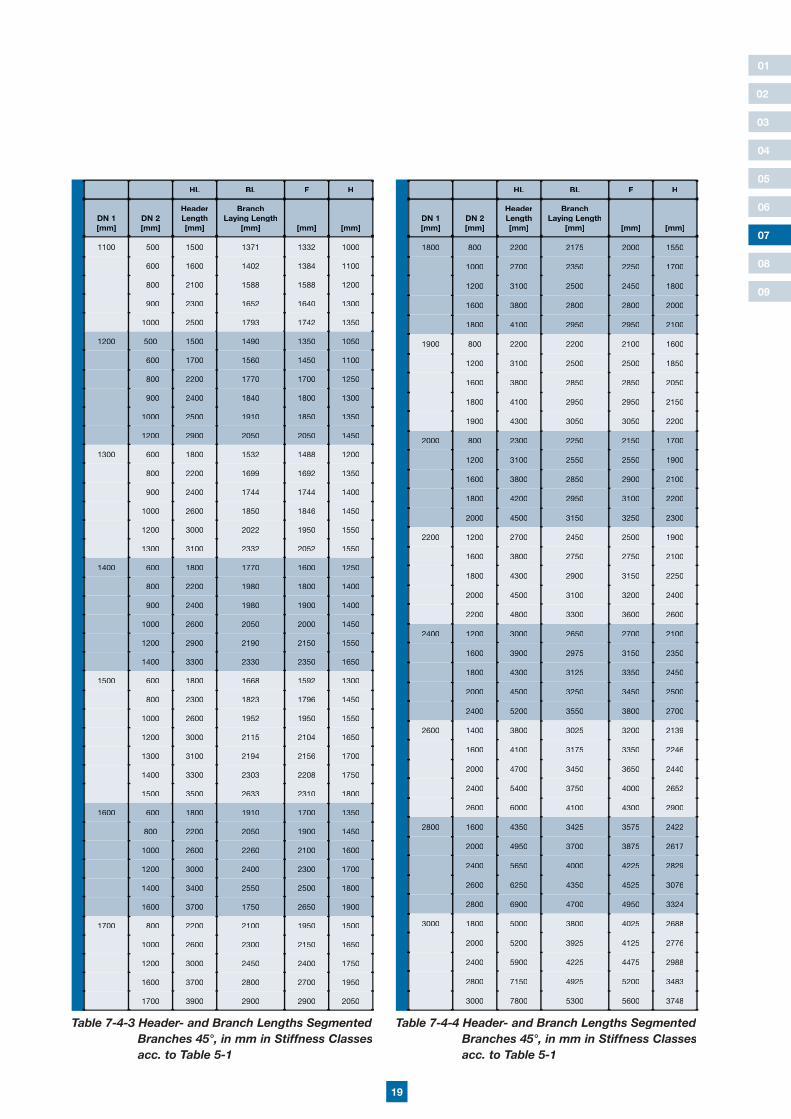
7.4 Segmented Branches 45° – Equal & Reduced –
HL
H
Header
Branch
BL
DN 1
HL BL F H
DN 1 [mm]
DN 2 [mm]
HeaderLength [mm]
BranchLaying Length
[mm] [mm] [mm]
100 100 600 420 350 300
150 100 600 420 375 300
150 700 420 425 300
200 100 600 420 400 300
150 700 500 450 350
200 800 500 500 350
250 100 600 500 425 350
150 700 500 475 350
200 800 570 525 400
250 900 570 575 400
300 100 700 500 500 350
150 800 570 550 400
200 900 570 600 400
250 1000 640 650 450
300 1100 710 700 500
350 100 700 570 550 400
150 800 570 575 400
200 900 640 625 450
250 1000 640 675 450
300 1100 710 725 500
350 1200 780 775 550
400 100 700 570 550 400
150 800 640 600 450
200 900 640 650 450
250 1000 710 700 500
300 1100 780 750 550
350 1200 850 800 600
400 1300 850 850 600
HL BL F H
DN 1 [mm]
DN 2 [mm]
HeaderLength [mm]
BranchLaying Length
[mm] [mm] [mm]
500 100 700 710 600 500
150 800 710 650 500
200 900 780 700 550
250 1000 780 750 550
300 1100 850 800 600
350 1200 920 850 650
400 1300 920 900 650
500 1500 990 1000 700
600 300 1100 920 850 650
400 1300 990 950 700
500 1500 1060 1050 750
600 1600 1130 1100 800
700 300 1100 990 900 700
400 1300 1060 1000 750
500 1500 1130 1100 800
600 1700 1200 1200 850
700 1900 1270 1300 900
800 300 1100 1060 950 750
400 1300 1130 1050 800
500 1500 1200 1150 850
600 1700 1270 1250 900
800 2100 1410 1450 1000
900 400 1300 1200 1100 850
500 1500 1270 1200 900
600 1700 1410 1300 1000
700 1900 1490 1400 1050
800 2100 1560 1500 1100
900 2300 1630 1600 1150
1000 400 1300 1270 1150 900
500 1500 1340 1250 950
600 1800 1490 1400 1050
700 1900 1560 1450 1100
800 2100 1630 1550 1150
1000 2500 1770 1750 1250
Table 7-4-2 Header- and Branch Lengths Segmented Branches 45°, in mm in Stiffness Classes acc. to Table 5-1
F
DN 2
= 45°
19
01
02
03
04
05
06
08
09
07
HL BL F H
DN 1 [mm]
DN 2 [mm]
HeaderLength [mm]
BranchLaying Length
[mm] [mm] [mm]
1100 500 1500 1371 1332 1000
600 1600 1402 1384 1100
800 2100 1588 1588 1200
900 2300 1652 1640 1300
1000 2500 1793 1742 1350
1200 500 1500 1490 1350 1050
600 1700 1560 1450 1100
800 2200 1770 1700 1250
900 2400 1840 1800 1300
1000 2500 1910 1850 1350
1200 2900 2050 2050 1450
1300 600 1800 1532 1488 1200
800 2200 1699 1692 1350
900 2400 1744 1744 1400
1000 2600 1850 1846 1450
1200 3000 2022 1950 1550
1300 3100 2332 2052 1550
1400 600 1800 1770 1600 1250
800 2200 1980 1800 1400
900 2400 1980 1900 1400
1000 2600 2050 2000 1450
1200 2900 2190 2150 1550
1400 3300 2330 2350 1650
1500 600 1800 1668 1592 1300
800 2300 1823 1796 1450
1000 2600 1952 1950 1550
1200 3000 2115 2104 1650
1300 3100 2194 2156 1700
1400 3300 2303 2208 1750
1500 3500 2633 2310 1800
1600 600 1800 1910 1700 1350
800 2200 2050 1900 1450
1000 2600 2260 2100 1600
1200 3000 2400 2300 1700
1400 3400 2550 2500 1800
1600 3700 1750 2650 1900
1700 800 2200 2100 1950 1500
1000 2600 2300 2150 1650
1200 3000 2450 2400 1750
1600 3700 2800 2700 1950
1700 3900 2900 2900 2050
HL BL F H
DN 1 [mm]
DN 2 [mm]
HeaderLength [mm]
BranchLaying Length
[mm] [mm] [mm]
1800 800 2200 2175 2000 1550
1000 2700 2350 2250 1700
1200 3100 2500 2450 1800
1600 3800 2800 2800 2000
1800 4100 2950 2950 2100
1900 800 2200 2200 2100 1600
1200 3100 2500 2500 1850
1600 3800 2850 2850 2050
1800 4100 2950 2950 2150
1900 4300 3050 3050 2200
2000 800 2300 2250 2150 1700
1200 3100 2550 2550 1900
1600 3800 2850 2900 2100
1800 4200 2950 3100 2200
2000 4500 3150 3250 2300
2200 1200 2700 2450 2500 1900
1600 3800 2750 2750 2100
1800 4300 2900 3150 2250
2000 4500 3100 3200 2400
2200 4800 3300 3600 2600
2400 1200 3000 2650 2700 2100
1600 3900 2975 3150 2350
1800 4300 3125 3350 2450
2000 4500 3250 3450 2500
2400 5200 3550 3800 2700
2600 1400 3800 3025 3200 2139
1600 4100 3175 3350 2246
2000 4700 3450 3650 2440
2400 5400 3750 4000 2652
2600 6000 4100 4300 2900
2800 1600 4350 3425 3575 2422
2000 4950 3700 3875 2617
2400 5650 4000 4225 2829
2600 6250 4350 4525 3076
2800 6900 4700 4950 3324
3000 1800 5000 3800 4025 2688
2000 5200 3925 4125 2776
2400 5900 4225 4475 2988
2800 7150 4925 5200 3483
3000 7800 5300 5600 3748
Table 7-4-3 Header- and Branch Lengths Segmented Branches 45°, in mm in Stiffness Classes acc. to Table 5-1
Table 7-4-4 Header- and Branch Lengths Segmented Branches 45°, in mm in Stiffness Classes acc. to Table 5-1
20
01
02
03
04
05
06
08
09
07
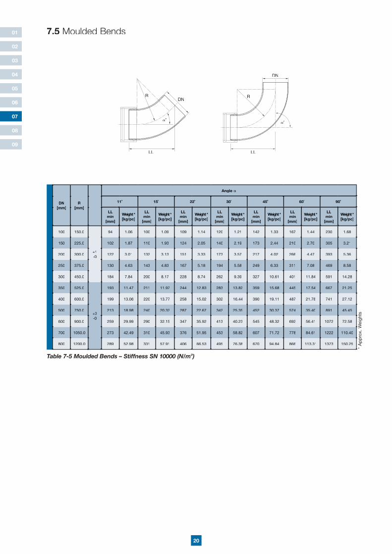
7.5 Moulded Bends
Table 7-5 Moulded Bends – Stiffness SN 10000 (N/m2)2)2
DN[mm]
R[mm]
Angle
11˚ 15˚ 22˚ 30˚ 45˚ 60˚ 90˚
LL min
[mm]
Weight *[kg/pc]
LL min
[mm]
Weight *[kg/pc]
LL min
[mm]
Weight *[kg/pc]
LL min
[mm]
Weight *[kg/pc]
LL min
[mm]
Weight *[kg/pc]
LL min
[mm]
Weight *[kg/pc]
LL min
[mm]
Weight *[kg/pc]
100 150.0
+1-0
94 1.06 100 1.09 109 1.14 120 1.21 142 1.33 167 1.44 230 1.68
150 225.0 102 1.87 110 1.93 124 2.05 140 2.19 173 2.44 210 2.70 305 3.21
200 300.0 122 3.01 132 3.13 151 3.33 173 3.57 217 4.02 266 4.47 393 5.36
250 375.0 130 4.63 143 4.83 167 5.18 194 5.58 249 6.33 311 7.08 469 8.58
300 450.0 184 7.84 200 8.17 228 8.74 262 9.39 327 10.61 401 11.84 591 14.28
350 525.0
+3-0
193 11.47 211 11.97 244 12.83 283 13.82 359 15.68 445 17.54 667 21.25
400 600.0 199 13.06 220 13.77 258 15.02 302 16.44 390 19.11 487 21.78 741 27.12
500 750.0 213 18.98 240 20.32 287 22.67 342 25.35 452 30.37 574 35.40 891 45.45
600 900.0 259 29.99 290 32.15 347 35.92 413 40.23 545 48.32 692 56.41 1072 72.58
700 1050.0 273 42.49 310 45.93 376 51.95 453 58.82 607 71.72 778 84.61 1222 110.40
800 1200.0 289 52.98 331 57.91 406 66.53 495 76.38 670 94.84 866 113.31 1373 150.25
* A
pp
rox.
Wei
ghts
R
LL
DN
°
R
LL
°
DN
21
01
02
03
04
05
06
08
09
07
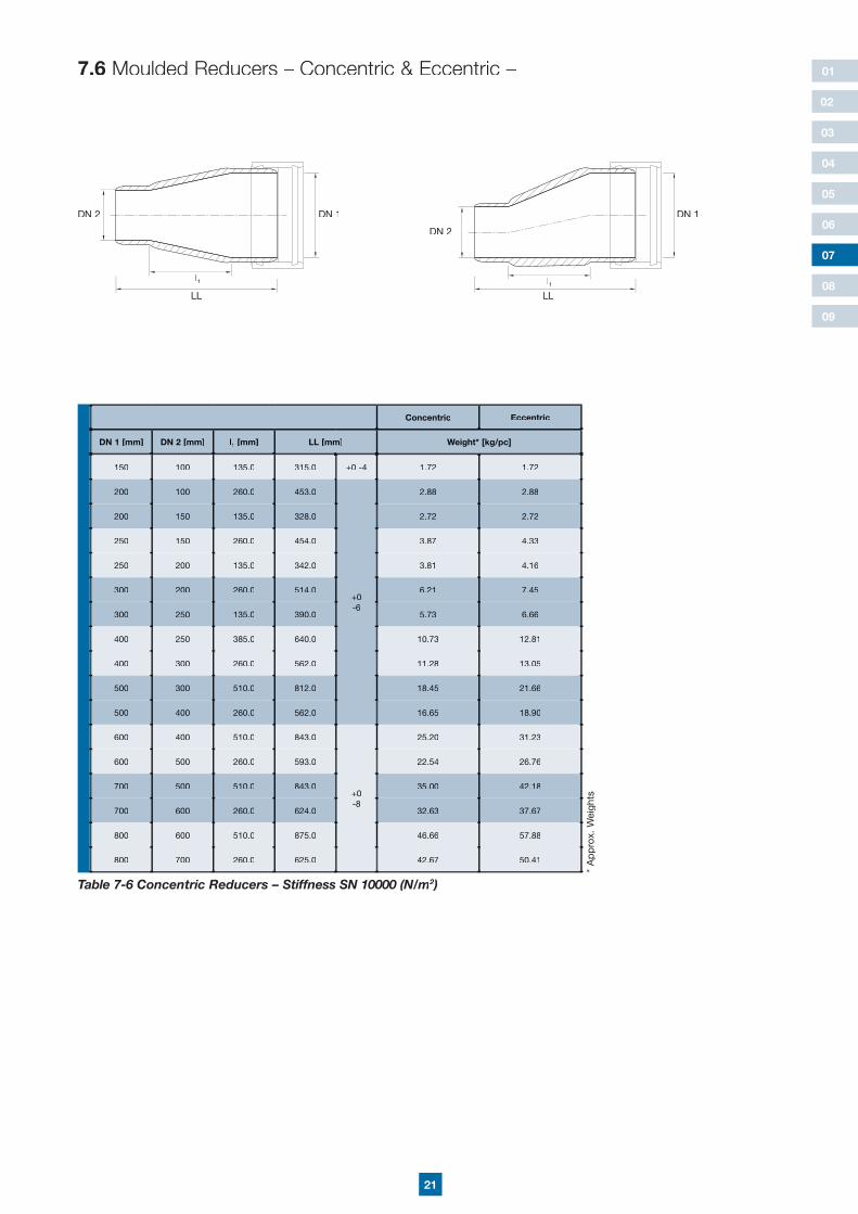
Concentric Eccentric
DN 1 [mm] DN 2 [mm] l1 [mm] LL [mm] Weight* [kg/pc]
150 100 135.0 315.0 +0 -4 1.72 1.72
200 100 260.0 453.0
+0-6
2.88 2.88
200 150 135.0 328.0 2.72 2.72
250 150 260.0 454.0 3.87 4.33
250 200 135.0 342.0 3.81 4.16
300 200 260.0 514.0 6.21 7.45
300 250 135.0 390.0 5.73 6.66
400 250 385.0 640.0 10.73 12.81
400 300 260.0 562.0 11.28 13.05
500 300 510.0 812.0 18.45 21.66
500 400 260.0 562.0 16.65 18.90
600 400 510.0 843.0
+0-8
25.20 31.23
600 500 260.0 593.0 22.54 26.76
700 500 510.0 843.0 35.00 42.18
700 600 260.0 624.0 32.63 37.67
800 600 510.0 875.0 46.66 57.88
800 700 260.0 625.0 42.67 50.41
Table 7-6 Concentric Reducers – Stiffness SN 10000 (N/m2)2)2
7.6 Moulded Reducers – Concentric & Eccentric – Concentric & Eccentric – –
l1
LL
DN 1DN 2
* A
pp
rox.
Wei
ghts
l1LL
DN 1
DN 2
22
01
02
03
04
05
06
08
09
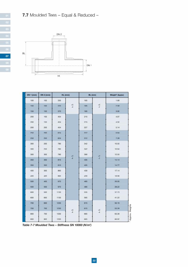
DN 1 [mm] DN 2 [mm] HL [mm] BL [mm] Weight* [kg/pc]
100 100 330
+0-4
165
+0-2
1.68
150 100 370 185 2.58
150 150 370 185 3.00
200 100 454
+0-6
215
+0-3
4.07
200 150 454 215 4.50
200 200 454 227 5.14
250 200 624 312 6.84
250 250 624 312 7.28
300 200 780 342 10.50
300 250 780 342 10.94
300 300 780 390 12.55
350 300 810 405 14.14
350 350 810 405 14.77
400 300 860 430 17.14
400 400 860 430 18.99
500 400 970 485 26.05
500 500 970 485 28.22
600 500 1130 535 37.73
600 600 1130 565 41.22
700 600 1230
+0-8
615
+0-4
50.19
700 700 1230 615 53.28
800 700 1330 665 63.39
800 800 1330 665 66.92
Table 7-7 Moulded Tees – Stiffness SN 10000 (N/m2)2)2
7.7 Moulded Tees – Equal & Reduced –
DN 2
HL
BL
DN 1
* A
pp
rox.
Wei
ghts
07
23
01
02
03
04
05
06
08
09
07
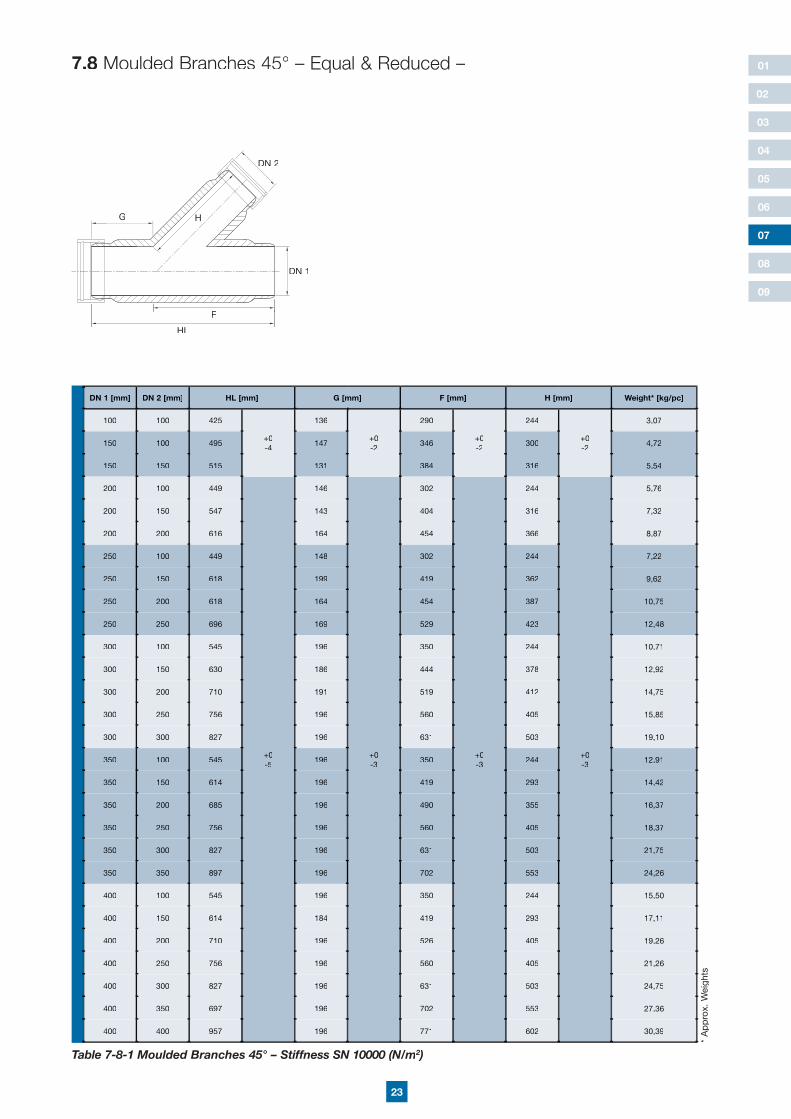
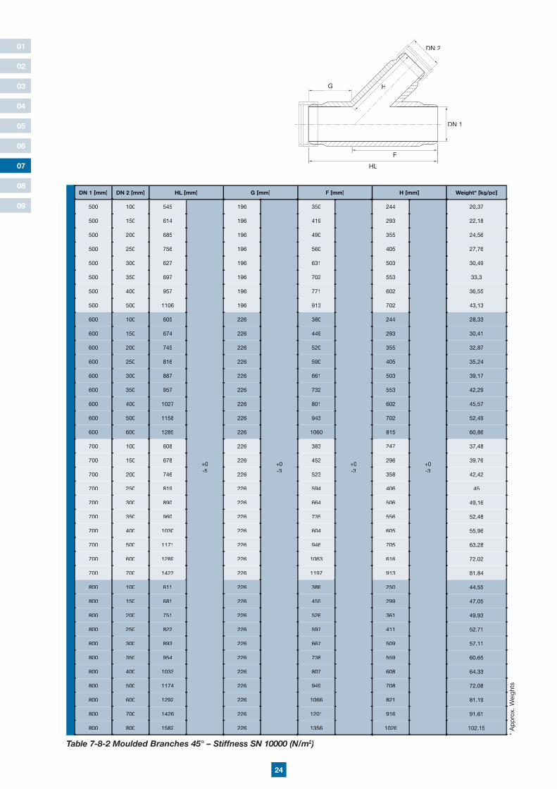
DN 1 [mm] DN 2 [mm] HL [mm] G [mm] F [mm] H [mm] Weight* [kg/pc]
100 100 425
+0-4
136
+0-2
290
+0-2
244
+0-2
3,07
150 100 495 147 346 300 4,72
150 150 515 131 384 316 5,54
200 100 449
+0-5
146
+0-3
302
+0-3
244
+0-3
5,76
200 150 547 143 404 316 7,32
200 200 616 164 454 366 8,87
250 100 449 148 302 244 7,22
250 150 618 199 419 362 9,62
250 200 618 164 454 387 10,75
250 250 696 169 529 423 12,48
300 100 545 196 350 244 10,71
300 150 630 186 444 378 12,92
300 200 710 191 519 412 14,75
300 250 756 196 560 405 15,85
300 300 827 196 631 503 19,10
350 100 545 196 350 244 12,91
350 150 614 196 419 293 14,42
350 200 685 196 490 355 16,37
350 250 756 196 560 405 18,37
350 300 827 196 631 503 21,75
350 350 897 196 702 553 24,26
400 100 545 196 350 244 15,50
400 150 614 184 419 293 17,11
400 200 710 196 526 405 19,26
400 250 756 196 560 405 21,26
400 300 827 196 631 503 24,75
400 350 697 196 702 553 27,36
400 400 957 196 771 602 30,39
Table 7-8-1 Moulded Branches 45° – Stiffness SN 10000 (N/m2)2)2
7.8 Moulded Branches 45° – Equal & Reduced –
* A
pp
rox.
Wei
ghts
DN 2
HL
DN 1
G
F
H
24
01
02
03
04
05
06
08
09
DN 1 [mm] DN 2 [mm] HL [mm] G [mm] F [mm] H [mm] Weight* [kg/pc]
500 100 545
+0-5
196
+0-3
350
+0-3
244
+0-3
20,37
500 150 614 196 419 293 22,18
500 200 685 196 490 355 24,56
500 250 756 196 560 405 27,76
500 300 627 196 631 503 30,49
500 350 697 196 702 553 33,3
500 400 957 196 771 602 36,55
500 500 1106 196 913 702 43,13
600 100 605 226 380 244 28,33
600 150 674 226 449 293 30,41
600 200 745 226 520 355 32,87
600 250 816 226 590 405 35,24
600 300 887 226 661 503 39,17
600 350 957 226 732 553 42,29
600 400 1027 226 801 602 45,57
600 500 1158 226 943 702 52,49
600 600 1285 226 1060 815 60,86
700 100 608 226 383 247 37,48
700 150 678 226 452 296 39,76
700 200 746 226 523 358 42,42
700 250 819 226 594 406 45
700 300 890 226 664 506 49,16
700 350 960 226 735 556 52,48
700 400 1030 226 604 605 55,96
700 500 1171 226 946 705 63,28
700 600 1289 226 1063 616 72,02
700 700 1423 226 1197 913 81,84
800 100 611 226 386 250 44,55
800 150 681 226 455 299 47,05
800 200 751 226 526 361 49,93
800 250 822 226 597 411 52,71
800 300 893 226 667 509 57,11
800 350 954 226 738 559 60,65
800 400 1033 226 807 608 64,33
800 500 1174 226 949 708 72,08
800 600 1292 226 1066 821 81,19
800 700 1426 226 1201 916 91,61
800 800 1582 226 1356 1026 102,15
Table 7-8-2 Moulded Branches 45° – Stiffness SN 10000 (N/m2)2)2
* A
pp
rox.
Wei
ghts
DN 2
HL
DN 1
G
F
H
07
25
01
02
03
04
05
06
08
09
07
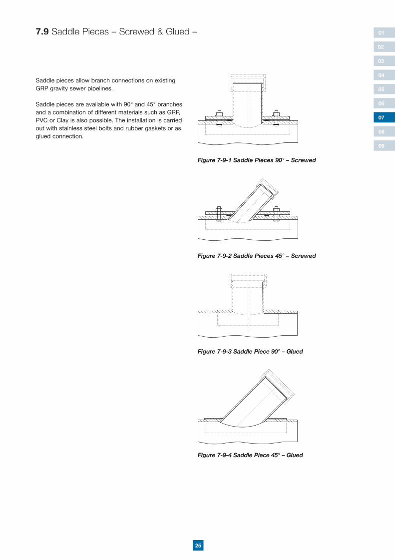
7.9 Saddle Pieces – Screwed & Glued –
Saddle pieces allow branch connections on existing GRP gravity sewer pipelines.
Saddle pieces are available with 90° and 45° branches and a combination of different materials such as GRP, PVC or Clay is also possible. The installation is carried out with stainless steel bolts and rubber gaskets or as glued connection.
Figure 7-9-1 Saddle Pieces 90° – Screwed
Figure 7-9-2 Saddle Pieces 45° – Screwed
Figure 7-9-4 Saddle Piece 45° – Glued
Figure 7-9-3 Saddle Piece 90° – Glued
26
01
02
03
04
05
06
08
09
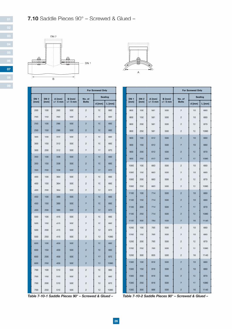
7.10 Saddle Pieces 90° – Screwed & Glued –
For Screwed Only
DN 1 [mm]
DN 2 [mm]
A [mm]+/- 5 mm
B [mm]+/- 5 mm
No. of Bolts
Sealing
d [mm] L [mm]
200 100 260 500 2 10 660
200 150 260 500 2 10 660
250 100 286 500 2 10 660
250 150 286 500 2 10 660
300 100 312 500 2 10 660
300 150 312 500 2 10 660
300 200 312 500 2 12 870
350 100 338 500 2 10 660
350 150 338 500 2 10 660
350 200 338 500 2 12 870
400 100 364 500 2 10 660
400 150 364 500 2 10 660
400 200 364 500 2 12 870
450 100 389 500 2 10 660
450 150 389 500 2 10 660
450 200 389 500 2 12 870
500 100 415 500 2 10 660
500 150 415 500 2 10 660
500 200 415 500 2 12 870
500 250 415 500 2 12 1080
600 100 459 500 2 10 660
600 150 459 500 2 10 660
600 200 459 500 2 12 870
600 250 459 500 2 12 1080
700 100 510 500 2 10 660
700 150 510 500 2 10 660
700 200 510 500 2 12 870
700 250 510 500 2 12 1080
For Screwed Only
DN 1 [mm]
DN 2 [mm]
A [mm]+/- 5 mm
B [mm]+/- 5 mm
No. of Bolts
Sealing
d [mm] L [mm]
800 100 561 500 2 10 660
800 150 561 500 2 10 660
800 200 561 500 2 12 870
800 250 561 500 2 12 1080
900 100 612 500 2 10 660
900 150 612 500 2 10 660
900 200 612 500 2 12 870
900 250 612 500 2 12 1080
1000 100 663 500 2 10 660
1000 150 663 500 2 10 660
1000 200 663 500 2 12 870
1000 250 663 500 2 12 1080
1100 100 714 500 2 10 660
1100 150 714 500 2 10 660
1100 200 714 500 2 12 870
1100 250 714 500 2 12 1080
1100 300 784 500 2 16 1140
1200 100 765 500 2 10 660
1200 150 765 500 2 10 660
1200 200 765 500 2 12 870
1200 250 765 500 2 12 1080
1200 300 835 500 2 16 1140
1300 100 816 500 2 10 660
1300 150 816 500 2 10 660
1300 200 816 500 2 12 870
1300 250 816 500 2 12 1080
1300 300 886 500 2 16 1140
Table 7-10-1 Saddle Pieces 90° – Screwed & Glued – Table 7-10-2 Saddle Pieces 90° – Screwed & Glued –
A 07
DN 1
DN 2
B
27
01
02
03
04
05
06
08
09
07
For Screwed Only
DN 1 [mm]
DN 2 [mm]
A [mm]+/- 5 mm
B [mm]+/- 5 mm
No. of Bolts
Sealing
d [mm] L [mm]
1400 100 867 500 2 10 660
1400 150 867 500 2 10 660
1400 200 867 500 2 12 870
1400 250 867 500 2 12 1080
1400 300 937 600 2 16 1140
1500 100 918 500 2 10 660
1500 150 918 500 2 10 660
1500 200 918 500 2 12 870
1500 250 918 500 2 12 1080
1500 300 988 600 2 16 1140
1600 100 969 500 2 10 660
1600 150 969 500 2 10 660
1600 200 969 500 2 12 870
1600 250 969 500 2 12 1080
1600 300 1039 600 2 16 1140
1700 100 1020 500 2 10 660
1700 150 1020 500 2 10 660
1700 200 1020 500 2 12 870
1700 250 1020 500 2 12 1080
1700 300 1090 600 2 16 1140
1800 100 1071 500 2 10 660
1800 150 1071 500 2 10 660
1800 200 1071 500 2 12 870
1800 250 1071 500 2 12 1080
1800 300 1141 600 2 16 1140
1900 100 1122 500 2 10 660
1900 150 1122 500 2 10 660
1900 200 1122 500 2 12 870
1900 250 1122 500 2 12 1080
1900 300 1192 600 2 16 1140
For Screwed Only
DN 1 [mm]
DN 2 [mm]
A [mm]+/- 5 mm
B [mm]+/- 5 mm
No. of Bolts
Sealing
d [mm] L [mm]
2000 100 1173 500 2 10 660
2000 150 1173 500 2 10 660
2000 200 1173 500 2 12 870
2000 250 1173 500 2 12 1080
2000 300 1243 600 2 16 1140
2100 100 1224 500 2 10 660
2100 150 1224 500 2 10 660
2100 200 1224 500 2 12 870
2100 250 1224 500 2 12 1080
2100 300 1294 600 2 16 1140
2200 100 1275 500 2 10 660
2200 150 1275 500 2 10 660
2200 200 1275 500 2 12 870
2200 250 1275 500 2 12 1080
2200 300 1345 600 2 16 1140
2300 100 1326 500 2 10 660
2300 150 1326 500 2 10 660
2300 200 1326 500 2 12 870
2300 250 1326 500 2 12 1080
2300 300 1396 600 2 16 1140
2400 100 1377 500 2 10 660
2400 150 1377 500 2 10 660
2400 200 1377 500 2 12 870
2400 250 1377 500 2 12 1080
2400 300 1447 600 2 16 1140
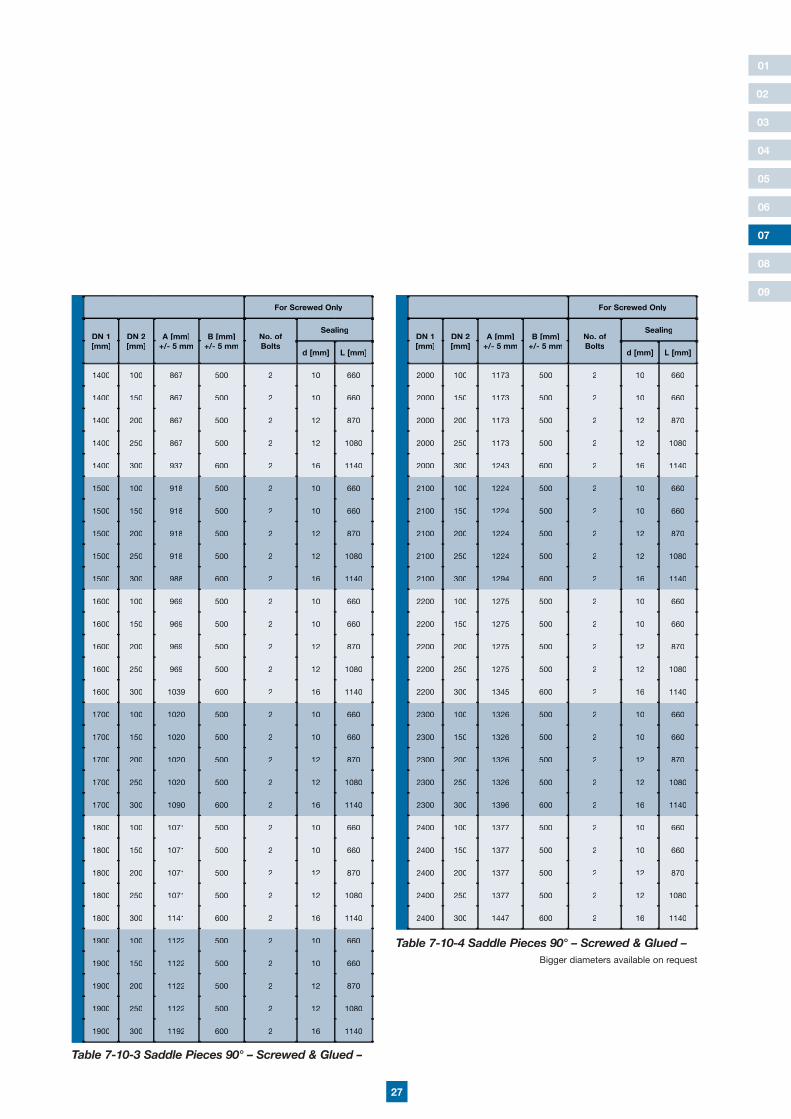
Table 7-10-3 Saddle Pieces 90° – Screwed & Glued –
Table 7-10-4 Saddle Pieces 90° – Screwed & Glued –Bigger diameters available on request
28
01
02
03
04
05
06
08
09
07
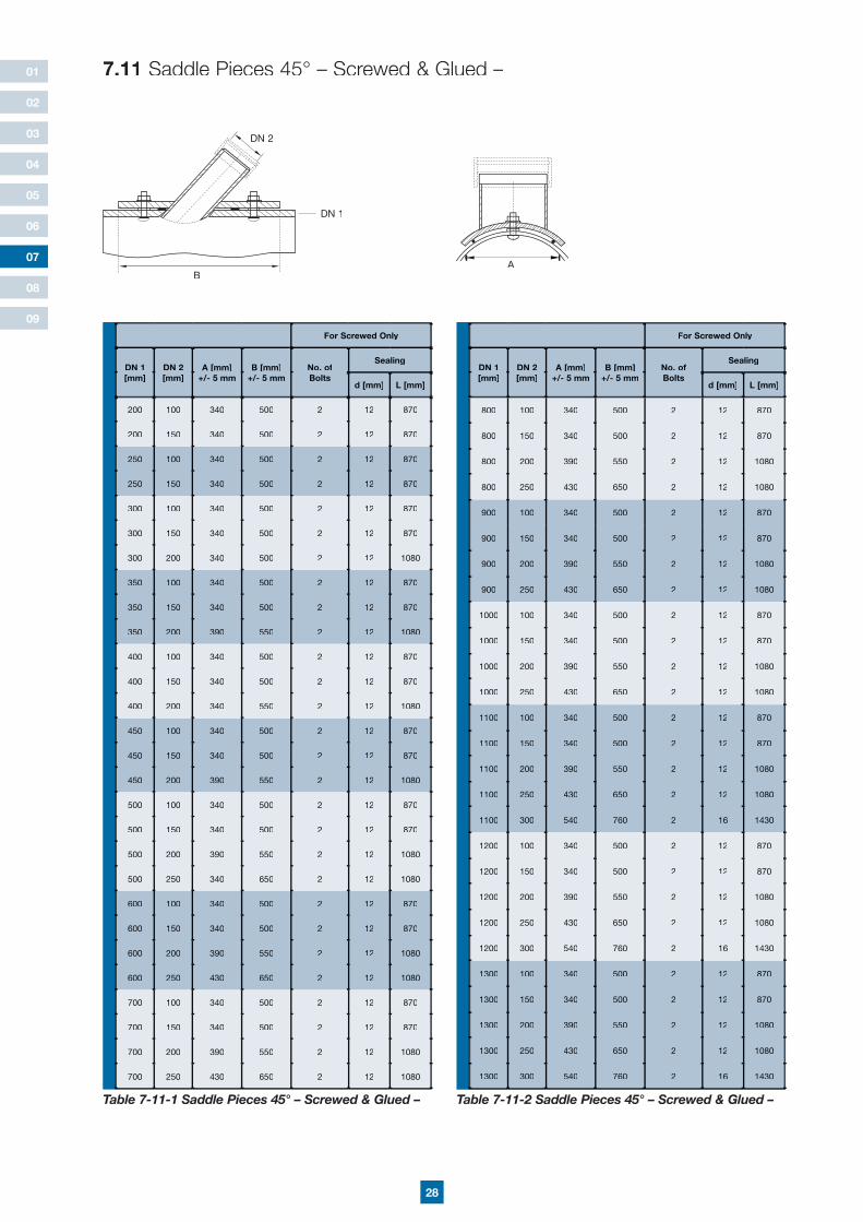
7.11 Saddle Pieces 45° – Screwed & Glued –
For Screwed Only
DN 1 [mm]
DN 2 [mm]
A [mm]+/- 5 mm
B [mm]+/- 5 mm
No. of Bolts
Sealing
d [mm] L [mm]
200 100 340 500 2 12 870
200 150 340 500 2 12 870
250 100 340 500 2 12 870
250 150 340 500 2 12 870
300 100 340 500 2 12 870
300 150 340 500 2 12 870
300 200 340 500 2 12 1080
350 100 340 500 2 12 870
350 150 340 500 2 12 870
350 200 390 550 2 12 1080
400 100 340 500 2 12 870
400 150 340 500 2 12 870
400 200 340 550 2 12 1080
450 100 340 500 2 12 870
450 150 340 500 2 12 870
450 200 390 550 2 12 1080
500 100 340 500 2 12 870
500 150 340 500 2 12 870
500 200 390 550 2 12 1080
500 250 340 650 2 12 1080
600 100 340 500 2 12 870
600 150 340 500 2 12 870
600 200 390 550 2 12 1080
600 250 430 650 2 12 1080
700 100 340 500 2 12 870
700 150 340 500 2 12 870
700 200 390 550 2 12 1080
700 250 430 650 2 12 1080
For Screwed Only
DN 1 [mm]
DN 2 [mm]
A [mm]+/- 5 mm
B [mm]+/- 5 mm
No. of Bolts
Sealing
d [mm] L [mm]
800 100 340 500 2 12 870
800 150 340 500 2 12 870
800 200 390 550 2 12 1080
800 250 430 650 2 12 1080
900 100 340 500 2 12 870
900 150 340 500 2 12 870
900 200 390 550 2 12 1080
900 250 430 650 2 12 1080
1000 100 340 500 2 12 870
1000 150 340 500 2 12 870
1000 200 390 550 2 12 1080
1000 250 430 650 2 12 1080
1100 100 340 500 2 12 870
1100 150 340 500 2 12 870
1100 200 390 550 2 12 1080
1100 250 430 650 2 12 1080
1100 300 540 760 2 16 1430
1200 100 340 500 2 12 870
1200 150 340 500 2 12 870
1200 200 390 550 2 12 1080
1200 250 430 650 2 12 1080
1200 300 540 760 2 16 1430
1300 100 340 500 2 12 870
1300 150 340 500 2 12 870
1300 200 390 550 2 12 1080
1300 250 430 650 2 12 1080
1300 300 540 760 2 16 1430
Table 7-11-1 Saddle Pieces 45° – Screwed & Glued – Table 7-11-2 Saddle Pieces 45° – Screwed & Glued –
A
DN 1
DN 2
B

29
01
02
03
04
05
06
08
09
07
For Screwed Only
DN 1 [mm]
DN 2 [mm]
A [mm]+/- 5 mm
B [mm]+/- 5 mm
No. of Bolts
Sealing
d [mm] L [mm]
1400 100 340 500 2 12 870
1400 150 340 500 2 12 870
1400 200 390 550 2 12 1080
1400 250 430 650 2 12 1080
1400 300 540 760 2 16 1430
1500 100 340 500 2 12 870
1500 150 340 500 2 12 870
1500 200 390 550 2 12 1080
1500 250 430 650 2 12 1080
1500 300 540 760 2 16 1430
1600 100 340 500 2 12 870
1600 150 340 500 2 12 870
1600 200 390 550 2 12 1080
1600 250 430 650 2 12 1080
1600 300 540 760 2 16 1430
1700 100 340 500 2 12 870
1700 150 340 500 2 12 870
1700 200 390 550 2 12 1080
1700 250 430 650 2 12 1080
1700 300 540 760 2 16 1430
1800 100 340 500 2 12 870
1800 150 340 500 2 12 870
1800 200 390 550 2 12 1080
1800 250 430 650 2 12 1080
1800 300 540 760 2 16 1430
1900 100 340 500 2 12 870
1900 150 340 500 2 12 870
1900 200 390 550 2 12 1080
1900 250 430 650 2 12 1080
1900 300 540 760 2 16 1430
For Screwed Only
DN 1 [mm]
DN 2 [mm]
A [mm]+/- 5 mm
B [mm]+/- 5 mm
No. of Bolts
Sealing
d [mm] L [mm]
2000 100 340 500 2 12 870
2000 150 340 500 2 12 870
2000 200 390 550 2 12 1080
2000 250 430 650 2 12 1080
2000 300 540 760 2 16 1430
2100 100 340 500 2 12 870
2100 150 340 500 2 12 870
2100 200 390 550 2 12 1080
2100 250 430 650 2 12 1080
2100 300 540 760 2 16 1430
2200 100 340 500 2 12 870
2200 150 340 500 2 12 870
2200 200 390 550 2 12 1080
2200 250 430 650 2 12 1080
2200 300 540 760 2 16 1430
2300 100 340 500 2 12 870
2300 150 340 500 2 12 870
2300 200 390 550 2 12 1080
2300 250 430 650 2 12 1080
2300 300 540 760 2 16 1430
2400 100 340 500 2 12 870
2400 150 340 500 2 12 870
2400 200 390 550 2 12 1080
2400 250 430 650 2 12 1080
2400 300 540 760 2 16 1430
Table 7-11-3 Saddle Pieces 45° – Screwed & Glued –
Table 7-11-4 Saddle Pieces 45° – Screwed & Glued –
30
01
02
03
04
05
06
08
09
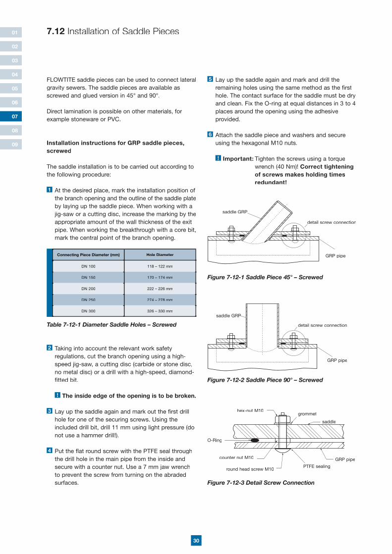
FLOWTITE saddle pieces can be used to connect lateral gravity sewers. The saddle pieces are available as screwed and glued version in 45° and 90°.
Direct lamination is possible on other materials, for example stoneware or PVC.
Installation instructions for GRP saddle pieces, screwed
The saddle installation is to be carried out according to the following procedure:
1 At the desired place, mark the installation position of the branch opening and the outline of the saddle plate by laying up the saddle piece. When working with a jig-saw or a cutting disc, increase the marking by the appropriate amount of the wall thickness of the exit pipe. When working the breakthrough with a core bit, mark the central point of the branch opening.
2 Taking into account the relevant work safety regulations, cut the branch opening using a high- speed jig-saw, a cutting disc (carbide or stone disc, no metal disc) or a drill with a high-speed, diamond- fitted bit.
! The inside edge of the opening is to be broken.
3 Lay up the saddle again and mark out the first drill hole for one of the securing screws. Using the included drill bit, drill 11 mm using light pressure (do not use a hammer drill!).
4 Put the flat round screw with the PTFE seal through the drill hole in the main pipe from the inside and secure with a counter nut. Use a 7 mm jaw wrench to prevent the screw from turning on the abraded surfaces.
Table 7-12-1 Diameter Saddle Holes – Screwed
5 Lay up the saddle again and mark and drill the remaining holes using the same method as the first hole. The contact surface for the saddle must be dry and clean. Fix the O-ring at equal distances in 3 to 4 places around the opening using the adhesive provided.
6 Attach the saddle piece and washers and secure using the hexagonal M10 nuts.
! Important: Tighten the screws using a torque wrench (40 Nm)! Correct tightening of screws makes holding times redundant!
7.12 Installation of Saddle Pieces
07
Figure 7-12-1 Saddle Piece 45° – Screwed
Figure 7-12-2 Saddle Piece 90° – Screwed
Figure 7-12-3 Detail Screw Connection
saddle GRP
saddle GRPsaddle GRP
detail screw connection
detail screw connection
GRP pipe
GRP pipe
hex-nut M10grommet
saddle
GRP pipe
PTFE sealing
counter nut M10
round head screw M10
O-Ring
Connecting Piece Diameter (mm) Hole Diameter
DN 100 118 – 122 mm
DN 150 170 – 174 mm
DN 200 222 – 226 mm
DN 250 274 – 278 mm
DN 300 326 – 330 mm
31
01
02
03
04
05
06
08
09
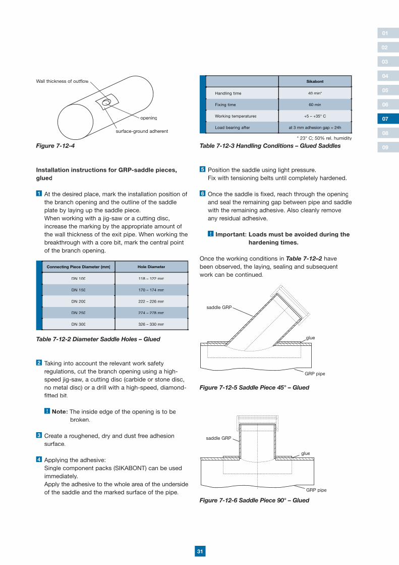
Installation instructions for GRP-saddle pieces, glued
1 At the desired place, mark the installation position of the branch opening and the outline of the saddle plate by laying up the saddle piece. When working with a jig-saw or a cutting disc, increase the marking by the appropriate amount of the wall thickness of the exit pipe. When working the breakthrough with a core bit, mark the central point of the branch opening.
2 Taking into account the relevant work safety regulations, cut the branch opening using a high- speed jig-saw, a cutting disc (carbide or stone disc, no metal disc) or a drill with a high-speed, diamond- fitted bit.
! Note: The inside edge of the opening is to be broken.
3 Create a roughened, dry and dust free adhesion surface.
4 Applying the adhesive: Single component packs (SIKABONT) can be used immediately. Apply the adhesive to the whole area of the underside of the saddle and the marked surface of the pipe.
Connecting Piece Diameter (mm) Hole Diameter
DN 100 118 – 122 mm
DN 150 170 – 174 mm
DN 200 222 – 226 mm
DN 250 274 – 278 mm
DN 300 326 – 330 mm
Table 7-12-2 Diameter Saddle Holes – Glued
07
Sikabont
Handling time 40 min*
Fixing time 60 min
Working temperatures +5 – +35° C
Load bearing after at 3 mm adhesion gap = 24h
Table 7-12-3 Handling Conditions – Glued Saddles* 23° C; 50% rel. humidity
5 Position the saddle using light pressure. Fix with tensioning belts until completely hardened.
6 Once the saddle is fixed, reach through the opening and seal the remaining gap between pipe and saddle with the remaining adhesive. Also cleanly remove any residual adhesive.
! Important: Loads must be avoided during the hardening times.
Once the working conditions in Table 7-12–2 have Table 7-12–2 have Table 7-12–2been observed, the laying, sealing and subsequent work can be continued.
Figure 7-12-5 Saddle Piece 45° – Glued
Figure 7-12-6 Saddle Piece 90° – Glued
saddle GRP
glue
GRP pipe
saddle GRP
glue
GRP pipe
opening
Figure 7-12-4
Wall thickness of outflow
surface-ground adherent
32
01
02
03
04
05
06
08
09
B pyT C pyT 0 pyT 00 pyTA pyT
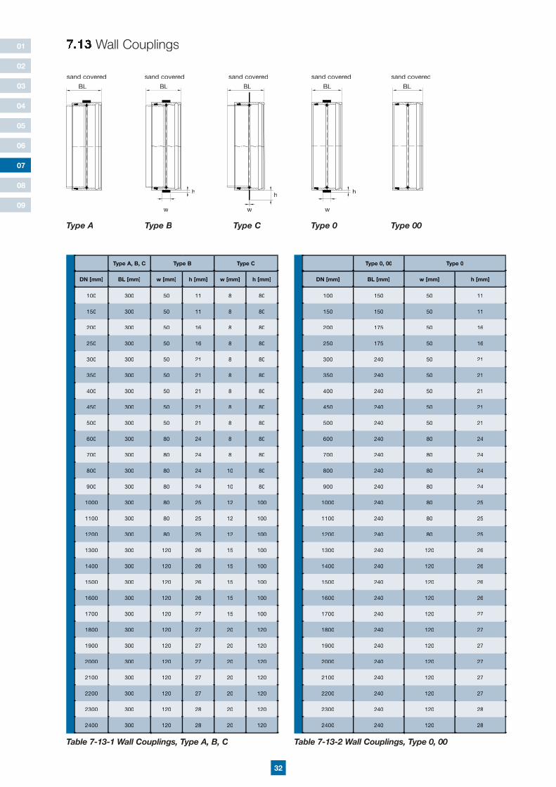
7.13 Wall Couplings
Type A, B, C Type B Type C
DN [mm] BL [mm] w [mm] h [mm] w [mm] h [mm]
100 300 50 11 8 80
150 300 50 11 8 80
200 300 50 16 8 80
250 300 50 16 8 80
300 300 50 21 8 80
350 300 50 21 8 80
400 300 50 21 8 80
450 300 50 21 8 80
500 300 50 21 8 80
600 300 80 24 8 80
700 300 80 24 8 80
800 300 80 24 10 80
900 300 80 24 10 80
1000 300 80 25 12 100
1100 300 80 25 12 100
1200 300 80 25 12 100
1300 300 120 26 15 100
1400 300 120 26 15 100
1500 300 120 26 15 100
1600 300 120 26 15 100
1700 300 120 27 15 100
1800 300 120 27 20 120
1900 300 120 27 20 120
2000 300 120 27 20 120
2100 300 120 27 20 120
2200 300 120 27 20 120
2300 300 120 28 20 120
2400 300 120 28 20 120
Table 7-13-1 Wall Couplings, Type A, B, C
07
Type 0, 00 Type 0
DN [mm] BL [mm] w [mm] h [mm]
100 150 50 11
150 150 50 11
200 175 50 16
250 175 50 16
300 240 50 21
350 240 50 21
400 240 50 21
450 240 50 21
500 240 50 21
600 240 80 24
700 240 80 24
800 240 80 24
900 240 80 24
1000 240 80 25
1100 240 80 25
1200 240 80 25
1300 240 120 26
1400 240 120 26
1500 240 120 26
1600 240 120 26
1700 240 120 27
1800 240 120 27
1900 240 120 27
2000 240 120 27
2100 240 120 27
2200 240 120 27
2300 240 120 28
2400 240 120 28
Table 7-13-2 Wall Couplings, Type 0, 00
B pyT C pyT 0 pyT 00 pyTA pyTType C
w
h
BL
sand covered
B pyT C pyT 0 pyT 00 pyTA pyTType B
w
BL
sand covered
Type 0
h
BL
sand covered
Type 00
BL
sand covered
B pyT C pyT 0 pyT 00 pyTA pyTType A
BL
sand covered
w
h
B pyT C pyT 0 pyT 00 pyTA pyT
33
01
02
03
04
05
06
08
09
07
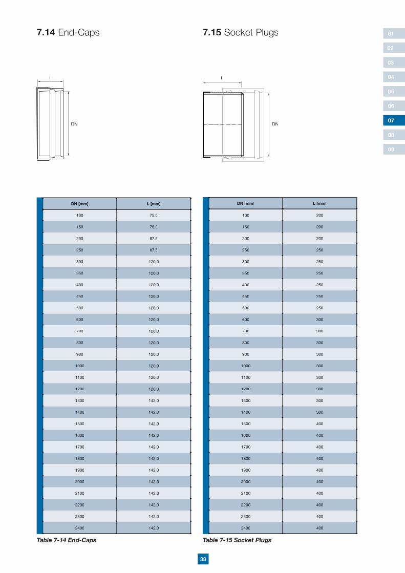
7.14 End-Caps 7.15 Socket Plugs
DN [mm] L [mm]
100 200
150 200
200 200
250 250
300 250
350 250
400 250
450 250
500 250
600 300
700 300
800 300
900 300
1000 300
1100 300
1200 300
1300 300
1400 300
1500 400
1600 400
1700 400
1800 400
1900 400
2000 400
2100 400
2200 400
2300 400
2400 400
Table 7-15 Socket Plugs
DN [mm] L [mm]
100 75,0
150 75,0
200 87,5
250 87,5
300 120,0
350 120,0
400 120,0
450 120,0
500 120,0
600 120,0
700 120,0
800 120,0
900 120,0
1000 120,0
1100 120,0
1200 120,0
1300 142,0
1400 142,0
1500 142,0
1600 142,0
1700 142,0
1800 142,0
1900 142,0
2000 142,0
2100 142,0
2200 142,0
2300 142,0
2400 142,0
Table 7-14 End-Caps
L
DN
L
DN
34
01
02
03
04
05
06
08
09
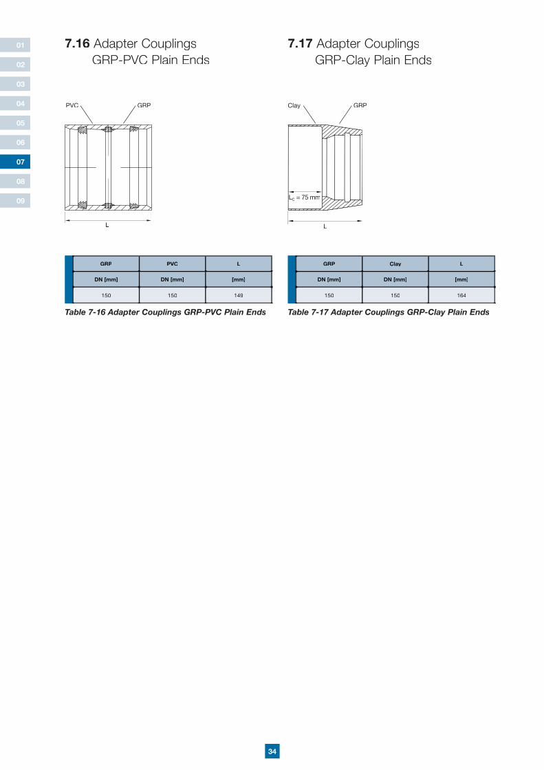
L
PVC GRP
7.16 Adapter Couplings GRP-PVC Plain Ends
7.17 Adapter Couplings GRP-Clay Plain Ends
07
L
LCLCL = 75 mm
Clay GRP
GRP PVC L
DN [mm] DN [mm] [mm]
150 150 149
Table 7-16 Adapter Couplings GRP-PVC Plain Ends
GRP Clay L
DN [mm] DN [mm] [mm]
150 150 164
Table 7-17 Adapter Couplings GRP-Clay Plain Ends
35
01
02
03
04
05
06
08
09
07
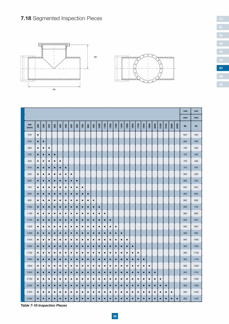
7.18 Segmented Inspection Pieces
min min
mm mm
DN [mm] 20
0
250
300
350
400
450
500
600
700
800
900
1000
1100
1200
1300
1400
1500
1600
1700
1800
1900
2000
2100
2200
2300
2400 BL HL
200 • 600 300
250 • • 600 350
300 • • • 700 350
350 • • • • 700 400
400 • • • • • 700 400
450 • • • • • • 700 500
500 • • • • • • • 800 500
600 • • • • • • • • 800 550
700 • • • • • • • • • 800 600
800 • • • • • • • • • • 800 600
900 • • • • • • • • • • • 800 650
1000 • • • • • • • • • • • • 800 700
1100 • • • • • • • • • • • • • 900 800
1200 • • • • • • • • • • • • • • 900 850
1300 • • • • • • • • • • • • • • • 900 900
1400 • • • • • • • • • • • • • • • • 900 950
1500 • • • • • • • • • • • • • • • • • 900 1000
1600 • • • • • • • • • • • • • • • • • • 900 1050
1700 • • • • • • • • • • • • • • • • • • • 900 1100
1800 • • • • • • • • • • • • • • • • • • • • 900 1150
1900 • • • • • • • • • • • • • • • • • • • • • 900 1200
2000 • • • • • • • • • • • • • • • • • • • • • • 900 1250
2100 • • • • • • • • • • • • • • • • • • • • • • • 900 1300
2200 • • • • • • • • • • • • • • • • • • • • • • • • 900 1350
2300 • • • • • • • • • • • • • • • • • • • • • • • • • 900 1400
2400 • • • • • • • • • • • • • • • • • • • • • • • • • • 900 1450
Table 7-18 Inspection Pieces
HL
BL
36
01
02
03
04
05
06
08
09
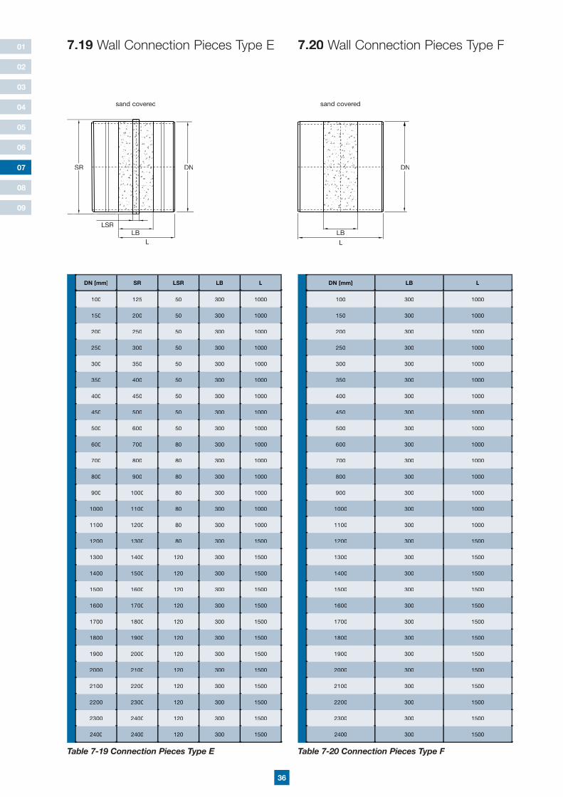
7.19 Wall Connection Pieces Type E 7.20 Wall Connection Pieces Type F
DN [mm] SR LSR LB L
100 125 50 300 1000
150 200 50 300 1000
200 250 50 300 1000
250 300 50 300 1000
300 350 50 300 1000
350 400 50 300 1000
400 450 50 300 1000
450 500 50 300 1000
500 600 50 300 1000
600 700 80 300 1000
700 800 80 300 1000
800 900 80 300 1000
900 1000 80 300 1000
1000 1100 80 300 1000
1100 1200 80 300 1000
1200 1300 80 300 1500
1300 1400 120 300 1500
1400 1500 120 300 1500
1500 1600 120 300 1500
1600 1700 120 300 1500
1700 1800 120 300 1500
1800 1900 120 300 1500
1900 2000 120 300 1500
2000 2100 120 300 1500
2100 2200 120 300 1500
2200 2300 120 300 1500
2300 2400 120 300 1500
2400 2400 120 300 1500
Table 7-19 Connection Pieces Type E
DN [mm] LB L
100 300 1000
150 300 1000
200 300 1000
250 300 1000
300 300 1000
350 300 1000
400 300 1000
450 300 1000
500 300 1000
600 300 1000
700 300 1000
800 300 1000
900 300 1000
1000 300 1000
1100 300 1000
1200 300 1500
1300 300 1500
1400 300 1500
1500 300 1500
1600 300 1500
1700 300 1500
1800 300 1500
1900 300 1500
2000 300 1500
2100 300 1500
2200 300 1500
2300 300 1500
2400 300 1500
Table 7-20 Connection Pieces Type F
07
sand covered sand covered
SR DN
LLB
LSRLB
DN
L
37
01
02
03
04
05
06
08
09
07
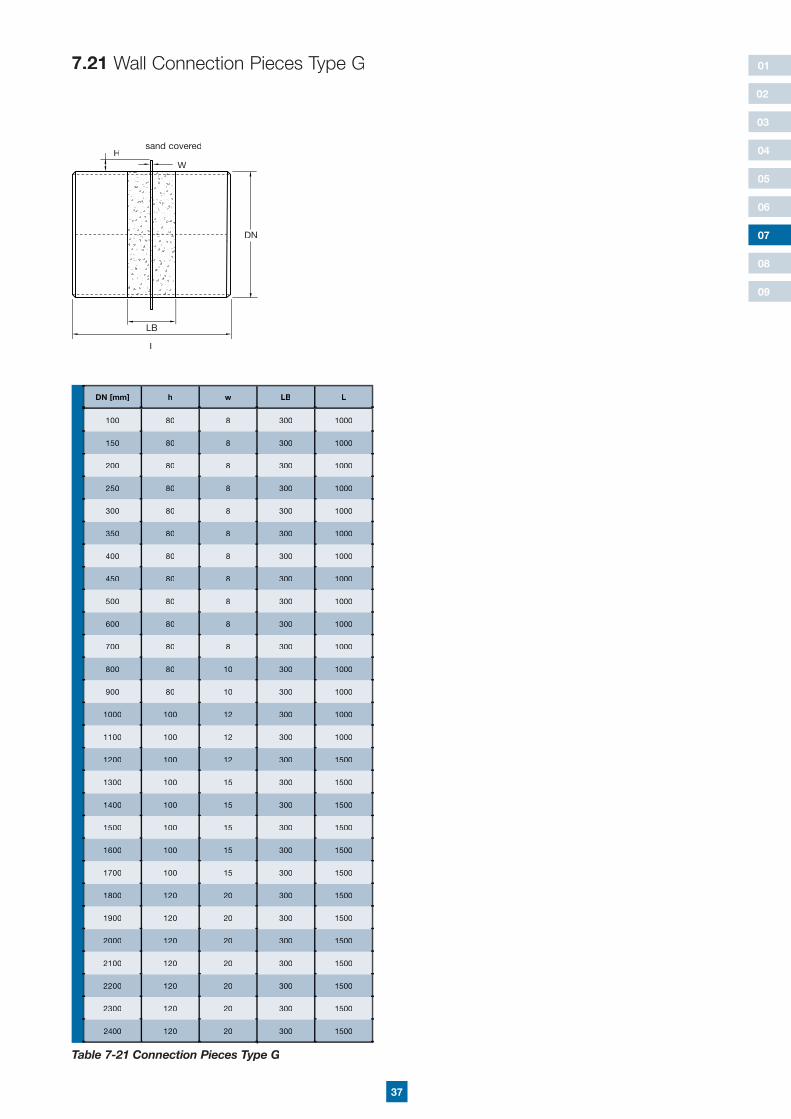
7.21 Wall Connection Pieces Type G
DN [mm] h w LB L
100 80 8 300 1000
150 80 8 300 1000
200 80 8 300 1000
250 80 8 300 1000
300 80 8 300 1000
350 80 8 300 1000
400 80 8 300 1000
450 80 8 300 1000
500 80 8 300 1000
600 80 8 300 1000
700 80 8 300 1000
800 80 10 300 1000
900 80 10 300 1000
1000 100 12 300 1000
1100 100 12 300 1000
1200 100 12 300 1500
1300 100 15 300 1500
1400 100 15 300 1500
1500 100 15 300 1500
1600 100 15 300 1500
1700 100 15 300 1500
1800 120 20 300 1500
1900 120 20 300 1500
2000 120 20 300 1500
2100 120 20 300 1500
2200 120 20 300 1500
2300 120 20 300 1500
2400 120 20 300 1500
Table 7-21 Connection Pieces Type G
sand covered
LB
L
DN
WH
38
01
02
03
04
05
06
08
09
07
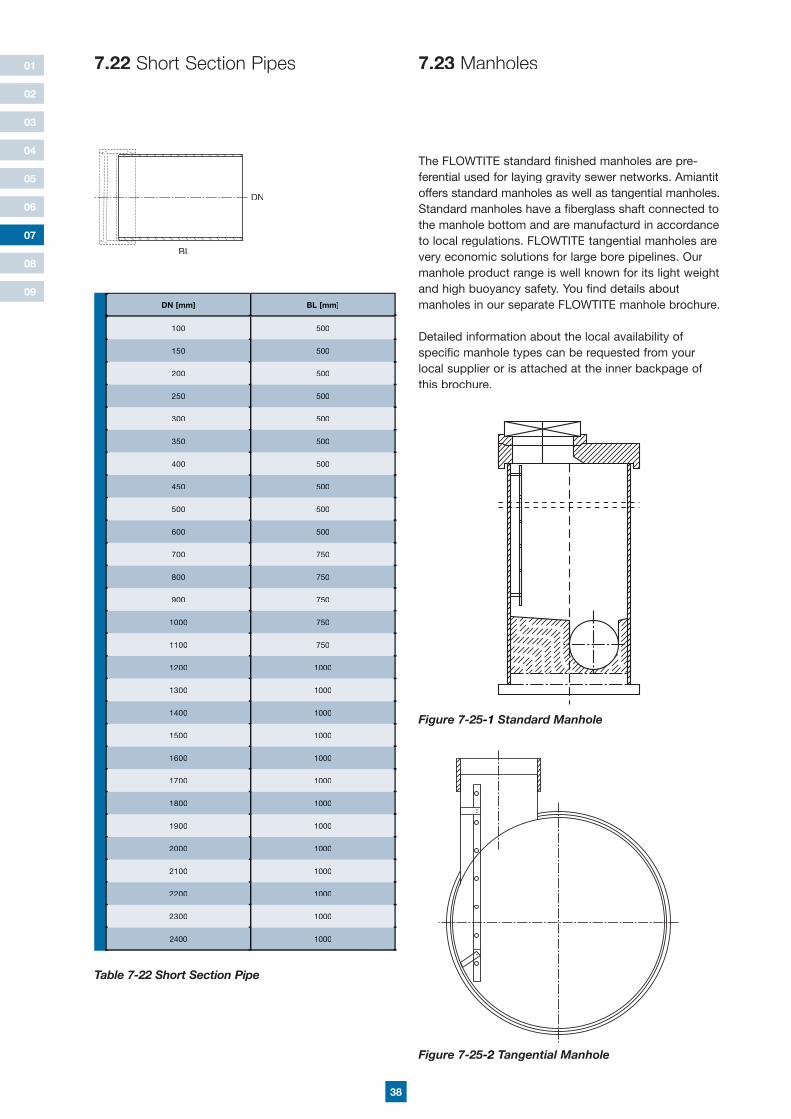
7.22 Short Section Pipes
DN [mm] BL [mm]
100 500
150 500
200 500
250 500
300 500
350 500
400 500
450 500
500 500
600 500
700 750
800 750
900 750
1000 750
1100 750
1200 1000
1300 1000
1400 1000
1500 1000
1600 1000
1700 1000
1800 1000
1900 1000
2000 1000
2100 1000
2200 1000
2300 1000
2400 1000
Table 7-22 Short Section Pipe
The FLOWTITE standard finished manholes are pre-ferential used for laying gravity sewer networks. Amiantit offers standard manholes as well as tangential manholes. Standard manholes have a fiberglass shaft connected to the manhole bottom and are manufacturd in accordance to local regulations. FLOWTITE tangential manholes are very economic solutions for large bore pipelines. Our manhole product range is well known for its light weight and high buoyancy safety. You find details about manholes in our separate FLOWTITE manhole brochure.
Detailed information about the local availability of specific manhole types can be requested from your local supplier or is attached at the inner backpage of this brochure.
Figure 7-25-1 Standard Manhole
7.23 Manholes
Figure 7-25-2 Tangential Manhole
DN
BL

39
01
02
03
04
05
06
07
09
08
8 Local Approvals & Certifications

This handbook is intended as a guide only. All values listed in the product specifications are nominal. Unsatisfactory product results may occur due to environmental fluctuations, variations in operating procedures, or interpolation of data. We highly recommend that any personnel using this data have specialised training and experience in the application of these products and their normal installation and operating conditions. The engineering staff should always be consulted before any of these products are installed to ensure the suitability of the products for their intended purpose and applications. We hereby state that we do not accept any liability, and will not be held liable, for any losses or damage which may result from the installation or use of any products listed in this handbook as we have not determined the degree of care required for product installation or service. We reserve the right to revise this data, as necessary, without notice. We welcome comments regarding this handbook.
FT-S
ewer
V1
06-0
7-E
NG
Distributed by:
Flowtite Technology ASP.O. Box 20593202 SandefjordNorwayTel.: + 47 33 44 92 80Fax: + 47 33 46 26 [email protected]


