Flue Gas Heat Recovery systems (FGHRS): Data requirements and assessment methodology for recognition in SAP (SAP 2009 revision) This report describes the laboratory data requirements, technical specifications and assessment method of a class of flue gas heat recovery systems to enable recognition in the Government’s Standard Assessment Procedure. It supersedes and expands on a procedure developed for passive flue gas heat recovery devices, which are a subset of FGHRS. Prepared for: DEFRA by John Hayton 18 th March 2008 SAP 2009 Revision SAP 2009 brought FGHRS into the main calculation procedure which involved moving the procedure from Appendix Q to Appendix G and moving the technical details in the product database (formerly the boiler database). SAP 2009 introduces the classification of integrated PFGHRD. This revision describes the laboratory data requirements, technical specifications for inclusion in SAP 2009 and SAP 2005; as SAP 2005 will run concurrently for a few years. New sections are added are: 1.1, 3.3 and 5.1. by John Hayton 28 October 2010
Transcript
Flue Gas Heat Recovery systems (FGHRS): Data requirements and assessment methodology for recognition in SAP (SAP 2009 revision) This report describes the laboratory data requirements, technical specifications and assessment method of a class of flue gas heat recovery systems to enable recognition in the Government’s Standard Assessment Procedure.
It supersedes and expands on a procedure developed for passive flue gas heat recovery devices, which are a subset of FGHRS.
Prepared for: DEFRA by John Hayton 18th March 2008 SAP 2009 Revision SAP 2009 brought FGHRS into the main calculation procedure which involved moving the procedure from Appendix Q to Appendix G and moving the technical details in the product database (formerly the boiler database). SAP 2009 introduces the classification of integrated PFGHRD. This revision describes the laboratory data requirements, technical specifications for inclusion in SAP 2009 and SAP 2005; as SAP 2005 will run concurrently for a few years.
New sections are added are: 1.1, 3.3 and 5.1.
by John Hayton
28 October 2010
2 Flue gas heat recovery systems - data requirements and assessment methodology for recognition in SAP (SAP 2009 revision)
2.1 Suitable arrangements .................................................................................................... 7 2.2 Fuel type ......................................................................................................................... 7 2.3 Boiler type ....................................................................................................................... 7
3 Performance data ................................................................................................................... 9 3.1 Thermophysical properties ............................................................................................. 9 3.2 Laboratory data ............................................................................................................... 9
3.2.1 Store charging test ................................................................................................ 11 3.2.2 Store cooling test .................................................................................................. 12 3.2.3 Store discharging test ........................................................................................... 12 3.2.4 Summer hot water test .......................................................................................... 12
4.1 Instant savings .............................................................................................................. 15 4.2 Deferred energy savings ............................................................................................... 16 4.3 Heat saved by reducing wasted hot water ................................................................... 17
4.3.1 Instant reductions in wasted lukewarm water ...................................................... 18 4.3.2 Deferred reductions in wasted lukewarm water ................................................... 18 4.3.3 Total reduction is wasted lukewarm water ........................................................... 18
4.4 Total savings ................................................................................................................. 19 4.4.1 Combi boilers without a keep-hot facility .............................................................. 19 4.4.2 Combi boilers with keep-hot facility ...................................................................... 19 4.4.3 System without a heat store ................................................................................. 20
4.5 Regular boiler systems ................................................................................................. 20 4.5.1 Instant savings ...................................................................................................... 20 4.5.2 Deferred savings ................................................................................................... 20 4.5.3 Energy savings in wasted hot water reduction ..................................................... 21 4.5.4 Total savings ......................................................................................................... 21
5 Application to SAP ................................................................................................................ 22 5.1 SAP 2009 Update ......................................................................................................... 22 5.2 Keep-hot options ........................................................................................................... 23 5.3 Storage options ............................................................................................................. 24
5.3.1 Energy content of the hot water ............................................................................ 25 5.3.2 Cylinder heat loss, combi loss and primary pipe heat loss .................................. 27
5.4 Combining adjustments by boiler types ........................................................................ 27 5.5 FGHRS without heat store ............................................................................................ 27 5.6 Future configurations .................................................................................................... 28
6 Heat store model details ....................................................................................................... 29 6.1 Rate of heat transfer during cooling, charging or discharging ..................................... 30
6.1.1 Rate of cooling ...................................................................................................... 30 6.1.2 Rate of charging .................................................................................................... 30 6.1.3 Rate of discharging ............................................................................................... 30
Flue gas heat recovery systems (FGHRS) are designed to recover heat in the flue gases discharged from a boiler. They use the cold temperature of the domestic cold water supply to recover extra heat that is not extracted by the boiler. The amount of heat that can be extracted by a boiler is usually limited by the temperature of the water in the central heating system.
The potential savings depend critically on the interaction between water heating and central heating service; which vary considerably with dwelling and so a simple percentage of energy savings does not apply.
They can recover heat is two principle ways:
a) Instantly – Recovered heat is immediately used to pre-heat to the domestic water supply before it enters the boiler or external hot water cylinder.
b) Deferred – Heat recovered during space heating production is stored for later use to pre-heat the domestic water supply before it enters the boiler or external hot water cylinder the next time hot water is required.
A methodology for a similar, but not identical, family of devices categorised as passive flue gas heat recovery devices (PFGHRD) has been reported (ref 1). This involved recognition of a PFGHRD in conjunction with a limited range of boiler types as specified and tested. An extension of the method to allow recognition of a PFGHRD with a wider range of fuel and boiler types was documented later (ref 2).
FGHRS can differ because:
• they may not be passive, in that, they may consume electricity
• they are systems (not devices) consisting of separate individual components that are not contained within single package when installed.
This report presents the laboratory test requirements, analytical requirements and methodology to enable the energy performance of flue gas heat recovery systems to be recognised in SAP, Appendix Q. SAP is the UK Government’s energy rating procedure for dwellings and forms the basis of Building Regulation compliance. Appendix Q is a way to achieve recognition of energy saving products without having to wait until a new version of SAP is issued.
It is intended that this new method for FGHRS supersedes the method issued for PFGHRD.
The FGHRS methodology consists of three phases building on that developed for PFGHRD
i) Parameterisation of independent laboratory test and thermophysical data about the system
ii) Using the parameters to simulate the thermal behaviour of the system to generate a large table of savings for a wide range of central heating and water heating requirements.
iii) Reducing the large table, using least squared linear regression analysis, to a manageable number of coefficients for use in SAP, Appendix Q.
5 Flue gas heat recovery systems - data requirements and assessment methodology for recognition in SAP (SAP 2009 revision)
Some FGHRS contain multipurpose cylinders (i.e. cylinders that both store the domestic hot water and are a heat store for the recovered heat) and contain extra circulators or electronic valves. The methodology is not yet applicable to such systems, but may be extended to include these systems with suitable amendments should the need arise.
There are many possible system components and arrangements.
FGHRS must have the following components:
• Boiler by type (combi, regular, primary storage combi, secondary storage, CPSU) and fuel (natural gas, LPG and oil).
• Heat exchanger to capture heat from the boiler flue exhaust to warm the cold water feed of the hot water supply.
• If fitted to a non-condensing boiler specific provision must be made to dispose of the condensate in liquid form.
Optional components include:
Heat store to collect the heat generated during space heating operation: possible types are direct, primary indirect and secondary indirect. Component information required: water volume (for a dual purpose tank, a total and effective volume may need to be specified), insulation thickness and conductivity of the insulation and coil size for indirect stores.
• Hot water coil position (height) in cylinder, heat output and height hot water outlet
• Circulation pump: primary and/or secondary
• Pipework connecting the heat exchanger to store: pipe length, diameter, insulation thickness and thermal conductivity.
• Pipework connecting store hot water feed to cold domestic water feed of the boiler; pipe length, diameter, insulation thickness and thermal conductivity.
• Valves (possibly motor driven) may also be included.
It is important to understand that each arrangement of components and characteristics will affect the potential energy savings. For example, 60 litre and 120 litre cylinders will have different performances due to the amount of recovered heat that can be potentially stored and deferred for later use, i.e. twice as much heat can be stored and deferred for later in a 120 litre system than a 60 litre system.
Therefore a separate analysis is required for each unique arrangement and set of components, including separate laboratory tests plus modelling and regression phases. Once an analysis is complete for particular configurations and characteristics, it may be possible to combine results so that they are applicable for a range of configurations or characteristics.
When fitted to a boiler, the system recovers heat from the flue products to pre-heat the domestic hot water supply. Utilising a heat store within the system, energy recovered during space heating production can also be used to later offset the heat required for providing domestic hot water.
There are three ways the system can save energy:
6 Flue gas heat recovery systems - data requirements and assessment methodology for recognition in SAP (SAP 2009 revision)
• Instant savings - During production of hot water, heat is recovered from the flue products and instantly used to warm the cold water feed.
• Deferred savings - When the boiler is firing for space heating purposes, the system recovers heat from the flue products and stores it. The heat is later transferred to pre-heat the cold water feed of the domestic water.
• Reduced wasted hot water - Instantaneous combination boilers, despite their name, take a little time to provide hot water, mainly because the water and heat exchangers within the boiler require warming before the domestic water can be heated to an acceptable temperature. This means some water may be wasted because it is not warm enough. The system may reduce the amount of rejected lukewarm water. This option is only applicable to combi boiler without a keep hot facility. Storage combi, regular and instant combi boilers with a keep hot provide hot water immediately and so savings via reduced wasted hot water are not appropriate.
1.1 SAP 2009 update (introduction)
SAP 2009 moved the calculation procedure of fghrs from Appendix Q (a temporary add-on requiring a separate workbook that estimated the savings) to the main part of the procedure (describe in appendix G). This required data are stored in Appendix Q workbook to be moved to the FGHRS table of the product characteristic database (PCDB)1; after conversion to monthly coefficients.
SAP 2009 made provision for a new class of PFGHRD; integral PFGHRD. An integral PFGHRD is device that is part of the boiler as made and sold. A non- integral device is one that can be, subject to the usual constraints, fitted to any boiler or is fitted on installation.
A boiler with integral PFGHRD is indicated by a couple of extra records on the boiler table entry in the PCDB. The first extra record indicates the type of PFGHRD to be fitted to the boiler (storage or none) and the second is an optional index that points to an entry in FGHRS table. This FGHRS contains the technical details of the FGHRS fitted to the boiler (eg the regression coefficients).
New sections 3.3 (revised test options) and 5.1 (revised regression conditions) have been added concerning SAP 2009.
1 Previously known as the boiler database; the name has change because the database contains data on other products.
7 Flue gas heat recovery systems - data requirements and assessment methodology for recognition in SAP (SAP 2009 revision)
Flue gas heat recovery systems are not suitable for all types of boiler.
2.1 Suitable arrangements
Adding the system potentially interferes with the air and combustion product flow to and from the boiler and therefore may not be suitable for retrofitting. They are only suitable for appliances where laboratory tests on the combustion/safety performance of the boiler with the system operational have been carried out satisfactorily.
Recovering heat from the flue gases will result in a slightly acidic condensate once the dew point is reached. Condensing boilers are designed to cope with the corrosive condensate and to safely dispose of it in liquid form.
Critically, non-condensing boilers are not designed for prolonged exposure to the condensate and if a system were fitted it could lead to serious damage, reducing the potential operating life of the boilers but also compromising safety. Thus the application is restricted to condensing boilers unless specific provision is made to dispose of the condensate in liquid form.
2.2 Fuel type
When water droplets condense on the surface of a heat exchanger the latent heat is absorbed by the exchanger and does not cool the flue products, thus maintaining the temperature differential - the driving force of heat transfer. Therefore the amount of water vapour in the flue products will influence the effectiveness of the system, and this varies by hydrogen content of the fuel.
As the elemental hydrogen content of natural gas, liquid petroleum gas and heating oil varies, the effectiveness of a system with also vary, therefore:
• separate performance data by fuel is preferred.
In the absence of a separate fuel analysis a conservative estimate for LPG and Oil based on analysis for natural gas may be applied.
2.3 Boiler type
In SAP (Appendix D) boilers are categorised into five main types:
• Instantaneous combi without keep-hot facility
• Instantaneous combi with keep-hot facility
• Regular boiler
• Storage combi
8 Flue gas heat recovery systems - data requirements and assessment methodology for recognition in SAP (SAP 2009 revision)
With instantaneous combi boilers, when the hot water tap is turned on, the boiler fires immediately. For other boiler types the firing of the boiler is buffered from the hot water demand. This means that the energy savings depend on the boiler type and hot water storage arrangements. The test data as described in Section 2 provides the savings for the case of an instantaneous combi without keep-hot facility, and the savings for other cases are detailed in (ref 4 or appendix).
9 Flue gas heat recovery systems - data requirements and assessment methodology for recognition in SAP (SAP 2009 revision)
In order for the energy savings potential to be estimated by the SAP, performance data comprising of laboratory test data and thermophysical properties concerning the system are required. This section presents the performance data required.
3.1 Thermophysical properties
The thermophysical properties of the system required are:
• Weight of heat exchanger(s) in kg
• Volume of water in the heat exchanger(s) in litres (include both primary and secondary water)
• Specific thermal capacity of the heat exchanger(s) material(s) in kJ/kg/K
• Volume of hot water in store in litres
• Specified maximum total length (m) and diameter (mm), insulation conductivity (W/m/K) and thickness (mm) of connecting pipework between store and heat exchanger.
• Specified maximum total length (m) and diameter (mm), insulation conductivity (W/m/K) and thickness (mm) of connecting pipework between store and cold water feed to boiler.
• Specified minimum height between the store’s highest domestic water level and the highest water level in the heat exchanger.
• Properties of the new instantaneous combi boiler (no “keep-hot” facility) used in the tests
o Boiler name and model
o Minimum firing input rate in central heating mode (kW net)
o BED Declared efficiency at full and 30% part load
o Seasonal efficiency (SEDBUK)
3.2 Laboratory data
Four sets of laboratory tests are required to characterise the key properties of the system. All tests are conducted using a new combi boiler without keep-hot facility, having a SEDBUK efficiency of at least 90% for condensing boilers or SEDBUK efficiency of at least 80% for non-condensing boilers.
Any connecting pipes must be at manufacturer’s specified maximum length and maximum diameter and minimum insulation thickness and conductivity.
10 Flue gas heat recovery systems - data requirements and assessment methodology for recognition in SAP (SAP 2009 revision)
The height of the store above the heat exchanger must also be at its minimum height as specified by the manufacturer if water is circulated by gravity (natural convection).
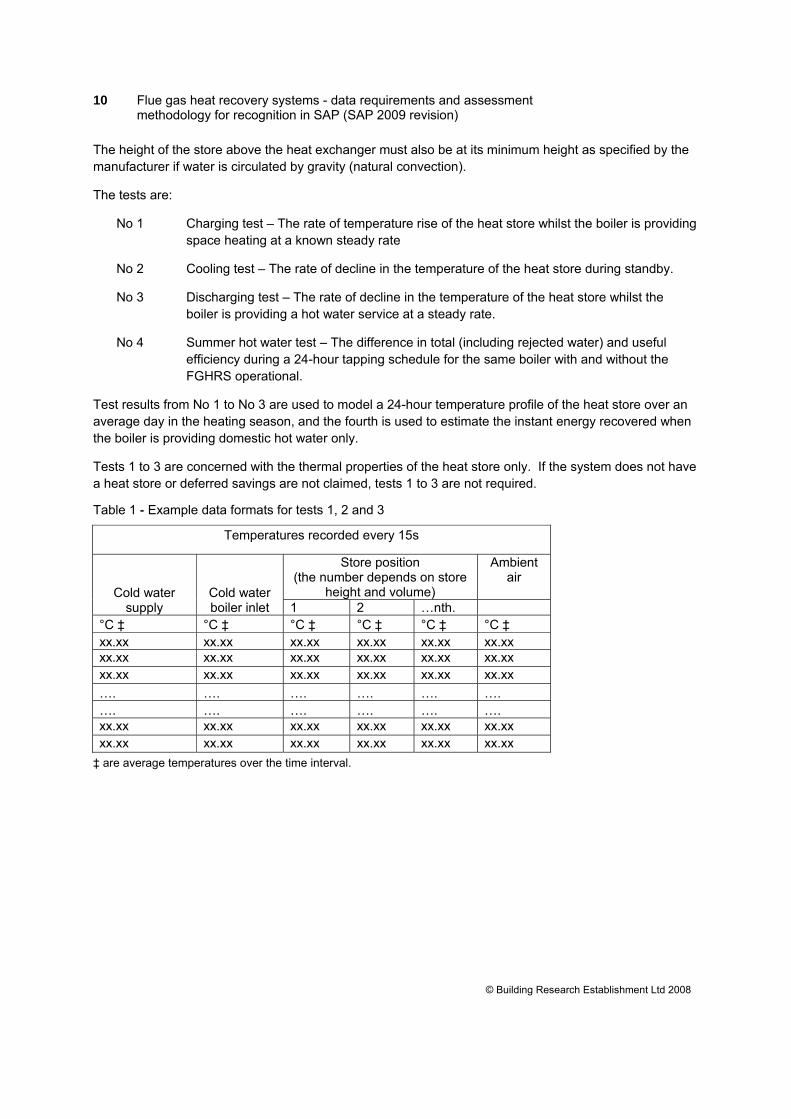
The tests are:
No 1 Charging test – The rate of temperature rise of the heat store whilst the boiler is providing space heating at a known steady rate
No 2 Cooling test – The rate of decline in the temperature of the heat store during standby.
No 3 Discharging test – The rate of decline in the temperature of the heat store whilst the boiler is providing a hot water service at a steady rate.
No 4 Summer hot water test – The difference in total (including rejected water) and useful efficiency during a 24-hour tapping schedule for the same boiler with and without the FGHRS operational.
Test results from No 1 to No 3 are used to model a 24-hour temperature profile of the heat store over an average day in the heating season, and the fourth is used to estimate the instant energy recovered when the boiler is providing domestic hot water only.
Tests 1 to 3 are concerned with the thermal properties of the heat store only. If the system does not have a heat store or deferred savings are not claimed, tests 1 to 3 are not required.
Table 1 - Example data formats for tests 1, 2 and 3
Temperatures recorded every 15s
Cold water supply
Cold water boiler inlet
Store position (the number depends on store
height and volume)
Ambient air
1 2 …nth. °C ‡ °C ‡ °C ‡ °C ‡ °C ‡ °C ‡ xx.xx xx.xx xx.xx xx.xx xx.xx xx.xx xx.xx xx.xx xx.xx xx.xx xx.xx xx.xx xx.xx xx.xx xx.xx xx.xx xx.xx xx.xx …. …. …. …. …. …. …. …. …. …. …. …. xx.xx xx.xx xx.xx xx.xx xx.xx xx.xx xx.xx xx.xx xx.xx xx.xx xx.xx xx.xx
‡ are average temperatures over the time interval.
11 Flue gas heat recovery systems - data requirements and assessment methodology for recognition in SAP (SAP 2009 revision)
† are spot measurements and ‡ are average temperature of the time interval.
The boiler firing rate, fuel temperature and pressure (if gaseous fuel), and gross calorific value (or higher calorific value)2 and carbon dioxide concentration must be recorded every 20 minutes during test 1.
The ambient temperature must not exceed 25°C and generally not vary by more than 2°C.
3.2.1 Store charging test This test is required to establish the warming rate of the store as a function of its temperature under typical central heating conditions.
A system is fitted to a boiler which is left to settle under ambient conditions with fuel and electricity off before commencing the test.
Measurements begin when the system is warmed by circulating primary water through the heating circuit under the following conditions:
• An average primary boiler flow and return temperature of between 48°C and 50°C at 30% of part load of the nominal maximum space heating output; or at the minimum firing rate for central heating if the minimum is higher than 30%.
The temperature of the heat store at “many” locations is measured every 15 seconds until the store temperature reaches its equilibrium temperature. The ambient temperature of the laboratory air surrounding the boiler and system must remain reasonably constant (within 2°C) and be monitored every 15 seconds.
“Many” locations means that temperature sensors are to be located at the top and bottom of the store underneath the insulation on the metal surface and spaced at 100mm intervals vertically if the height of the store is greater than 200mm. The exact position of the sensors should be recorded. If the store is wider than 1m then additional horizontal sensors are to be placed at each side and if wider than 2m spaced at 1m intervals.
2 If a reference fuel (eg G20) is used the stated reference value may be used instead of a measured value.
12 Flue gas heat recovery systems - data requirements and assessment methodology for recognition in SAP (SAP 2009 revision)
An average of 50°C was chosen as this is approximately half-way between the temperatures specified for gas condensing boilers tested at full and 30% part load for the purposes of the Boiler (Efficiency) Directive.
The ambient temperature must not exceed 25°C and generally not vary by more than 2°C.
3.2.2 Store cooling test This test is required to establish the natural cooling down rate of the heat store as function of store average temperature and laboratory temperature.
Firstly the store is pre-heated as described in the charging test No 1.
The boiler is then switched off completely and left off until the average store temperature returns to ambient air temperature (±0.5°C) or for 16 hours which ever is longer.
The laboratory air and store temperature at the many locations (see 4.2.1) are recorded every 15s. The ambient temperature must not exceed 25°C and generally not vary by more than 2°C.
3.2.3 Store discharging test This test is required to establish the cooling down rate of the heat store when drawing a constant amount of hot water.
Firstly the store is pre-heated as described in the charging test No 1.
Then the domestic hot water is drawn from the boiler at a constant rate until the average temperature of the store is within 0.5°C of the ambient temperature. The temperature of the heat store at the many locations and the ambient temperature is recorded every 15 seconds.
A constant rate of 6 litres/min is selected since this is highest rate in (BS EN 13203):2 No 2 schedule and approximately half the maximum rate of many combi boilers
The temperature of the cold feed must be maintained near 10°C (within ±2°C) and recorded every 15s to verify it.
3.2.4 Summer hot water test This is a 24 hour test required to establish the benefits during hot water production.
Tests, with and without the FGHRS are required to follow BS EN13203:2 – No 2 schedule.
Additional measurements are required to confirm any reported energy savings are feasible. These are:
a) The temperature of the preheated domestic water into the boiler, measured at the same frequency as the cold water supply temperature (into the heat exchanger). If any mixing with cold water occurs, the preheated temperature is taken as the temperature after mixing but before it enters the boiler.
b) The temperature of the pre-heated water as it leaves the heat store measured at the same
frequency as the cold water supply.
c) The integrated energy content over 24 hours of water leaving the heat exchanger but before entering the boiler.
Other required detailed results as specified in EN13203:2 are:
13 Flue gas heat recovery systems - data requirements and assessment methodology for recognition in SAP (SAP 2009 revision)
With the introduction of integral PFGHRD in SAP 2009 a number of test options are possible. These are shown in the table 2.
Table 2 SAP 2009 FGHRS tests
Application
Store Cooling Test
Store Charging Test
Store Discharging
Test
Tapping test: EN13203:2 with device
active
Tapping test: EN13203:2 without the
device or with it bypassed
Integral PFGHRD (non-storage)
N/a N/a N/a Required N/a
Integral PFGHRD (storage)
Required Required Required Required N/a
Non-Integral FGHRS or PFGHRD (non-storage)
N/a N/a N/a Required Required
Non-Integral FGHRS or PFGHRD (storage)
Required Required Required Required Required
Integral PFGHRD (non-storage) based on SAP 2005 recognition*
N/a N/a N/a Uses SAP 2005 result N/a
Integral PFGHRD (storage) based on SAP 2005 recognition*
Uses SAP 2005 result
Uses SAP 2005 result
Uses SAP 2005 result
Uses SAP 2005 result N/a
* Existing SAP 2005 results may be used to recognise boilers with an integral PFGHRD (on application to BRE); provided the device is the same as that originally tested and that the boiler is an instantaneous combi boiler without a keep hot facility or other hot water storage (see below)
The results of the tests on integral PFGHRD are limited to the boiler brand and make tested and the results of non-integral PFGHRD may be applied to other boiler types provided the adjustments to the estimated potential savings (see Appendix G (G5 or G6).
15 Flue gas heat recovery systems - data requirements and assessment methodology for recognition in SAP (SAP 2009 revision)
The potential energy savings are assessed separately for the three mechanisms identified earlier.
• Instant savings – these are related to heat recovered from the flue during hot water production only (i.e. these are the savings that would occur if there were no space heating).
• Deferred savings – these are related to heat recovered and stored during space heating production
• Energy saved by reducing the amount of wasted lukewarm water
The section describes the detailed assessment method, firstly for combi boilers (parts 5.1 to 5.4) and how the method can be extended to apply to regular boilers (5.5).
The detailed assessment proved too complicated for direct implementation in SAP. Instead a set of regression equations were derived to estimated savings predicted by the detailed assessment method. These are discussed in part 5, including application to all boiler types.
The system is assumed to have heat exchangers that recover heat from the flue, and transfer it either to a heat store within the system or instantly to the cold water feed of the domestic hot water supply.
4.1 Instant savings
The Instant energy savings are attributable to the heat transferred immediately from the flue products to the cold water feed of the domestic hot water supply. These are estimated from the summer hot water tests with and without the system (see 4.4). If the store is warmed during hot water operation any subsequent recovery of this energy should evident in 24-hour hot water test data.
The main assumption is that instant savings determined by the 24-hour tapping tests are scalable by the daily hot water load of the dwelling being assessed (i.e. hot water load from SAP) divided by the daily hot load during the 24-hour tapping test without the system fitted.
The estimate of the instant heat recovered in a home with a total annual water heating load (Qanndir ) is:
Q = annhw Danndir
Q Kη×
(1)
where
annhwQ is the annual water heating load (kWh per year). In SAP this is estimated from the daily
water usage which is related to heated floor area. Note that this is the required amount before the boiler efficiency is applied and not the heat input required to produce it. It also includes any
16 Flue gas heat recovery systems - data requirements and assessment methodology for recognition in SAP (SAP 2009 revision)
heat required to warm the wasted hot water because it is below an acceptable temperature, or to required by a keep-hot facility.
η is the seasonal efficiency of the boiler
DK is the instant heat recovery fraction for the system determined from:
1 1
11x w x
Dw
x
K η η ηη
η
−= = − (2)
wη and xη is the useful efficiency (i.e excluding heat wasted because the water is not warm
enough) of hot water production during the 24-hour test with and without the system.
4.2 Deferred energy savings
The deferred energy savings occur when the boiler fires for space heating purposes, warming the heat store. The heat is extracted at the next hot-water draw-off.
Any heating of store during production of water is included in the instant energy savings.
To determine the potential deferred energy savings, knowledge of a typical daily temperature profile of the heat store is required. The profile depends on the water heating and central heating load experienced by the heat store. It is impractical to measure in the field, therefore a mathematical model of the heat store which is calibrated using test data from the laboratory is used instead.
The model predicts a 24-hour temperature profile of the store as a function of annual space and water heating demand for every minute of the day, and hence can calculate the drop in store temperature due to the heat being extracted from the store and delivered to the cold water feed. The deferred energy saved is the sum of temperature drops over 24-hours multiplied by the thermal capacity of store and number of days in the heating season.
The thermal capacity is estimated from the specified metal content of the heat exchanger(s) and water content of the system.
The salient features of the model are discussed here with the details described in part 7.
The mathematical model can predict a 24-hour temperature profile of the store for a given heating load and hot water service by accounting for the heat transferred to/from the store when:
• It is cooling (i.e. when there is no demand for heating or hot water )
• It is discharging (i.e. when the boiler is providing domestic hot water)
• It is charging (i.e. when the boiler is providing space heating)
The daily 24 hour profile is for a typical day during the heating season with a tapping profile based on BS EN 13203 No.2 schedule.
The model requires as a function of store temperature and ambient temperature; the rate of change in store temperature when the boiler is on standby, providing water heating and central heating. These
17 Flue gas heat recovery systems - data requirements and assessment methodology for recognition in SAP (SAP 2009 revision)
functions are determined from specifically designed laboratory tests. The model for the 24-hour profile accounts for varying heating and hot water heating requirements by:
• Scaling the rate of cooling measured during the laboratory tests in line with an assumed average room temperature.
• Scaling the rate of warming measured in the charging test in line with average daily space heating load.
• Scaling the rate of discharging measured at 6 litres/min in the discharging test in line with volume rate in the draw-off. The No.2 tapping schedule (EN 13203) is scaled in line with the daily volume specified by changing the duration of the draw-offs.
The model assumes that heating and hot water are not provided at the same time (i.e. hot water priority), although this is not a crucial assumption.
The formula for the deferred heat recovered by the system due to space heating only is (see part 7for its derivation):
1440minute
, discharging13600d
annind s tK N tQ T× ×Δ
= × ∑ & (3)
where
1440minute
, discharging1s tT∑ & is the sum over all the minutes in the day of the rate of temperature
change of the store due to discharging heat into the cold water feed. The rate of change in temperature depends principally on the temperature of the store and the cold water inlet
K is the thermal capacity of the system
dN is the number days in the heating season (243 days)
tΔ is the time resolution of the model (1 minute)
3600 converts from kJ to kWh hours
4.3 Heat saved by reducing wasted hot water
Due to the need to warm the primary water and heat exchanger, an instantaneous combi boiler has a short delay before water is provided at acceptable temperature. This short delay means some water is rejected because it is not warm enough and hence heat is wasted.
It is claimed the flue recovery system may reduce the amount of wasted water in two ways deferred (using heat recovered in the heat store) and instantly.
18 Flue gas heat recovery systems - data requirements and assessment methodology for recognition in SAP (SAP 2009 revision)
4.3.1 Instant reductions in wasted lukewarm water Any reduction in wasted hot water during hot water production will be evident from the 24-hour tapping test.
4.3.2 Deferred reductions in wasted lukewarm water Any heat in the store that can be immediately extracted is likely to reduce the amount of wasted lukewarm water. It is therefore reasonable to assume that the deferred energy saved in the heating season will also lead to a similar reduction in the energy wasted in the lukewarm water, subject to the maximum of the assumed wasted amount in SAP.
4.3.3 Total reduction is wasted lukewarm water The annual heat saved due to a reduction in wasted hot water can be found by summing of the summer instant amounts (1/3rd of the year) and heating season (2/3rd of the year) deferred and instant amounts.
annhwQ is the annual heat demand for hot water including any the combi heat
loss (table 3a SAP 2005)
annindQ is the amount of the deferred energy saved (determined by the heat
store model and function of annual heating and hot water usage) and assumed to offset the heat wasted in rejected water..
Next the assumptions made in SAP needs considering:
1) SAP assumes 6003 kWh per annum (say 400 kWh in the heating season) is wasted because water is below the acceptable temperature. Therefore the potential savings assessed in SAP need restricting to 400 kWh and 200 kWh in the heating season and summer months respectively.
2) SAP assumes that 25% of the heat in the wasted hot water potentially reduces space heating (the so called reduced heating effect). To avoid the need to specify the fraction which is potentially useful to offset space heating, any reduction in wasted hot water in the heating season is reduced by 25% (i.e multiplied by 0.75).
Two further factors must be considered. The first is the efficiency of the boiler. The lower the boiler efficiency, the greater the amount of gas is required to heat the wasted lukewarm water and the greater the amount of gas that can be saved reducing the volume wasted.
Secondly, a correction factor is needed to prevent double counting of some of the energy savings. The benefit of recovering a portion of the heat required to generate the lukewarm water is included in part 5.1.
3 This is scaled down for water volumes of less than 100 litres/day.
19 Flue gas heat recovery systems - data requirements and assessment methodology for recognition in SAP (SAP 2009 revision)
If there is also a reduction in the amount wasted hot water, there is a corresponding reduction in the amount of heat recovered already included in part 5.1. The correction factor applies this reduction.
Putting the above considerations together, the annual estimate of savings due to reducing the amount of wasted hot water is:
200 400
20.753 3
annhw D annhw D annindannred
kWh kWh
Q K Q K QCF CFQη η≤ ≤
× × ××= × + × + (5)
The bounded terms are subject to the constraints noted by the subscript and are introduced because of the assumed wasted amounts in SAP.
η is the seasonal efficiency
(1 )DCF K= − - the correction factor
4.4 Total savings
The estimate of total savings will vary depending whether a boiler has a keep-hot facility or not.
A “keep-hot” facility is fitted to some instantaneous combi boilers to improve the hot water service. In this situation a gas usage of 600 kWh (clock controlled) or 900 kWh (not clock controlled) is applied by SAP to represent the gas required to keep the domestic water hot.
4.4.1 Combi boilers without a keep-hot facility Adding the savings in 4.1, 4.2 and 4.3, the total savings for a system fitted to a boiler without a keep-hot facility
tot200 400
20.75Q =3 3
annhw f annind annhw D annhw D annind
kWh kWh
Q K Q Q K Q K QCF CFη η η η≤ ≤
× × × ××+ + × + × + (6)
For hot water usage of less 100 litres/day, the limits are reduced by a factor of the daily usage divided by 100.
4.4.2 Combi boilers with keep-hot facility If a boiler has a “keep-hot” facility the amount of wasted hot water is taken as zero in SAP (i.e similar to the case of a hot water cylinder, where hot water is generally always immediately available) and therefore the system cannot be credited with reducing the amount of wasted hot water in SAP.
The system can recover a proportion of the heat from the fuel used by the keep-hot facility. This is included in the estimated instant savings (part 5.1) determined from in the 24-hour tapping test data.
The total saving for a system fitted to a combi boiler with a keep-hot facility is:
totQ = annhw D annindQ K Qη η×
+ (7)
20 Flue gas heat recovery systems - data requirements and assessment methodology for recognition in SAP (SAP 2009 revision)
4.4.3 System without a heat store Some simpler systems may not contain a heat store.
The estimated savings for a system without a heat store fitted to combi without a keep-hot is:
tot200 400
20.75Q =3 3
annhw f annhw D annhw D
kWh kWh
Q K Q K Q KCF CFη η η≤ ≤
× × × ××+ × + × (8)
For hot water usage of less than 100 litres/day, the limits are reduced by a factor of daily usage divided by 100.
The estimated savings for a system without a heat store fitted to combi with a keep-hot is facility is:
totQ = annhw fQ Kη×
(9)
4.5 Regular boiler systems
The approach up to part 4.4 relates to instantaneous combi systems, in this section it is extended to regular boiler systems.
The main concern between regular boiler systems and instantaneous combi systems is that regular systems require a separate hot water tank; that buffers the time of the demand for hot water from the time of firing from the boiler.
The other difference that must be considered is that regular boiler systems, provided that the cylinder is kept hot, will provide hot water at the turn of the tap immediately, unlike instantaneous combi systems without a keep-hot that need a little time to warm the primary hot water in the boiler and the water/water heat exchangers.
4.5.1 Instant savings The main assumption is that the instant savings measured by the difference in the 24-hour tapping tests are scalable in line with the annual hot water load of a dwelling (from SAP) divided by the hot water load during the test.
So provided separate 24-hour tapping tests with and without the system fitted to a regular boiler are available, the effect of the different draw-off times and boiler firing times for hot water in a regular boiler system will be included test results
The boiler firing times during 24-hour hot water test will depend on boiler type, cylinder size and type. To keep things simple, a standard indirect cylinder of 117 litres (to BS 1566) connected to boiler with a heat output of between 8 to 16 kW is required during these tests.
4.5.2 Deferred savings These savings are attributable to heat recovered and stored during the provision of space heating, which is later extracted by drawing cold water through the heat store. This is estimated using a heat store model which estimates a daily store temperature by accounting for heat extracted from the store during each hot water draw off, the heat gained when space heating is provided and the rate of cooling during standby.
The same heat store model applies to both combi and regular boilers because:
21 Flue gas heat recovery systems - data requirements and assessment methodology for recognition in SAP (SAP 2009 revision)
• The rate of discharging heat from the store to the cold water feed is determined by the volume flow rate and the temperature of cold water feed through the store. The volume flow rate and duration of each draw-off is fixed by the 24-hour typical tapping schedule and does not vary between combi and regular systems.
• The rate of cooling from the store during standby will not vary between combi and regular systems
• The rate of warming of the store during space heating provision is unlikely to vary between combi and regular boilers as the thermal efficiencies are similar - what is important is the actual space heating requirement.
4.5.3 Energy savings in wasted hot water reduction For regular boilers the amount of wasted lukewarm water is small, as generally the hot water is immediately available. Therefore flue gas heat recovery systems cannot significantly reduce the amount of wasted hot water for regular systems. There may be a small amount of wasted water if the cylinder can not be recharged in time but this has been ignored.
It is thus a reasonable assumption to assume that the system cannot reduce the amount of wasted hot water so these potential savings are zero.
4.5.4 Total savings As there is no scope for system to reduce wasted lukewarm water, the estimated savings of the system attached to a regular boiler can be determined by:
totQ = annhw D annindQ K Qη η×
+ (10)
where
DK is defined in (2)
annhwQ is the annual hot water heating load including losses associated with the cylinder and
primary pipes.
annindQ is defined in (3)
η is the seasonal efficiency of the boiler.
Note this is same as equation (7) (for a combi boiler with a keep hot facility) because combi boiler with a keep-hot facility and a regular boiler both provide immediate hot water.
22 Flue gas heat recovery systems - data requirements and assessment methodology for recognition in SAP (SAP 2009 revision)
Hot water heating as required by dwellings with floor areas of 30m2 to 420m2 in steps of 20m2
Boiler thermal efficiency 91% (gross)
Then the deferred savings are added to the instant savings, and the heat saved because of a reduction in the amount of wasted hot water (which also varies with hot water and heating demand). The totals are tabulated in the form of a two-way lookup table over the range 0 to 80,000 kWh and a total hot requirement of 1935 kWh/yr to 5643 kWh/yr (or floor area of 30 m2 to 420 m2).
As the two-way lookup table is too large to be convenient for SAP, the dataset is reduced by using least-squares linear regression including a logarithmic transformation for the hot water demand variation at six space heating requirement levels currently4: 0, 2000, 10000, 20000, 40000 and 80000 kWh – to be known as the regression equations in the form:
( ln( )) ( )i i hw i hwSaving b a Q c Q= + × + ×
where ai, bi and ci are sets of regression coefficients and hwQ is the energy of the hot water
including the distribution loss (SAP, table 1 col b + col c) or SAP box (39) + (40) – (50)
5.1 SAP 2009 Update
SAP 2009 is a monthly calculation procedure and with FGHRS now part of the main SAP calculations the cautious assumption (from the point of view of potential savings) about boiler efficiency of 91% can be dropped and the monthly hot water efficiency applicable to the boiler brand and model can be used instead. As SAP is monthly a monthly set of coefficients are required. The annual coefficients can not be used as the range of Qhw for which the savings equation is valid will be different in SAP 2005 and SAP 2009.
The opportunity was also taken to remove the 91% efficiency implicit in the SAP 2005 coefficients from the SAP 2009 coefficients as this is now added explicitly in lines 63 and 219 of the SAP 2009 worksheet.
Potential savings are estimated from the model described in part 4 at:
• space heating of 0, 100, 200, 400, 600, 800, 1000, 1200, 1400, 1600, 1800, 2000, 2400, 2800, 3200, 3600, 4000, 8000, 12000, 16000 and 20000 kWh/month.
4 These may change for a particular FGHRS
23 Flue gas heat recovery systems - data requirements and assessment methodology for recognition in SAP (SAP 2009 revision)
• Hot water used by1 to 8 occupants according to SAP 2009 worksheet line 43 in steps of 0.2 occupants.
The modelled results are reduced to six sets of three coefficients at spacing consumption of: 0, 200, 1000, 2000, 4000 and 20,000 kWh per month.
The regression coefficients are only valid for the range of hot water and space heating modelled; which equates to between 80 kWh/month and 309 kWh/month of hot water and 0 to 80,000 kWh per month of space heating. Above these range the savings the savings are limited to the maximum value. Below the minimum hot water values the savings are reduced linearly until they reach zero at zero hot water use.
5.2 Keep-hot options
The keep-hot facility can be controlled by a clock or not, or heated by electricity, burning fuel or both. Each combination of keep-hot option/FGHRS would in principle require a separate dataset as noted above. However, by introducing the fractional savings ( fK ) into the dataset, the number of datasets
reduces to one.
The fractional saving due to the system for summer hot water is:
'
'1 xf
w
K ηη
= − (11)
'wη and '
xη is the measured total (not useful) efficiency of hot water production during the 24-hour
summer water test with and without the system fitted to combi boiler without a keep-hot facility.
Here unlike, equation (2) the efficiencies are total and not useful so must contain the energy of any rejected water because it is too cool. It is total efficiency because this figure is used to estimate the savings for other boiler types and cannot include the benefit from a reduction in the amount of wasted hot water implicit in the useful efficiencies.
The savings for FGHRS (in kWh/yr ) with a keep-hot facility are adjusted by:
[(0.5 x ( )] / 0.91f kp keK Q Q+ × − (12)
where
keQ is the annual electricity consumed by the keep-hot facility in kWh, if any (see SAP Table 4f).
If the keep-hot facility is fired solely by burning fuel 0eK =
kpQ is the “combi loss” for the boiler in question for example 600 kWh for timed keep-hot facility.
0.91 is the efficiency of the boiler assumed in the regression equations
0.5 is introduced because the heat recovered will be reduced by about half when the boiler is firing to warm the keep-hot facility (see similar argument in 5.2).
24 Flue gas heat recovery systems - data requirements and assessment methodology for recognition in SAP (SAP 2009 revision)
Hot water storage adds a time lag between hot water demand and fuel demand.
Restricting our attention to hot water production (space heating is already dealt with already), there are times when:
Hot water is running and the boiler is firing – condition (a)
Hot water is not running and boiler is firing – condition (b)
Hot water is running and the boiler not firing – condition (c)
It is important to consider the three conditions separately because the energy transfer differs for each condition.
Each FGHRS consists of three heat exchange paths or mechanisms:
1) Flue gas to the cold water feed - condition (a) applies
2) Flue gas to the heat store in FGHRS – condition (b) applies
3) Heat store in FGHRS to the cold water feed – condition (c) applies
For instantaneous boilers in hot water mode heat transfer mechanism (1) applies. The summer hot water tests with an instantaneous boiler results are used to estimate the fraction of heat transferred during condition (a), which will occur for at a typical temperature differential of say, 55 K, for a flue gas temperature of 65°C and cold water feed of 10°C.
For storage combis and regular boilers with a separate hot water cylinder mechanisms (1) and (2) apply.
The driving temperature differential for mechanism (2) is typically 27.5 K for a FGHRS temperature of say, the mean of its hottest (65°C) and coldest (10°C) minus the cold water feed temperature (10°C). The amount of heat transferred to FGHRS via mechanism (2) will therefore be approximately, 27.5/55 = 0.5 times of that during mechanism (2). The assumes the heat transfer area is the same, which in the absence of data is the most likely case.
Mechanism (3) transfers energy from the heat store to cold water feed whilst the hot water is running and the boiler is not firing. Assuming that most of the energy from the FGHRS is extracted, this rate of transfer is not an issue; what matters is how much energy is stored in the first place under mechanism (2).
The assumption just noted is reasonable because the FGHRS very rapidly extracts heat when cold water is passed through it, so it is likely that the only energy not recovered will be from the last hot water draw-off at night and in the morning if the dwelling is unoccupied during the daytime. And even here some will be saved until the next hot water draw-off. The bit of energy not recovered is very small, for example, at most 10% of the energy from the last the hot water draw-off can be wasted. The average draw-off volume is around 5 litres warmed by 50K in a total of 100 litres warmed by 50K in the BS EN13203 number 2 schedule. The amount wasted would be around 10% of 5 in 100, which is 0.5%. For two ‘last’ draws-offs a day this gives 1% but around half of this recovered, suggesting only 0.5% is lost. The energy content of the heated water and losses associated with storing it will be considered separately to determine the relative occurrence of condition (a) or (b). This information can then be used to adjust the savings for instantaneous with keep-hot facility so it is applicable to storage combi and regular boilers.
25 Flue gas heat recovery systems - data requirements and assessment methodology for recognition in SAP (SAP 2009 revision)
5.3.1 Energy content of the hot water This part derives a formula to estimate how often condition (a) and by subtraction from 1 how often condition (b) applies because of the energy requirement of the hot water only.
How often condition (a) occurs depending on, amongst others, cylinder type, cylinder volume, volume of hot water used and cylinder and primary pipe heat loss.
BS EN 13203, number 2 schedule, specifies 100 litres warmed by 50K with the two largest volumes of 40 litres warmed by 30K; one early in the morning and the other late at night. In terms of energy, each equate to a 24 litres warmed by 50K. The third highest volume is 14 litres warmed by 45K (or 12.6 litres warmed by 50K). The rest are small volumes of 6 litres or less.
Thermostats on cylinders are usually placed a third the way up a cylinder. When hot water is run, cold water enters bottom of the cylinder forming a boundary layer of cold water (a cold front). The cold front rises and when it hits the thermostat, it tells the boiler to fire. When the cold front hits the thermostat about a third of the water has been drawn. Therefore, it is deduced that boiler will only start to fire after around a third of the hot water has been used. Condition (a) will apply after many smaller draw-offs in quick succession, but only during of last run so for a short time.
Typical replenishment rates are 12.4 to 15.8 kW for 100 to 300 litres. The largest water draw-off rate is 6 litres/min warmed by 30K, or 12.5kW, making the replenishment rate similar to or greater than the water flow rate.
Condition (a) will mostly arise for large draw-offs only. Assuming that the two largest hot water draw-offs, on average, start when the cold front is midway between the bottom and thermostat, the boiler will start firing when a sixth of hot water in the cylinder has been used. If the replenishment rate is at least equal to of energy in the running in water, the fraction of the time the boiler spends firing whilst hot water is flowing - condition (a) - is:
2 (24 ) 486100 100 300
cyl
cyln
VV
K× −
= = −
2 is for two large draw-offs of 24 litres warmed by 50K and cylV is volume of cylinder.
For larger cylinders, higher than (6 x 24) litres, the largest draw-off can be made without the cold front reaching the thermostat. So above 144 litres it is reasonable to conclude that the boiler will infrequently fire when hot water is running, so 0.nK =
For small cylinders the third highest draw-off will add to the time when the boiler is firing and hot water is running. This occurs when the volume of cylinder divided by 6 is less than 12.6 litres; the equivalent volume of third highest draw-off. Or stated another way, when the cylinder is 6 x 12.6 litres, say 75 litres for simplicity, the time spend when firing and running water will be 23%. So at 75 litres the nK = 0.23.
For instantaneous combis that the boiler is always firing when hot water is run, so nK =1. A definition in
SAP is that storage combi must have at least 15 litres of hot water. So for consistency an instantaneous combi and 15 litre storage combi must have then same value of nK = 1.
Introducing two constants a and b (unknowns to be determined) for nK between 15 and 75 litres then:
26 Flue gas heat recovery systems - data requirements and assessment methodology for recognition in SAP (SAP 2009 revision)
To ensure consistency at 15 litres ( nK =1) litres and 75 litres ( nK =0.23) gives:
1.1925 (0.77 60)n cylK V= − × ÷ (13)
If the cylinder is a primary type, the cylinder can store more heat, in fact 65K/50K = 1.3 times as much, so by defining an effective volume as kV
If a primary cylinder set 1.3k cylV V= × (14)
If a secondary cylinder set k cylV V= (15)
In summary, the fraction of time the boiler is firing to provide the energy in the hot water and hot water is flowing is: nK such that:
For 144 kV > 0nK =
For 75 and 144 k kV V≥ ≤ 0.48 ( 300)n kK V= − ÷
For 15 and <75 k kV V≥ 1.1925 (0.77 60)n kK V= − × ÷
For 15kV < 1nK =
(16)
The savings for the combi estimated by the lookup table include the heat recovered during hot water production as:
/n f hwK K Q η+ × × (17)
( 1nK = , hwQ is col (b) plus (c) of SAP table 1, or box (39) plus (40) minus (50))
The adjustment to the savings for storage combi is to subtract the amount when condition (a) does not apply, which is:
0.5 (1 ) /n f hwK K Q η− × − × × (18)
(0.5 is due to mechanism (2) being about half of effective of mechanism (1) see above)
For regular boilers with separate water heating times the situation is more complicated and might be zero. However as the value of Kn is small for most regular boilers (with cylinders 100 to 144 litres) and zero for cylinders bigger than 144 litres, the difference in savings between assuming Kn = 0 or the calculated Kn in (18) is small. For example, if Kf is 10% and for a 120 litre cylinder, it would be 0.08 x 0.10 /0.91 = 0.9%. As the difference is small the extra complication of separate heating times is not worth introducing.
27 Flue gas heat recovery systems - data requirements and assessment methodology for recognition in SAP (SAP 2009 revision)
5.3.2 Cylinder heat loss, combi loss and primary pipe heat loss The boiler will also fire when the cylinder has emitted sufficient heat to cool water below the thermostat setting. It can reasonably be assumed that energy required to keep the cylinder warm occurs under condition (b), so an adjustment due cylinder and primary pipe losses is:
0.5 ( ) /f acylK Q η+ × × (19)
where is acylQ heat requirement associated with the cylinder, primary pipe or combi losses SAP
box (47) + (48) + (49)
5.4 Combining adjustments by boiler types
The adjustments to savings are based on the savings tables for the combi with a keep-hot facility only because like storage systems there is no scope for reducing the amount of wasted hot water because it does not reach a minimum acceptable temperature.
For small volume, 15 litres to 55 litres, the amount assigned in due to waste water is gradually phased out. The phasing is too complicated to be considered for FGHRS, so ignored. For the smallest volumes there will be slight underestimate in the savings of about 20 kWh/yr (i.e. half of 7% of 600 kWh/yr).
Combining (12), (18) and (19), the saving adjustment for a storage combi, regular or instantaneous boiler with a keep hot facility is:
{(0.5 ( )) [0.5 (1 ) ]} /acyl ke n hw fQ Q K Q K η× − − × − × × (20)
keQ is the annual electricity consumed by the keep-hot facility in kWh, if any (see SAP Table 4f).
acylQ is the sum of the cylinder heat loss, combi loss (SAP table 3a) or primary pipe heat loss
(SAP table 3) or SAP box (47) + (48) + (49)
hwQ is the energy of the hot water including the distribution loss (SAP, table 1 col b + col c) or
SAP box (39) + (40) – (50)
nK is defined in (16) which requires (13) and (14).
η is the efficiency of boiler implicit in the regression coefficients ( = 0.91)
These are slightly conservative estimates because they ignoring the small timing by chance that water is flowing whilst the boiler is warming cylinder to offset the cylinder heat loss, the primary pipes, the keep-hot facility or small water run-offs.
For an instantaneous boiler without a keep-hot facility use the savings table unadjusted.
5.5 FGHRS without heat store
FGHRS without a heat store cannot recover heat during space heating mode to later partly offset water heating requirement so there are no deferred savings. There are also no savings possible with hot water production when the boiler firing and water draw-off do not coincide, so there are savings associated with
28 Flue gas heat recovery systems - data requirements and assessment methodology for recognition in SAP (SAP 2009 revision)
primary pipe, combi or cylinder heat losses. Thus, the savings (not the adjustment to the savings) are only those that occur when hot water production coincides with boiler firing which can be estimated from:
0.91n hw fsaving K Q K= × × ÷ (21)
with the terms as defined in (20) above.
5.6 Future configurations
This section describes the principles of the approach necessary to include possible future systems. Details are not specified here as this was not included in this phase of the work programme.
5.6.1 Circulators or motorised valves If circulators or motorised valves or other electrically powered components are part of the FGHRS, their power consumption must also be monitored during the tests.
An estimate of the annual consumption based on the laboratory data will be determined and added as an electrical consumption in the appropriate Appendix Q SAP box.
5.6.2 Multipurpose heat storage These vessels store both the domestic hot water and the deferred heat recovered by the FGHRS. This can be achieved by a dual coil cylinder, for example. The top coil is connected to the boiler’s primary circuit and the lower coil is supplied by the recovered deferred heat.
If a multipurpose vessel is heated the upper volume is generally kept warm by the boiler so hot water is immediately available. When heat is recovered, it heats the lower volume, which would be otherwise cold. Effectively the cylinder is divided thermally. The upper volume is like a conventional cylinder and stores domestic hot water. The lower part acts as a heat store for FGHRS.
It is anticipated that tests will need to be modified to account for the characteristics of multipurpose stores by specifying a temperature of the upper volume during the test. It is also anticipated that the modelling phase will need to be modified to include only the effective volume of the FGHRS.
5.6.3 Boilers types
Some special features of some FGHRS configurations may only work with a particular boiler type (eg regular). If this proves to be the case, the analysis will be restricted to this boiler type.
29 Flue gas heat recovery systems - data requirements and assessment methodology for recognition in SAP (SAP 2009 revision)
This section gives the details of the heat store model. A discussion of the salient features is given in part 4.3.
A mathematical model of the heat store is used to predict a typical 24 day temperature profile, which in turn with knowledge of the thermal capacity is used to estimate the deferred heat recovered by the system.
Figure 1 : Heat flows within heat store model
Consider the energy transported to and from the store in a small time interval, Δt, due to three processes cooling, charging or discharging, then the energy of the store (a function of store temperature), ,s t tQ +Δ , at
time t+Δt, is related to the energy content, ,s tQ at time t, by the following:
, , , , , , ,( ) ( ) ( )s t t s t k t s a h t s a c t sQ Q t Q T T t Q T T t Q T+Δ = + Δ × + Δ × + Δ ×& & & (22)
, ,( )k t s aQ T T& is the rate of cooling from the heat store at time t in standby mode which is a
function of the store temperature, sT , and the ambient laboratory temperature,. aT
, ( )c t sQ T& is the rate of heat when charging, that the rate of heat transferred to the store when
providing space heating and is dependent on the temperature of flue products, cold water feed heat store.
, ,( )h t s aQ T T& is the rate of discharging, that is the rate of heat transferred to the cold water feed
from the heat store under a given steady hot water demand.
The right hand terms of equation 1 are specified at time t, so provided the store conditions are known then the store temperature at small time later can be computed.
Discharging - Heat extracted from store during hot water draw-off
Cooling - Heat loss from store through casing
Heat store temperature rises or falls depending heat cooling rate, charging or discharging rate
Charging - Heat recovered to store during space heating operation (charging rate)
30 Flue gas heat recovery systems - data requirements and assessment methodology for recognition in SAP (SAP 2009 revision)
The principle of the method is to solve the equation 1 for store temperature over each 1440 minutes (24 hours) with an imposed daily hot water tapping profile and central heating demand schedule.
Once solved the equation is solved for all time, t, in a day the term , ,( )h t s at Q T TΔ × & is summed over the
day and multiplied by the thermal capacity of the store to calculate the amount of energy transferred from the store to cold water feed.
6.1 Rate of heat transfer during cooling, charging or discharging
To solve (22), the three rates of heat transfer from/to the store as a function of store and ambient temperature must be established. These are established using the laboratory data from the cooling, charging and discharging tests as follows.
6.1.1 Rate of cooling Applying equation (22) to cooling test (standby test) gives:
, , , ,( ) 0 0s t t s t k t s aQ Q t Q T T+Δ = + Δ × + +&
Let K be the heat capacity of the store, then
, , , ,( ) ( )s t t s t k t s aK T K T t Q T T+Δ× = × + Δ × &
Rearranging gives:
, , ,( )k t s a k tQ T T K T= ×& & (23)
where ,k tT& is the rate of change in store temperature during the cooling test.
6.1.2 Rate of charging Applying equation (22) to the charging test gives:
, , , ,( ) 0 ( )s t k t s a c t sK T t Q T T t Q T×Δ = Δ × + + Δ ×& &
Rearranging the above and making use of (14) gives
, ,,
chargingcooling
( ) s t s tc t s
K T K TQ T
t t×Δ ×Δ⎡ ⎤ ⎡ ⎤
= −⎢ ⎥ ⎢ ⎥Δ Δ⎣ ⎦ ⎣ ⎦&
(24)
The change in temperature in the square brackets is during the test indicated by the subscript.
Therefore, , ( )c t sQ T& can be determined by the heat capacity of the store and store temperature profile
during the cooling and charging test.
6.1.3 Rate of discharging During the discharging (constant hot water draw-off) test equation 22 becomes:
' ', , , , ,( ) ( )h t s a s t k t s at Q T T K T t Q T TΔ × = ×Δ − Δ ×
31 Flue gas heat recovery systems - data requirements and assessment methodology for recognition in SAP (SAP 2009 revision)
Therefore, , ( )h t sQ T& can be determined by the heat capacity and store temperature profile during the
cooling and discharging test.
6.2 Daily profile
Applying (21) to a typical daily heating and hot water schedule and using (22), (23) and (24) to substitute in the measured rate of change in store temperature during cooling, charging or discharging, the store temperature ,s t tT +Δ at time t t+ Δ is related to the store temperature at time t during the 24 hour profile is:
The large brackets mean only count the contribution during the minutes when the subscript applies.
The quantities in the square brackets are the rate of change of store temperature measured during one of the three laboratory tests (cooling, charging or discharging) and are a function of store and ambient temperature.
1.25
,
, ,
( )( )
s t rm
s t a t
T TT T
⎛ ⎞−⎜ ⎟⎜ ⎟−⎝ ⎠
is scales the cooling rate in line with the assumed average UK dwelling
temperature ( rmT = 20°C). ,a tT is the temperature of the laboratory during the cooling test and
,s tT is the temperature of the store at time t.
0
iVV
scales the discharge rate. oV is volume flow during the discharging test and tV is the volume
flow rate at time during the 24 hour profile and will vary with draw-off. The duration of flow rate for
32 Flue gas heat recovery systems - data requirements and assessment methodology for recognition in SAP (SAP 2009 revision)
each tapping cycle during the 24 hour profile is multiplied by daily hot water volume/daily hot water volume for No 2 tapping schedule.
( )htng
h d
QN N P× ×
scales the store charging rate in line with average heating demand. htngQ is the
annual space heating load, hN is the number of hours of heating per day, dN is the days of
heating per year and P is output power of the boiler during charging test.
Setting tΔ = 1 minute (i.e. to predict the store temperature one minute ahead) (27) simplifies to:
1.25
,, 1 , ,cooling ,discharging
, , 0 waterheatingno demand
,charging
heating
( )( )
( )
s t rm ts t s t s s
s t a t
htngs
h d
T T VT T T TT T V
QT
N N P
+
⎛ ⎞−= + + ×⎜ ⎟⎜ ⎟−⎝ ⎠
+ ×× ×
& &
& (27)
All the terms on the right hand side are known from:
1) The SAP assessment - htngQ the annual space heating load (not consumption)
2) The test temperature profiles - e.g. ,coolingsT& is the rate of temperature during the cooling test
3) Constants related to SAP or the conditions for the tests (e.g. number heating days per year or output power of the boiler in the charging test).
The one remaining problem to solve is: “what is a suitable initial store temperature?”. This is solved by use of iteration. An initial temperature is set and the store temperature is predicted for each of the following 1441 minutes using the above equation. The temperature for the 1441st minute (i.e. 24 hours and one minute) is compared to the initial value, if the difference is more than 0.5°C, the process if repeated with another initial temperature. The whole process is repeated until the initial temperature agrees with the predicted temperature for the 1441st minute.
Once the 24 hour temperature profile has been determined, the deferred heat saved by the system is estimated from:
1440minute
, waterheating13600d
annind sK NQ T×
= ∑ &
(28)
1440
, waterheating1
t
s tt
T=
=∑ & means sum the rate of discharge over the minutes in the day when hot
water is being provided.
K is the thermal capacity of the system
33 Flue gas heat recovery systems - data requirements and assessment methodology for recognition in SAP (SAP 2009 revision)
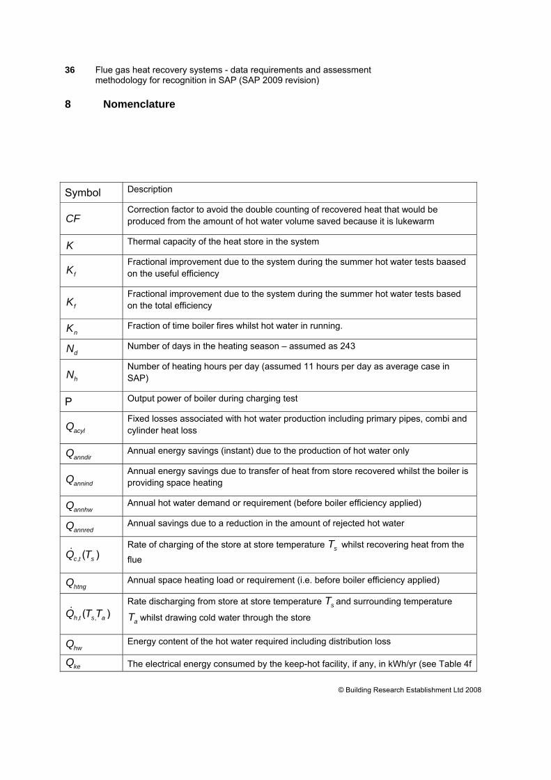
CF Correction factor to avoid the double counting of recovered heat that would be produced from the amount of hot water volume saved because it is lukewarm
K Thermal capacity of the heat store in the system
fK Fractional improvement due to the system during the summer hot water tests baased on the useful efficiency
fK Fractional improvement due to the system during the summer hot water tests based on the total efficiency
nK Fraction of time boiler fires whilst hot water in running.
dN Number of days in the heating season – assumed as 243
hN Number of heating hours per day (assumed 11 hours per day as average case in SAP)
P Output power of boiler during charging test
acylQ Fixed losses associated with hot water production including primary pipes, combi and cylinder heat loss
anndirQ Annual energy savings (instant) due to the production of hot water only
annindQ Annual energy savings due to transfer of heat from store recovered whilst the boiler is providing space heating
annhwQ Annual hot water demand or requirement (before boiler efficiency applied)
annredQ Annual savings due to a reduction in the amount of rejected hot water
, ( )c t sQ T& Rate of charging of the store at store temperature sT whilst recovering heat from the
flue
htngQ Annual space heating load or requirement (i.e. before boiler efficiency applied)
, ,( )h t s aQ T T& Rate discharging from store at store temperature sT and surrounding temperature
aT whilst drawing cold water through the store
hwQ Energy content of the hot water required including distribution loss
keQ The electrical energy consumed by the keep-hot facility, if any, in kWh/yr (see Table 4f
37 Flue gas heat recovery systems - data requirements and assessment methodology for recognition in SAP (SAP 2009 revision)
Appendix: Passive gas flue heat recovery device procedure
The following is reference 4. The highlighted item is under review. Passive flue gas heat recovery device (PFGHRD)
When fitted to a condensing boiler this device recovers heat from the flue products to pre-heat the domestic hot water supply. The heat recovered is mostly from condensation of water vapour in the flue products and the application of a PFGHRD is restricted to condensing boilers because non-condensing types are not generally adequately protected against the corrosive effects of condensate. Where the device has a heat store within it energy recovered during space heating production can also be used to later offset the heat required for providing domestic hot water. PFGHRDs were added recently to the Appendix Q procedures. A spreadsheet is available on the Appendix Q website that calculates the annual energy saving. For SAP version 9.81 these devices are incorporated into the SAP specification and a new table is added to the database providing the necessary data. The spreadsheet that is presently needed as an adjunct to SAP calculators will then become redundant. Data for PFGHRDs will be brought into SAP calculations only via the database. The SAP assessor selects the PFGHRD being used from a list offered by the software, identifying the device by means of brand name and model. The software then fetches the parameters needed from the database. (Note: it is not necessary for the boiler characteristics to be from the database. The procedure for a PFGHRD can be applied to any condensing boiler, whether from database, manufacturer declaration or SAP Table 4b.) The energy saving depends on the hot water usage and the space heating requirements. A data record for a PFGHRD includes a set of coefficients a, b and c defining a set of equations (typically 6 equations) relating energy saving in kWh to hot water provided by the boiler for different annual space heating requirements. The equations are of the form:
Saving = a ln(Qhw) + b Qhw + c (1)
where Qhw is the annual water heating requirement (i.e. box(39) + box(40) - box(50) ) provided by the boiler excepting storage, combi and primary heat losses, For each fuel for which the device has been tested there is a database record containing:
40 Flue gas heat recovery systems - data requirements and assessment methodology for recognition in SAP (SAP 2009 revision)
a) set of coefficients a, b and c for an instantaneous combi boiler without a keep hot facility b) set of coefficients a, b and c for use with all other boiler types c) the fraction of heat recovered instantly in a hot-water-only test, Kf
If the PFGHRD has no internal heat store the saving is
S = Kf × Kn × Qhw ÷ 0.91 (2)
where S is the saving due to the PFGHRD Kf depends on the characteristics of the PFGHRD and is provided in the database record Kn is defined by (6) below 0.91 is the efficiency of the boiler assumed in the regression equations
If the PFGHRD has an internal heat store the procedure is:
1) Obtain the space heating requirement of the main heating system (Qsp),
Qsp = [1 – box(82)] × box(81) (3)
2) From the database record, obtain the coefficients a, b and c for space heating requirements immediately above (Qsp1) and below (Qsp2) the actual space heating requirement Qsp. If the boiler is an instantaneous combi without keep-hot facility use the equations for instantaneous combi without keep-hot facility; for any other type of boiler use the equations for other boiler types and apply a correction according to the water storage arrangement in step 6).
3) Calculate the estimated saving for the space heating requirements immediately above (Qsp1) and below (Qsp2) the actual requirement using equation (1).
4) Using linear interpolation, estimate the saving, S0, for the actual space heating requirement (Qsp) of the main heating system from the saving for space heating requirements immediately above (Qsp1) and below (Qsp2).
5) If Qsp is greater than the largest value in the database record, calculate the saving using the equation for the largest value of space heating requirement in the database record.
6) If the boiler is an instantaneous combi without keep-hot facility omit this step and put S = S0. Otherwise amend the saving to include heat recovered while heating the hot-water store according to the water storage arrangement as follows.
a. In the case of a combi boiler with keep-hot facility,
S = S0 + 0.5 Kf [Qc – Qce] ÷ 0.91 (4)
where S is the saving due to the PFGHRD S0 is the saving calculated at step 4) Kf depends on the characteristics of the PFGHRD and is provided in the database record Qc is the applicable combi loss (SAP Table 3a) as at box(49) Qce is the electrical part of the energy used to maintain the keep-hot (SAP Table 4f), if any
41 Flue gas heat recovery systems - data requirements and assessment methodology for recognition in SAP (SAP 2009 revision)
0.91 is the efficiency of the boiler assumed in the regression equations 0.5 allows for the lower heat transfer to the PFGHRD store compared to heat transfer instantly to the cold water feed.
b. If the boiler is a storage combi, a regular boiler supplying a cylinder or thermal store, or a CPSU,
S = S0 + 0.5 Kf [Qloss – (1 – Kn) Qhw] ÷ 0.91 (5)
where S is the saving due to the PFGHRD S0 is the saving calculated at step 4) Qloss is the storage, combi and primary loss, equal to box(47) + box(48) + box(49) Kn is related to the coincidence of hot-water draw-off and boiler firing and is given by:
Kn = 0 if Vk ≥ 144
(6) Kn = 0.48 – Vk ÷ 300 if 75 ≤ Vk < 144
Kn = 1.1925 – 0.77 Vk ÷ 60 if 15 < Vk < 75
Kn = 1 if Vk ≤ 15
where Vk is the storage volume in the case of a regular boiler or a secondary storage combi Vk is 1.3 times the storage volume in the case of a primary storage combi or a CPSU
Include the result (i.e. S in kWh/year) in box (95), along with the applicable fuel. When savings are calculated for a PFGHRD, the adjustments to boiler efficiency given in Table 4c for underfloor heating and load/weather compensator are not applied. (There would be double counting if they were.) A PFGHRD should be offered as an option in the case of the main heating being from a boiler fired by mains gas, LPG or oil. It is not relevant for other heating systems. The saving is to be applied only if - the boiler is a condensing type, and - the fuel to which the PFGHRD data apply is the same as the boiler fuel (mains gas,