42
Fluid solutions Reliable with us. Gear pumps Exact with us. Flow measurement Strong with us. Hydraulics Safe with us. Valves

Fluid solutions
Reliable with us.
Gear pumps
Exact with us.
Flow measurement
Strong with us.
Hydraulics
Safewith us.
Valves


3
Your fluid solution partner
Content
Gear pumps 4 - 5 Overview 6 Shaft seals 7 Options / Valve options 8 Multiple pumps KF / KP and multiple combinations KF / KP + KM 9 Transfer pumps 10 KF 11 BT 11 Process pumps 12 DT 13 KF coated 13 ADP 14 Hydraulic pumps KP 14 Special pumps 15Flow measurement 16 - 17 Overview 18 GeartypeflowmetersVC 19 GeartypeflowmetersVCA 20 ScrewtypeflowmetersSVC 21 TurbineflowmetersTM 22 IO-Link version with internal calculation of measured values 23 Electronics 24 Valve position indicators 25Hydraulics 26 - 27 Overview 28 High pressure gear pumps KP 29 High pressure gear motors KM 29 Flow dividers 30 Hydraulic manifolds 30 Cylinders 31 Fan drives 32 - 33Valves 34 - 35 Pressure relief valves 36 - 39 Pressure control valves 40 Pressure stage control valves 40 Universal valves 41 Hydraulic manifolds 41 Directional control valves 41

Displacement 0.5 … 3 150 cm3/rev Media temperature -40 … 220 °C Maximum pressure … 315 bar
In addition to our standard products, in close cooperation with our customers we have develo-pedawiderangeofapplication-specificspecialsolutionsforfluidicapplications.On-scheduleperformance and a complete all-round service are our top priorities.
Benefitfromourdevelopments!
Get in touch with us. We would be glad to advise you.
Coated for abrasive media
DT
Low speed pumps for high viscosity media
BT
Standardgear pumps
KF
High pressure gear pumps
KP
Special pumps
SOP
Process pumps with special coating
KF coated
High precision metering pumps
ADP
RELIABLE AND ROBUST
Gear Pumps

Reliable with us.
- Low pressure pumps for gear lubrication as wellasforfilterandcoolingunits- Gear motors for fan drives- High pressure pumps for mobile and stationary hydraulic systems
Hydraulics
Our gear pumps can be used to pump fluidsthathaveacertainlubricity.Thesefluidsinclude,amongothers,oils,bra-kefluid,diesel,Skydrol,paints,polyol+isocyanate, adhesives, resins, greases, silicones, lacquers, wax, antifreeze and solvents.
Applications and media
- Pumps and motor pump units for dosing sys tems and mixing units- Dosing pumps for dosing and insulating, block and sandwich panel machines and RTM lines
Process technology
- Low pressure fuel pumps as feed or booster pump- Fuel pumps for marine diesel oil (MDO), heavy fuel oil (HFO) and marine gas oil (MGO)
Fuels
- Pumps for cooling liquids- Low pressure gear pumps and motor pump unitsforfiltrationandcoolingsystems- Gear pumps with universal valve for lubrication of wind power gearboxes- Pumps for adhesive dosing systems and for machinesforfibrereinforcement(rotorblade production)
Renewable energy
- Pumps and motor pump units for the lubriction of compressors- Pumps for the lubrication of couplings- Main and pre-lubrication pumps for engines and gearboxes - Fuel transfer pumps- Low pressure gear pumps for the lubrication of propellers and thrusters- High pressure gear pumps for controllable pitchpropelleroperation(CPP)
Marine

6
Gear Pumps
Gear pumps
I Transfer pumpsOur gear pumps are external gear pumps and are used as transfer pumps in the chemical and plastics indus-tries,inmarineapplications,generalfluidtransfer,inlubricating oil technology, in fuels and within renewa-ble energies.
Pages 10-11
I Process pumps Gear pumps for dosing liquids in process engineering processes. The pumps are used, for example, in hot meltadhesivesystemsandin1C,2Cormulti-compo-nent dosing systems.
Pages12-14
I Hydraulic pumps The hydraulic pumps are primarily used in oil-hydraulic systems.Theyaresuitableforgeneralhydraulicfluidsand motor oils.
Page 15
I Special pumps In addition to our standard products, we develop spe-cialpumpsforawiderangeoffluidtechnologyappli-cations in close cooperation with our customers. Feel free to get in touch with us.
Page 15
I Overview KRACHTisoneoftheleadingGermanmanufacturersof gear pumps for the marine, renewable energy, pro-cess technology, lubricating oil technology and hydrau-lics sectors.In addition to our standard products, we develop spe-cialpumpsforawiderangeoffluidtechnologyappli-cations in close cooperation with our customers.
The aim is to offer our customers the highest level of reliabilityandefficiency.Our gear pumps are suitable for the promotion of a wide range of media in numerous industrial areas. The main areas of application are lubricating oil and pro-cess technology as well as applications in mobile and industrial hydraulics.

7
Gear Pumps
Shaft seals
Without shaft sealing with outboard bearing
Example: Direct mounting to the motor or gearbox in connection with the absorption of radial forces
Single radial lip-type seal
Example:forgeneralfluidpumping
Single radial lip-type seal and outboard bearing
Example: to absorb radial forces
Double radial lip-type seal with connection possibility for quench
Example: for crystallizing media
Double radial lip-type seal for vacuum operation with connection possibility for quench
Example: for vacuum applications
Mechanical seal
Example: for increased upstream pressures
Mechanical seal with single radial lip-type seal and connection possibility for quench
Example: for increased upstream pressures in conjunction with crystallising media
Without shaft sealing
Example: Direct mounting to the motor or gearbox
Magnetic coupling
Example: for applications that require absolute tightness
Gland packing
Example: for slow running pumps with highly viscous media
Triple radial lip-type seal with connection possibility for quench
Example: for normal and vacuum operation

8
Gear Pumps
Options
I Versions• ATEX version• Stainless steel version• Motor-pump unit
(electrically / mechanically driven)• Noise-optimised version• Outboard bearing to absorb radial forces• Low temperature version
I Valve options
• Vacuum version• Multiple pumps• Heating jacket • Follower plate pump
D-Valve D15/D25 (mounted valve)Gear pumps of the KF series can optionally be equip-ped with a directly controlled pressure relief valve (D-valveD15/D25).Thebuilt-uppressurereliefvalveisa direct operated valve with a rising characteristic. It is used to protect the pump from short-term, impermis-sible pressure peaks. It must not be operated perman-ently as overpressure protection, as the valve or pump may overheat due to its design.If the valve responds over a longer period of time, valves with a separate tank connection, such as the T-valve(T-15/25)orvalvesinpipeconstructionsuchasthe SPV valve, should be used.
T-Valve T15/T25 (mounted valve)The T-valve is an attached, directly controlled pressure relief valve with separate tank connection. To dissipate heat,thehandledfluidflowingoutviatheT-valveisfed directly into the storage tank. Thanks to adapted damping, the valve offers very good control charac-teristics and outstanding dynamics with vibration-free operation at all operating points of the pump.
SPV/DV-valve (integrable valves)The SPV valve is a directly controlled pressure relief valve for installation in pipelines and is used to protect hydraulic circuits.DV series valves are hydraulically pilot-controlled and are available as DV B pressure relief valves, DV S pressure stage control valve and DV R pressure control valves.
Universal valve (mounted valve)Pumps with universal valve pump to the same pressure connection even when the direction of rotation of the drive shaft changes. This property guarantees lubrica-tion of the gearing mechanisms in pendulum mode, for instance, in wind turbines and marine propulsion systems.

9
Gear Pumps
Options
I Multiple pumps KF / KPGear pump KF + Gear pump KF
Gear pump KF + High pressure gear pump KP
High pressure gear pump KP + High pressure gear pump KP
High pressure gear pump KP + High pressure gear pump KP + High pressure gear pump KP
I Multiple combinations KF / KP + KMGear pump KF + High pressure gear motor KM
High pressure gear pump KP + High pressure gear motor KM

10
Gear Pumps
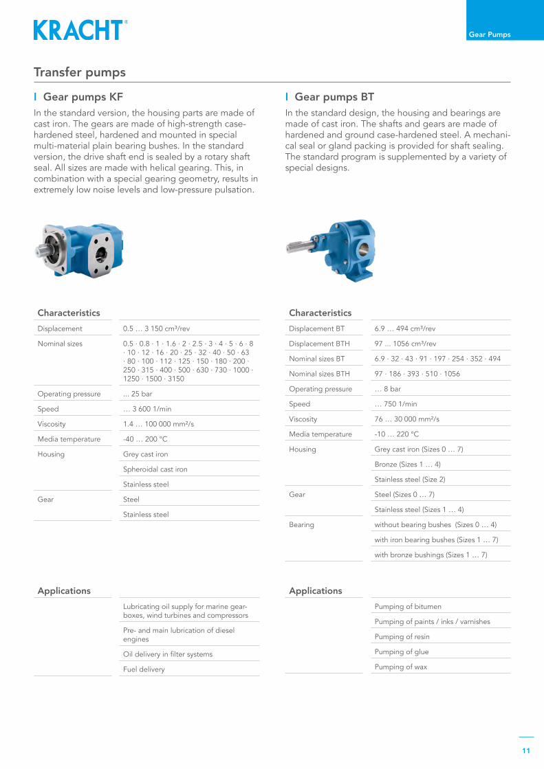
Transfer pumps
I Overview KF / BTKRACHTgearpumpsareexternalgearpumpsandareused as transfer pumps in the chemical and plastics industries,inmarineapplications,generalfluidtransfer,in lubricating oil technology, in fuels and within rene-wable energies. The pump housings are made of cast iron, spheroidal cast iron and stainless steel, the gear parts are made from high-quality steel. A wide range of sealing variants is available for the most diverse requirements.
I BTBT and BTH series pumps are low speed gear pumps for pumping a wide range of medium to high viscosity liquids, provided they ensure a certain minimum lubri-cation, do not contain solid particles and are chemical-ly compatible.
Page 11
I KFGear pumps KF are used to pump a wide range of liquids. The pumps impress in particular with their wide range of variants, which can be combined as required and also extended at a later date thanks to their mo-dular design. The pumps are also great for media with low lubricating properties.
Page 11
11
Gear Pumps
Transfer pumps
Characteristics Displacement 0.5 … 3 150 cm³/rev
Nominal sizes 0.5·0.8·1·1.6·2·2.5·3·4·5·6·8·10·12·16·20·25·32·40·50·63·80·100·112·125·150·180·200·250·315·400·500·630·730·1000·1250·1500·3150
Operating pressure ...25bar
Speed … 3 600 1/min
Viscosity 1.4…100000mm²/s
Media temperature -40…200°C
Housing Grey cast iron
Spheroidal cast iron
Stainless steel
Gear Steel
Stainless steel
ApplicationsLubricating oil supply for marine gear-boxes, wind turbines and compressors
Pre- and main lubrication of diesel engines
Oildeliveryinfiltersystems
Fuel delivery
ApplicationsPumping of bitumen
Pumping of paints / inks / varnishes
Pumping of resin
Pumping of glue
Pumping of wax
I Gear pumps KFIn the standard version, the housing parts are made of cast iron. The gears are made of high-strength case-hardened steel, hardened and mounted in special multi-material plain bearing bushes. In the standard version, the drive shaft end is sealed by a rotary shaft seal. All sizes are made with helical gearing. This, in combination with a special gearing geometry, results in extremely low noise levels and low-pressure pulsation.
I Gear pumps BTIn the standard design, the housing and bearings are made of cast iron. The shafts and gears are made of hardened and ground case-hardened steel. A mechani-cal seal or gland packing is provided for shaft sealing. The standard program is supplemented by a variety of special designs.
Characteristics Displacement BT 6.9…494cm³/rev
Displacement BTH 97...1056cm³/rev
Nominal sizes BT 6.9·32·43·91·197·254·352·494
Nominal sizes BTH 97·186·393·510·1056
Operating pressure … 8 bar
Speed …7501/min
Viscosity 76…30000mm²/s
Media temperature -10…220°C
Housing Greycastiron(Sizes0…7)
Bronze(Sizes1…4)
Stainlesssteel(Size2)
Gear Steel(Sizes0…7)
Stainlesssteel(Sizes1…4)
Bearing withoutbearingbushes(Sizes0…4)
withironbearingbushes(Sizes1…7)
withbronzebushings(Sizes1…7)

12
Gear Pumps
Process pumps
I DTDuroTec® gear pumps DT for abrasiveand poorly lubricating liquids.
Page 13
I KF coatedGearpumpsKFcoatedfordosingfluidsinprocessengineering processes.
Page 13
I Overview DT / KF coated / ADPDosing liquids is the main task in numerous process engineering processes. Polyol, isocyanate, plasticizers, resins and adhesives are some of the most important li-quids with a wide range of applications. Risks in dosing thesepartlytoxic,corrosiveandflammablefluidsmustbe excluded. Discover our process pumps. Standard andcustomisedpumpsfromKRACHT–foryourappli-cation, too.
I ADPHigh precision gear metering pump.
Page14

13
Gear Pumps
Process pumps
ApplicationsHotmeltadhesivesystemsandin1C,2Cormulti-componentdosingsystems
ApplicationsAs a dosing pump for PU components, plasticizers, resins, adhesives, lacquers, paints etc.
I DTThe DuroTec® gear pumps are primarily designed for multi-component systems in process technology. This pump offers a reliable alternative wherever liquids withhardfillershavetobeprocessed,wherestandardpumps do not achieve satisfactory service lives.
I KF coatedDosing liquids is the main task in numerous process engineering processes. The accuracy, uniformity and reproducibility with which these liquids can be proces-sed are decisive for the quality of the end product. The KRACHTprocesspumpKFcoatedisparticularlywell-suited for these applications.
Characteristics Nominal sizes DT 1 = 3.0 · 5.5 · 6.3 · 8 · 11 · 16 ·
22cm³/rev
DT3=63·100·125cm³/rev
DT5=150·200·250cm³/rev
Operating pressure ... 150 bar
Speed … 1 500 1/min
Viscosity 30…50000mm²/s
Media temperature …150°C
Housing Grey cast iron
Spheroidal cast iron
Stainless steel
Gear Special steel with wear-resistant and corrosion-resistant coating
CharacteristicsDisplacement 4.6...24.8cm³/rev
Nominal sizes 4·8·11·16·20·24
Operating pressure … 50 bar
Speed …20001/min
Viscosity 12…15000mm²/s
Media temperature -10…200°C
Housing Grey cast iron
Spheroidal cast iron
Gear Special steel with wear-resistant and corrosion-resistant coating

14
Gear Pumps
CharacteristicsDisplacement 0.1…20.0cm³/rev
Nominal sizes 0.1·0.3·0.6·1.2·1.8·2.4·3.0·4.8·6.0·12.0·20.0
Operating pressure ...200bar
Speed …2001/min
Viscosity νmin1.0mm²/s(depending on pressure and speed)νmax depending on inlet conditions, speed and motor power
Media temperature -20…200°C
Housing Stainless steel
Gear Stainless steel
ApplicationsMetering of polyols and isocyanates in polyurethane plants
Metering of resin and hardener in two and multi-components plants
Lubricating oil metering
I ADPThe ADP is a high precision external gear metering pump. With extremly small clearances and an optimal geargeometrytheADPhasaveryhighvolumetriceffi-ciencyalsoatdifficultcombinationse.g.highpressuretogether with low turning speed and low viscosities. The main parts of the pump are made of stainless steel.Becauseofthatawiderangeoffluidscanbepumped.
CharacteristicsDisplacement 1.4…300cm³/rev
Nominal sizes KP0 1·2·3·4·6·8KP1 3·4·5.5·6.3·8·11·14·16 19·22KP1S2 3·4·5.5·8·11·16·20KP2 20·25·28·32·40·50·62KP3 63·71·82·100·112·125KP5 160·200·250·300
Operating pressure ... 315 bar
Speed …40001/min
Viscosity 1.2…1400mm²/s
Media temperature -20…150°C
Housing
Aluminium
Grey cast iron
Spheroidal cast iron
Gear Steel
ApplicationsMobile and stationary plants
Constructionandagriculturalmachinery,municipal and special vehicles
I KPHigh pressure KP gear pumps are preferably used in oil hydraulic systems. The main components include thehousingandtheflangecover.Theycanwithstandhigh dynamic loads which means they are insensitive to pressure peaks and continuous vibrations. Thanks to their design and the materials used, the pumps are ideal for deployment under the toughest operating conditions.
Hydraulic pumpsProcess pumps

15
Gear Pumps
Special pumps
I SOPIn addition to our standard products, we develop spe-cial pumps in close cooperation with our national and internationalcustomers.Theyprovidespecificsolutionsforthemostdiversefluidtechnologyapplications.Feel free to get in touch with us. We would be glad to advise you.
Example applications1 Two-stage lubricating oil pump of a diesel engine2 Pre-lubricationpumpofadualfueldieselengine3 Direct driven diesel oil pump4 Directdrivenmainlubricatingoilpump with control valve5 Direct driven main lubricating oil pump for installtion in the engine sump6 Internal gear pump for gear lubrication7 Gearpumpforthelubricationofwindpowergears8 Pumps with heavy-duty outboard bearing

In addition to our standard products, in close cooperation with our customers we havedevelopedapplication-specificspecialsolutionsforfluidicmeasurementtechnology. The associated high-performance electronics process the signals suppliedbytheflowmeterandensurethatprocessesarepreciselymonitored,regulated and controlled.
Benefitfromourdevelopments!Get in touch with us. We would be glad to advise you.
Gear type flow meters
VCAAluminium
Electronics
AS 8Control unit
Electronics
SD 1Plug-on display
Electronics
ASR 30Control unit
Electronics
ASR 14Control unit
Screw type flow meters
SVCSpheroidal cast iron
Gear type flow meters
VCSpheroidal cast iron Stainless steel
Turbine flow meters
TMStainless steel
Valve position indicators
VOLUMEC
Measuring range 0.001 ... 3 750 l/minMedia temperature -60 ... 210 ℃Maximum pressure ... 480 bar
PRECISE|ECONOMICAL|ROBUST
Flow Measurement
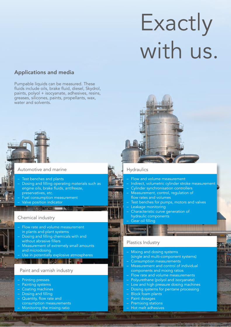
Pumpable liquids can be measured. These fluidsincludeoils,brakefluid,diesel,Skydrol,paints, polyol + isocyanate, adhesives, resins, greases, silicones, paints, propellants, wax, water and solvents.
Applications and media
– Testbenchesandplants– Dosingandfillingoperatingmaterialssuchas engineoils,brakefluids,antifreeze, preservatives, etc.– Fuelconsumptionmeasurement– Valvepositionindicator
Automotive and marine
– Flowandvolumemeasurement– Indirect,volumetriccylinderstrokemeasurement– Cylindersynchronisationcontrollers– Measurement,control,regulationof flowratesandvolumes– Testbenchesforpumps,motorsandvalves– Leakagemonitoring– Characteristiccurvegenerationof hydraulic components– Gearoilfilling
Hydraulics
– Printingpresses– Paintingsystems– Coatingmachines– Dosingandfilling– Quantity,flowrateand consumption measurements– Monitoringthemixingratio
Paint and varnish industry
– Mixinganddosingsystems (single and multi-component systems)– Consumptionmeasurements– Measurementandcontrolofindividual components and mixing ratios– Flowrateandvolumemeasurements– Polyurethane(polyolandisocyanate)– Lowandhighpressuredosingmachines– Dosingsystemsforpentaneprocessing– Blockfoamplants– Paintdosages– Premixingstations– Hotmeltadhesives
Plastics Industry
– Flowrateandvolumemeasurement in plants and plant systems– Dosingandfillingchemicalswithand withoutabrasivefillers– Measurementofextremelysmallamounts and microdosing– Useinpotentiallyexplosiveatmospheres
Chemicalindustry
Exactly with us.

18
Flow Measurement
Flow measurement
I GeneralFlow measurement: that means highly dynamic and highlyprecisevolumeandflowmeasurement,evalua-ted in an application-oriented method, from simple display devices to intelligent controller solutions. The powerful electronics processes the signals supplied by theflowmeterandensuresthatprocessesarepreciselymonitored, regulated and controlled.
For example in process technology as a controller unit fordosingandmixingsystemsorasflexiblemeasuringand recording electronics for differentiated applicati-ons in test bench construction.
I Gear type flow metersApplication-optimizedspecificationswithdifferingclearances, bearing variants and materials.
Pages19-20
I ElectronicsThe powerful electronics processes the signals sup-pliedbytheflowmeterandensuresthatprocessesareprecisely monitored, regulated and controlled.
Page24
I Turbine flow meters Predestined for use with low-viscosity media, such as water, cooling lubricants etc.
Page22
I Screw type flow meters Particularly suitable for highly viscous media with abra-sivefillers.
Page21
I IO-Link version with internal calculation of measured valuesFor bidirectional communication between any control levelandtheVCorSVCIO-Link.
Page23
I Valve position indicators Forthecontrolofhydraulicallyoperatedshipfittings
Page25

19
Flow Measurement
Gear type flow meters
Applications Fuel consumption measurement
Characteristiccurvegenerationof hydraulic components
Gearoilfilling
Indirect, volumetric cylinder strokemeasurement
Ratiomeasurementin2-andmulti-component dosing systems
Micro-flowmeasurementand micro-dosing
I VCGeartypeflowmetersforthemostdemandingtasksinfluidtechnologymeasurementtechnology.Ourexper-tise guarantees functional solutions. Standardised and application-optimised.
CharacteristicsMeasuring range 0.004l/min…80l/min
Nominal sizes 0.04·0.2·1
Typical measurement accuracy
up to +/- 0.3% of the measured value fromaviscosityof20mm²/s
Measured value resolution
…13157896Imp/l
Maximum pressure …480bar
Viscosity …2500000mm²/s
Media temperature -20…80°C
Housing Spheroidal cast iron
Gear Steel
I Encoder version with maximised measurement resolutionComparedwithstandardsensors,encodersareca-pable of generating considerably more pulses, thus increasing measurement resolution by orders of magni-tude.Encoder-equippedVCflowmetersgenerateupto2500pulsesperrevolutionandcanrecognisethedirectionofflow. Encoders, like the standard versions, send square-wave signals to the electronics.
Product characteristics
• High-precision measurement with outstanding reproducibility
• Wide measuring ranges with sizes graduated to meetspecificrequirements
• Application-optimizedspecifications• Low pressure drop• Anyflowdirection
• Noflowconditionersnesessary• Wide temperature range• High working pressure• Low noise emission• High-response measurement• ElectronicsinEMCcompliantdesign• RoHS compliant
CharacteristicsMeasuring range 0.001…700l/min
Nominal sizes 0.025·0.04·0.1·0.2·0.4·1·3·5·12·16
Typical measurement accuracy
up to +/- 0.3% of the measured value fromaviscosityof20mm²/s
Measured value resolution
… 160 000 Imp/l
Maximum pressure …480bar
Viscosity …2500000mm2/s
Media temperature -60…210°C
Housing Spheroidal cast iron
Stainless steel
Gear Steel
Stainless steel
20
Flow Measurement
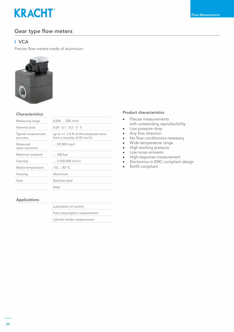
I VCAPreciseflowmetersmadeofaluminium
Characteristics Measuring range 0.004…200l/min
Nominal sizes 0.04·0.1·0.2·2·5
Typical measurement accuracy
up to +/- 1.0 % of the measured value fromaviscosityof20mm²/s
Measured value resolution
… 50 000 Imp/l
Maximum pressure …240bar
Viscosity …2500000mm2/s
Media temperature -10…80°C
Housing Aluminium
Gear Stainless steel
Steel
ApplicationsLubrication oil control
Fuel consumption measurement
Cylinderstrokemeasurement
Product characteristics • Precise measurements
with outstanding reproducibility• Low pressure drop• Anyflowdirection• Noflowconditionersnesessary• Wide temperature range• High working pressure• Low noise emission• High-response measurement• ElectronicsinEMCcompliantdesign• RoHS compliant
Gear type flow meters

21
Flow Measurement
Screw type flow meters
CharacteristicsMeasuring range 0.01...3750l/min
Nominal sizes 4·10·40·100·250
Typical measurement accuracy
upto+/-0.2%ofthemeasuredvaluefromaviscosityof20mm²/s
Measured value resolution
… 15 686 Imp/l
Maximum pressure …480bar
Viscosity …2500000mm²/s
Media temperature -40…210°C
Housing Spheroidal cast iron
Measuring spindles Heat-treated steel
ApplicationsFuel consumption measurement
Dosing systems
Process technology
Test bench construction
I SVCOurscrewtypeflowmetersincorporatetheproductcharacteristics robustness, high-precision measuring accuracy, good handling as well as durability and eco-nomy. Further advantages are resistance and insensiti-vity to contamination, pulsation free and low pressure drop. Particularly suitable for highly viscous media with abrasivefillers.
CharacteristicsMeasuring range 0.02…150l/min
Nominal size 10
Typical measurement accuracy
upto+/-0.2%ofthemeasuredvaluefromaviscosityof20mm²/s
Measured value resolution
...247463Imp./l
Maximum pressure …250bar
Viscosity …2500000mm²/s(durchflussabhängig)
Media temperature -20…80°C
Housing Spheroidal cast iron
Measuring spindles Heat-treated steel
I Encoder version with maximised measurement resolutionComparedwithstandardsensors,encodersareca-pable of generating considerably more pulses, thus increasing measurement resolution by orders of magni-tude.Encoder-equippedSVCflowmetersgenerateupto2500pulsesperrevolutionandcanrecognisethedirectionofflow.Encoders,likethestandardversions,send square-wave signals to the electronics.
Product characteristics
• High-precision measurement with outstanding reproducibility
• Pulsation-free measuring principle• Very low pressure drop• Anyflowdirection• Wide temperature range
• High working pressure• High-response measurement• Very low noise emission• ElectronicsinEMCcompliantdesign• RoHS compliant

22
Flow Measurement
Turbine flow meters
CharacteristicsMeasuring range 0.275...4000m3/h(4.6…66667l/min)
Nominal sizes 0.275·0.55·1.1·2.2·4·8·16·34·68·135·270·550·1100·1900·27004000
Maximum pressure …400bar
Media temperature -30…400°C
Typical measurement accuracy
up to ± 0.5% of the measured value
Housing Stainless steel
ApplicationsFlow measurement of water, cooling lubricants, emulsions and other lubricant and non-lubricant media.
Product characteristics • Very large measuring range• Very low pressure drop • High working pressure• Low noise emission• ElectronicsinEMCcompliantdesign• RoHS compliant
I TMKRACHTTMturbineflowmetersareprovenandwi-delyusedmeasuringdevicesinindustrialflowmeasu-rement technology. The instruments provide reliable, continuous and accurate measurement of liquids flowingunderpressureinclosedpipes.Thankstothestainlesssteeldesign,theflowmetersaresuitableforavariety of even aggressive media.

23
Flow Measurement
Signal processing and transfer to the IO-Link interface
SIO mode– Sameoutputofthetwosquare-wavesignals asinstandardpre-amplifier
M12x1
I Communication of the IO-Link assembly
IO-Link modeSignal output as described in the IODD according to the following units:– numberofpulses– litres...
3.0 3.1 2.9 3.1 3.0 3.1
SIO mode
I GeneralVC/SVCflowmeterswithIO-Linktechnologyarebasedonstandardflowmeterswithoneortwosensors.Unlike standard or encoder versions which always send a square wave signal to the electronics, IO-Link devi-ces have the added capability of internally computing concretemeasurementvalues.Therefore,theseflowmeterslendthemselvesforuseinclassicPLCandinIO-Link infrastructures. Thankstoitsinternationalstandardisation(IEC61131-9), the IO-Link technology offers point-to-point con-nectivity with continuous monitoring between any de-siredcontrollayerandtheVC/SVC-IO-Linkassembly.Handling and startup is made easy by the associated IODD(IODeviceDescription)file.TheVC/SVC-IO-Linkassemblydirectlydeliversallmea-sured values with units. In the preset SIO mode (stan-dard input output), the volume counter gives square-wave signals if the IO-Link mode is not enabled by an IO-Link master. This provides downward compatibility oftheVC-IO-Linkassemblywiththestandardsquare-wave signal
IO-Link version with internal calculation of measured values
IO-Link mode

24
Flow Measurement
Electronics
I Control units and plug-on displays The powerful electronics processes the signals sup-pliedbytheflowmeterandensuresthatprocessesare precisely monitored, regulated and controlled. It is used, for instance, in process technology as a cont-rolunitfordosingandmixingsystemsorasflexiblemeasuring and recording electronics for differentiated applications in test bench technology for use.
Applications • Flow control• Dosing• Fuel consumption measurement• Cylinderstrokemeasurementandmonitoring• Display and monitoring of added amounts• Display and monitoring of differential amounts• Display and monitoring of mixing ratio• Display and control of mixing ratio
I Control unit ASR 30The ASR 30 is a control unit which can be operated via touch screen. In addition, the unit can be expanded with manual operating units. This allows the imple-mentationofnumerousfluidtechnologyapplications.Standardised programs are available for various appli-cations. The ASR 30 programming can be optimally adapted to the respective application.
I Control unit ASR 14TheASR14integratescontrol,operationandvisu-alisation.TheASR14programmingcanbeoptimallyadapted to the respective application.
I Control unit AS 8The AS 8 control unit processes incremental input sig-nalsfromtheflowmeters.Theinputsignalsarefilteredin the unit, converted, and computed into the physical sizesofflowrateorvolumes.
I Plug-on display SD 1The SD 1 plug-on display is a universally applicable lo-caldisplayforallvolumecounterseries(VC,SVC,TM)with Hirschmann plugs. The display can show either flowrateorvolume.

25
Flow Measurement
VOLUMEC VOLUTRONIC®
Version Gear type volume counter Gear type volume counter
Flow range ... 150 l/min ... 10 l/min
Maximum pressure ... 300 bar ... 160 bar
Display mechanical by downstream electronic possible
Current-independentdisplay Yes –
Current-independentpositiondetection Yes No
Leakage detection Yes by downstream electronic possible
Valve position indicators
Channel I
Channel II
I VOLUMECThevalvepositionindicatorVOLUMECisaninterlin-king unit with the connection hole pattern for directly controlled NG 06 directional control valves. In detail, the module comprises a valve block, volume counter and display unit. Mounted on a connection plate and completed with a directional control valve, the VOLU-MECisusedtocontrolhydraulicallyoperatedshipval-ves for ballast, cargo or stripping systems, to measure and display the adjustment travel of the valve.The control module is designed for installation in deck boxes. The display of the volumetrically detected valve position can be read visually directly on site or electri-cally via potentiometer or limit switches.
Display device AVC (1)The display device is part of the volume counter and forms a mea-suring unit. It is completely sepa-rated from the hydraulic circuit.
Gear type flow meters VC (2)Gearflowtypemetersofnominalsizes02,04and5areavailable,whicharedesignedforflowsfrom4to150l/minandmaximumpressuresbetween200and300 bar.
Hydraulic manifold HB (3)TheVOLUMECvalvepositionindicatorcanbecombi-ned with different hydraulic manifolds to meet indivi-dual requirements.
I VOLUTRONIC®
TheVOLUTRONIC® valve position indicator differs fromthemechanicalVOLUMECbyitselectronicsignalprocessing.2incrementalsignalswitha90°phaseoffset are transmitted to the control, which enables thedirectiontobedisplayedinadditiontotheflowvolume.TheVOLUTRONIC® valve position measuring instrument can be used for a wide range of actuator sizes and travel speeds.

Hydraulics
High-pressure gear pumps and motors, fan drives, multiple combinations, valves and hydraulic manifolds as well as cylinders for construction machi-nery, municipal vehicles, agricultural machinery, special vehicles and truck bodies.
Benefitfromourdevelopments!Get in touch with us. We would be glad to advise you.
Hydraulic manifolds
HB
Cylinders
CNLBZ
High pressure gear motors
KM
Flow dividers
KM + KM
High pressure gear pumps
KP
EFFICIENT|ECONOMICAL|ROBUST
Fan drives
KM 1
Displacement KP/KM 1.0 ... 300 cm3/revMedia temperature -20 ... 150 ℃Maximum pressure ... 315 bar

Our hydraulic components are used in a host of different areas. Our high-pressure gear pumps are employed wherever motion is produced by pressurised oil. Our high-pressure gear motors translate hydraulic into mechanical force. The valves and cylinders are used in a multitude of applicationsinthefieldofoilandworkinghy-draulics.
Hydraulic components for mobile and stationary applications
Strongwith us.

28
Hydraulics
Hydraulics
I General High pressure gear pumps and motors, fan drives, mul-tiple combinations, valves and hydraulic manifolds as well as cylinders for construction machinery, municipal vehicles, agricultural machinery, special vehicles and truck bodies.
I High pressure gear motors KMHigh-pressure gear motors for oil-hydraulic systems. Multiple motor combinations are possible and the mo-tors can be supplied with mounted valves
Page29
I Flow dividers Flowdividersforefficientdistributionofpressuresandflows.
Page 30
I Hydraulic manifolds Customisedhydraulicmanifoldsforthedrivingandworking hydraulics.
Page 30
I CylindersHydraulic and block cylinders as differential, synchro-nous, pull or push cylinders as well as plunger cylin-ders.
Page 31
I Fan drives Individual cooling through adaptable motors with diffe-rent valve functions for each cooler brand.
Pages32-33
I High pressure gear pumps KPHigh-pressure KP gear pumps are preferably used in oil hydraulic systems. They are suitable for general hydraulicfluidsandengineoils.
Page29

29
Hydraulics
High pressure gear pumps High pressure gear motors
ApplicationsMobile and stationary plants
Constructionandagriculturalmachinery,municipal and special vehicles as a fan or other driveb
CharacteristicsDisplacement 5.5 … 300 cm³/rev
Nominal sizes KM1 5.5·6.3·8·9.6·11·14·16· 19·22·25KM1S2 5.5·8·11·16·20KM2 20·25·28·32·40·50·62KM3 63·71·82·100·112·125KM5 219·250·300
Operating pressure ... 315 bar
Speed …40001/min
Viscosity 1.2…1000mm²/s
Media temperature -20…150°C
Housing
Grey cast iron
Spheroidal cast iron
Aluminium
Gear Steel
CharacteristicsDisplacement 1.4…300cm³/rev
Nominal sizes KP0 1·2·3·4·6·8KP1 3·4·5.5·6.3·8·11·14·16 19·22KP1S2 3·4·5.5·8·11·16·20KP2 20·25·28·32·40·50·62KP3 63·71·82·100·112·125KP5 160·200·250·300
Operating pressure ... 315 bar
Speed …40001/min
Viscosity 1.2…1400mm²/s
Media temperature -20…150°C
Housing
Aluminium
Grey cast iron
Spheroidal cast iron
Gear Steel
ApplicationsMobile and stationary plants
Constructionandagriculturalmachinery,municipal and special vehicles
I KPHigh pressure KP gear pumps are preferably used in oil hydraulic systems. The main components include thehousingandtheflangecover.Theycanwithstandhigh dynamic loads which means they are insensitive to pressure peaks and continuous vibrations. Thanks to their design and the materials used, the pumps are ideal for deployment under the toughest operating conditions.
I KMKRACHTKMexternalgearmotorsaresuitablefordeployment under the toughest operating conditions thanks to their design and the materials used. The maincomponentsarethehousingandtheflangecover. They can be dynamically highly loaded, making them insensitive to pressure peaks and continuous vibrations.

30
Hydraulics
Flow dividers
Characteristics Displacement 5.45…25.97cm³/rev
KM1 5.5·6.3·8·9.6·11·14·16· 19·22·25
Operating pressure ...250bar
Speed …40001/min
Viscosity 10.0…600mm²/s
Media temperature …90°C
Housing Aluminium
Gear Steel
Applications Mobile and stationary plants
Constructionandagriculturalmachinery,municipal and special vehicles
CharacteristicsVolumeflow … 3 000 l/min
Maximum pressure ...480bar
Media temperature -30…200°C
Applications
Road and construction machinery
Municipal vehicles and agricultural machinery
Water jet cutting machines
Clutch-operatedmanualgears
Gear control
I KMTheflowdividerisahydrauliccomponent.Itisusedfortheefficientdistributionofpressuresandflows.Itdividesoraddsupatotalvolumeflowuniformlyorinafixeddivisionratio.Theconsumerpressuresarenotimportant.Asaresultofitsdesign,theflowdividerisaproven solution for various dividing tasks.
Hydraulic manifolds
I HBOur hydraulic manifolds are custom-made control units for driving and working hydraulics for mobile work ma-chines such as road and construction machines, munici-pal vehicles and agricultural equipment, or applications inthefieldofstationaryhydraulics.Theproductrangeincludes all necessary hydraulic functional elements and their designs (mono and sandwich blocks, instal-lation and structural elements). It is topped off with integrated electronic sensors, controls and actuating elements.

31
Hydraulics
Cylinders
CharacteristicsNominal pressure 400bar
Piston diameter 40…125mm
Stroke length … 500 mm
Lifting speed … 0.5 m/s
Pressure media tem-perature
-20…180°C
Viscosity 2.8…380mm²/s
Mounting position optional
Applications Differential cylinder
Synchronised cylinder
Push or pull cylinder
Plunger cylinder
ApplicationsDifferential cylinder
Synchronised cylinder
Push or pull cylinder
Plunger cylinder
Characteristics
Nominal pressure 200bar
Piston diameter 40…100mm
Stroke length …4000mm
Lifting speed … 0.5 m/s
Pressure media tem-perature
-20…180°C
Viscosity 2.8…380mm²/s
Mounting position optional
I Hydaulic cylinders CNLCylindersoftheCNLtypeseriesaredesignedaspureboltedconstructions.Cylinderheadsandbottomsaremade of steel. “Seamless precision steel tubes” accor-dingtoDIN2391areusedforthecylindertubesandhigh-strength steel is used for the ground, polished and hard-chrome plated piston rods.
I Block cylinders BZBlock cylinders are used for lifting, pressing and clam-pingintool,mouldandfixtureconstructionaswellasin machine tools.Withanominalpressureof400barandapistondia-meterofupto125mm,KRACHTprovidesprecisionand safety for a multitude of applications. The com-pact size as well as various mounting and connection options facilitate problem-free installation even where space is limited.
32
Hydraulics
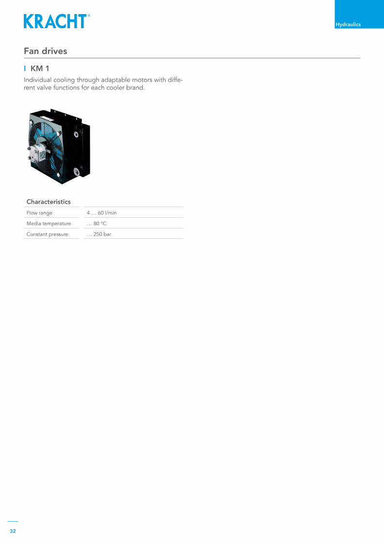
Fan drives
CharacteristicsFlow range 4…60l/min
Media temperature …80°C
Constantpressure …250bar
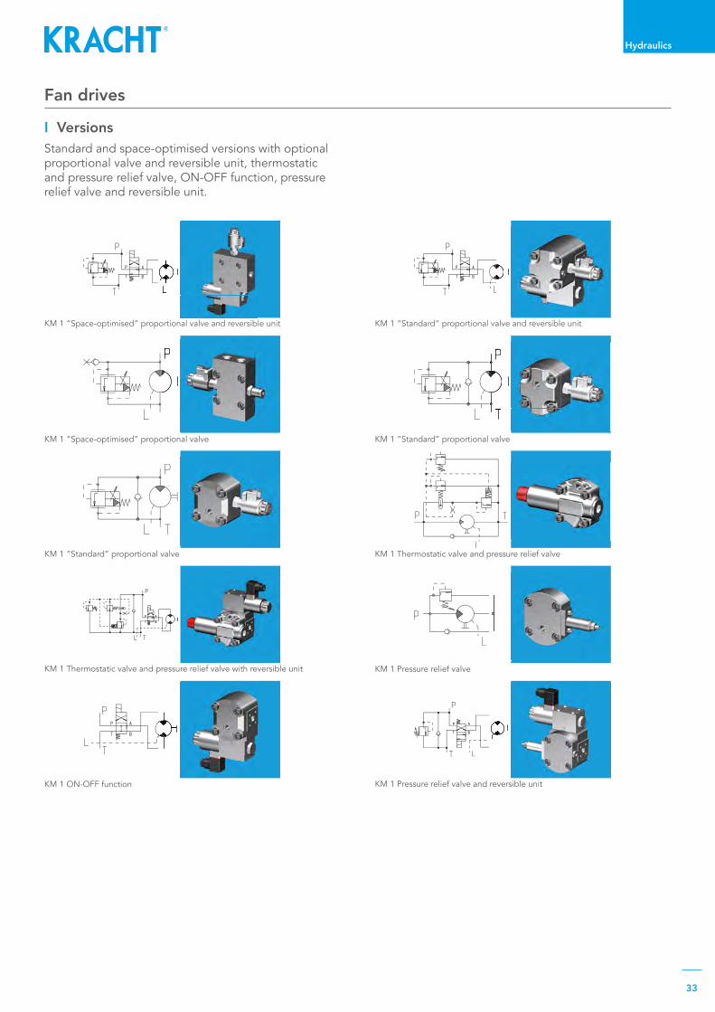
I KM 1Individual cooling through adaptable motors with diffe-rent valve functions for each cooler brand.
33
Hydraulics
KM 1 “Standard” proportional valve and reversible unit
KM 1 “Standard” proportional valve
KM 1 “Space-optimised” proportional valve and reversible unit
KM 1 “Space-optimised” proportional valve
KM 1 Thermostatic valve and pressure relief valveKM 1 “Standard” proportional valve
KM 1 Pressure relief valveKM 1 Thermostatic valve and pressure relief valve with reversible unit
KM 1 Pressure relief valve and reversible unitKM 1 ON-OFF function
Fan drives
I VersionsStandard and space-optimised versions with optional proportional valve and reversible unit, thermostatic and pressure relief valve, ON-OFF function, pressure relief valve and reversible unit.

Cetopvalvesforallrequirementsstationaryandmobileapplications.Pressure,switchingandstopvalveswithpipeconnectionforhighflowrates. Special valves.
Benefitfromourdevelopments!Get in touch with us. We would be glad to advise you.
Pressure relief valves
SPV / HV / TDBD / DV B / D
Pressure control valves
DV R
Hydraulic manifolds
HB
Directional control valves
WL
Universal valves
U2
Pressure stage control valves
DV S
RELIABLEANDAPPLICATION-OPTIMIZED
Volume flow ... 1 800 l/minMedia temperature -40 ... 220 ℃Nominal pressure ... 400 bar
Valves

Main areas of application: General mechanical engineering, plant engineering, construction ma-chinery, mining technology, chemical technology, diesel engines, vehicle technology, gear manu-facturing, refrigeration technology, compressor construction, power plant technology, plastics technology, offshore technology, test bench construction, shipbuilding, rolling mill industry, machine tools, wind turbines, two- and multi-component systems.
Valves
Safewith us.
Valves

36
Valves
Valves
I Universal valves Universal valves also deliver to the same connection when the direction of rotation of the pump changes. This means that the pressure and suction connectionremain constant, thus ensuring lubrication of the gear of wind turbines in rolling operation or vessels in „forward backward operation“ when the direction of rotation changes.
Page41
I Pressure control valves The DV R pressure control valve is a pilot-controlled pressure relief valve with external hydraulic activa-tion. It allows for the system pressure to be controlled irrespective of the pressure losses occurring between the valve and the point of the external control oil tap. Typical applications include pressure control in lubrica-ting grease circuits in diesel engines.
Page40
I Hydraulic manifolds Our hydraulic manifolds are custom-made control units for driving and working hydraulics for mobile work ma-chines such as road and construction machines, munici-pal vehicles and agricultural equipment, or applications inthefieldofstationaryhydraulics.Theproductrangeincludes all necessary hydraulic functional elements and their designs (mono and sandwich blocks, instal-lation and structural elements). It is topped off with integrated electronic sensors, controls and actuating elements.
Page41
I Pressure stage control valves The DV S pressure stage control valve is a pilot-control pressure relief valve with several parallel pilot valves set at two different pressures. The pressure stage switch valve has an integrated directional control valve. This valve is used to switch different pressure stages (upstream pressure) on and off. The control oil drain is internal or external. A typical application is clutch control in ship gearboxes.
Page40
I Pressure relief valves Pressure relief valves prevent system overloads. Dependingontheoperatingpressure,volumeflow,viscosity etc., appropriate valve solutions are available for all framework conditions, be it for rapid buffering of pressurepeaksorextremeflow-offrequirements.
Pages37-39
I Directional control valvesDirectional control valves are used to block or release different lines from one another and to create constant-ly changing line connections. In this way, the direction ofactionofpressuresandvolumeflowsisinfluencedand the consumer is controlled with regard to start, stop and direction of movement.
Page41

37
Valves
Pressure relief valves
CharacteristicsNominal sizes 10·25·40
Flow range 50 … 350 l/min
Operating pressure 160 bar
Viscosity 13…600mm²/s
Media temperature -20…150°C
Housing Gray cast iron
Spheroidal cast iron
Applications Protection of medium pressure hydraulic circuits
Characteristics Nominal sizes 10·20/25·32/40·50·80
Flow range 40…800l/min
Operating pressure 30 bar
Viscosity 1.2…1000mm²/s
Media temperature -40…220°C
Housing Gray cast iron
Spheroidal cast iron
Applications Protection of low-pressure hydraulic circuits
I SPV/SPVFThe SPV/SPVF pressure relief valve is a directly control-led slide valve for installation in pipelines and is used to safeguard low-pressure hydraulic circuits. The line connectioncanbemadeusingSAEflanges(3000psi)or Whitworth pipe threads (G).
I HV/HVFThe HV/HVF pressure relief valve is a pilot operated slide valve for installation in pipelines and thus serves to safeguard medium pressure hydraulic circuits up to max. 160 bar. The pipe connection can be made using SAEflanges(3000psi)orWhitworthpipethreads(G).Thanks to the spool pilot control, the valve can also be used for higher viscosities.

38
Valves
Pressure relief valves
Characteristics Nominal sizes 50 · 80
Flow range 800 … 1 800 l/min
Operating pressure …210bar
Viscosity 4…1000mm²/s
Pressure media temperature
-20…150°C
Housing Spheroidal cast iron
I DV BThe DV B pressure relief valves is a hydraulically pilot controlled valves. The control oil can be discharged either internally or externally. As standard, all designs are equipped with a measuring port and a connection for external control oil regulation. Typical applications are oil hydraulics and lubrication technology.On request, the DV B pressure relief valve is also avai-lablewithanadditional2/2-directionalcontrolvalve(e.g. for pressure-minimized circulation).
CharacteristicsNominal sizes 06·08·10·20
Flow range …200l/min
Operating pressure …400bar
Viscosity 10…600mm²/s
Pressure media temperature
-20…80°C
I DBDThe DBD pressure relief valve is a directly controlled poppet valve for installation in pipelines or as a cartrid-ge valve. The valve is used for pressure protection of hydraulicsystemsuptopmax=400bar.Thehousinghas two connections with Whitworth pipe threads for pipe mounting. Without the housing, the valve cartrid-gecanalsobescrewedintothespecifiedborecontourin any body instead.
39
Valves
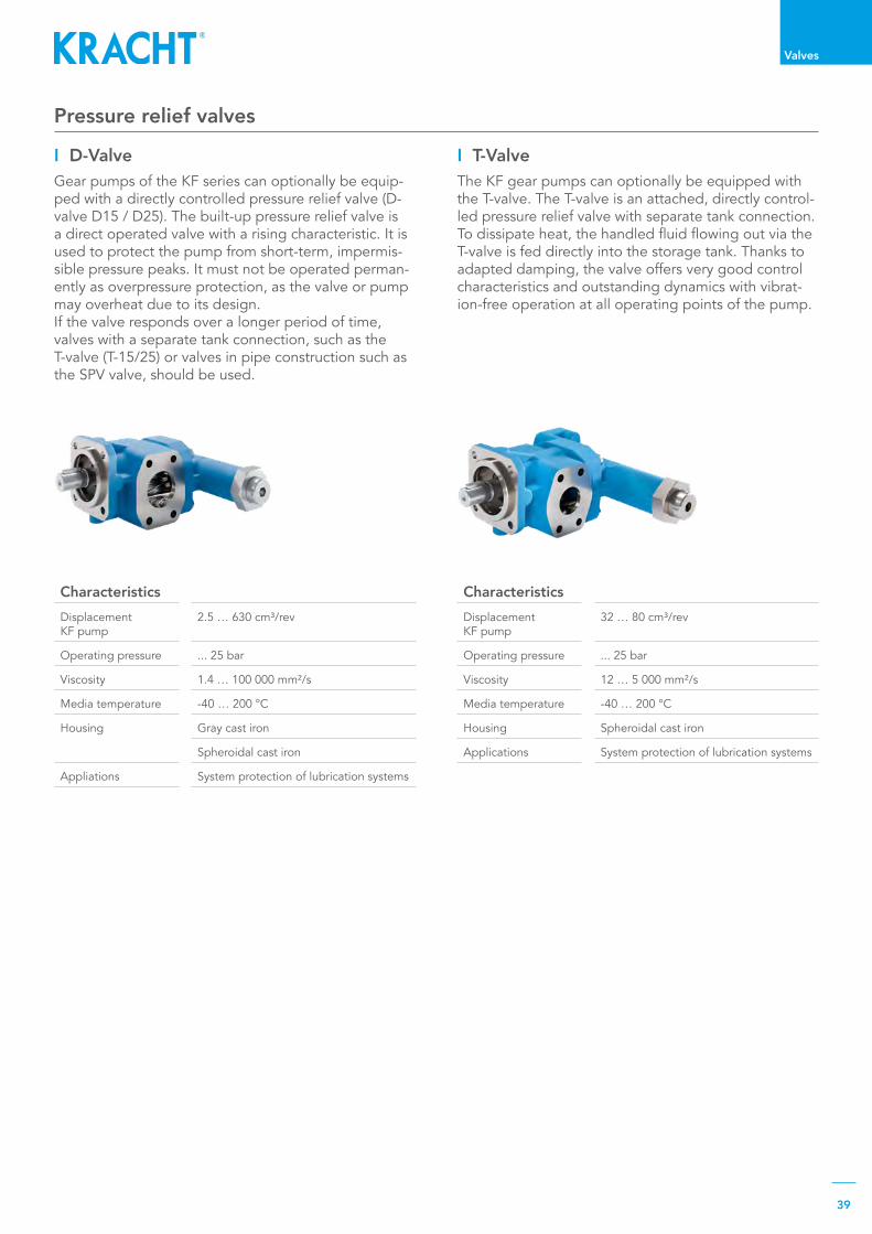
CharacteristicsDisplacement KF pump
32…80cm³/rev
Operating pressure ...25bar
Viscosity 12…5000mm²/s
Media temperature -40…200°C
Housing Spheroidal cast iron
Applications System protection of lubrication systems
CharacteristicsDisplacement KF pump
2.5…630cm³/rev
Operating pressure ...25bar
Viscosity 1.4…100000mm²/s
Media temperature -40…200°C
Housing Gray cast iron
Spheroidal cast iron
Appliations System protection of lubrication systems
I D-ValveGear pumps of the KF series can optionally be equip-ped with a directly controlled pressure relief valve (D-valveD15/D25).Thebuilt-uppressurereliefvalveisa direct operated valve with a rising characteristic. It is used to protect the pump from short-term, impermis-sible pressure peaks. It must not be operated perman-ently as overpressure protection, as the valve or pump may overheat due to its design.If the valve responds over a longer period of time, valves with a separate tank connection, such as the T-valve(T-15/25)orvalvesinpipeconstructionsuchasthe SPV valve, should be used.
I T-ValveThe KF gear pumps can optionally be equipped with the T-valve. The T-valve is an attached, directly control-led pressure relief valve with separate tank connection. Todissipateheat,thehandledfluidflowingoutviatheT-valve is fed directly into the storage tank. Thanks to adapted damping, the valve offers very good control characteristics and outstanding dynamics with vibrat-ion-free operation at all operating points of the pump.
Pressure relief valves

40
Valves
Pressure control valves Pressure stage control valves
CharacteristicsNominal sizes 50 · 80
Flow range 800 … 1 800 l/min
Operating pressure …210bar
Viscosity 4…1000mm²/s
Pressure media temperature
-20…150°C
Housing Spheroidal cast iron
CharacteristicsNominal sizes 50 · 80
Flow range 800 … 1 800 l/min
Operating pressure …210bar
Viscosity 4…1000mm²/s
Pressure media temperature
-20…150°C
Housing Spheroidal cast iron
I DV RThe DV R pressure control valve is a pilot-controlled pressure relief valve with external hydraulic activa-tion. It allows for the system pressure to be controlled irrespective of the pressure losses occurring between the valve and the point of the external control oil tap. Typical applications include pressure control in lubrica-ting grease circuits in diesel engines.
I DV SThe DV S pressure stage control valve is a pilot-control pressure relief valve with several parallel pilot valves set at two different pressures. The pressure stage switch valve has an integrated directional control valve. This valve is used to switch different pressure stages (upstream pressure) on and off. The control oil drain is internal or external. A typical application is clutch control in ship gearboxes.

41
Valves
Universal valves
CharacteristicsNominal sizes 6·10·16·25
Volumeflow …700l/min
Operating pressure … 330 bar
Viscosity 13…400mm²/s
Pressure media temperature.
-30…80°C
I U2-Valves The KF gear pumps can be optionally equipped with the universal valve. Pumps with universal valves pump to the same pressure connection even when the direc-tion of rotation of the drive shaft changes. Thanks to its principle of operation, the pressure and intake con-nections remain the same for any drive direction. This property guarantees lubrication of the gearing mecha-nisms in oscillation mode, for instance, in wind power and marine propulsion systems.
CharacteristicsDisplacement KF pump
2.5…112cm³/rev
Operating pressure ...25bar
Viscosity 12…100000mm²/s
Media temperature -40…200°C
Housing Gray cast iron
Spheroidal cast iron
Applications Wind turbines
Marine
CharacteristicsVolumeflow … 3 000 l/min
Maximum pressure ...480bar
Media temperature -30…200°C
Applications Road and construction machinery
Municipal vehicles and agricultural machinery
Water jet cutting machines
Clutch-operatedmanualgears
Gear control
Hydraulic manifolds
I HBOur hydraulic manifolds are custom-made control units for driving and working hydraulics for mobile work ma-chines such as road and construction machines, munici-pal vehicles and agricultural equipment, or applications inthefieldofstationaryhydraulics.Theproductrangeincludes all necessary hydraulic functional elements and their designs (mono and sandwich blocks, instal-lation and structural elements). It is topped off with integrated electronic sensors, controls and actuating elements.
Directional control valves
I WL

KRACHT GmbH · Gewerbestraße 20 · 58791 Werdohl, GermanyPhone +49 2392.935 0 · Fax +49 2392.935 209
E-Mail [email protected] · Web www.kracht.eu
Product_Overview/EN/04.2021
I ValvesCetopvalvesforallrequirementsstationaryand mobile applications. Pressure, switching and stop valves with pipe connection for highflowrates.Specialvalves.
I HydraulicsSingle and multistage high-pressure gearpumps, gear motors and valves forconstruction machinery, municipal vehicles,agricultural vehicles, special vehicles andtruck bodies.
I Flow MeasurementGear,turbineandscrewtypeflowmetersandelectronicsforvolumeandflow,metering and consumption in the chemicalindustry, hydraulic, process and test benchtechnology.
I Gear PumpsLow and high-pressure gear pumps forlubricating oil, hydraulic, process and testbench applications, fuel and meteringsystems.
Pro
duct P
ortfo
lio
Errors and technical changes reserved


