41
Fluid-Structure Interaction (FSI) with System Coupling © 2012 ANSYS, Inc. February 23, 2012 1 Dr Jasper Kidger ANSYS UK Ltd.

Fluid-Structure Interaction (FSI) with System Coupling
© 2012 ANSYS, Inc. February 23, 20121
Dr Jasper Kidger
ANSYS UK Ltd.

System Coupling (FSI) Introduction
© 2012 ANSYS, Inc. February 23, 20122

• Review of pre-R14 Solutions for ANSYS Fluent
• Motivation for System Coupling
• Features available
Outline
© 2012 ANSYS, Inc. February 23, 20123
• Demonstration of using System Coupling
• Gallery
• Questions

Brief Review of “Pre” R14 FSI Solutions for ANSYS Fluent
© 2012 ANSYS, Inc. February 23, 20124

One-Way FSI in Workbench
• Default approach in Workbench is where data is transferred and
© 2012 ANSYS, Inc. February 23, 20125
• Default approach in Workbench is where data is transferred and
mapped using ANSYS CFD-Post
• Supports both thermal and structural loads
• Surface Temperature
• Heat Transfer Coefficient
• Pressure (i.e. Stress Vector)
• Volumetric Temperature
• All “non-conservative” mapping even for similar meshes

Outside of Workbench
• 1-way FSI could be performed using a the
‘FSI Mapping’ Toolkit in Fluent.
– Compute CFD solution first
– Read FEA mesh into Fluent
– Fluent acts as an interpolation tool, exporting
CFD results at FEA mesh locations
© 2012 ANSYS, Inc. February 23, 20126
CFD results at FEA mesh locations
• 2-way FSI required an external software tool (MpCCI from Fraunhofer SCAI)
– Required additional 3rd party license

System Couplings Motivation
© 2012 ANSYS, Inc. February 23, 20127

• Common tool within Workbench for 2-way transfer of data between any of
our solvers.
- Rather than having a specific import tool for each solver combination:
- ANSYS Mechanical has a function for Fluent data import
Introducing System Couplings
General Motivation
© 2012 ANSYS, Inc. February 23, 20128
- And another function for CFX data import
- Etc...
• Each solver needs just one adaptor to exchange data with the coupling server
- Therefore any solver that is SC enabled can exchange data with any other
- ANSYS Mechanical exchanges data with just System Coupling

Generalized Vision for System Couplings in Workbench
Structural
Solver ‘X’
Co-Simulation
(Solvers)
Coupling Source Data
(Solvers)
Coupling Source Data
(External)
Structural
Solver ‘X’
© 2012 ANSYS, Inc. February 23, 20129
Available at R14Available at R14R15+R15+Planned at R14.5 for FLUENT/Mechanical SolversPlanned at R14.5 for FLUENT/Mechanical Solvers
Transient Structural
Solver System
Transient Structural
Solver System
R15+R15+

What is Supported at R14?
© 2012 ANSYS, Inc. February 23, 201210

• Two-way surface (3D) force/displacement coupling with
ANSYS Fluent and ANSYS Mechanical
• Workbench based setup and execution
• Parameterization, design exploration and optimization
• Windows (32/64-bit) and Linux (64-bit)
• Integrated post-processing with ANSYS CFD-Post
System Coupling 14.0: A Broad Range of Capabilities
© 2012 ANSYS, Inc. February 23, 201211
• Integrated post-processing with ANSYS CFD-Post
• Parallel processing for both Fluent and
Structural/Mechanical solutions with ANSYS HPC
• Restarts for fluid-structure interaction
• No special licensing required other than minimum ANSYS
license must be Structural

Technical Review(Workflow)
© 2012 ANSYS, Inc. February 23, 201212
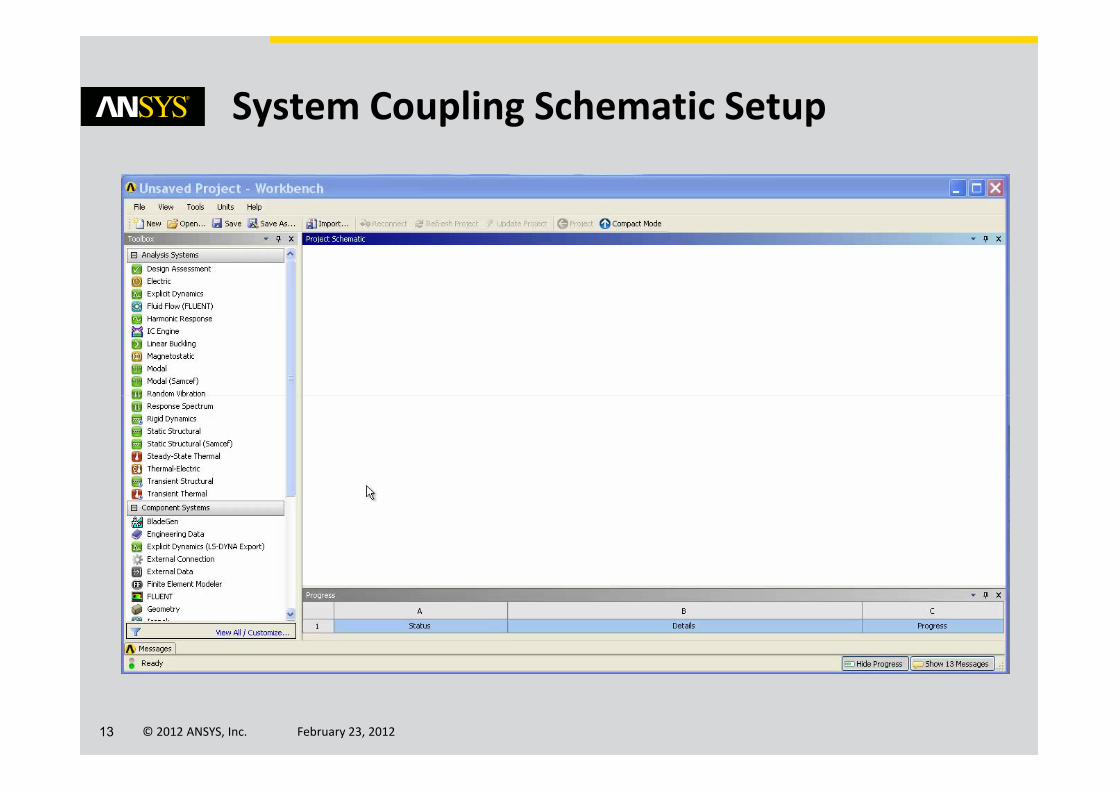
System Coupling Schematic Setup
© 2012 ANSYS, Inc. February 23, 201213

• Solution update can ONLY be done via System Coupling component
• System Coupling ensures that the time duration and time step settings are
consistent across all participant solvers
System Coupling Controls the Participant Solvers for Transient and Steady/Static Solutions
© 2012 ANSYS, Inc. February 23, 201214
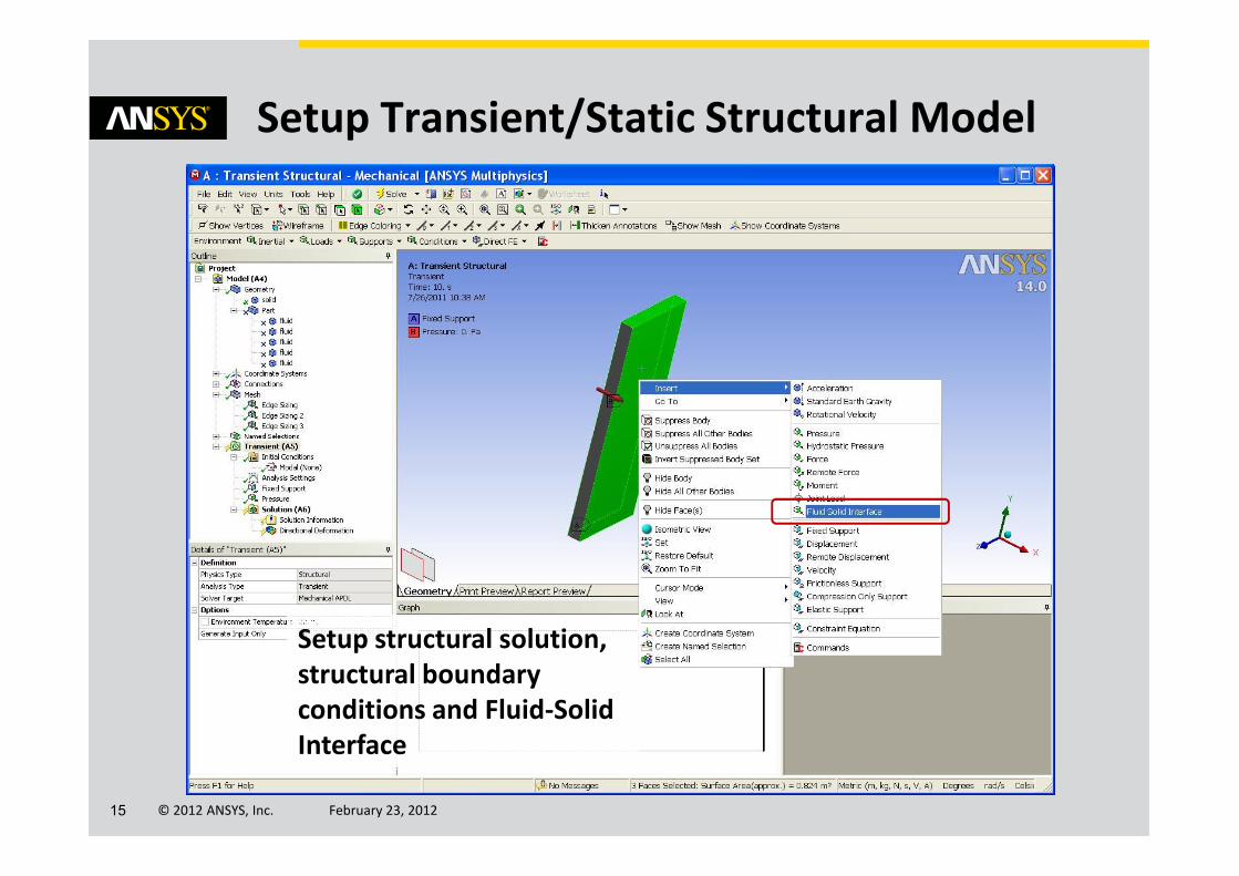
Setup Transient/Static Structural Model
© 2012 ANSYS, Inc. February 23, 201215
Setup structural solution,
structural boundary
conditions and Fluid-Solid
Interface
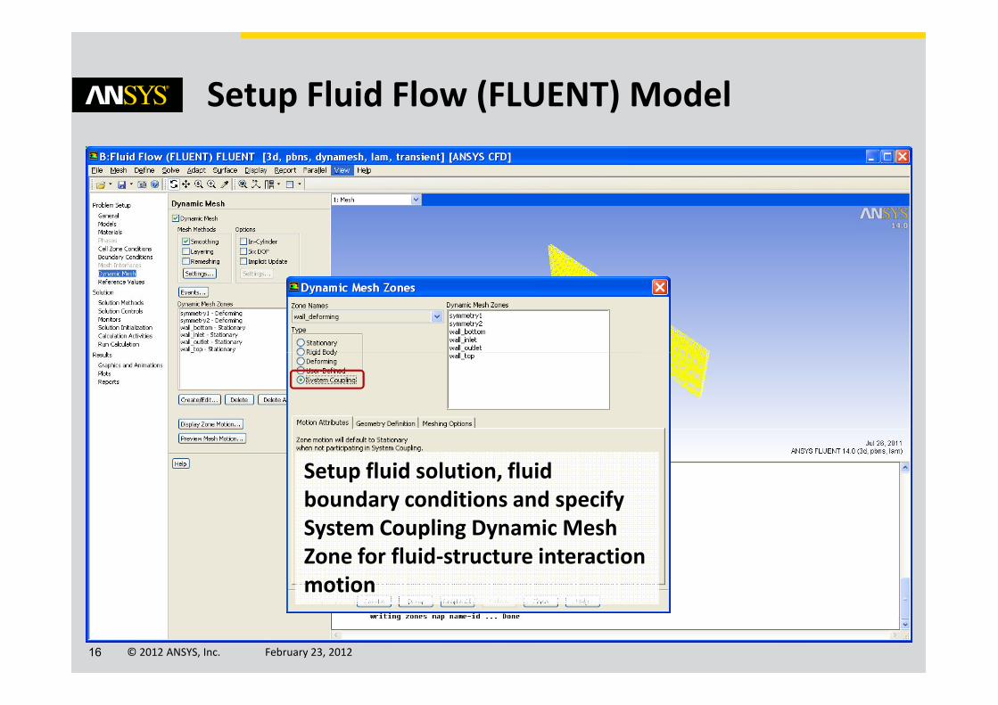
Setup Fluid Flow (FLUENT) Model
© 2012 ANSYS, Inc. February 23, 201216
Setup fluid solution, fluid
boundary conditions and specify
System Coupling Dynamic Mesh
Zone for fluid-structure interaction
motion

• State of System Coupling setup cell will be
– Upstream data is now available for SC Setup
Update Setup Cells for Transient/Static Structural and Fluid Flow (FLUENT)
© 2012 ANSYS, Inc. February 23, 201217
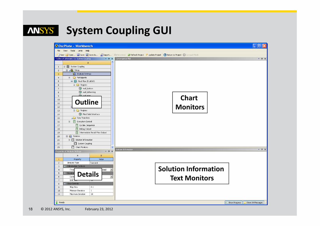
System Coupling GUI
Chart
MonitorsOutline
© 2012 ANSYS, Inc. February 23, 201218
Solution Information
Text MonitorsDetails

• Coupling End Time
– If both participants are transient
– For General, Number of Steps is
user input
• Coupling Step Size
– If both participants are transient
System Coupling Analysis Settings
© 2012 ANSYS, Inc. February 23, 201219
– If both participants are transient
– Note this overwrites values set in
Fluent / Mechanical interfaces
• Minimum Number of Iterations per
Coupling Step
• Maximum Number of Iterations per
Coupling Step

• Region and variable information is
generated automatically via
Update when analysis systems are
first connected to System
Coupling
System Coupling Participants are Transient/Static Structural and Fluid Flow (FLUENT)
© 2012 ANSYS, Inc. February 23, 201220
• For Fluent, all regions of type Wall
are shown in SC Setup
• For Mechanical, all regions of type
Fluid-Solid Interface are shown in
SC Setup

• Use Ctrl key to select a Fluent and
Mechanical region pair and select
Create Data Transfer from right-
click pop-up menu
• Automatically fills in the details
Recommended Way to Create Data Transfer Regions
© 2012 ANSYS, Inc. February 23, 201221
• Automatically fills in the details
for the data transfer region
• Data transfers can be one-way
(i.e. only transfer force or only
transfer displacement) or two-way

Create Data Transfers
© 2012 ANSYS, Inc. February 23, 201222
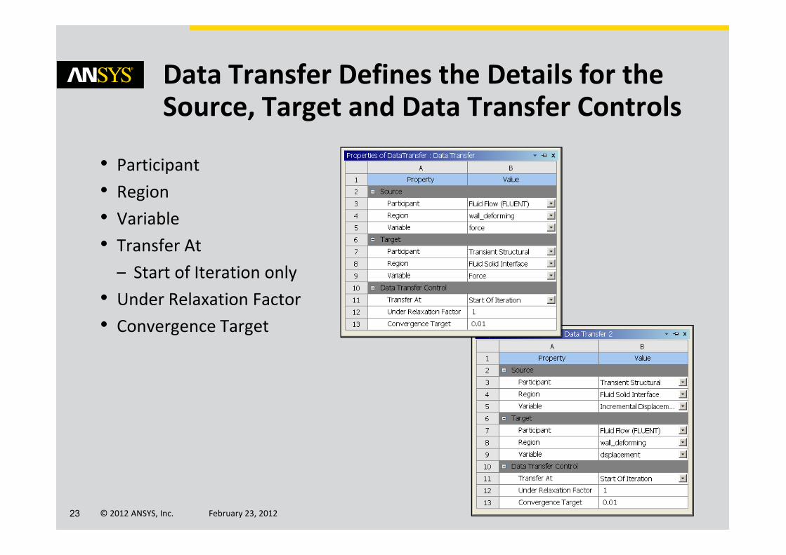
• Participant
• Region
• Variable
• Transfer At
– Start of Iteration only
Data Transfer Defines the Details for the Source, Target and Data Transfer Controls
© 2012 ANSYS, Inc. February 23, 201223
– Start of Iteration only
• Under Relaxation Factor
• Convergence Target

• Co-Simulation Sequence
– Transient or Static Structural will always
be first in the co-simulation sequence
• Debug Output
– Different levels of debug output for
analysis and data transfers
Execution Control
© 2012 ANSYS, Inc. February 23, 201224
analysis and data transfers
• Intermediate Results File Output
– Controls the intervals for writing restart
file information
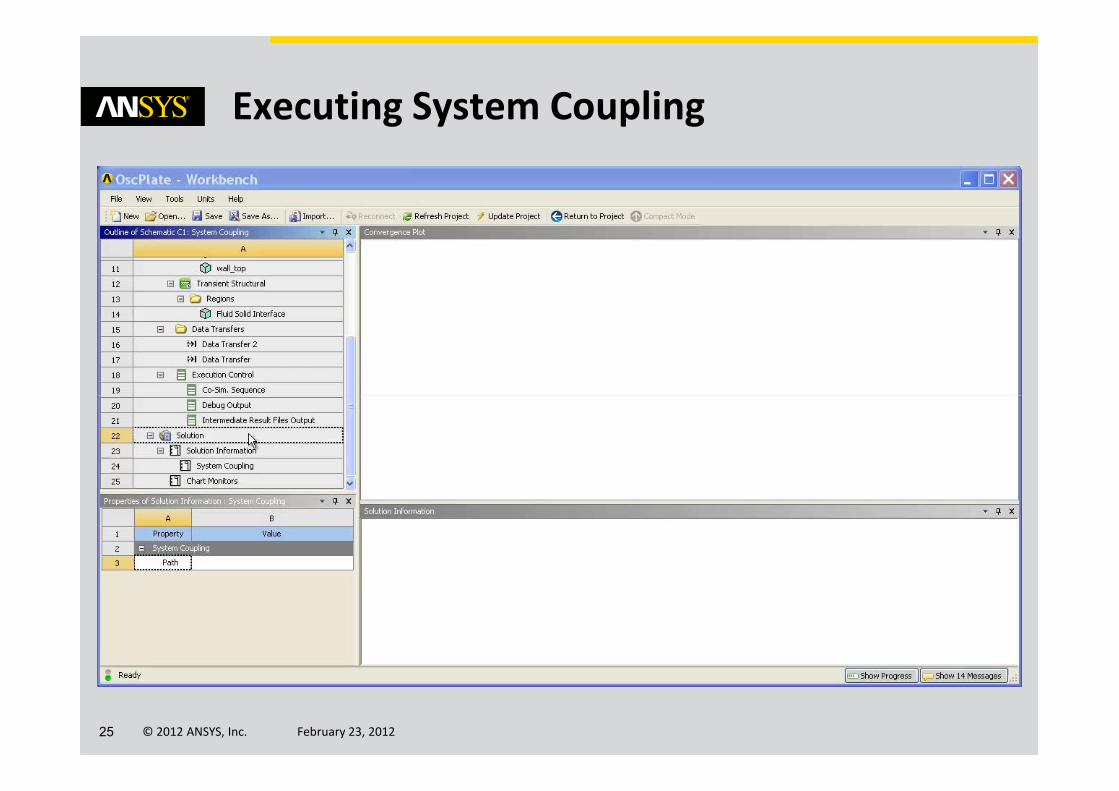
Executing System Coupling
© 2012 ANSYS, Inc. February 23, 201225

• From schematic select Update using right-click menu on
System Coupling solution cell
• Solution progress (% complete) can be monitored using
View Progress menu
Alternative Method for Executing System Coupling
© 2012 ANSYS, Inc. February 23, 201226

• Build information
• Complete summary of coupling
service input file
• Analysis details
• Participant summaries
• Data transfer details
Solution Information
© 2012 ANSYS, Inc. February 23, 201227
• Data transfer details
• Mapping diagnostics
• Time step and iteration summary
• Solver field equation convergence
summary
• Data transfer convergence
summary
• Fluent/MAPDL solver output

Chart Monitors
© 2012 ANSYS, Inc. February 23, 201228
Default chart monitors
show convergence
history for all data
transfers.
X-axis can be
coupling time,
step or
iteration.

• Transient/Static Structural or Fluid Flow (FLUENT)
Results cell for solver-specific post-processing
• Connect structural Solution cell directly to Fluent system
Results cell or add a Results System (ANSYS CFD-Post)
for unified post-processing of structural and fluid results
Post Processing System Coupling
© 2012 ANSYS, Inc. February 23, 201229

• Oscillating Plate Verification
– Excellent correlation between
System Coupling, published
data and MFX solver
Post Processing System Coupling
© 2012 ANSYS, Inc. February 23, 201230

Application Examples
© 2012 ANSYS, Inc. February 23, 201231
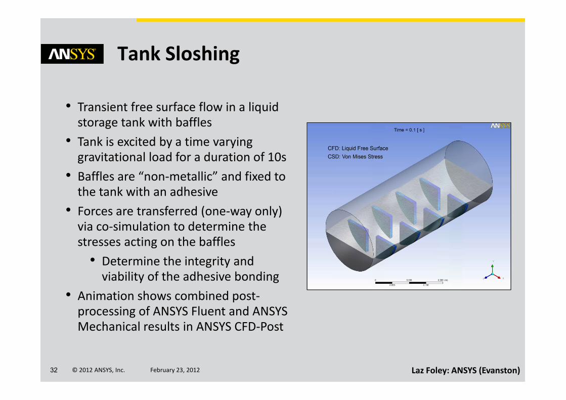
Tank Sloshing
• Transient free surface flow in a liquid
storage tank with baffles
• Tank is excited by a time varying
gravitational load for a duration of 10s
• Baffles are “non-metallic” and fixed to
the tank with an adhesive
© 2012 ANSYS, Inc. February 23, 201232
• Forces are transferred (one-way only)
via co-simulation to determine the
stresses acting on the baffles
• Determine the integrity and
viability of the adhesive bonding
• Animation shows combined post-
processing of ANSYS Fluent and ANSYS
Mechanical results in ANSYS CFD-Post
Laz Foley: ANSYS (Evanston)
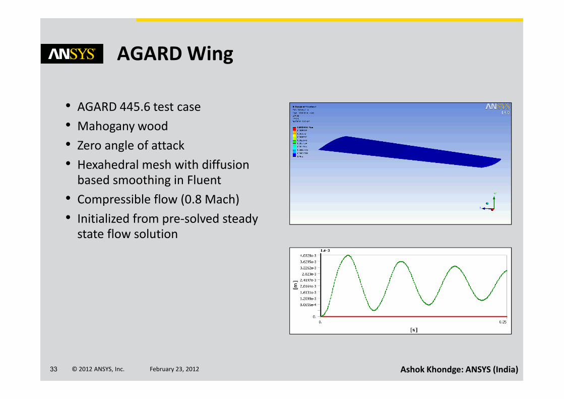
AGARD Wing
• AGARD 445.6 test case
• Mahogany wood
• Zero angle of attack
• Hexahedral mesh with diffusion
based smoothing in Fluent
• Compressible flow (0.8 Mach)
© 2012 ANSYS, Inc. February 23, 201233 Ashok Khondge: ANSYS (India)
• Compressible flow (0.8 Mach)
• Initialized from pre-solved steady
state flow solution

Liquid Pouring
• “Gulping” liquid stream behavior in a
non-rigid package/carton design
• Determine how pouring is affected by
package design, opening design and
fluid properties
• Diffusion based smoothing used in
Fluent to cater for deformation of
© 2012 ANSYS, Inc. February 23, 201234
Fluent to cater for deformation of
package walls
• Fluent models used include VOF and LES
• This “tightly” coupled solution requires
stabilization method for successful
analysisModel courtesy of Tetra Pak
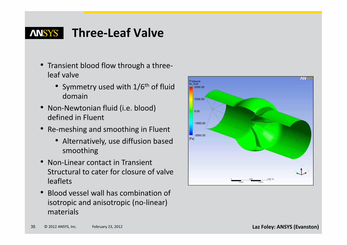
Three-Leaf Valve
• Transient blood flow through a three-
leaf valve
• Symmetry used with 1/6th of fluid
domain
• Non-Newtonian fluid (i.e. blood)
defined in Fluent
© 2012 ANSYS, Inc. February 23, 201235
• Re-meshing and smoothing in Fluent
• Alternatively, use diffusion based
smoothing
• Non-Linear contact in Transient
Structural to cater for closure of valve
leaflets
• Blood vessel wall has combination of
isotropic and anisotropic (no-linear)
materials
Laz Foley: ANSYS (Evanston)
Online Resources and Documentation
© 2012 ANSYS, Inc. February 23, 201236

System Coupling Documentation
© 2012 ANSYS, Inc. February 23, 201237 Available in HTML and PDF Formats

System Coupling Tutorial
© 2012 ANSYS, Inc. February 23, 201238
• Tutorial input file available on ANSYS Customer Portal by using the Download
Wizard to download ANSYS_Fluid_Dynamics_Tutorial_Inputs.zip

Best Practices
© 2012 ANSYS, Inc. February 23, 201239
• User documentation contains a dedicated section on
Best Practice Guidelines for Using System Coupling

Training Course• 2-day Training course is currently being written for System Coupling
• Predicted to be ready in March 2012
© 2012 ANSYS, Inc. February 23, 201240

Any Questions?
© 2012 ANSYS, Inc. February 23, 201241


