33
Fluid Thrust Chamber Design Kevin Cavender, Den Donahou, Connor McBride, Mario Reillo, Marshall Crenshaw 1 1

Fluid Thrust Chamber Design
Kevin Cavender, Den Donahou, Connor McBride, Mario Reillo, Marshall Crenshaw
11

Fluid Thrust Chamber Design
Kevin Cavender, Den Donahou, Connor McBride, Mario Reillo, Marshall Crenshaw
33
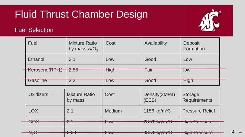
Fuel Selection
Fluid Thrust Chamber Design
Oxidizers Mixture Ratio
by mass
Cost Density(2MPa)
(EES)
Storage
Requirements
LOX 2.1 Medium 1156 kg/m^3 Pressure Relief
GOX 2.1 Low 28.73 kg/m^3 High Pressure
N2O 6.08 Low 38.78 kg/m^3 High Pressure
Fuel Mixture Ratio
by mass w/O2
Cost Availability Deposit
Formation
Ethanol 2.1 Low Good Low
Kerosene(RP-1) 2.56 High Fair low
Gasoline 3.2 Low Good High
44

Performance Parameters
Fluid Thrust Chamber Design
55
Characteristic Velocity
900 m/s to 2500 m/s
Stay time
0.001 to 0.040 sec
Characteristic Length
Typically 0.8 to 3.0 Meters for
bipropellants (sutton)
Huzel, Dieter, and David Huang. "Introduction." Modern
Engineering for Design of Liquid-Propellant Rocket
Engines. Vol. 147. Washington D.C.: AIAA, 1992. 7-22.
Print.
Sutton, Rocket Propulsion
Elements 7th edition

Outline
Fluid Thrust Chamber Design
66Sutton, Rocket Propulsion
Elements 7th edition

Fluid Injectors and Injector Heads
Fluid Thrust Chamber Design
77
Selection Considerations
● Types of injector elements
● Number of elements/manifold design
● Selecting injector elements dependant on
the the phase of the fluids being injected
● Manufacturing capabilities
● Heat transfer and combustion stability
http://www.dailytech.com/3D+Printed+Rocket+Engine+Injector+Desig
ned+Tested/article31959.htm

Fluid Injectors and Injector Heads
Fluid Thrust Chamber Design
Liquid-Liquid
Elements● Like and Unlike Elements
● Mixing Efficiency vs. Mass Distribution
88Huzel, Dieter, and David Huang. "Introduction." Modern Engineering for Design of Liquid-Propellant Rocket Engines. Vol. 147. Washington D.C.: AIAA, 1992.
7-22. Print.

Fluid Injectors and Injector Heads
Fluid Thrust Chamber Design
Gas-Liquid
Elements
99
● Requires Phase change of one of our
propellants from liquid to gas
Huzel, Dieter, and David Huang. "Introduction." Modern Engineering for Design of Liquid-Propellant Rocket Engines. Vol. 147. Washington D.C.: AIAA, 1992.
7-22. Print.

Fluid Injector Impingement Patterns
Fluid Thrust Chamber Design
1010
● Conservation of Momentum
● Heat transfer to outer walls
● Reduce vortexing in the corner
● Account for different exit velocitiesFor ℽ = 0 (axially aligned stream)
Sutton, George Paul, and Oscar Biblarz. "Thrust Chambers." Rocket Propulsion
Elements. 7th ed. New York: John Wiley & Sons, 2001. Print.

Fluid Injector Manifolds
Fluid Thrust Chamber Design
1111
http://arstechnica.com/science/2013/04/how-
nasa-brought-the-monstrous-f-1-moon-rocket-
back-to-life/1/
Sutton, George Paul, and Oscar Biblarz. "Thrust Chambers."
Rocket Propulsion Elements. 7th ed. New York: John Wiley &
Sons, 2001. Print.
Corrected Mixture Ratio for
injector testing
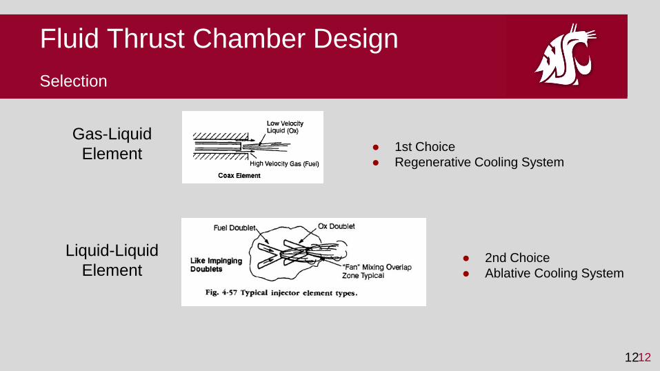
Selection
Fluid Thrust Chamber Design
Liquid-Liquid
Element
1212
Gas-Liquid
Element● 1st Choice
● Regenerative Cooling System
● 2nd Choice
● Ablative Cooling System

Heat Transfer - Introduction
Why is heat transfer important in rocket design?
● Guides the design, testing and failure
investigations
● The thrust chamber must be cooled in order to
withstand imposed loads and stresses
General idea of steady-state cooling methods
● Extreme temperatures are created in thrust
chamber
● A liquid or solid is meant to absorb the heat being
created before being expelled from the rocket
Fluid Thrust Chamber Design
1313
^boom
http://www.dailymail.co.uk/news/article-1341521/Boom-Indian-space-scientists-watch-horror-rocket-explodes-minutes-
off.html

Heat Transfer - Distribution
Heat Distribution
● Heat is transferred to the nozzle walls,
injector face and thrust chamber
● Most heat transfer occurs due to
convection and radiation
● Peak occurs at nozzle throat
● Minimum is at the nozzle exit
○ demonstration
Fluid Thrust Chamber Design
1414Sutton, Rocket Propulsion Elements 7th edition

Heat Transfer - Method Overview
Methods
● Steady State Cooling
○ Heat transfer rate and temperature of the thrust
chamber reach thermal equilibrium
● Transient Heat Transfer/Heat Sink Method
○ Temperature of thrust chamber does not reach
equilibrium
○ Temperature continues to increase with
duration of thrust
○ Design wall thickness and material to withstand
max temperature
○ Simple to implement
○ Only works for very short burn times
Fluid Thrust Chamber Design
1515Sutton, Rocket Propulsion Elements 7th edition

● Regenerative Cooling
○ Summary
■ Regenerative because often times the coolant
is one or both of the propellants before it is
injected
■ Fuel, oxidizer or combination of the two is fed
through a cooling jacket to absorb heat before
ejection
○ Pros
■ Good for long durations
■ Requires less exotic materials than other
alternatives
■ Preheating the fuel prior to injection raises it’s
energy level
○ Cons
■ High manufacturing complexity
Heat Transfer - Regenerative Cooling
Fluid Thrust Chamber Design
1616http://www.slideshare.net/srikanthlaxmanvinjam/cooling-in-liquid-rockets

Film cooling
● Summary
○ Auxiliary method to augment another technique of
cooling
○ A relatively thin fluid film protects the walls from
excessive heat
○ Can be applied by injecting small quantities of fuel
or an inert fluid through at very low velocity
through orifices in injector
Heat Transfer - Supplementary Cooling Methods
Fluid Thrust Chamber Design
1717Sutton, Rocket Propulsion Elements 7th
edition
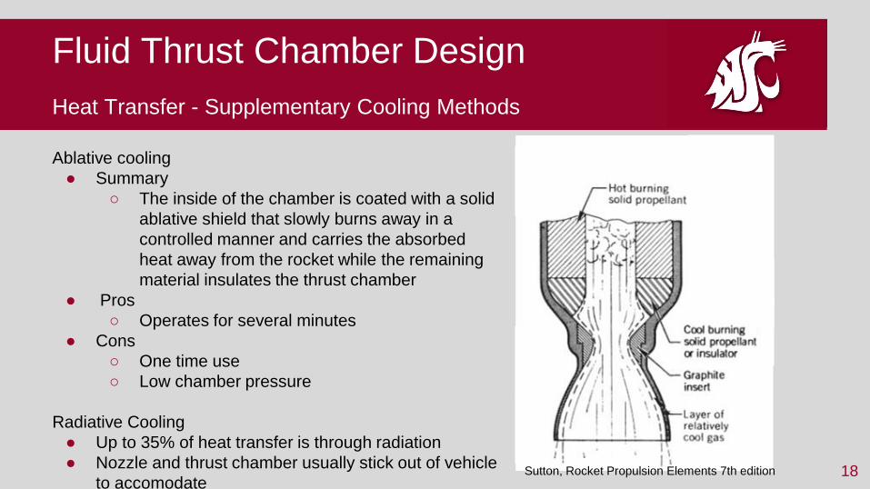
Ablative cooling
● Summary
○ The inside of the chamber is coated with a solid
ablative shield that slowly burns away in a
controlled manner and carries the absorbed
heat away from the rocket while the remaining
material insulates the thrust chamber
● Pros
○ Operates for several minutes
● Cons
○ One time use
○ Low chamber pressure
Radiative Cooling
● Up to 35% of heat transfer is through radiation
● Nozzle and thrust chamber usually stick out of vehicle
to accomodate18
Heat Transfer - Supplementary Cooling Methods
Fluid Thrust Chamber Design
Sutton, Rocket Propulsion Elements 7th edition

Design Decisions
● Best option:
○ Regenerative cooling
○ pending whether or not we can 3D print
■ MTI
● Fallback options
○ Ablative cooling with graphite
○ Film cooling
Heat Transfer - Design
Fluid Thrust Chamber Design
1919http://darshan-earnmoney.blogspot.com/2010/02/rocket.html
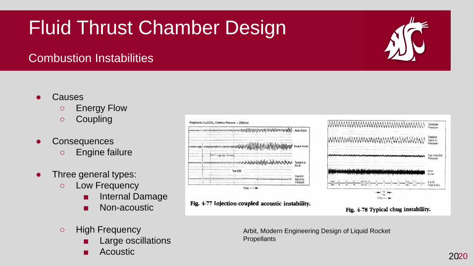
Combustion Instabilities
● Causes
○ Energy Flow
○ Coupling
● Consequences
○ Engine failure
● Three general types:
○ Low Frequency
■ Internal Damage
■ Non-acoustic
○ High Frequency
■ Large oscillations
■ Acoustic
Fluid Thrust Chamber Design
2020
Arbit, Modern Engineering Design of Liquid Rocket
Propellants

Fluid Thrust Chamber Design
General Frequency Equation
● Longitudinal Mode
○ Least severe form
● Tangential Mode
○ Most severe form
● Radial mode
● Optimize for Tangential
21
Arbit, Modern Engineering Design of Liquid Rocket
Propellants

Acoustic Effects
● Intrinsic Acoustic
○ Dependencies
■ Chemical Kinetics
○ Coaxial injectors are best
for preventing effects.
● Video
○ Geometry relates to
acoustics
■ Affects coupling
Fluid Thrust Chamber Design
2222

Fluid Thrust Chamber DesignAvoiding Instabilities/Practicality
● The steps to avoid instabilities require steady state
pressure releases
○ Injectors must have constant heat release rate
● Testing for the oscillations require extensive studies.
○ Model procedures
● Stability Systems
○ Wall Gap
○ Cavities
○ Baffles
2323Arbit, Modern Engineering Design of Liquid Rocket
Propellants

Fluid Thrust Chamber DesignApplication
● Design of the combustion chamber to reduce oscillations
● Injectors should be regulated
● Rocket burn time
○ Experimental evaluation
○ Pressure transducers to check for this
● Account for tangential instabilities
2424

Combustion Chamber
Material Properties for the combustion chamber and nozzle:
● Working Temperature
● Strength at High Temperature
● Oxidation Resistance
● Machinability/Weldability
● Corrosion Resistance
● Thermal Conductivity
Fluid Thrust Chamber Design
2525http://cs.astrium.eads.net/sp/launcher-propulsion/manufacturing/welding-
technologies.html

Combustion Chamber
Material of choice: Superalloy
Superalloy: Alloy that can withstand high temperature, high stresses, and highly
oxidizing environments
Two Types of Superalloys:
● Nickel Based
● Cobalt Based
Nickel Based: More widely used, higher strength, ductility and fracture
toughness
Cobalt Based: Higher oxidation, hot corrosion, and wear resistance
26
Fluid Thrust Chamber Design
http://www.spacex.com/news/2014/07/31/spacex-launches-3d-printed-part-space-creates-printed-engine-chamber-
crewed

Combustion Chamber
Superalloy of choice: Haynes 230
Other Superalloys to consider:
● Haynes 25: Lower Working Temperature (WT) 980 °C
● Inconel 625: Hard to Machine, Lower WT (980 °C)
● Inconel 728: Lower WT than Inconel 625 (700 °C)
● Rene 41: Lower WT (980 °C), Harder to machine than Inconel
Other Material Considerations:
● 3D Printing C-103: Extremely expensive (MTI)
● Graphite: Would have to replace after every use
● Ceramic: Unknown distributor, low ductility
27
Fluid Thrust Chamber Design

Combustion Chamber
Machinability/Weldability
Can be:
● Forged (Cold Worked)
● Hot worked (at 1177 °C)
● Casted
Welding options:
● Gas Metal arc (GMAW)
● Gas Tungsten arc (GTAW)
● Resistance Welding
28
Fluid Thrust Chamber Design
http://www.haynesintl.com/pdf/h3000.pdf (pg. 17)
http://www.haynesintl.com/pdf/h3000.pdf (pg.
19)

Combustion Chamber
Working Temperature
● Working Temperature of at least 1150 °C
● Melting Temperature is 1300 °C
● Chamber Temperatures could be as high
as 2500 °C
Strength at High Temperature
● Chamber pressures may be as high as 2
MPa
29
Fluid Thrust Chamber Design
http://www.haynesintl.com/pdf/h3000.pdf (pg. 9)
SMART Rockets
(http://www.dglr.de/publikationen/2013/301353.pdf)

Summary/Selections
First Choices
● Injector: Coax Element
● Cooling System: Regenerative Cooling
● Thrust Chamber Material: C-103
Secondary Options
● Injector: Like Impinging Doublet
● Cooling System: Ablative Cooling
● Thrust Chamber Material: Haynes 230
Additional Considerations
● Acoustic design configuration
30
Fluid Thrust Chamber Design
https://cvdmaterialstechnology.files.wordpress.com/2013/03/1-s2-0-s0094576504001614-gr1.jpg
http://www.k-
makris.gr/RocketTechnology/ThrustChamber/Thrust_Chamber.htm

Fluid Thrust Chamber Design
Kevin Cavender, Den Donahou, Connor Halliday, Mario Reillo, Marshall Crenshaw
3131

Appendix: Combustion Chamber
Oxidation Resistance
● Mils (thousandths of an inch)
32
Fluid Thrust Chamber Design
http://www.haynesintl.com/pdf/h3000.pdf (pg. 15)

Appendix: Combustion Chamber
Thermal Conductivity
● Important to maintain a lower internal combustion chamber
temperature
Low when compared to softer metals (@ 973.2 K) like:
● Copper: 354 W/m-K
● Aluminum: 92 W/m-K
● Nickel: 71 W/m-K
Comparable to stronger metals (@ 973.2 K) like:
● Carbon Steels: ~30 W/m-K
● Low Alloy Steels: ~30 W/m-K
● Stainless Steels: ~24 W/m-K
● High Alloy Steels: ~23 W/m-K
33
Fluid Thrust Chamber Design
http://www.haynesintl.com/pdf/h3000.pdf (pg. 12)


