Advanced Steel Construction Vol. 5, No. 3, pp. 325-342 (2009) 325 FLUID VISCOUS DAMPER-BASED SEISMIC RETROFIT STRATEGIES OF STEEL STRUCTURES: GENERAL CONCEPTS AND DESIGN APPLICATIONS Stefano Sorace 1,* and Gloria Terenzi 2 1 Department of Civil Engineering and Architecture, University of Udine Via delle Scienze 208, 33100 Udine, Italy 2 Department of Civil and Environmental Engineering, University of Florence Via S. Marta 3, 50139 Florence, Italy * (Corresponding author: Phone: +39 432 558050; Fax: +39 432 558052; E-mail: [email protected]) Received: 29 April 2008; Accepted: 2 May 2008 ABSTRACT: Two advanced seismic protection technologies, represented by a dissipative bracing system and a damped cable system, both incorporating fluid viscous dampers as passive control devices, are examined with special reference to their use in retrofitting steel structures. The essential characteristics and performance of the dampers and the two technologies, along with their analytical and computational modelling criteria, are recalled in the first part of this paper. A demonstrative design study concerning the application of both systems to an Italian pre-normative steel school building is then presented, by discussing the mechanical parameters, dimensions, layouts and locations selected for the relevant constituting elements. The advantages of the two rehabilitation hypotheses are assessed in terms of the mutual performance objectives formulated at a preliminary design stage, based on the results of the modal and non-linear dynamic analyses carried out during the final verification phase. Structural implementation and technical installation details are finally provided for both retrofit solutions. Keywords: Steel structures; advanced seismic protection; seismic retrofit; damping; fluid viscous dampers; dissipative bracing; damped cables 1. INTRODUCTION A great number of steel buildings were designed in European earthquake-prone countries throughout the Sixties and early Seventies without any seismic provisions, due to the lack of reference Technical Standards at that time. In the past few years, a new public policy aimed at a seismic evaluation and retrofit of this stock of potentially unsafe structures was started, so as to improve their seismic performance substantially. These retrofit interventions are still generally based on conventional solutions for rehabilitation and strengthening (e.g., addition of reinforced concrete walls and/or traditional steel bracing systems, extensive enlargement of columns and beams, jacketing, etc). As an alternative, supplemental energy dissipation-based seismic protection strategies were recently adopted [1-3], by extending to steel structures the advanced technologies already applied to pre-normative reinforced concrete buildings. Two special technologies belonging to this class, and namely a dissipative bracing (DB) system and a “damped cable” (DC) system, which incorporate pressurized silicone fluid viscous (FV) spring-dampers as protective devices, have been studied by the authors of this paper for several years. Numerical and analytical modelling; experimental characterization and verification; definition of design procedures; and technical implementation of the two technologies, were particularly developed within these research activities [4-9dissipative braces; 10, 11, 7damped cables]. The essential aspects of these studies, which paved the way for a practical use of both systems in the field of seismic retrofit of frame structures, are summarized in the following three sections of this paper. Then, two retrofit hypotheses of an Italian school buildingwell representative of the above-mentioned stock of pre-normative steel structuresare offered as demonstrative potential applications of the two rehabilitation strategies. A synthesis of the preliminary design structural analyses carried out on both systems, as well as of their best-location The Hong Kong Institute of Steel Construction www.hkisc.org
Transcript
Advanced Steel Construction Vol. 5, No. 3, pp. 325-342 (2009) 325
FLUID VISCOUS DAMPER-BASED SEISMIC RETROFIT STRATEGIES OF STEEL STRUCTURES:
GENERAL CONCEPTS AND DESIGN APPLICATIONS
Stefano Sorace 1,* and Gloria Terenzi 2
1 Department of Civil Engineering and Architecture, University of Udine Via delle Scienze 208, 33100 Udine, Italy
2 Department of Civil and Environmental Engineering, University of Florence Via S. Marta 3, 50139 Florence, Italy
ABSTRACT: Two advanced seismic protection technologies, represented by a dissipative bracing system and a damped cable system, both incorporating fluid viscous dampers as passive control devices, are examined with special reference to their use in retrofitting steel structures. The essential characteristics and performance of the dampers and the two technologies, along with their analytical and computational modelling criteria, are recalled in the first part of this paper. A demonstrative design study concerning the application of both systems to an Italian pre-normative steel school building is then presented, by discussing the mechanical parameters, dimensions, layouts and locations selected for the relevant constituting elements. The advantages of the two rehabilitation hypotheses are assessed in terms of the mutual performance objectives formulated at a preliminary design stage, based on the results of the modal and non-linear dynamic analyses carried out during the final verification phase. Structural implementation and technical installation details are finally provided for both retrofit solutions.
1. INTRODUCTION A great number of steel buildings were designed in European earthquake-prone countries throughout the Sixties and early Seventies without any seismic provisions, due to the lack of reference Technical Standards at that time. In the past few years, a new public policy aimed at a seismic evaluation and retrofit of this stock of potentially unsafe structures was started, so as to improve their seismic performance substantially. These retrofit interventions are still generally based on conventional solutions for rehabilitation and strengthening (e.g., addition of reinforced concrete walls and/or traditional steel bracing systems, extensive enlargement of columns and beams, jacketing, etc). As an alternative, supplemental energy dissipation-based seismic protection strategies were recently adopted [1-3], by extending to steel structures the advanced technologies already applied to pre-normative reinforced concrete buildings. Two special technologies belonging to this class, and namely a dissipative bracing (DB) system and a “damped cable” (DC) system, which incorporate pressurized silicone fluid viscous (FV) spring-dampers as protective devices, have been studied by the authors of this paper for several years. Numerical and analytical modelling; experimental characterization and verification; definition of design procedures; and technical implementation of the two technologies, were particularly developed within these research activities [4-9dissipative braces; 10, 11, 7damped cables]. The essential aspects of these studies, which paved the way for a practical use of both systems in the field of seismic retrofit of frame structures, are summarized in the following three sections of this paper. Then, two retrofit hypotheses of an Italian school buildingwell representative of the above-mentioned stock of pre-normative steel structuresare offered as demonstrative potential applications of the two rehabilitation strategies. A synthesis of the preliminary design structural analyses carried out on both systems, as well as of their best-location
The Hong Kong Institute of Steel Construction www.hkisc.org
326 Fluid Viscous Damper-Based Seismic Retrofit Strategies of Steel Structures: General Concepts and Design Applications
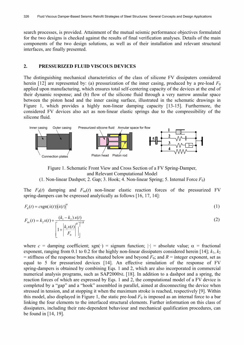
search processes, is provided. Attainment of the mutual seismic performance objectives formulated for the two designs is checked against the results of final verification analyses. Details of the main components of the two design solutions, as well as of their installation and relevant structural interfaces, are finally presented. 2. PRESSURIZED FLUID VISCOUS DEVICES The distinguishing mechanical characteristics of the class of silicone FV dissipaters considered herein [12] are represented by: (a) pressurization of the inner casing, produced by a pre-load F0 applied upon manufacturing, which ensures total self-centering capacity of the devices at the end of their dynamic response; and (b) flow of the silicone fluid through a very narrow annular space between the piston head and the inner casing surface, illustrated in the schematic drawings in Figure 1, which provides a highly non-linear damping capacity [13-15]. Furthermore, the considered FV devices also act as non-linear elastic springs due to the compressibility of the silicone fluid.
Figure 1. Schematic Front View and Cross Section of a FV Spring-Damper, and Relevant Computational Model
(1. Non-linear Dashpot; 2. Gap; 3. Hook; 4. Non-linear Spring; 5. Internal Force F0) The Fd(t) damping and Fne(t) non-linear elastic reaction forces of the pressurized FV spring-dampers can be expressed analytically as follows [16, 17, 14]:
)())(sgn()(d txtxctF (1)
RR
F
txk
txkktxktF /1
0
1
212ne
)(1
)()()()(
(2)
where c = damping coefficient; sgn(·) = signum function; |·| = absolute value; = fractional exponent, ranging from 0.1 to 0.2 for the highly non-linear dissipaters considered herein [14]; k1, k2 = stiffness of the response branches situated below and beyond F0; and R = integer exponent, set as equal to 5 for pressurized devices [14]. An effective simulation of the response of FV spring-dampers is obtained by combining Eqs. 1 and 2, which are also incorporated in commercial numerical analysis programs, such as SAP2000NL [18]. In addition to a dashpot and a spring, the reaction forces of which are expressed by Eqs. 1 and 2, the computational model of a FV device is completed by a “gap” and a “hook” assembled in parallel, aimed at disconnecting the device when stressed in tension, and at stopping it when the maximum stroke is reached, respectively [9]. Within this model, also displayed in Figure 1, the static pre-load F0 is imposed as an internal force to a bar linking the four elements to the interfaced structural elements. Further information on this class of dissipaters, including their rate-dependent behaviour and mechanical qualification procedures, can be found in [14, 19].
3. DISSIPATIVE BRACING SYSTEM A typical design drawing of a FV spring-dampersbracesbeam connection of the DB system is illustrated in Figure 2, showing that the devices are installed, in parallel with the floor beam, at the tip of each couple of supporting steel braces. A half-stroke initial position is imposed to the pistons of both spring-dampers, so as to obtain symmetrical tension-compression response cycles, starting from a compressive-only response of the single devices. This position is obtained by introducing a pair of threaded steel bars through a central bored plate orthogonal to the interfacing plate of the two devices; the bars are connected at both ends to other two bored plates, threaded into the external casing of the spring-dampers. The axial force required to drive the pistons at their half-strokes is applied to the steel bars by a torque wrench, by acting on the nuts in contact with the two plates threaded on the devices. The terminal section of the external casing of each FV device is encapsulated into a steel “cap” hinged to two vertical trapezoidal plates welded to the upper horizontal plate of the assembly, which is fixed to the lower face of the floor beam. The caps constrain the spring-dampers to move with the same displacement as the floor beam. Thanks to the rigid support offered by the diagonal braces, mounted in an inverse-chevron configuration, this installation helps the devices exploit the entire interstory drift between the upper and lower floor across which they are placed. In order to prevent out-of-plane displacements of the DB system, two small protection plates are mounted in parallel to the vertical plate interfacing the devices, at 1 mm distance from its faces. A Teflon disk is placed on the inner faces of the protection plates, to avoid any frictional effects in case of accidental contact with the interfacing plate during seismic response.
Figure 2. Drawing of a FV Spring-DamperBracesBeam Connection in a DB System
It can be observed that the tip installation of the FV devices over the supporting braces neutralizes the stiffening effects of the latter on the frame structure as soon as the static pre-load F0 is exceeded. Indeed, beyond this threshold, the devices react with their low second-branch spring stiffness k2. Owing to the in-series connection of FV devices and braces, this produces a limited global stiffness of the DB system, as compared to the one of the original frame structure. This avoids an undesired increase of spectral accelerations—and thus of story forces and shears—associated to the high stiffening effects typically induced by the installation of conventional undamped braces, as well as of dissipative technologies where dampers are installed in parallel with the diagonal braces. Extensive experimental activities were carried out on the DB technology [5, 6, 8, 9], with a view to studying its practical application to the rehabilitation of steel and reinforced concrete buildings. They evidenced that high seismic performance levels of the tested structures are always attained after retrofit. Moreover, the experiments allowed developing a thorough calibration of the formulated analytical and numerical models, as well as of the proposed design methodology of the DB system [5, 9].
Threaded steel bar FV spring-dampers
Out-of-plane protection plate
Connection capHinge
Interfacing plate
328 Fluid Viscous Damper-Based Seismic Retrofit Strategies of Steel Structures: General Concepts and Design Applications
Floor deviators
FV spring-damper Pre-stressed cable
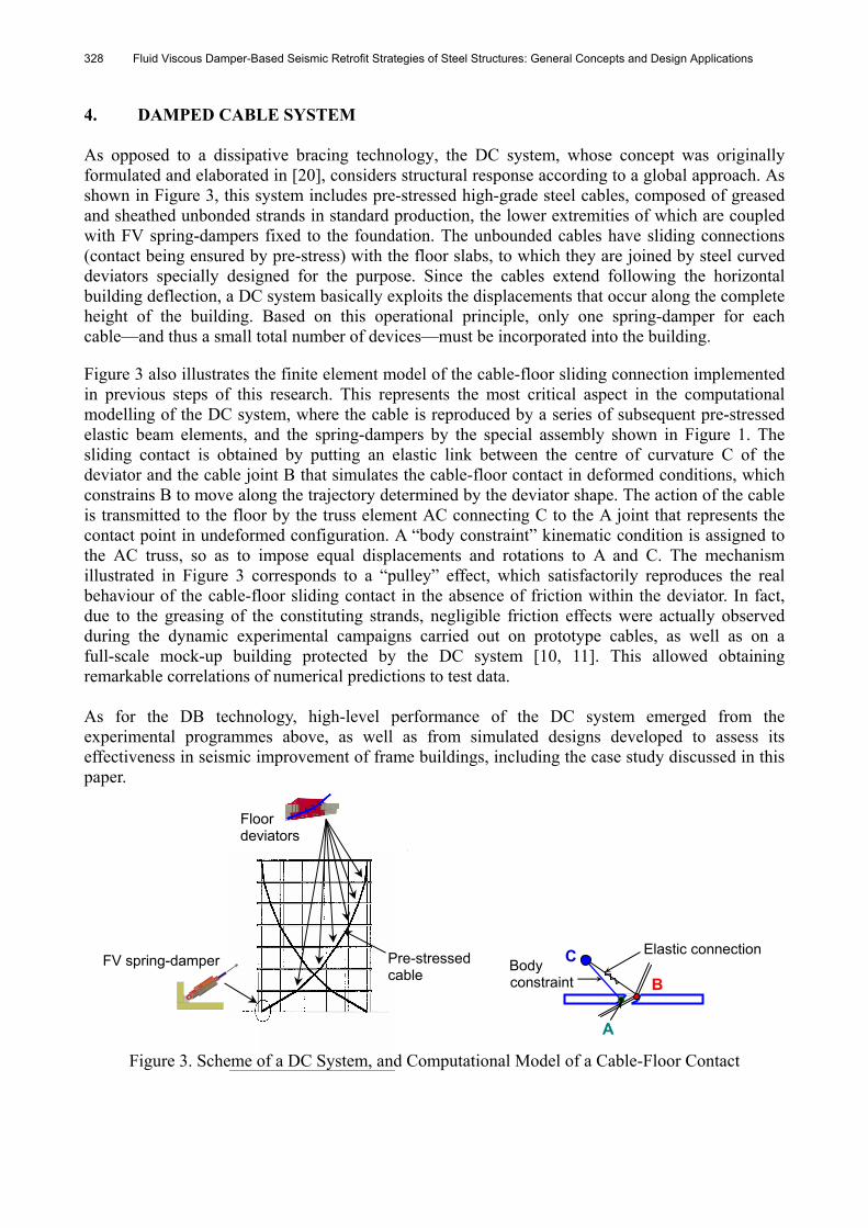
4. DAMPED CABLE SYSTEM As opposed to a dissipative bracing technology, the DC system, whose concept was originally formulated and elaborated in [20], considers structural response according to a global approach. As shown in Figure 3, this system includes pre-stressed high-grade steel cables, composed of greased and sheathed unbonded strands in standard production, the lower extremities of which are coupled with FV spring-dampers fixed to the foundation. The unbounded cables have sliding connections (contact being ensured by pre-stress) with the floor slabs, to which they are joined by steel curved deviators specially designed for the purpose. Since the cables extend following the horizontal building deflection, a DC system basically exploits the displacements that occur along the complete height of the building. Based on this operational principle, only one spring-damper for each cable—and thus a small total number of devices—must be incorporated into the building. Figure 3 also illustrates the finite element model of the cable-floor sliding connection implemented in previous steps of this research. This represents the most critical aspect in the computational modelling of the DC system, where the cable is reproduced by a series of subsequent pre-stressed elastic beam elements, and the spring-dampers by the special assembly shown in Figure 1. The sliding contact is obtained by putting an elastic link between the centre of curvature C of the deviator and the cable joint B that simulates the cable-floor contact in deformed conditions, which constrains B to move along the trajectory determined by the deviator shape. The action of the cable is transmitted to the floor by the truss element AC connecting C to the A joint that represents the contact point in undeformed configuration. A “body constraint” kinematic condition is assigned to the AC truss, so as to impose equal displacements and rotations to A and C. The mechanism illustrated in Figure 3 corresponds to a “pulley” effect, which satisfactorily reproduces the real behaviour of the cable-floor sliding contact in the absence of friction within the deviator. In fact, due to the greasing of the constituting strands, negligible friction effects were actually observed during the dynamic experimental campaigns carried out on prototype cables, as well as on a full-scale mock-up building protected by the DC system [10, 11]. This allowed obtaining remarkable correlations of numerical predictions to test data. As for the DB technology, high-level performance of the DC system emerged from the experimental programmes above, as well as from simulated designs developed to assess its effectiveness in seismic improvement of frame buildings, including the case study discussed in this paper.
Figure 3. Scheme of a DC System, and Computational Model of a Cable-Floor Contact
Body constraint
Elastic connectionC
A
B
Stefano Sorace and Gloria Terenzi 329
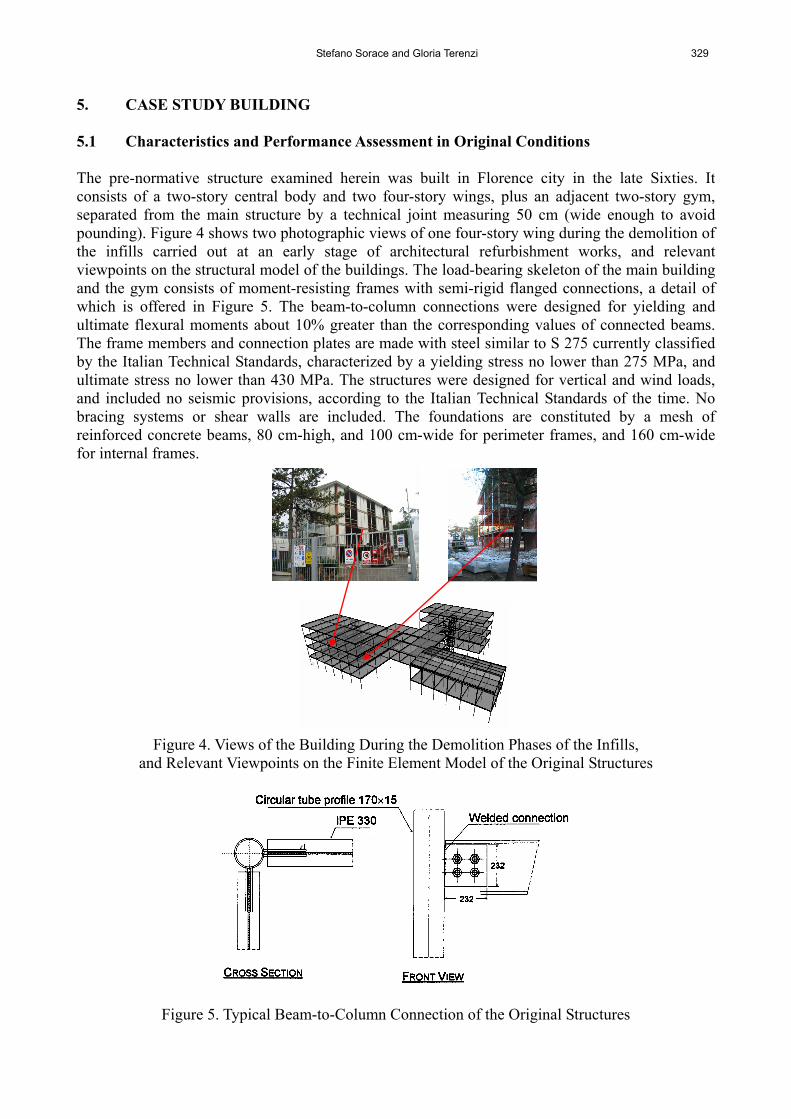
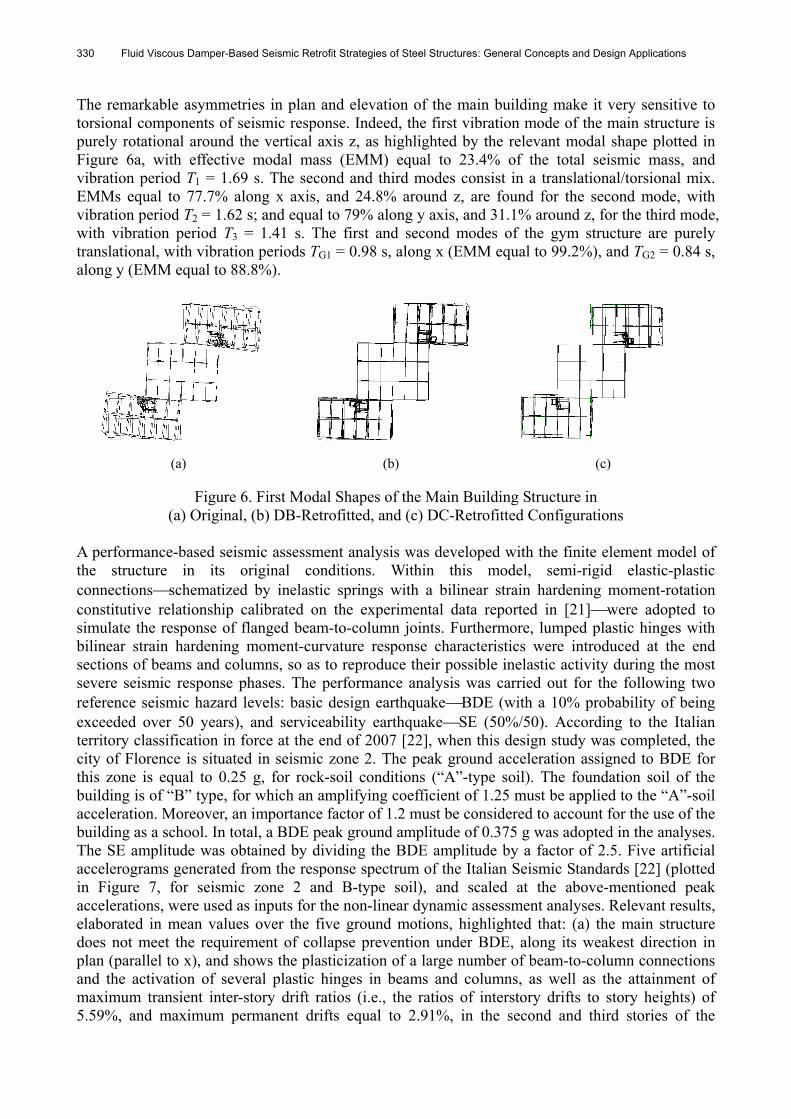
5. CASE STUDY BUILDING 5.1 Characteristics and Performance Assessment in Original Conditions The pre-normative structure examined herein was built in Florence city in the late Sixties. It consists of a two-story central body and two four-story wings, plus an adjacent two-story gym, separated from the main structure by a technical joint measuring 50 cm (wide enough to avoid pounding). Figure 4 shows two photographic views of one four-story wing during the demolition of the infills carried out at an early stage of architectural refurbishment works, and relevant viewpoints on the structural model of the buildings. The load-bearing skeleton of the main building and the gym consists of moment-resisting frames with semi-rigid flanged connections, a detail of which is offered in Figure 5. The beam-to-column connections were designed for yielding and ultimate flexural moments about 10% greater than the corresponding values of connected beams. The frame members and connection plates are made with steel similar to S 275 currently classified by the Italian Technical Standards, characterized by a yielding stress no lower than 275 MPa, and ultimate stress no lower than 430 MPa. The structures were designed for vertical and wind loads, and included no seismic provisions, according to the Italian Technical Standards of the time. No bracing systems or shear walls are included. The foundations are constituted by a mesh of reinforced concrete beams, 80 cm-high, and 100 cm-wide for perimeter frames, and 160 cm-wide for internal frames.
Figure 4. Views of the Building During the Demolition Phases of the Infills, and Relevant Viewpoints on the Finite Element Model of the Original Structures
Figure 5. Typical Beam-to-Column Connection of the Original Structures
330 Fluid Viscous Damper-Based Seismic Retrofit Strategies of Steel Structures: General Concepts and Design Applications
The remarkable asymmetries in plan and elevation of the main building make it very sensitive to torsional components of seismic response. Indeed, the first vibration mode of the main structure is purely rotational around the vertical axis z, as highlighted by the relevant modal shape plotted in Figure 6a, with effective modal mass (EMM) equal to 23.4% of the total seismic mass, and vibration period T1 = 1.69 s. The second and third modes consist in a translational/torsional mix. EMMs equal to 77.7% along x axis, and 24.8% around z, are found for the second mode, with vibration period T2 = 1.62 s; and equal to 79% along y axis, and 31.1% around z, for the third mode, with vibration period T3 = 1.41 s. The first and second modes of the gym structure are purely translational, with vibration periods TG1 = 0.98 s, along x (EMM equal to 99.2%), and TG2 = 0.84 s, along y (EMM equal to 88.8%).
(a) (b) (c)
Figure 6. First Modal Shapes of the Main Building Structure in (a) Original, (b) DB-Retrofitted, and (c) DC-Retrofitted Configurations
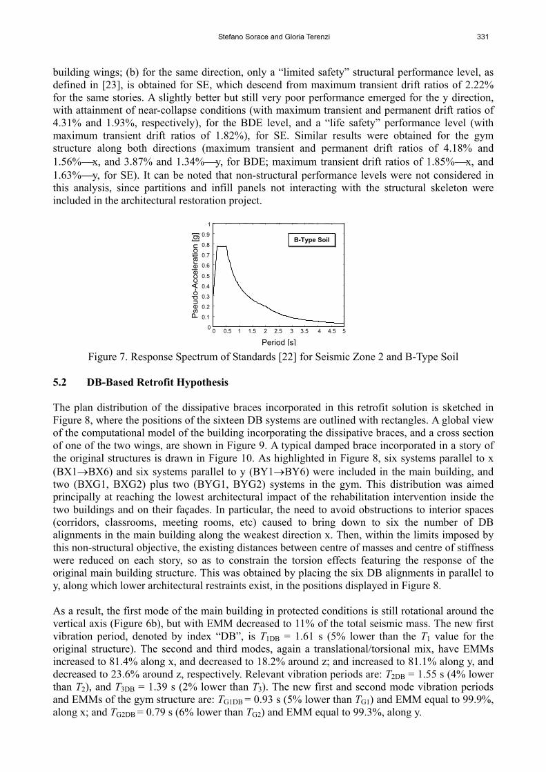
A performance-based seismic assessment analysis was developed with the finite element model of the structure in its original conditions. Within this model, semi-rigid elastic-plastic connectionsschematized by inelastic springs with a bilinear strain hardening moment-rotation constitutive relationship calibrated on the experimental data reported in [21]were adopted to simulate the response of flanged beam-to-column joints. Furthermore, lumped plastic hinges with bilinear strain hardening moment-curvature response characteristics were introduced at the end sections of beams and columns, so as to reproduce their possible inelastic activity during the most severe seismic response phases. The performance analysis was carried out for the following two reference seismic hazard levels: basic design earthquakeBDE (with a 10% probability of being exceeded over 50 years), and serviceability earthquakeSE (50%/50). According to the Italian territory classification in force at the end of 2007 [22], when this design study was completed, the city of Florence is situated in seismic zone 2. The peak ground acceleration assigned to BDE for this zone is equal to 0.25 g, for rock-soil conditions (“A”-type soil). The foundation soil of the building is of “B” type, for which an amplifying coefficient of 1.25 must be applied to the “A”-soil acceleration. Moreover, an importance factor of 1.2 must be considered to account for the use of the building as a school. In total, a BDE peak ground amplitude of 0.375 g was adopted in the analyses. The SE amplitude was obtained by dividing the BDE amplitude by a factor of 2.5. Five artificial accelerograms generated from the response spectrum of the Italian Seismic Standards [22] (plotted in Figure 7, for seismic zone 2 and B-type soil), and scaled at the above-mentioned peak accelerations, were used as inputs for the non-linear dynamic assessment analyses. Relevant results, elaborated in mean values over the five ground motions, highlighted that: (a) the main structure does not meet the requirement of collapse prevention under BDE, along its weakest direction in plan (parallel to x), and shows the plasticization of a large number of beam-to-column connections and the activation of several plastic hinges in beams and columns, as well as the attainment of maximum transient inter-story drift ratios (i.e., the ratios of interstory drifts to story heights) of 5.59%, and maximum permanent drifts equal to 2.91%, in the second and third stories of the
Stefano Sorace and Gloria Terenzi 331
building wings; (b) for the same direction, only a “limited safety” structural performance level, as defined in [23], is obtained for SE, which descend from maximum transient drift ratios of 2.22% for the same stories. A slightly better but still very poor performance emerged for the y direction, with attainment of near-collapse conditions (with maximum transient and permanent drift ratios of 4.31% and 1.93%, respectively), for the BDE level, and a “life safety” performance level (with maximum transient drift ratios of 1.82%), for SE. Similar results were obtained for the gym structure along both directions (maximum transient and permanent drift ratios of 4.18% and 1.56%x, and 3.87% and 1.34%y, for BDE; maximum transient drift ratios of 1.85%x, and 1.63%y, for SE). It can be noted that non-structural performance levels were not considered in this analysis, since partitions and infill panels not interacting with the structural skeleton were included in the architectural restoration project.
Figure 7. Response Spectrum of Standards [22] for Seismic Zone 2 and B-Type Soil 5.2 DB-Based Retrofit Hypothesis The plan distribution of the dissipative braces incorporated in this retrofit solution is sketched in Figure 8, where the positions of the sixteen DB systems are outlined with rectangles. A global view of the computational model of the building incorporating the dissipative braces, and a cross section of one of the two wings, are shown in Figure 9. A typical damped brace incorporated in a story of the original structures is drawn in Figure 10. As highlighted in Figure 8, six systems parallel to x (BX1BX6) and six systems parallel to y (BY1BY6) were included in the main building, and two (BXG1, BXG2) plus two (BYG1, BYG2) systems in the gym. This distribution was aimed principally at reaching the lowest architectural impact of the rehabilitation intervention inside the two buildings and on their façades. In particular, the need to avoid obstructions to interior spaces (corridors, classrooms, meeting rooms, etc) caused to bring down to six the number of DB alignments in the main building along the weakest direction x. Then, within the limits imposed by this non-structural objective, the existing distances between centre of masses and centre of stiffness were reduced on each story, so as to constrain the torsion effects featuring the response of the original main building structure. This was obtained by placing the six DB alignments in parallel to y, along which lower architectural restraints exist, in the positions displayed in Figure 8. As a result, the first mode of the main building in protected conditions is still rotational around the vertical axis (Figure 6b), but with EMM decreased to 11% of the total seismic mass. The new first vibration period, denoted by index “DB”, is T1DB = 1.61 s (5% lower than the T1 value for the original structure). The second and third modes, again a translational/torsional mix, have EMMs increased to 81.4% along x, and decreased to 18.2% around z; and increased to 81.1% along y, and decreased to 23.6% around z, respectively. Relevant vibration periods are: T2DB = 1.55 s (4% lower than T2), and T3DB = 1.39 s (2% lower than T3). The new first and second mode vibration periods and EMMs of the gym structure are: TG1DB = 0.93 s (5% lower than TG1) and EMM equal to 99.9%, along x; and TG2DB = 0.79 s (6% lower than TG2) and EMM equal to 99.3%, along y.
0 0.5 1 1.5 2 2.5 3 3.5 4 4.5 5 0
0.1
0.2
0.3
0.4
0.5
0.6
0.7
0.8
0.9
1
Period [s]
Pse
udo
-Acc
ele
ratio
n [g
]
B-Type Soil
332 Fluid Viscous Damper-Based Seismic Retrofit Strategies of Steel Structures: General Concepts and Design Applications
The performance objectives of this retrofit hypothesis, as well as of the one based on the use of the DC technology, consisted in reaching, for the main building and the gym: (1) a “damage control” level for BDE, with at most some slight plasticizations in few beams, and 1.5% maximum interstory drift ratios; (2) “immediate occupancy” for SE, with an elastic response of all frame members, and 0.7% maximum drift ratios. The FV spring-dampers were selected by means of the energy-based design method discussed in [5, 9], which is briefly recalled below. The damping coefficient of the devices is selected by assigning them the capability of dissipating a prefixed fraction of the total seismic input energy computed for the structure on each story. This condition is expressed as follows
jjjβ
IDEE (3)
where j is the imposed energy fraction for the j-th story; ct
D dtvvsgnvcE0
jj
α
jtjj )( is the energy
dissipated in the j-th story by the set of spring-dampers placed on that story, with tc = instant at which the j-th story reaches the maximum interstory drift, ctj = global damping coefficient characterizing the j-th story spring-dampers, jv = relative velocity of the j-th story; and
g
t
tI dvvmE c
0
jjj is the “absolute” input energy [24] of the j-th story, where mj = mass associated to
the j-th story, jtv = absolute j-th story acceleration, and vg = ground displacement. The method
starts from an initial choice of the set of j values governing (3), to be calibrated on the targeted reduction of interstory drift in protected conditions, for the BDE seismic level. Detailed criteria to perform this selection are presented in [9]. According to these criteria and considering that, based on the retrofit objectives postulated above, the target BDE-related drift reductions are equal to around 4, j values of 0.5 were selected for the most stressed stories, represented by the second and third ones of the main building. Moreover, following the suggestions reported in [9] again, j values multiplied by factors 0.8 and 0.4 were adopted for the first and fourth story, respectively, to account for the lower drift demands characterizing these levels. To summarize, the following set of j values was assumed for the main building: 1 = 0.4, 2 = 3 = 0.5, and 4 = 0.2. A mutual j = 1 = 2 value of 0.5 was fixed for the two-story gym. Based on these energy fraction coefficients, an iterative search process was developed to locate the relevant set of ctj values satisfying equation (3). This process helped identify the following rounded values of the damping coefficient of each device placed in the main building: c = 24 kN(s/m) (with = 0.15) at the first story, c = 30 kN(s/m) at the second and third story, and c = 16 kN(s/m) at the fourth story—x direction; and c = 20 kN(s/m) at the first story, c = 24 kN(s/m) at the second and third story, and c = 14 kN(s/m) at the fourth story—y direction. The rounded c values found for the gym were, for both axes: c = 16 kN(s/m) (first story), and c = 24 kN(s/m) (second story). The currently available FV spring-damper that is capable of supplying these damping demands and, at the same time, has a greater stroke than the maximum BDE-related drifts in protected conditions (as discussed in the next section), is characterized by the following mechanical properties [12]: nominal energy dissipation capacity En equal to 7 kJ, F0 = 18 kN, stroke dmax equal to 100 mm (50 mm in the half-stroke initial position required by the DB system installation), and maximum attainable damping coefficient cmax = 39 kN(s/m). It can be noted that the different c values listed above are obtained, within the cmax limit, by imposing upon manufacturing different openings of the annular space between piston head and inner casing surface. The selected type of device represents the final design choice for this retrofit hypothesis. As bracing elements of the system, double UPN
Stefano Sorace and Gloria Terenzi 333
160 European standard channel profiles were adopted for the three lower stories of the main building, and double UPN 120 profiles for the upper story, in both directions; and double UPN 160 profiles in both directions and on both stories of the gym building.
Figure 8. Plan Distribution of the DBs included in the Relevant Retrofit Hypothesis
Figure 9. Global View of the Finite Element Model of the DB-Retrofitted Main Building Structure,
and Cross Section Over a Four-Story Wing
Figure 10. Global and Zoomed Views of a Typical Damped Brace
X Y
BX1
BX2 BX3
BXG1
BX4 BX5
BYG1
BXG2BX6
BY3 BY2 BY3
BY4 BY5 BY6
BYG2
334 Fluid Viscous Damper-Based Seismic Retrofit Strategies of Steel Structures: General Concepts and Design Applications
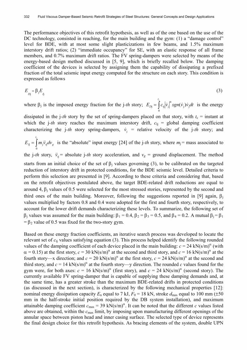
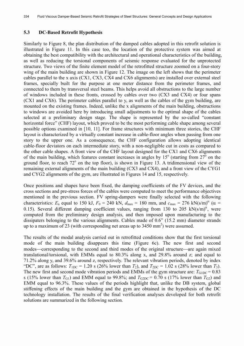
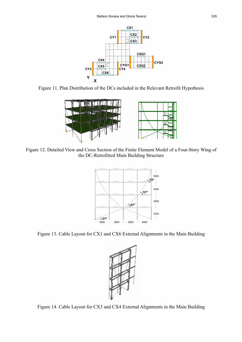
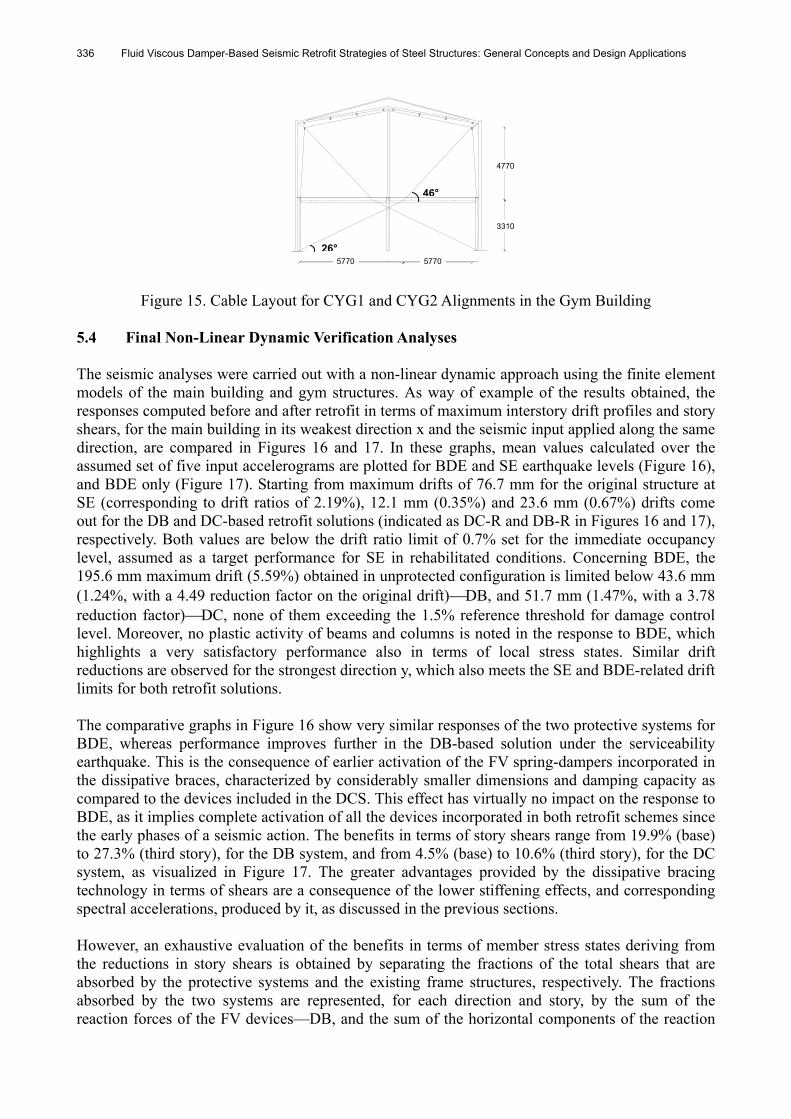
5.3 DC-Based Retrofit Hypothesis Similarly to Figure 8, the plan distribution of the damped cables adopted in this retrofit solution is illustrated in Figure 11. In this case too, the location of the protective system was aimed at obtaining the best compatibility with the architectural and operational characteristics of the building, as well as reducing the torsional components of seismic response evaluated for the unprotected structure. Two views of the finite element model of the retrofitted structure zoomed on a four-story wing of the main building are shown in Figure 12. The image on the left shows that the perimeter cables parallel to the x axis (CX1, CX3, CX4 and CX6 alignments) are installed over external steel frames, specially built for the purpose at one meter distance from the perimeter frames, and connected to them by transversal steel beams. This helps avoid all obstructions to the large number of windows included in these fronts, crossed by cables over two (CX3 and CX4) or four spans (CX1 and CX6). The perimeter cables parallel to y, as well as the cables of the gym building, are mounted on the existing frames. Indeed, unlike the x alignments of the main building, obstructions to windows are avoided here by introducing small adjustments to the optimal shape of the cables selected at a preliminary design stage. The shape is represented by the so-called “constant horizontal force” (CHF) layout, which proved to be the most performing cable shape among several possible options examined in [10, 11]. For frame structures with minimum three stories, the CHF layout is characterized by a virtually constant increase in cable-floor angles when passing from one story to the upper one. As a consequence, the CHF configuration allows adopting identical cable-floor deviators on each intermediate story, with a non-negligible cut in costs as compared to the other cable shapes. A front view of the CHF layout designed for the CX1 and CX6 alignments of the main building, which features constant increases in angles by 15o (starting from 27o on the ground floor, to reach 72o on the top floor), is shown in Figure 13. A tridimensional view of the remaining external alignments of the main building (CX3 and CX4), and a front view of the CYG1 and CYG2 alignments of the gym, are illustrated in Figures 14 and 15, respectively. Once positions and shapes have been fixed, the damping coefficients of the FV devices, and the cross sections and pre-stress forces of the cables were computed to meet the performance objectives mentioned in the previous section. FV spring-dampers were finally selected with the following characteristics: En equal to 150 kJ, F0 = 240 kN, dmax = 180 mm, and cmax = 276 kN(s/m) ( = 0.15). Several different damping coefficient values, ranging from 130 to 205 kN(s/m), were computed from the preliminary design analysis, and then imposed upon manufacturing to the dissipaters belonging to the various alignments. Cables made of 0.6” (15.2 mm) diameter strands up to a maximum of 23 (with corresponding net areas up to 3450 mm2) were assumed. The results of the modal analysis carried out in retrofitted conditions show that the first torsional mode of the main building disappears this time (Figure 6c). The new first and second modescorresponding to the second and third modes of the original structureare again mixed translational/torsional, with EMMs equal to 80.3% along x, and 29.8% around z; and equal to 71.2% along y, and 39.6% around z, respectively. The relevant vibration periods, denoted by index “DC”, are as follows: T1DC = 1.20 s (26% lower than T2), and T2DC = 1.02 s (28% lower than T3). The new first and second mode vibration periods and EMMs of the gym structure are: TG1DC = 0.83 s (15% lower than TG1) and EMM equal to 99.8%; and TG2DC = 0.70 s (17% lower than TG2) and EMM equal to 96.3%. These values of the periods highlight that, unlike the DB system, global stiffening effects of the main building and the gym are obtained in the hypothesis of the DC technology installation. The results of the final verification analyses developed for both retrofit solutions are summarized in the following section.
Stefano Sorace and Gloria Terenzi 335
Figure 11. Plan Distribution of the DCs included in the Relevant Retrofit Hypothesis Figure 12. Detailed View and Cross Section of the Finite Element Model of a Four-Story Wing of
the DC-Retrofitted Main Building Structure
Figure 13. Cable Layout for CX1 and CX6 External Alignments in the Main Building
Figure 14. Cable Layout for CX3 and CX4 External Alignments in the Main Building
CX2
CX3
CX4
CX5
CX6
CXG2CYG1
CY1 CY2
CY3 CY4
CX1
CXG1
CYG2
X Y
350
390390 390390
332
350
350
72°
57°
42°
27°3900 3900 3900 3900
3320
3500
3500
3500
3500
336 Fluid Viscous Damper-Based Seismic Retrofit Strategies of Steel Structures: General Concepts and Design Applications
477
454
331
689
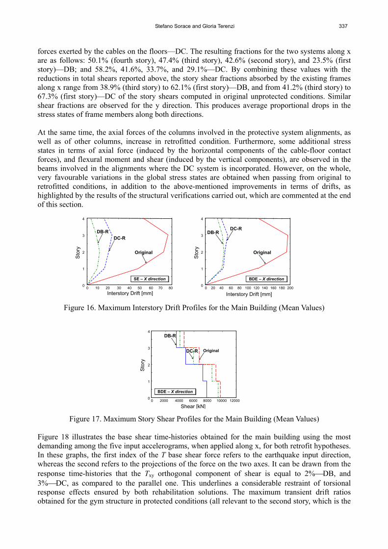
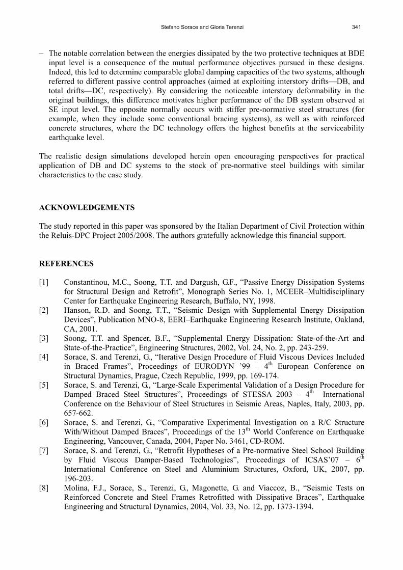
Figure 15. Cable Layout for CYG1 and CYG2 Alignments in the Gym Building 5.4 Final Non-Linear Dynamic Verification Analyses The seismic analyses were carried out with a non-linear dynamic approach using the finite element models of the main building and gym structures. As way of example of the results obtained, the responses computed before and after retrofit in terms of maximum interstory drift profiles and story shears, for the main building in its weakest direction x and the seismic input applied along the same direction, are compared in Figures 16 and 17. In these graphs, mean values calculated over the assumed set of five input accelerograms are plotted for BDE and SE earthquake levels (Figure 16), and BDE only (Figure 17). Starting from maximum drifts of 76.7 mm for the original structure at SE (corresponding to drift ratios of 2.19%), 12.1 mm (0.35%) and 23.6 mm (0.67%) drifts come out for the DB and DC-based retrofit solutions (indicated as DC-R and DB-R in Figures 16 and 17), respectively. Both values are below the drift ratio limit of 0.7% set for the immediate occupancy level, assumed as a target performance for SE in rehabilitated conditions. Concerning BDE, the 195.6 mm maximum drift (5.59%) obtained in unprotected configuration is limited below 43.6 mm (1.24%, with a 4.49 reduction factor on the original drift)DB, and 51.7 mm (1.47%, with a 3.78 reduction factor)DC, none of them exceeding the 1.5% reference threshold for damage control level. Moreover, no plastic activity of beams and columns is noted in the response to BDE, which highlights a very satisfactory performance also in terms of local stress states. Similar drift reductions are observed for the strongest direction y, which also meets the SE and BDE-related drift limits for both retrofit solutions. The comparative graphs in Figure 16 show very similar responses of the two protective systems for BDE, whereas performance improves further in the DB-based solution under the serviceability earthquake. This is the consequence of earlier activation of the FV spring-dampers incorporated in the dissipative braces, characterized by considerably smaller dimensions and damping capacity as compared to the devices included in the DCS. This effect has virtually no impact on the response to BDE, as it implies complete activation of all the devices incorporated in both retrofit schemes since the early phases of a seismic action. The benefits in terms of story shears range from 19.9% (base) to 27.3% (third story), for the DB system, and from 4.5% (base) to 10.6% (third story), for the DC system, as visualized in Figure 17. The greater advantages provided by the dissipative bracing technology in terms of shears are a consequence of the lower stiffening effects, and corresponding spectral accelerations, produced by it, as discussed in the previous sections. However, an exhaustive evaluation of the benefits in terms of member stress states deriving from the reductions in story shears is obtained by separating the fractions of the total shears that are absorbed by the protective systems and the existing frame structures, respectively. The fractions absorbed by the two systems are represented, for each direction and story, by the sum of the reaction forces of the FV devices—DB, and the sum of the horizontal components of the reaction
3310
4770
5770 5770
46°
26°
Stefano Sorace and Gloria Terenzi 337
forces exerted by the cables on the floors—DC. The resulting fractions for the two systems along x are as follows: 50.1% (fourth story), 47.4% (third story), 42.6% (second story), and 23.5% (first story)—DB; and 58.2%, 41.6%, 33.7%, and 29.1%—DC. By combining these values with the reductions in total shears reported above, the story shear fractions absorbed by the existing frames along x range from 38.9% (third story) to 62.1% (first story)—DB, and from 41.2% (third story) to 67.3% (first story)—DC of the story shears computed in original unprotected conditions. Similar shear fractions are observed for the y direction. This produces average proportional drops in the stress states of frame members along both directions. At the same time, the axial forces of the columns involved in the protective system alignments, as well as of other columns, increase in retrofitted condition. Furthermore, some additional stress states in terms of axial force (induced by the horizontal components of the cable-floor contact forces), and flexural moment and shear (induced by the vertical components), are observed in the beams involved in the alignments where the DC system is incorporated. However, on the whole, very favourable variations in the global stress states are obtained when passing from original to retrofitted conditions, in addition to the above-mentioned improvements in terms of drifts, as highlighted by the results of the structural verifications carried out, which are commented at the end of this section.
Figure 16. Maximum Interstory Drift Profiles for the Main Building (Mean Values)
Figure 17. Maximum Story Shear Profiles for the Main Building (Mean Values) Figure 18 illustrates the base shear time-histories obtained for the main building using the most demanding among the five input accelerograms, when applied along x, for both retrofit hypotheses. In these graphs, the first index of the T base shear force refers to the earthquake input direction, whereas the second refers to the projections of the force on the two axes. It can be drawn from the response time-histories that the Txy orthogonal component of shear is equal to 2%DB, and 3%DC, as compared to the parallel one. This underlines a considerable restraint of torsional response effects ensured by both rehabilitation solutions. The maximum transient drift ratios obtained for the gym structure in protected conditions (all relevant to the second story, which is the
0 10 20 30 40 50 60 70 80 0
1
2
3
4
Interstory Drift [mm]
Sto
ry
DB-R DC-R
Original
SE – X direction
0 20 40 60 80 100 120 140 160 180 200 0
1
2
3
4
Interstory Drift [mm]
Sto
ry
DB-R DC-R
Original
BDE – X direction
0 2000 4000 6000 8000 10000 12000 0
1
2
3
4
Shear [kN]
Sto
ry
DB-R
DC-R Original
BDE – X direction
338 Fluid Viscous Damper-Based Seismic Retrofit Strategies of Steel Structures: General Concepts and Design Applications
most stressed story in this building) are as follows: 0.57%DB and 0.54%DC, along x, and 0.48% and 0.59%, along y, for SE; 1.21%DB and 1.16%DC, along x, and 1.03% and 1.14%, along y, for BDE. The first story drifts are on average equal to 2/3 of the second story drifts. The maximum reductions of story shears for BDE are equal to 12.3% (first story) and 19.3% (second story)DB, and 11.5% (first story) and 14.6% (second story)DC, along x; and 16.8% (first story) and 25.7% (second story)DB, and 13.8% (first story) and 18.9% (second story)DC, along y. By considering the story shear fractions relevant to the two protection systems, the fractions absorbed by the existing frames result in the following portions of the total story shears in unprotected conditions: 37.8% (first story) and 57.4% (second story)DB, and 40.3% (first story) and 62.6% (second story)DC, along x; and 38.1% (first story) and 48.3% (second story)DB, and 35.6% (first story) and 51.9% (second story)DC, along y.
Figure 18. Base Shear Time-Histories for the Main Building obtained from the Most Demanding Input Accelerogram
Figures 19 and 20 show the energy time-histories of the main building obtained from the most demanding BDE-scaled input accelerogram, for the two retrofit hypotheses and the x direction. The corresponding response cycles of a pair of FV devices mounted on the second story within the DB system, and a device incorporated in the DC system, are also plotted in these figures. The total energy dissipated by the twenty-four pairs of small-sized spring-dampers included in the DB-retrofit solution, and the twelve medium-sized spring-dampers adopted for the DC-retrofit one, is very similar, in both cases equal to around 82% of the total dissipated energy. The residual 18% is determined by the contribution of modal damping, fixed at 1% of critical on the first two vibration modes. A similar correlation between the energies dissipated by the two protective systems is observed also for the y direction, where the fraction absorbed by the FV devices is equal to around 88%DB and 86%DC of the total dissipated energy, and the gym structure, for which the following fractions are obtained: 90%DB and 93%DC, along x; 87%DB and 89%DC, along y. The verifications carried out on the members of the original structures were met in both retrofitted conditions for all the beams of the main building, and all the elements of the gym. A strengthening intervention was required only for the first and second story columns of the main building involved in the alignments of the two systems, plus all the remaining first story columns and three central second story columns of the four-story wings, in the case of the DB-retrofit solution. Strengthening of columns consists in welding four equal leg angle profiles, linked one to another by horizontal lacings, according to a “box” arrangement in plan. No strengthening intervention was required for the foundations, which resulted within their safety domain after the retrofit interventions on the superstructure, for both rehabilitation hypotheses.
0 5 10 15 20 25 30 -10000
-8000
-6000
-4000
-2000
0
2000
4000
6000
8000
10000
B
ase
She
ar [k
N]
Time [s]
BDE – X direction
DB–R
Txx
Txy
0 5 10 15 20 25 30 -10000
-8000
-6000
-4000
-2000
0
2000
4000
6000
8000
10000
Ba
se S
hea
r [k
N]
Time [s]
BDE – X direction
DC–R
Txx
Txy
Stefano Sorace and Gloria Terenzi 339
Figure 19. DB-Retrofitted Main Building: Energy Time-Histories and Response Cycles of a Pair of Second Story FV Devices obtained from the Most Demanding Input Accelerogram
Figure 20. DC-Retrofitted Main Building: Energy Time-Histories and Response Cycles of a FV Device obtained from the Most Demanding Input Accelerogram
A typical finishing solution for the installation of the DB system in frames that include windows is drawn in Figure 21, showing that no particular technical or cosmetic troubles arise even when braces cross the windows (which can be of a sliding type, in this case). A drawing and the geometrical details of a cable-floor deviator of the DC system are illustrated in Figure 22, in the hypothesis of a welded connection to the floor beams, which is the most suitable type for installation over additional external frames, like the CX1, CX3, CX4 and CX6 alignments in the main building. The shape remains identical for a bolted connection, which is preferably adopted when the cables are mounted on the existing frame structures, like the remaining alignments in this design. The cable diameters, which are at most 130 mm (23-strand element), external covering included, allow easy concealment of the system within infills and partitions, and thus help adopting standard architectural finishes, as in the case of the DB-based, or a conventional rehabilitation intervention.
Figure 21. DB-Retrofit: Finishing Solution for the Frames Including Windows
0 5 10 15 20 25 30 0
500
1000
1500
2000
2500
Time [s]
Ene
rgy
[kJ]
Input Energy
FV-dissipated Energy
BDE – X direction
-50 -40 -30 -20 -10 0 10 20 30 40 50 -200
-150
-100
-50
0
50
100
150
200
Displacement [mm]
For
ce [k
N]
BDE – X direction
0 5 10 15 20 25 30 0
500
1000
1500
2000
2500
Time [s]
En
ergy
[kJ]
FV-dissipated Energy
Input Energy
BDE – X direction
0 5 10 15 20 25 30 35 40 45 50 -200
0
200
400
600
800
1000
1200
1400
Displacement [mm]
For
ce [k
N]
BDE – X direction
Inspection door
Internal infill panel
Thermal insulation
340 Fluid Viscous Damper-Based Seismic Retrofit Strategies of Steel Structures: General Concepts and Design Applications
Figure 22. DC-Retrofit: View and Details of a Deviator in the Hypothesis of a Welded Connection to the Floor Beam
The estimated costs of the structural works on the main building and the gym amount to 515,000 Euros (143 Euros/m2) and 498,000 Euros (138 Euros/m2) for the DB and DC-retrofit hypotheses, respectively. These costs are 5.3% and 8.5% lower than the cost (544,000 Euros, 151 Euros/m2) of a conventional rehabilitation design based on the incorporation of traditional undamped bracings and general strengthening of the existing frame elements (for a total of 80% of columns, and 65% of beams), which was also developed to establish a price comparison with the two advanced protection solutions. 6. CONCLUSIONS The two seismic retrofit hypotheses formulated for the steel school building examined in this paper allowed reaching target design performance objectives with reasonably small-sized structural components in both techniques presented. This guarantees acceptable architectural impact and competitive costs as compared to traditional seismic design strategies. The remarks below are prompted by the results of the study. Starting from a very poor seismic performance of the original structures in terms of interstory
drifts for both design earthquake levels, as well as of safety conditions in the existing frame members for BDE, incorporation of the protective systems helps meeting the strict performance requirements postulated for these retrofit designs, targeted by drift ratios not exceeding 0.7% (SE) and 1.5% (BDE), and a general elastic response for BDE. Furthermore, torsional response effects are substantially constrained in the main building, as highlighted by the modifications in vibration modes and associated masses, as well as by the values of the orthogonal components of base shears in comparison with the components parallel to the seismic input directions.
– As a consequence of the remarkable seismic improvement of the existing structures reached in
both retrofit hypotheses, only a portion of first and second story columns of the main building needed strengthening. On the contrary, a general strengthening of beams and columns would be necessary in the case of a conventional rehabilitation design based on the use of undamped bracings.
Lateral plate
Cable
Weld bead
Stefano Sorace and Gloria Terenzi 341
– The notable correlation between the energies dissipated by the two protective techniques at BDE input level is a consequence of the mutual performance objectives pursued in these designs. Indeed, this led to determine comparable global damping capacities of the two systems, although referred to different passive control approaches (aimed at exploiting interstory drifts—DB, and total drifts—DC, respectively). By considering the noticeable interstory deformability in the original buildings, this difference motivates higher performance of the DB system observed at SE input level. The opposite normally occurs with stiffer pre-normative steel structures (for example, when they include some conventional bracing systems), as well as with reinforced concrete structures, where the DC technology offers the highest benefits at the serviceability earthquake level.
The realistic design simulations developed herein open encouraging perspectives for practical application of DB and DC systems to the stock of pre-normative steel buildings with similar characteristics to the case study.
ACKNOWLEDGEMENTS The study reported in this paper was sponsored by the Italian Department of Civil Protection within the Reluis-DPC Project 2005/2008. The authors gratefully acknowledge this financial support. REFERENCES [1] Constantinou, M.C., Soong, T.T. and Dargush, G.F., “Passive Energy Dissipation Systems
for Structural Design and Retrofit”, Monograph Series No. 1, MCEER–Multidisciplinary Center for Earthquake Engineering Research, Buffalo, NY, 1998.
[2] Hanson, R.D. and Soong, T.T., “Seismic Design with Supplemental Energy Dissipation Devices”, Publication MNO-8, EERI–Earthquake Engineering Research Institute, Oakland, CA, 2001.
[3] Soong, T.T. and Spencer, B.F., “Supplemental Energy Dissipation: State-of-the-Art and State-of-the-Practice”, Engineering Structures, 2002, Vol. 24, No. 2, pp. 243-259.
[4] Sorace, S. and Terenzi, G., “Iterative Design Procedure of Fluid Viscous Devices Included in Braced Frames”, Proceedings of EURODYN ’99 – 4th European Conference on Structural Dynamics, Prague, Czech Republic, 1999, pp. 169-174.
[5] Sorace, S. and Terenzi, G., “Large-Scale Experimental Validation of a Design Procedure for Damped Braced Steel Structures”, Proceedings of STESSA 2003 – 4th International Conference on the Behaviour of Steel Structures in Seismic Areas, Naples, Italy, 2003, pp. 657-662.
[6] Sorace, S. and Terenzi, G., “Comparative Experimental Investigation on a R/C Structure With/Without Damped Braces”, Proceedings of the 13th World Conference on Earthquake Engineering, Vancouver, Canada, 2004, Paper No. 3461, CD-ROM.
[7] Sorace, S. and Terenzi, G., “Retrofit Hypotheses of a Pre-normative Steel School Building by Fluid Viscous Damper-Based Technologies”, Proceedings of ICSAS’07 – 6th International Conference on Steel and Aluminium Structures, Oxford, UK, 2007, pp. 196-203.
[8] Molina, F.J., Sorace, S., Terenzi, G., Magonette, G. and Viaccoz, B., “Seismic Tests on Reinforced Concrete and Steel Frames Retrofitted with Dissipative Braces”, Earthquake Engineering and Structural Dynamics, 2004, Vol. 33, No. 12, pp. 1373-1394.
342 Fluid Viscous Damper-Based Seismic Retrofit Strategies of Steel Structures: General Concepts and Design Applications
[9] Sorace, S., and Terenzi, G., “Seismic Protection of Frame Structures by Fluid Viscous Damped Braces”, Journal of Structural Engineering, ASCE, 2008, Vol. 134, No. 1, pp. 45-55.
[10] Sorace, S. and Terenzi, G., “An Advanced Seismic Protection Technology: The Damped Cable System”, Proceedings of ASSCCA’03 – International Conference on Advances in Structures, Sydney, Australia, 2003, pp. 1185-1192.
[11] Sorace, S. and Terenzi, G., “Verification of Damped Cable System in the Seismic Rehabilitation of Buildings”, Proceedings of ERES’03 – 4th Conference on Earthquake Resistant Engineering Structures, Ancona, Italy, 2003, pp. 283-292.
[12] Jarret SL, “Shock-Control Technologies”, URL http://www.introini.info. [13] Terenzi, G., “Dynamics of SDOF Systems with Nonlinear Viscous Damping”, Journal of
Engineering Mechanics, ASCE, 1999, Vol. 125, No. 6, pp. 956–963. [14] Sorace, S. and Terenzi, G., “Non-Linear Dynamic Modelling and Design Procedure of FV
Spring-Dampers for Base Isolation”, Engineering Structures, 2001, Vol. 23, No. 12, pp. 1556-1567.
[15] Sorace, S. and Terenzi, G., “Non-Linear Dynamic Design Procedure of FV Spring-Dampers for Base Isolation – Frame Building Applications”, Engineering Structures, 2001, Vol. 23, No. 12, pp. 1568-1576.
[16] Reinhorn, A.M., Li, C. and Constantinou, M.C., “Experimental and Analytical Investigation of Seismic Retrofit of Structures with Supplemental Damping: Part 1–Fluid Viscous Damping Devices”, Report No. NCEER-95-0001, National Center for Earthquake Engineering Research, Buffalo, NY, 1995.
[17] Pekcan, G., Mander, J.B. and Chen, S.S., “The Seismic Response of a 1:3 Scale Model R.C. Structure with Elastomeric Spring Dampers”, Earthquake Spectra, 1995, Vol. 11, No. 2, pp. 249-267.
[18] Computers and Structures Inc., “SAP2000NL. Structural Analysis Programs – Theoretical and Users Manual”, Version No. 10.10, Berkeley, CA, 2007.
[19] Sorace, S., Terenzi, G., Magonette, G. and Molina, F.J., “Experimental Investigation on a Base Isolation System Incorporating Steel-Teflon Sliders and Pressurized Fluid Viscous Spring Dampers”, Earthquake Engineering and Structural Dynamics, 2008, Vol. 34, No. 2, pp. 225-242.
[20] Pekcan, G., Mander, J.B. and Chen, S.S., “Balancing Lateral Loads Using Tendon-Based Supplemental Damping System”, Journal of Structural Engineering, ASCE, 2000, Vol. 126, No. 8, pp. 896-905.
[21] Davison, J.B., Kirby, P.A. and Nethercot, D.A., “Rotational Stiffness Characteristics of Steel Beam-to-Column Connections”, Journal of Constructional Steel Research, 1987, Vol. 8, No. 1, pp. 17-54.
[22] Italian Ministry of Public Works, “Norme Tecniche per il Progetto, la Valutazione e l’Adeguamento Sismico Degli Edifici [Technical Standards for the Design, Evaluation and Seismic Retrofit of Buildings]”, OPCM 3431, 2005.
[23] Federal Emergency Management Agency, “Prestandard and Commentary for the Seismic Rehabilitation of Buildings”, FEMA 356, 2000.
[24] Uang, C.M. and Bertero, V.V., “Use of Energy as a Design Criterion in Earthquake-Resistant Design”, Report No. UCB–EERC 88/18, University of California at Berkeley, Berkeley, CA, 1988.


![Vibration suppression of cables using tuned inerter dampers · tuned viscous mass dampers [28,29], tuned mass-damper-inerter systems [30] and tuned inerter dampers (TID) [31]. Unlike](https://static.documents.pub/doc/80x56/5ebe7d97c8153850be39552a/vibration-suppression-of-cables-using-tuned-inerter-dampers-tuned-viscous-mass-dampers.jpg)

![ACATacat.or.th/download/acat_or_th/journal-4/04 - 04.pdf · APmin APmax Appendix G [1] AP APmax Overpressure Relief Damper Damper 12 Relief Damper Relief Damper (Vent) Fire Damper](https://static.documents.pub/doc/80x56/5f7cb481641db55595223717/-04pdf-apmin-apmax-appendix-g-1-ap-apmax-overpressure-relief-damper-damper.jpg)


![Assessing the effect of nonlinearities on the performance ... · a tuned viscous mass damper, where an inerter is used as a mass amplifier. In [11], the effectiveness of the tuned](https://static.documents.pub/doc/80x56/6021da326b0bfb6f770c2c00/assessing-the-effect-of-nonlinearities-on-the-performance-a-tuned-viscous-mass.jpg)


