Fluke warrants to the original product purchaser that each product it manufactures willbe free from defects in material and workmanship under normal use and service. Thewarranty period is controlled by the warranty document furnished with each product andbegins on the date of shipment. Fluke’s warranty does not apply to fuses, batteries,CRTs or any product which, in Fluke’s opinion, has been misused, altered, neglected, ordamaged by accident or abnormal conditions of operation or handling.
To obtain warranty service in the USA, call 1-888-99-FLUKE (1-888-993-5853). Outsidethe USA, contact your nearest Fluke sales or service representative. Fluke assumes norisk for damage in transit. Fluke will, at its option, repair or replace the defective productfree of charge or refund the purchase price. However, if Fluke determines that the failurewas caused by misuse, alteration, accident, or abnormal condition of operation orhandling, you will be billed for the repair and the repaired product will be returned to youtransportation prepaid.
THIS WARRANTY IS EXCLUSIVE AND IS IN LIEU OF ALL OTHER WARRANTIES,EXPRESS OR IMPLIED, INCLUDING BUT NOT LIMITED TO ANY IMPLIEDWARRANTY OF MERCHANTABILITY OR FITNESS FOR A PARTICULAR PURPOSEOR USE. FLUKE WILL NOT BE LIABLE FOR ANY SPECIAL, INDIRECT, INCIDENTAL,OR CONSEQUENTIAL DAMAGES OR LOSS OF DATA, WHETHER IN CONTRACT,TORT, OR OTHERWISE.
Some states do not allow the exclusion or limitation of incidental or consequentialdamages, or implied warranty periods, so the above limitations may not apply to you.Other rights may vary from state to state.
Fluke Corporation Fluke Europe B.VP.O. Box 9090 P.O. Box 1186Everett, WA 98206-9090 5602 BD EindhovenU.S.A. The Netherlands
MULTIMETER SAFETY
The Fluke 10, 11, 12 Multimeters have been designed and tested according to IECPublication 348, Safety Requirements for Electronic Measuring Apparatus. This manualcontains information and warnings which must be followed to ensure safe operation andretain the meter in safe condition. Use of this equipment in a manner not specified hereinmay impair the protection provided by the equipment.
These mutimeters comply with part 15 of the FCC Rules. Operation is subject to thefollowing two conditions: (1) these multimeters may not cause harmful interference, and(2) these multimeters must accept any interference received, including interference thatmay cause undesired operation.
Some common international electrical symbols used in this manual are shown below.
Before using the meter, read the following safety information carefully. In this manual,"WARNING," is reserved for conditions and actions that pose hazard(s) to the user;"CAUTION," is reserved for conditions and actions that may damage your meter.
• Avoid working alone• Follow all safety procedures for equipment being tested.• Inspect the test leads for damaged insulation or exposed metal. Check test lead
continuity. Damaged leads should be replaced.• Be sure the meter is in good operating condition.• Select the proper function for your measurement.• To avoid electrical shock, use caution when working above 60V dc or 30V ac RMS.• Disconnect the live test lead before disconnecting the common test lead.• Disconnect the power and discharge high-voltage capacitors before testing in Ω and
.• When making a current measurement, turn the circuit power off before connecting
the meter in the circuit.• Check meter fuses before measuring transformer secondary or motor winding
current. An open fuse may allow high voltage build-up, which is potentiallyhazardous.
• Use clamp-on probes when measuring circuits exceeding 10 amps.• When servicing the meter, use only the replacement parts specified.
• Do not allow meter to be used if it is damaged or if its safety is impaired.
i
Table of Contents
Chapter Title Page
1 Introduction and Specifications ........................................................ 1-1
2 Theory of Operation ........................................................................... 2-1
2-1. Introduction........................................................................................... 2-32-2. Theory of Operation.............................................................................. 2-32-3. Analog Measurement IC (U1) .......................................................... 2-32-4. Microcomputer IC (U2).................................................................... 2-32-5. VCHEK Input Resistance................................................................. 2-3
4 Replaceable Parts and Schematics................................................... 4-1
4-1. Introduction........................................................................................... 4-34-2. How To Obtain Parts ............................................................................ 4-34-3. Schematics ............................................................................................ 4-34-4. Warranty and Service Centers .............................................................. 4-4
iii
List of Tables
Table Title Page
1-1. Specifications ......................................................................................................... 1-22-1. Electrical Components on Main PCA .................................................................... 2-42-2. U1 Pinout Table ..................................................................................................... 2-53-1. Required Equipment............................................................................................... 3-73-2. Performance Tests for Fluke 10 ............................................................................. 3-93-3. Performance Tests for Fluke 11 and 12.................................................................. 3-104-1. Final Assembly....................................................................................................... 4-54-2. A1 Main PCA......................................................................................................... 4-7
v
List of Figures
Figure Title Page
2-1. Typical VCHEK Input Resistance with DC Volts Function Selected ................... 2-73-1. Disassembled Unit.................................................................................................. 3-43-2. Removing and Reinserting the Printed Circuit Assembly...................................... 3-53-3. Calibration Adjustment .......................................................................................... 3-104-1. Final Assembly Drawing........................................................................................ 4-64-2. A1 Main PCA Components.................................................................................... 4-94-3. Fluke 10 Schematic ................................................................................................ 4-104-4. Fluke 11 Schematic ................................................................................................ 4-124-5. Fluke 12 Schematic ................................................................................................ 4-14
SERVICE PROCEDURES DESCRIBED HEREIN SHOULD BEPERFORMED BY QUALIFIED PERSONNEL ONLY. TO AVOIDELECTRIC SHOCK, PERFORM ONLY THOSE SERVICEPROCEDURES IN THIS INSTRUCTION SHEET.
The 10 Series Service Manual provides the information necessary to service the FlukeModel 10, Model 11, and Model 12 Multimeters. The following information is providedin this publication:
• Specifications (Section 1)
• Basic theory of operation (Section 2)
• Disassembly and reassembly (Section 3)
• Performance tests (Section 3)
• Calibration (Section 3)
• Illustrated parts lists and schematic diagram (Section 4)
• Refer to the Users Manual for operating instructions.
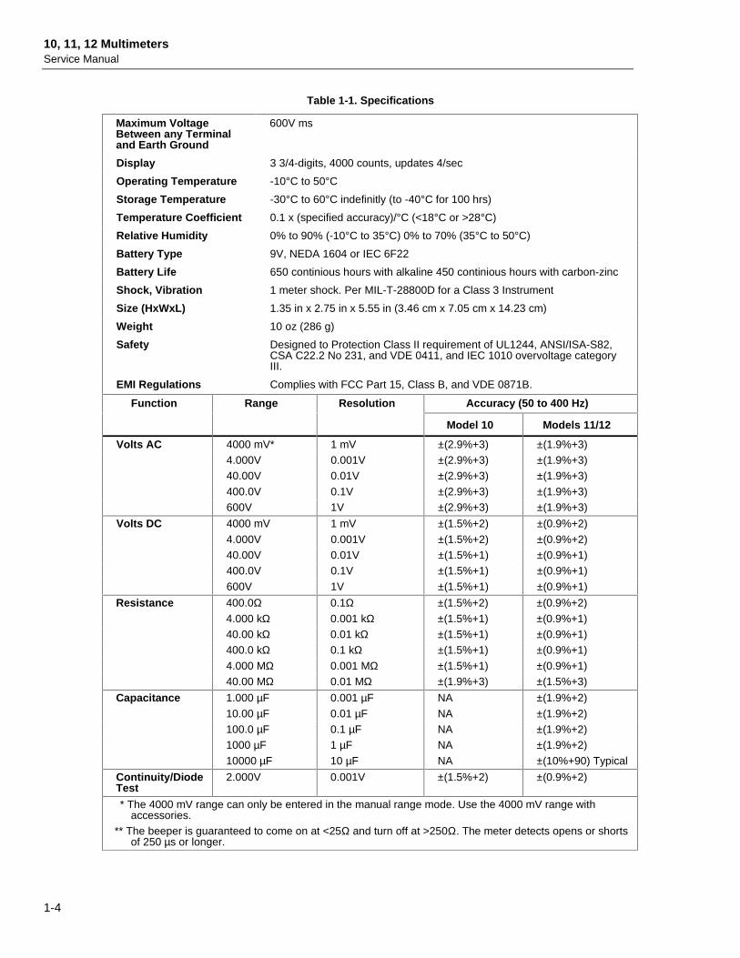
1-2. SpecificationsSpecifications are in Table 1-1. Accuracy is specified for a period of one year aftercalibration, at 18°C to 28°C (64°F to 82°F) with relative humidity to 90%. ACconversions are ac-coupled, average responding, and calibrated to the rms value of a sinewave input.
Accuracy specifications are given as:
±([% of reading] + number of least significant digits])
10, 11, 12 MultimetersService Manual
1-4
Table 1-1. Specifications
Maximum VoltageBetween any Terminaland Earth Ground
600V ms
Display 3 3/4-digits, 4000 counts, updates 4/sec
Operating Temperature -10°C to 50°C
Storage Temperature -30°C to 60°C indefinitly (to -40°C for 100 hrs)
Temperature Coefficient 0.1 x (specified accuracy)/°C (<18°C or >28°C)
Relative Humidity 0% to 90% (-10°C to 35°C) 0% to 70% (35°C to 50°C)
Battery Type 9V, NEDA 1604 or IEC 6F22
Battery Life 650 continious hours with alkaline 450 continious hours with carbon-zinc
Shock, Vibration 1 meter shock. Per MIL-T-28800D for a Class 3 Instrument
Size (HxWxL) 1.35 in x 2.75 in x 5.55 in (3.46 cm x 7.05 cm x 14.23 cm)
Weight 10 oz (286 g)
Safety Designed to Protection Class II requirement of UL1244, ANSI/ISA-S82,CSA C22.2 No 231, and VDE 0411, and IEC 1010 overvoltage categoryIII.
EMI Regulations Complies with FCC Part 15, Class B, and VDE 0871B.
Diode 600V rms 2, 4-3. 0V dc 2,400V dc 0.95 mA typical
* 3 x 10⁶ V Hz Maximum
** Models 11 and 12 only
MIN MAX Recording with Elapsed Time (Model 12 Only)
Specified accuracy of the measurement function ± 12 digits for changes >200 ms in duration (±40 digits inac). Typical 100 ms response to 80%.
Elapsed Time Resolution Accuracy
0 to 100 hours 1 minute 0.3% typical
(99:59)
Continuity Capture (Model 12 Only)
Detects opens or shorts of 250 µs or longer.
2-1
Chapter 2Theory of Operation
Title Page
2-1. Introduction........................................................................................... 2-32-2. Theory of Operation ............................................................................. 2-32-3. Analog Measurement IC (U1) .......................................................... 2-32-4. Microcomputer IC (U2).................................................................... 2-32-5. VCHEK Input Resistance................................................................. 2-3
10, 11, 12 MultimetersService Manual
2-2
Theory of OperationIntroduction 2
2-3
2-1. IntroductionSection 2 provides a basic theory of operation for the Series 10 Multimeters. Electricalcomponents on the printed circuit assembly (A1 Main PCA) are listed in Table 2-1.Refer to Figure 4-2 for the location of these components and Figures 4-3 through 4-5 forthe schematic diagrams.
2-2. Theory of OperationThe analog/digital IC (U1) implements the electrical measurement functions. See Table2-2 for pin names and descriptions. The microcomputer (U2) controls U1, the LCD (U3),and the user interface. Discrete components support U1 and U2, provide referencestandards for measurements, and provide input overload protection.
2-3. Analog Measurement IC (U1)U1 implements the following analog functions: a/d converter, ac to dc converter,VCHEK circuitry (Models 11 and 12 only), active filter, passive filter, power supply,range configuration circuitry, signal routing circuitry, beeper driver, digital controlcircuitry, and digital U2 interface circuitry.
The a/d converter is a patented dual-rate, dual-slope converter. The dual-rate conversionallows for MIN MAX (Model 12 only) and fast autoranging functions. The ac to dcconverter is full-wave rectified and average-responding. The active and passive filtersare two-pole and one-pole low-pass filters (respectively) that are used for signal filteringprior to a/d conversion. The internal power supply generates a ground voltage nominally+3V relative to VSS. Range configuration circuitry connects the Z1 resistor network asneeded for different ranges. Routing circuitry connects the various signal conditioningcircuits as needed. The a/d converter and a counter are controlled by a state machine.Finally, digital circuitry interfaces with U2 via a parallel address and bidirectional databus.
Voltage is measured using a ratio comparison of the unknown voltage to the referencevoltage (REFI pin). Resistance is calculated using a ratio comparison of the voltageacross the unknown resistor to the voltage across a precision reference resistor, with thesame current in both. Capacitance is measured by determining the amount of chargeadded for a given dc voltage change.
2-4. Microcomputer IC (U2)U2 writes range settings and a/d converter information to U1. U2 reads a/d converterresults and status information. This includes the low battery check, slide-switch position,continuity check, and VCHEK data. The microcomputer performs math operations onthe raw data from U1 and configures it for the LCD. U2 also reads pushbutton inputs.Finally, the 2.1 MHz clock signal at U2 is divided down to 131 kHz and sent to U1(CLK pin) for the counter.
2-5. VCHEK Input ResistanceAs shown in Figure 2-1, the input resistance for the VCHEK function is non-linear. Thedata in the graph are for the volts dc function (any range) and are the steady state valuesobtained after the PTC thermister (RT1) has stabilized. The data also apply for the voltsac function.
10, 11, 12 MultimetersService Manual
2-4
Table 2-1. Electrical Components on Main PCA
Circuit and Function Component Designator(s)
Analog Measurement IC U1
Microcomputer IC U2
Input Divider and Ohms Reference Resistor Network Z1
Input Divider AC Coupling Capacitor C14
J2 Input Receptable Voltage Sense Resistor R17
J1 Input Receptable Voltage Sense Resistor R14
Reference Voltage for Volts Measurements VR1, R4, R5, R6, R26
A/D Converter Integrate Capacitor C2
A/D Converter Autozero Capacitor C1
A/D Converter Gain Resistors R1, R3, R15
Active Filter Components R7, R8, C5, C6
Passive Filter Components R9, C7
AC to DC Converter Gain Resistors R11, R12, R13
AC to DC Converter AC Coupling Capacitor C8
Bias Current Setting Resistor R2
DGND-VSS Voltage Setting Resistors R10, R24
Power Supply Bypass Capacitors C3, C15
Reverse Battery Protection CR1
System Clock Y1
VCHEK Input Current Limiters R16, R18, R29
VCHEK input Positive Temp. Coef. Thermistor RT1
VCHEK Input Voltage Clamp Circuit Q1, Q2, CR2, R28
• Disassembly and reassembly• Cleaning• Performance tests• Calibration
3-2. Disassembly and ReassemblyWARNING
TO AVOID ELECTRICAL SHOCK, REMOVE TEST LEADS ANDANY INPUT SIGNALS BEFORE OPENING THE CASE.
CAUTIONTo avoid contamination from the fingers, handle the pca by theedges or wear gloves. PCA contamination can cause failures inhumid environments.
This meter contains components that can be damaged by staticdischarge. To avoid damaging these components whenservicing the meter, take precautions indicated on the "StaticAwareness" at the beginning of Section 3.
Referring to Figure 3-1 as necessary, disassemble the meter as follows. A Phillips-headscrewdriver and small flat-blade screwdriver are required.
1. Remove the test leads and set the slide-switch to OFF.
2. Remove the Phillips-head screws (H1-4) from the case bottom (MP8).
3. Separate the case top (MP2) from the case bottom.
4. TO REPLACE THE BATTERY: Lift the battery from the case bottom and insert anew 9V battery (NEDA 1604, 6F22, or 006P). Be sure the positive and negativebattery posts are oriented correctly.
5. TO REMOVE THE PCA (A1): Insert a small, flat-blade screwdriver between theedge of the case top and the pca where shown in Figure Gently unsnap a side of thecase top from the pca. Repeat on the other side of the pca. Unsnap the case from thetop of the pca last.
6. LIFT THE PCA FROM THE CASE TOP BY ITS EDGES. If the elastomeric contactstrips (J3, J4) for the switch assembly (S2) and LCD (U3) are stuck to the pca,remove them without touching the conductive edges.
TO REINSERT THE PCA: Important: First make sure that the slide-switch actuator(MP5) and slide-switch (S1) are both in the OFF position. Place the pca over thefour screw posts in the case top, then press gently on the center of the pca whileusing the small flat-edge screwdriver to shoehorn the pca under the snap on a sideof the case top. Repeat on the other side and the top.
7. TO REMOVE THE SWITCH SUPPORT (MP6): Hold the case top with the face ofmeter in your palm and press on the slide-switch actuator (MP5) to dislodge theswitch support. Lift out the switch support.
10, 11, 12 MultimetersService Manual
3-4
WINDOW DECAL (MP3)
CASE TOP (MP2)
ELASTOMERIC CONTACT STRIP, LCD (J3)
LCD (U3)
ELASTOMERIC CONTACT STRIP, SWITCH (MP9)
TOP SHIELD (MP7)
SWITCH SUPPORT (MP6)
MAIN PRINTED CIRCUIT ASSEMBLY (A1)
SHOCK ABSORBER (MP10)
9V BATTERY (BT1)
CASE BOTTOM (MP8)
4 PHILLIPS-HEAD SCREWS (H1-4)NON-SKID FOOT (MP11)
BOTTOM SHIELD (MP9)
SIDE-SWITCHACTUATOR (MP5)
SWITCH ASSEMBLY (S2)
CASE TOP DECAL (MP4)
ana02F.eps
Figure 3-1. Disassembled Unit
MaintenanceDisassembly and Reassembly 3
3-5
1
2
3
SNAP
SNAP
SNAPS
ana03f.eps
Figure 3-2. Removing and Reinserting the Printed Circuit Assembly
10, 11, 12 MultimetersService Manual
3-6
8. The LCD, switch assembly, slide-switch actuator, and elastomeric contact strips (J3, J4)for the LCD and switch assembly are accessible and can replaced as needed. Do notallow the LCD to get wet. Before installing a new LCD, make sure that all connectorcontact points are clean.
CAUTIONDo not touch the conductive edges of the elastomeric strips orthe contacts on the switch assembly. If they are contaminated,clean them with isopropyl alcohal.
9. Reassembling the meter is the reverse of disassembling it. After the meter isreassembled, execute the PERFORMANCE TESTS to confirm that the meter is workingproperly.
3-3. CleaningCAUTION
To avoid damaging the meter, do not use aromatic hydrocarbons orchlorinated solvents for cleaning. These solutions will react with theplastics used in the instruments. Do not get the LCD wet.
To clean the case, wipe it with a cloth lightly dampened with water and a mild detergent.
Wash the pca with isopropyl alcohol or hot deionized water and a soft brush. Do not usedetergent of any kind for cleaning the pca. The pca must be completely dry before themeter is reassembled. Dry the pca with clean dry air at low pressure (<20 psi), then bakeit at 50°C for 2 hours.
3-4. Performance TestsWARNING
TO AVOID SHOCK, DO NOT EXECUTE THE PERFORMANCETESTS PROCEDURES UNLESS THE METER IS FULLYASSEMBLED.
Use the PERFORMANCE TESTS to confirm that the meter is working properly. If themeter fails any of these tests, it needs calibration (see CALIBRATION) or repair. Theequipment required is specified in Table 3-1.
1. Connect the calibrator to the [+] and COM jacks on the meter.
2. Refering to Table 3-2 for the Fluke 10 or Table 3-3 for the Fluke 11 or 12, put themeter in the function and range shown for test 1.
MaintenanceCalibration 3
3-7
Table 3-1. Required Equipment
Equipment Minimum Specifications Recommended Model
3. Apply the input from the appropriate source. The reading on the display should bewithin the MINIMUM and MAXIMUM values shown in
4. Test the remaining functions and ranges.
3-5. CalibrationTo ensure that the meter performs to specifications, calibrate it annually using thefollowing procedure:
1. Set the calibrator for 0V dc. Put the meter in the 4.000V dc range.
2. Connect the calibrator to the [+] and COM jacks on the Meter.
3. Apply an input of +4.000V dc +/-0.25% The meter display should read between3.997-4.003V. If it does not, adjust R4 (see Figure 3-3) as follows.
To adjust R4:
1. Remove any input signals to the meter.
2. Remove the four screws on the back and separate the case bottom and case top.Notice that when you do so the battery remains in the case bottom and power to themeter is disconnected.
3. Observing correct polarity, connect a 9V battery to the battery contacts using easyhook jumpers or alligator clip leads (see Figure 3-3).
NOTETo avoid stretching or bending the battery contacts, connect leads to thebase of the contacts as shown in Figure 3-3.
4. Set the calibrator for 0V dc. Put the meter in the 4.000V dc range.
5. Connect the calibrator to the [+] and COM jacks on the Meter.
6. Apply an input of +4.000V dc +/-0.25%
7. Adjust R4 (see Figure 3-3) so that the meter display reads between 3.997-4.003V.
10, 11, 12 MultimetersService Manual
3-8
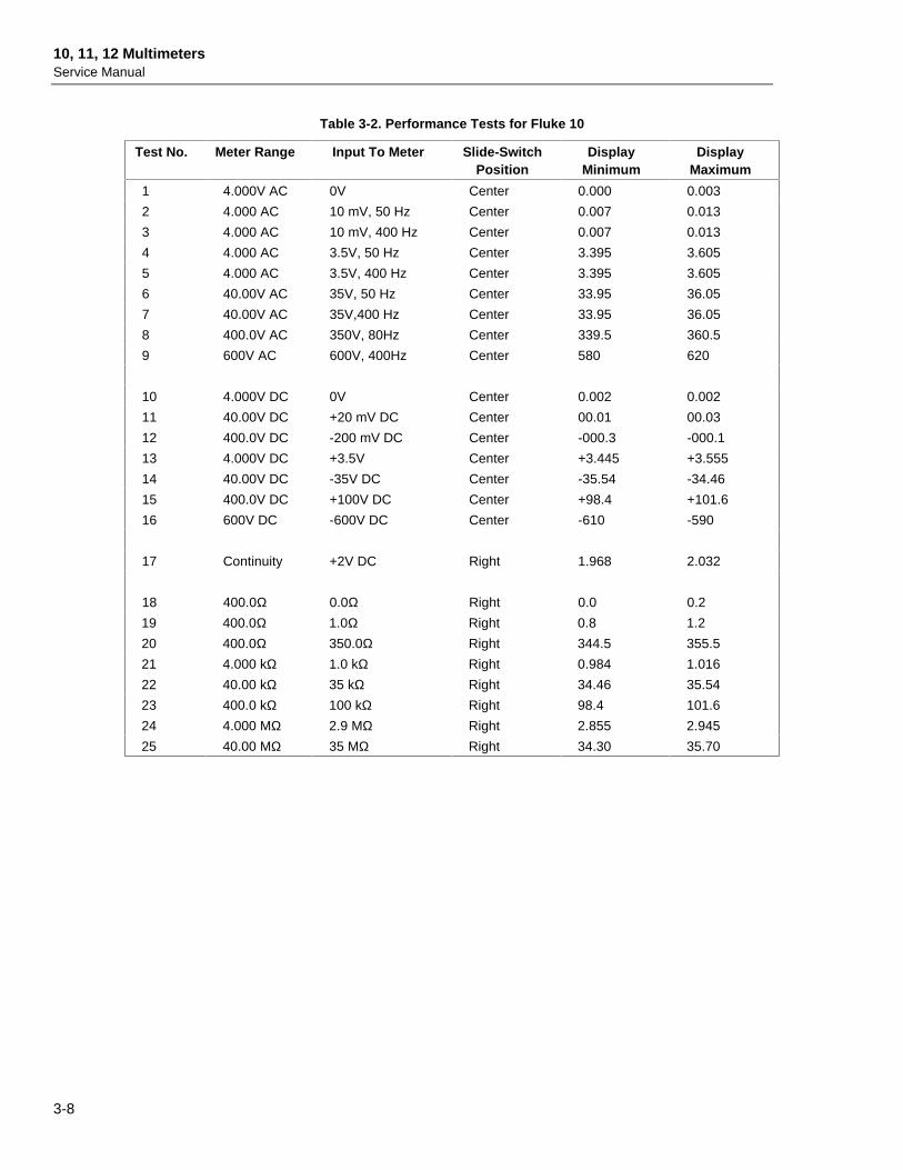
Table 3-2. Performance Tests for Fluke 10
Test No. Meter Range Input To Meter Slide-SwitchPosition
DisplayMinimum
DisplayMaximum
1 4.000V AC 0V Center 0.000 0.003
2 4.000 AC 10 mV, 50 Hz Center 0.007 0.013
3 4.000 AC 10 mV, 400 Hz Center 0.007 0.013
4 4.000 AC 3.5V, 50 Hz Center 3.395 3.605
5 4.000 AC 3.5V, 400 Hz Center 3.395 3.605
6 40.00V AC 35V, 50 Hz Center 33.95 36.05
7 40.00V AC 35V,400 Hz Center 33.95 36.05
8 400.0V AC 350V, 80Hz Center 339.5 360.5
9 600V AC 600V, 400Hz Center 580 620
10 4.000V DC 0V Center 0.002 0.002
11 40.00V DC +20 mV DC Center 00.01 00.03
12 400.0V DC -200 mV DC Center -000.3 -000.1
13 4.000V DC +3.5V Center +3.445 +3.555
14 40.00V DC -35V DC Center -35.54 -34.46
15 400.0V DC +100V DC Center +98.4 +101.6
16 600V DC -600V DC Center -610 -590
17 Continuity +2V DC Right 1.968 2.032
18 400.0Ω 0.0Ω Right 0.0 0.2
19 400.0Ω 1.0Ω Right 0.8 1.2
20 400.0Ω 350.0Ω Right 344.5 355.5
21 4.000 kΩ 1.0 kΩ Right 0.984 1.016
22 40.00 kΩ 35 kΩ Right 34.46 35.54
23 400.0 kΩ 100 kΩ Right 98.4 101.6
24 4.000 MΩ 2.9 MΩ Right 2.855 2.945
25 40.00 MΩ 35 MΩ Right 34.30 35.70
MaintenanceCalibration 3
3-9
Table 3-3. Performance Tests for Fluke 11 and 12
TestNo.
Meter Range Input ToMeter
Slide-SwitchPosition
DisplayMinimum
DisplayMaximum
1 4.000V AC 0V Center 0.000 0.003
2 4.000V AC,MIN MAX* 0V Center 0.000 0.040
3 4.000V AC 10 mV, 50 Hz Center 0.007 0.013
4 4.000V AC 10 mV, 400 Hz Right 0.007 0.013
5 4.000V AC 3.5V, 50 Hz Right 3.430 3.570
6 4.000V AC 3.5V, 400 Hz Center 3.430 3.570
7 40.00V AC 35V, 50 Hz Center 34.30 35.70
8 40.00V AC 35V, 400 Hz Right 34.30 35.70
9††† 400.0V AC 350V, 80 Hz Right 343.0 357.0
10 600V AC 600V, 400 Hz Center 586 614
11 4.000V DC,MIN MAX* 0V Center -0.012 0.012
12 4.000V DC 0V Right -0.002 0.002
13 40.00V DC +20 mV DC Right 00.01 00.03
14 400.0V DC -200mV DC Center -000.3 -000.1
15 4.000V DC +3.5V Center +3.466 +3.534
16 40.00V DC -35V DC Center -35.33 -34.67
17 400.0V DC +100V DC Center +99.0 +101.0
18 600V DC -600V DC Center -606 -594
19 Continuity +2V DC** Right 1.980 2.020
20 Continuity, VCHEK +3.43V DC** Right 3.397† 3.463†
21 Continuity, VCHEK -0.5V DC** Right -0.507† -0.493†
22 400.0Ω 0.0Ω Right 0.0 0.2
23 400.0Ω 1.0Ω Right 0.8 1.2
24 400.0Ω 350.0Ω Right 346.6 353.4
25 4.000 kΩ 1.0 kΩ Right 0.990 1.010
26 40.00 kΩ 35 kΩ Right 34.67 35.33
27 400.0 kΩ 100 kΩ Right 99.0 101.0
28 4.000 MΩ 2.9 MΩ Right 2.873 2.927
29 40.00 MΩ 35 MΩ Right 34.44 35.56
30 Ω, VCHEK 1.96V DC Right 1.940† 1.980†
31†† 1.000µF 0.0µF Right -0.001µF 0.001µF
32†† 1.000µF 0.95µF Right 0.93µF 0.970µF
* MIN MAX tests are for Fluke 12 only.** Calibrator 50Ω divider override.† The dc volts annunciator must be on.†† Conducting performance tests of the 400Ω, 4 kΩ, 40 kΩ, and 1 µF ranges (tests no. 22, 23, 24,25, 26, 31, and 32) verifies that the discrete and integrated circuitry needed to support the othercapacitance ranges are working within specifications. Therefore, these tests indirectly verify that themeter will meet specification in the 10 µF, 100 µF, 1000 µF, and 10,000 µF ranges.††† In the V-CHEK mode, the UUT uses a low-impedance thermistor (approx. 2.5 kΩ) for circuitprotection and load testing (referred to as lo-Z input circuitry). When using the 5100B or 5700A to drivethe UUT with higher voltages, avoid an overload/current limit condition by gradually stepping the voltageup (waiting two seconds between each step) from 90.0V, 120.0V, 180.0V and 350.0V at 80 Hz each step.
10, 11, 12 MultimetersService Manual
3-10
+ _9V
BATTERY
+
CLIP TO BASE OF CONTACTS
ADJUST R4 FOR 3.997-4.003V DC
INPUTRECEPTACLES
+
anao4f.eps
Figure 3-3. Calibration Adjustment
4-1
Chapter 4Replaceable Parts and Schematics
Title Page
4-1. Introduction........................................................................................... 4-34-2. How To Obtain Parts ............................................................................ 4-34-3. Schematics ............................................................................................ 4-34-4. Warranty and Service Centers .............................................................. 4-4
10, 11, 12 MultimetersService Manual
4-2
Replaceable Parts and SchematicsIntroduction 4
4-3
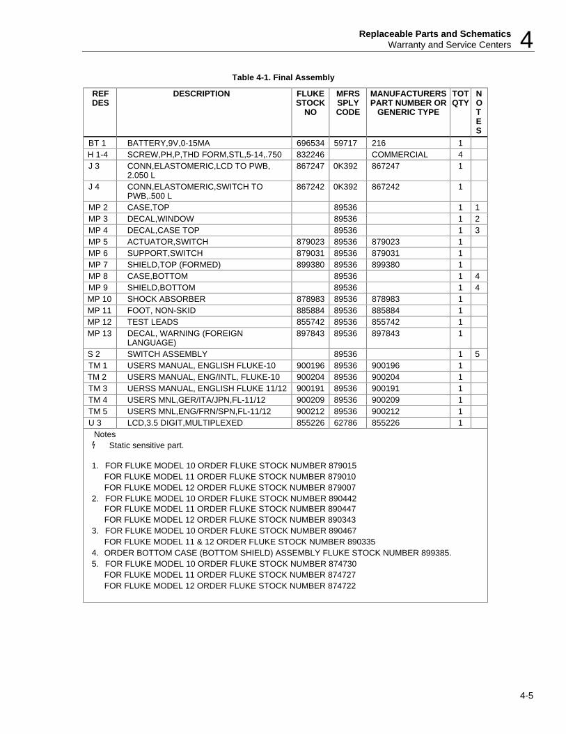
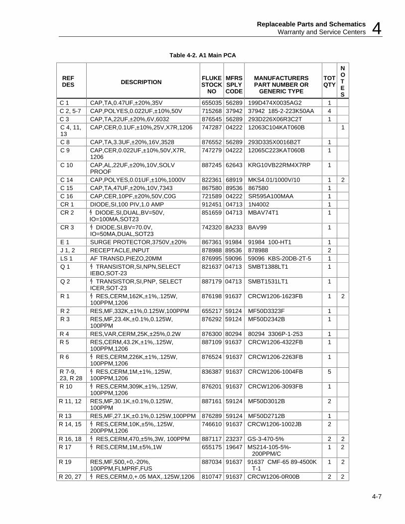
4-1. IntroductionThis section contains an illustrated list of replaceable parts and a schematic drawing forSeries 10 Multimeters. Parts are listed by assembly; alphabetized by referencedesignator. Parts unique to a specific model are identified. Each assembly isaccompanied by an illustration showing the location of each part and its referencedesignator. The parts lists give the following information:
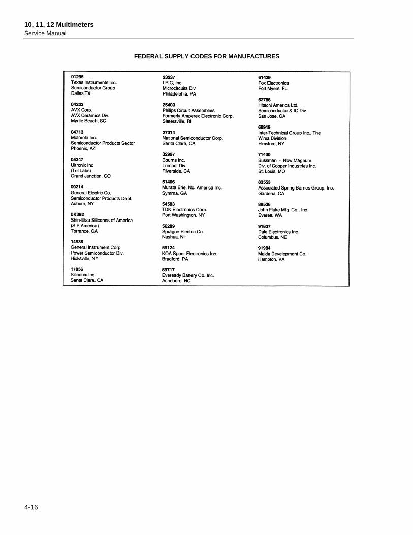
• Reference designator• An indication if the part is subject to damage by static discharge• Description• Fluke stock number• Manufacturers supply code for manufacturers. (code-to-name list at end• of this section)• Manufacturers’ part number or generic type• Total quantity• Any special notes (i.e., factory-selected part)• Manufacturers part number or generic type• Total quantity• Any special notes (i.e., factory-selected part)
CAUTIONA symbol indicates a device that may be damaged by staticdischarge.
4-2. How To Obtain PartsElectrical components may be ordered directly from the manufacturer by using themanufacturers part number, or from the John Fluke Mfg. co., Inc. and its authorizedrepresentatives by using the part number under the heading FLUKE STOCK NO. In theU.S. order directly from the Fluke Parts Dept. by calling 1-800-526-4731. Parts priceinformation is available from the John Fluke Mfg. Co., Inc or its representatives. Pricesare also available in a Fluke Replacement Parts Catalog which is available on request.
In the event that the part ordered has been replaced by a now or improved part, thereplacement will be accompanied by an explanatory note and installation instructions, ifnecessary.
To ensure prompt delivery of the correct part, include the following information whenyou place an order:
• Instrument model and serial number• Description (as given under the DESCRIPTION heading)• Quantity• Reference designator• Part number and revision level of the pca containing the part.• Fluke stock number
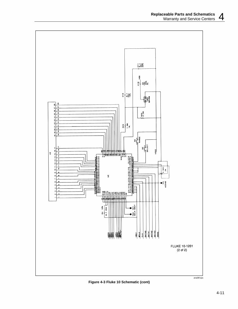
4-3. SchematicsFigures 4-3 through 4-5 are schematics of the Series 10 Multimeters.
10, 11, 12 MultimetersService Manual
4-4
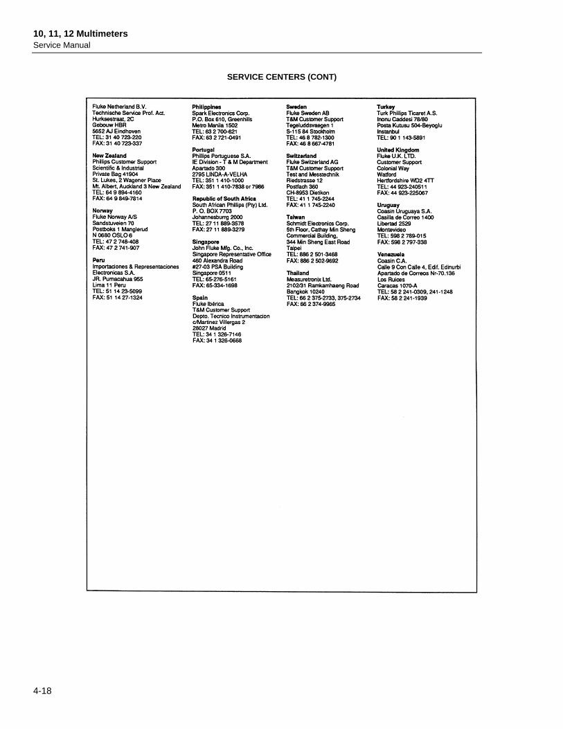
4-4. Warranty and Service CentersThe Series 10 Multimeters are warranted for two years. The warranty is printed behindthe title page of this manual. For service information, in the USA call 1-800-825-9810.Outside the USA, contact a Fluke service center. A list of service centers is at the end ofSection 4.
NOTE This instrument may contain a Nickel-Cadmium battery. Do not mix withthe solid waste stream. Spent batteries should be disposed of by a qualifiedrecycler or hazardous materials handler. Contact your authorized Flukeservice center for recycling information.
WARNINGTHIS INSTRUMENT CONTAINS A FUSIBLE RESISTOR (PN887034). TO ENSURE SAFETY, USE EXACT REPLACEMENTONLY.
Replaceable Parts and SchematicsWarranty and Service Centers 4
1. FOR FLUKE MODEL 10 ORDER FLUKE STOCK NUMBER 879015FOR FLUKE MODEL 11 ORDER FLUKE STOCK NUMBER 879010FOR FLUKE MODEL 12 ORDER FLUKE STOCK NUMBER 879007
2. FOR FLUKE MODEL 10 ORDER FLUKE STOCK NUMBER 890442FOR FLUKE MODEL 11 ORDER FLUKE STOCK NUMBER 890447FOR FLUKE MODEL 12 ORDER FLUKE STOCK NUMBER 890343
3. FOR FLUKE MODEL 10 ORDER FLUKE STOCK NUMBER 890467FOR FLUKE MODEL 11 & 12 ORDER FLUKE STOCK NUMBER 890335
4. ORDER BOTTOM CASE (BOTTOM SHIELD) ASSEMBLY FLUKE STOCK NUMBER 899385.5. FOR FLUKE MODEL 10 ORDER FLUKE STOCK NUMBER 874730
FOR FLUKE MODEL 11 ORDER FLUKE STOCK NUMBER 874727FOR FLUKE MODEL 12 ORDER FLUKE STOCK NUMBER 874722
10, 11, 12 MultimetersService Manual
4-6
MP3
MP2
J3
U3
J4
MP7
MP6
A1
MP10
BT1
MP8
H1-4MP11
MP7
MP9
MP5
S2
MP4
ana05f.eps
Figure 4-1. Final Assembly Drawing
Replaceable Parts and SchematicsWarranty and Service Centers 4