17
Flyin’ Miata ECU installation instructions for 1.6L Miatas Revision .5 2-3-05
| Date post: | 15-Mar-2018 |
| Category: |
Documents |
| Upload: | duongduong |
| View: | 245 times |
| Download: | 4 times |
�
Flyin’ Miata ECU installationinstructions for 1.6L Miatas
Revision �.5�2-�3-05
2
ContentsSection �: Introduction ..........................................................................3Section 2: Mounting the FM ECU ........................................................4Section 3: Wiring Changes ...................................................................5 Ground Wire Modification ....................................................6 Sequential Fuel Injection (optional) ......................................7 Wide Band O2 Sensor (optional) .........................................7 Fan Control (optional) ..........................................................8Section 4: Air Temperature Sensor .......................................................9 Turbocharged Cars ..............................................................9 Supercharged Cars ...........................................................�0 Normally Aspirated Cars .................................................... ��Section 5: Fuel Injectors ....................................................................�2Section 6: MAP Sensor ......................................................................�4Section 7: Knock Sensor ....................................................................�5Section 8: Boost Control Solenoid ......................................................�7
3
Section 1: Introduction
The FM ECU completely replaces the factory ECU to take full control of the engine’s func-tions. The ECU fits into the factory ECU case and plugs into the factory ECU harness. Since the ECU was first designed, we have added 5 new features that require moving and/or adding wires in the factory wire harness. These modifications are outlined in section 3 of the following instructions.
For the wire splicing called for in this manual we recommend, and include, heat shrinkable crimp connectors. A crimp connection is better both structurally and electrically than a solder connection. If you do not believe us, try to find a soldered connection in your Miata wiring. The integrity of a crimp connection depends on the quality of the tools used for the installation. Go to Sears and invest in a high quality pair of wire crimping pliers. These can be bought for $25 to $30 and will quickly pay for themselves in this and future projects.
The included crimp connectors use a heat shrinkable coating. Once the wires are crimped in place, heat the connector with a heat gun (buy one of these at Sears with your crimping tool) to shrink down the outer covering. This will provide a water tight seal for the life of your car.
4
Section 2: Mounting the FM ECU
The factory ECU is found under the carpet in the passenger side footwell.
�) Disconnect one of the terminals on the battery.
2) Remove the plastic trim on the passenger side door sill. Pull back the carpeting and remove the four nuts and one bolt holding the steel plate covering the ECU.
3) Remove the wire harness by pressing down on the tab in the center of the connectors and pulling down on the plugs. The ECU can now be removed from the car.
4) Take the ECU to a workbench where it can be worked on. Remove the phillips screws that hold the mounting brackets and the top and bottom covers on the ECU case. Remove the two small screws holding the heat sink to the side of the ECU case.
5) Remove the phillips head screws that are holding the printed circuit board and remove the stock board. Install the FM ECU board in place of the stock board and reinstall the screws. The small heat sink screws will not be reused.
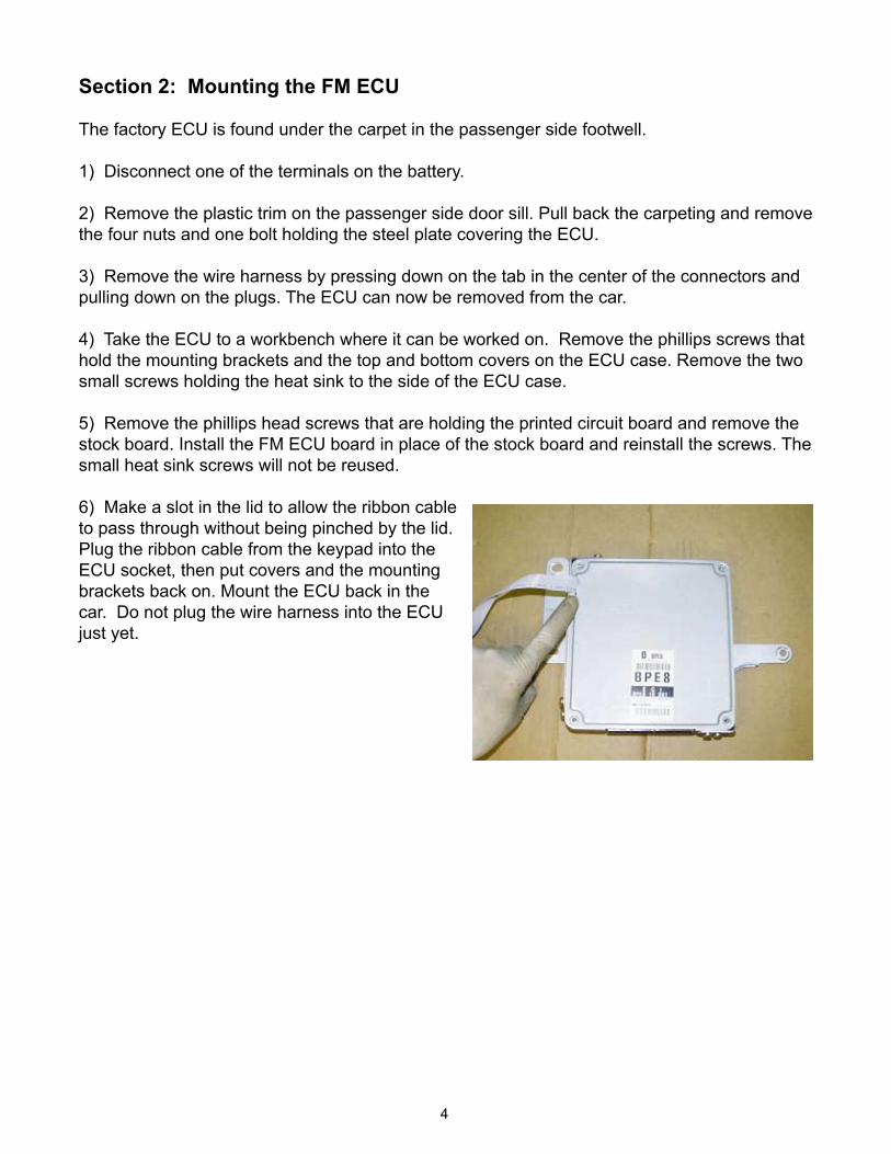
6) Make a slot in the lid to allow the ribbon cable to pass through without being pinched by the lid. Plug the ribbon cable from the keypad into the ECU socket, then put covers and the mounting brackets back on. Mount the ECU back in the car. Do not plug the wire harness into the ECU just yet.
5
Section 3: Wiring Changes
Since the FM ECU’s initial design we have added knock sensing, turbo boost control, intake air temperature measurement, sequential fuel injection, cooling fan control and a modified ground wire path to the ECU’s operation. To utilize these new features three wires have to be moved in the ECU plugs and four wires must be added to the ECU plugs. If any of these features are not going to be used, the corresponding wire does not have to be moved or added. Moving or adding a wire and not using the function will not affect operation of the ECU.
Note: The intake air temperature sensor is not optional, it must be used in order for the FM ECU to work properly.
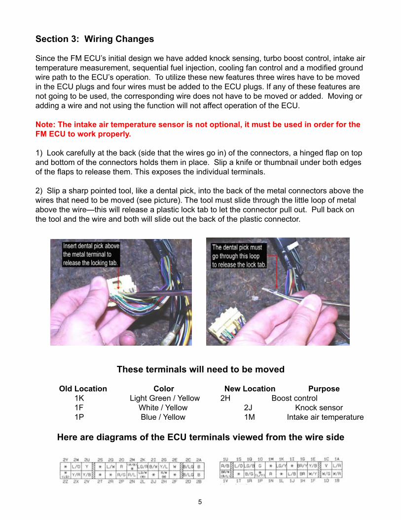
1) Look carefully at the back (side that the wires go in) of the connectors, a hinged flap on top and bottom of the connectors holds them in place. Slip a knife or thumbnail under both edges of the flaps to release them. This exposes the individual terminals.
2) Slip a sharp pointed tool, like a dental pick, into the back of the metal connectors above the wires that need to be moved (see picture). The tool must slide through the little loop of metal above the wire—this will release a plastic lock tab to let the connector pull out. Pull back on the tool and the wire and both will slide out the back of the plastic connector.
These terminals will need to be moved
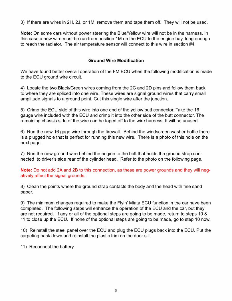
Old Location Color New Location Purpose 1K Light Green / Yellow 2H Boost control 1F White / Yellow 2J Knock sensor 1P Blue / Yellow 1M Intake air temperature
Here are diagrams of the ECU terminals viewed from the wire side
6
3) If there are wires in 2H, 2J, or 1M, remove them and tape them off. They will not be used.
Note: On some cars without power steering the Blue/Yellow wire will not be in the harness. In this case a new wire must be run from position 1M on the ECU to the engine bay, long enough to reach the radiator. The air temperature sensor will connect to this wire in section #4.
Ground Wire Modification
We have found better overall operation of the FM ECU when the following modification is made to the ECU ground wire circuit.
4) Locate the two Black/Green wires coming from the 2C and 2D pins and follow them back to where they are spliced into one wire. These wires are signal ground wires that carry small amplitude signals to a ground point. Cut this single wire after the junction.
5) Crimp the ECU side of this wire into one end of the yellow butt connector. Take the �6 gauge wire included with the ECU and crimp it into the other side of the butt connector. The remaining chassis side of the wire can be taped off to the wire harness. It will be unused.
6) Run the new 16 gage wire through the firewall. Behind the windscreen washer bottle there is a plugged hole that is perfect for running this new wire. There is a photo of this hole on the next page.
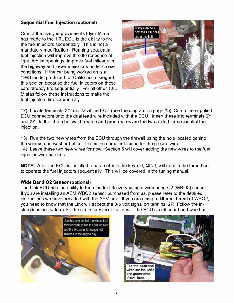
7) Run the new ground wire behind the engine to the bolt that holds the ground strap con-nected to driver’s side rear of the cylinder head. Refer to the photo on the following page.
Note: Do not add 2A and 2B to this connection, as these are power grounds and they will neg-atively affect the signal grounds.
8) Clean the points where the ground strap contacts the body and the head with fine sand paper.
9) The minimum changes required to make the Flyin’ Miata ECU function in the car have been completed. The following steps will enhance the operation of the ECU and the car, but they are not required. If any or all of the optional steps are going to be made, return to steps 10 & 11 to close up the ECU. If none of the optional steps are going to be made, go to step 10 now.
�0) Reinstall the steel panel over the ECU and plug the ECU plugs back into the ECU. Put the carpeting back down and reinstall the plastic trim on the door sill.
��) Reconnect the battery.
7
Sequential Fuel Injection (optional)
One of the many improvements Flyin’ Miata has made to the 1.6L ECU is the ability to fire the fuel injectors sequentially. This is not a mandatory modification. Running sequential fuel injection will improve throttle response at light throttle openings, improve fuel mileage on the highway and lower emissions under cruise conditions. If the car being worked on is a 1993 model produced for California, disregard this section because the fuel injectors on these cars already fire sequentially. For all other 1.6L Miatas follow these instructions to make the fuel injectors fire sequentially.
12) Locate terminals 2Y and 2Z at the ECU (use the diagram on page #5). Crimp the supplied ECU connectors onto the dual lead wire included with the ECU. Insert these into terminals 2Y and 2Z. In the photo below, the white and green wires are the two added for sequential fuel injection.
13) Run the two new wires from the ECU through the firewall using the hole located behind the windscreen washer bottle. This is the same hole used for the ground wire.�4) Leave these two new wires for now. Section 5 will cover adding the new wires to the fuel injection wire harness.
NOTE: After the ECU is installed a parameter in the keypad, QINJ, will need to be turned on to operate the fuel injectors sequentially. This will be covered in the tuning manual.
Wide Band O2 Sensor (optional)The Link ECU has the ability to tune the fuel delivery using a wide band O2 (WBO2) sensor. If you are installing an AEM WBO2 sensor purchased from us, please refer to the detailed instructions we have provided with the AEM unit. If you are using a different brand of WBO2, you need to know that the Link will accept the 0-5 volt signal on terminal 2P. Follow the in-structions below to make the necessary modifications to the ECU circuit board and wire har-
8
ness to accept the WBO2 signal in terminal 2P. Making the appropriate ECU settings will be covered in the ECU tuning manual. Use the diagrams on page 5 to locate the wire positions.
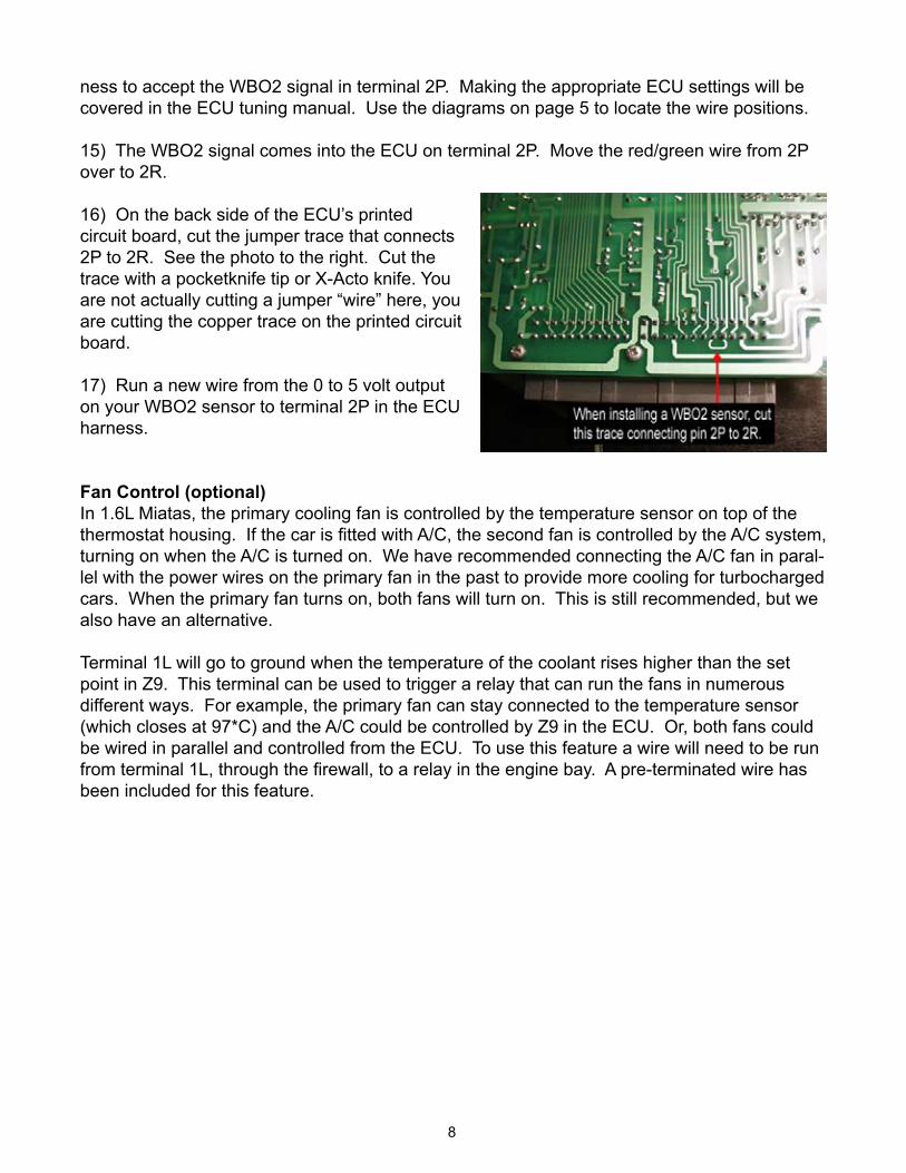
15) The WBO2 signal comes into the ECU on terminal 2P. Move the red/green wire from 2P over to 2R.
�6) On the back side of the ECU’s printed circuit board, cut the jumper trace that connects 2P to 2R. See the photo to the right. Cut the trace with a pocketknife tip or X-Acto knife. You are not actually cutting a jumper “wire” here, you are cutting the copper trace on the printed circuit board.
�7) Run a new wire from the 0 to 5 volt output on your WBO2 sensor to terminal 2P in the ECU harness.
Fan Control (optional)In 1.6L Miatas, the primary cooling fan is controlled by the temperature sensor on top of the thermostat housing. If the car is fitted with A/C, the second fan is controlled by the A/C system, turning on when the A/C is turned on. We have recommended connecting the A/C fan in paral-lel with the power wires on the primary fan in the past to provide more cooling for turbocharged cars. When the primary fan turns on, both fans will turn on. This is still recommended, but we also have an alternative.
Terminal �L will go to ground when the temperature of the coolant rises higher than the set point in Z9. This terminal can be used to trigger a relay that can run the fans in numerous different ways. For example, the primary fan can stay connected to the temperature sensor (which closes at 97*C) and the A/C could be controlled by Z9 in the ECU. Or, both fans could be wired in parallel and controlled from the ECU. To use this feature a wire will need to be run from terminal 1L, through the firewall, to a relay in the engine bay. A pre-terminated wire has been included for this feature.
9
Section 4: Air Temperature Sensor
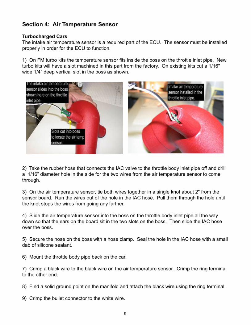
Turbocharged CarsThe intake air temperature sensor is a required part of the ECU. The sensor must be installed properly in order for the ECU to function.
1) On FM turbo kits the temperature sensor fits inside the boss on the throttle inlet pipe. New turbo kits will have a slot machined in this part from the factory. On existing kits cut a 1/16" wide 1/4" deep vertical slot in the boss as shown.
2) Take the rubber hose that connects the IAC valve to the throttle body inlet pipe off and drill a 1/16” diameter hole in the side for the two wires from the air temperature sensor to come through.
3) On the air temperature sensor, tie both wires together in a single knot about 2" from the sensor board. Run the wires out of the hole in the IAC hose. Pull them through the hole until the knot stops the wires from going any farther.
4) Slide the air temperature sensor into the boss on the throttle body inlet pipe all the way down so that the ears on the board sit in the two slots on the boss. Then slide the IAC hose over the boss.
5) Secure the hose on the boss with a hose clamp. Seal the hole in the IAC hose with a small dab of silicone sealant.
6) Mount the throttle body pipe back on the car.
7) Crimp a black wire to the black wire on the air temperature sensor. Crimp the ring terminal to the other end.
8) FInd a solid ground point on the manifold and attach the black wire using the ring terminal.
9) Crimp the bullet connector to the white wire.
�0
10) On top of the power steering pump is a Blue/Yellow wire. This is the same wire moved at the ECU plug. Pull this wire off the power steering pump by pulling it straight up. Connect the white wire from the air temperature sensor to the female bullet connector on this wire.
11) If the car is not fitted with power steering, but the Blue/Yellow wire was moved at the ECU harness, the Blue/Yellow wire will be tied off to the breather line behind the thermostat housing. Connect the white wire from the air temperature sensor to the female bullet connector on this wire.
12) If the Blue/Yellow wire was not in the wire harness down at the ECU, then the new wire run out to the engine bay on page 6 will now be connected to the white wire on the air temper-ature sensor. Contact FM if you need an ECU pin to connect the wire to the harness.
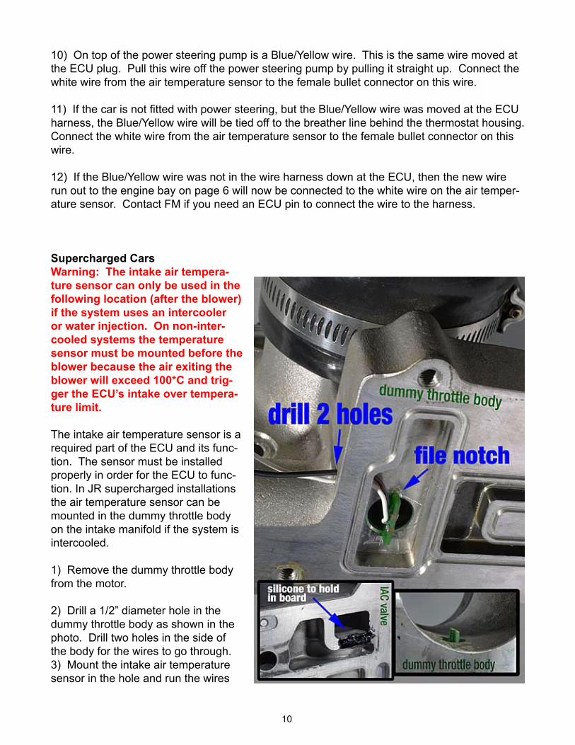
Supercharged CarsWarning: The intake air tempera-ture sensor can only be used in the following location (after the blower) if the system uses an intercooler or water injection. On non-inter-cooled systems the temperature sensor must be mounted before the blower because the air exiting the blower will exceed 100*C and trig-ger the ECU’s intake over tempera-ture limit.
The intake air temperature sensor is a required part of the ECU and its func-tion. The sensor must be installed properly in order for the ECU to func-tion. In JR supercharged installations the air temperature sensor can be mounted in the dummy throttle body on the intake manifold if the system is intercooled.
�) Remove the dummy throttle body from the motor.
2) Drill a 1/2” diameter hole in the dummy throttle body as shown in the photo. Drill two holes in the side of the body for the wires to go through. 3) Mount the intake air temperature sensor in the hole and run the wires
��
out the two small holes. Secure the sensor in place with a small dab of silicone sealant.
4) Mount the dummy throttle body pipe back on the car.
5) Crimp the black 48” wire to the black wire on the air temperature sensor. Crimp the ring terminal to the other end.
6) Run the black wire along the intake manifold to the firewall. Wire tie it to the steel brake booster pipe and run it over to the driver’s side of the engine. Crimp on the ring terminal and connect the wire to the ground point on the rear of the head used for the ECU.
7) Crimp the bullet connector to the white wire.
8) On the top of the power steering pump is a Blue/Yellow wire. This is the same wire moved at the ECU plug. Pull this wire off the power steering pump by pulling it straight up. Connect the white wire from the air temperature sensor to the female bullet connector on this wire.
9) If the car is not fitted with power steering, but the Blue/Yellow wire was moved at the ECU harness, the Blue/Yellow wire will be tied off to the breather line behind the thermostat housing. Connect the white wire from the air temperature sensor to the female bullet connector on this wire.
9) If the Blue/Yellow wire was not in the wire harness at the ECU, then the new wire run out to the engine bay will now be connected to the white wire on the air temperature sensor.
Normally Aspirated Cars
Since the intake system on normally aspirated cars can vary greatly and there is no compres-sion of the intake charge, the intake air temperature sensor can be mounted almost any where. For example, if an open element air filter is used, the sensor can be secured to the outer sur-face of the filter with a zip tie. On systems using the factory plastic crossover pipe, the sensor can be mounted somewhere in the pipe. Just make sure the sensor does not move or vibrate. It must be held securely in place.
Follow the wiring instructions for either the supercharger or turbocharger section.
�2
Section 5: Fuel Injectors
This section covers replacing the stock fuel injectors with the larger units required for boosted operation, as supplied in the FMII kit. This ECU has high impedance injector drivers (11-16 ohm). Previous FMII systems came with SL440cc injectors, and they are supported with the defaults up to the 26-Apr-2005 chip. Future kits will come with SL550cc injectors, and will be supported with a chip revision to the defaults after that date. We supply enough spade con-nectors with the injectors that you can keep the stock clips with the stock injectors and easily swap back as necessary. On normally aspirated installations the stock injectors will be used, but follow the steps below for completing the sequential injection.
Note: 93 California cars came sequential from the factory, and this mod is not required.
�) Remove the gas cap to relieve pressure in the fuel tank.
2) Remove the four 6mm bolts holding the air valve on the side of the intake plenum and re-move the air valve. Coolant will not leak out when removing this piece.
3) Unplug the electrical connectors for the fuel injectors. Unplug the fuel injection harness from the main harness at the rear of the intake manifold. Unplug the two water temperature sensors on the rear of the head. The fuel injection harness can now be removed from the motor.
4) Remove the tape around the wire harness on all four of the fuel injectors. Cut off the stock fuel injector connectors about 2” back from the connector itself.
5) Take the four new fuel injector connectors supplied with the fuel injectors and cut the wires down to 2” in length.
6) On positions #1 & #2 splice the new connectors on the harness just as the stock connectors were configured using the red butt connectors.
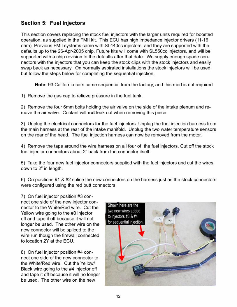
7) On fuel injector position #3 con-nect one side of the new injector con-nector to the White/Red wire. Cut the Yellow wire going to the #3 injector off and tape it off because it will not longer be used. The other wire on the new connector will be spliced to the wire run though the firewall connected to location 2Y at the ECU.
8) On fuel injector position #4 con-nect one side of the new connector to the White/Red wire. Cut the Yellow/Black wire going to the #4 injector off and tape it off because it will no longer be used. The other wire on the new
�3
connector will be spliced to the wire run through the firewall connected to location 2Z at the ECU.
9) Tape up the modified harness.
�0) Remove the two 8mm bolts holding the fuel rail in place. There are two black plastic spac-ers between the fuel rail and the head that will be loose when the bolts are removed, don’t lose them!
NOTE: Some fuel will spray out at this point so have a disposable towel ready and do NOT have a droplight nearby.
11) Once the bolts are out, wiggle the fuel rail off the injectors and pull the injectors out, being very careful not to lose the little black rings on the lower ends of the injectors. These rings will be re-used.
�2) Prepare the new injectors by transferring the lower rings from the old injectors to the new injectors. Use a small amount of grease to make the rings slide on easier. Lubricate the o-rings at the top of the injector and the inside of the rail where they go with grease as well, be-ing careful not to get any grease into the injectors.
�3) Fit the new injectors into the holes in the cylinder head with the electrical connectors up. Slide the fuel rail down over the rubber o-rings. The o-rings fit tightly into the fuel rail, so push the fuel rail down firmly. The grease should keep the o-rings from pinching.
�4) Install the spacers and 8mm bolts to secure the fuel rail to the head.
�5) Reinstall the wire harness and the air valve.
�4
Section 6: MAP Sensor
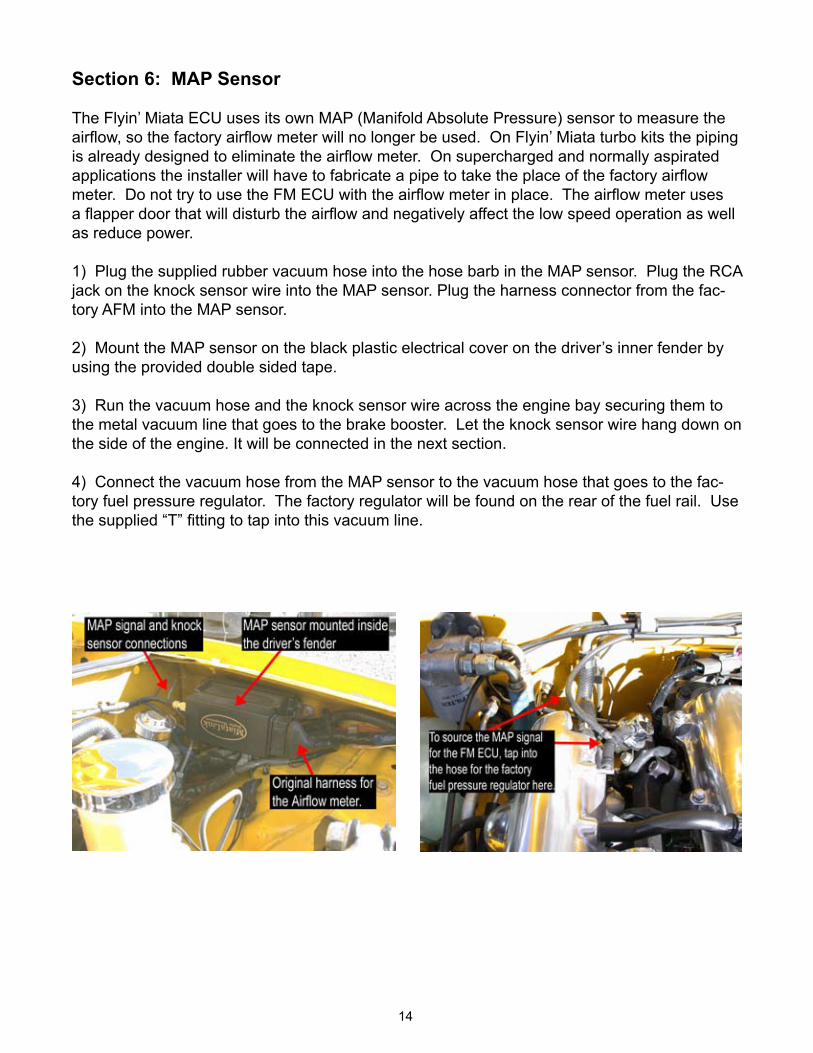
The Flyin’ Miata ECU uses its own MAP (Manifold Absolute Pressure) sensor to measure the airflow, so the factory airflow meter will no longer be used. On Flyin’ Miata turbo kits the piping is already designed to eliminate the airflow meter. On supercharged and normally aspirated applications the installer will have to fabricate a pipe to take the place of the factory airflow meter. Do not try to use the FM ECU with the airflow meter in place. The airflow meter uses a flapper door that will disturb the airflow and negatively affect the low speed operation as well as reduce power.
�) Plug the supplied rubber vacuum hose into the hose barb in the MAP sensor. Plug the RCA jack on the knock sensor wire into the MAP sensor. Plug the harness connector from the fac-tory AFM into the MAP sensor.
2) Mount the MAP sensor on the black plastic electrical cover on the driver’s inner fender by using the provided double sided tape.
3) Run the vacuum hose and the knock sensor wire across the engine bay securing them to the metal vacuum line that goes to the brake booster. Let the knock sensor wire hang down on the side of the engine. It will be connected in the next section.
4) Connect the vacuum hose from the MAP sensor to the vacuum hose that goes to the fac-tory fuel pressure regulator. The factory regulator will be found on the rear of the fuel rail. Use the supplied “T” fitting to tap into this vacuum line.
�5
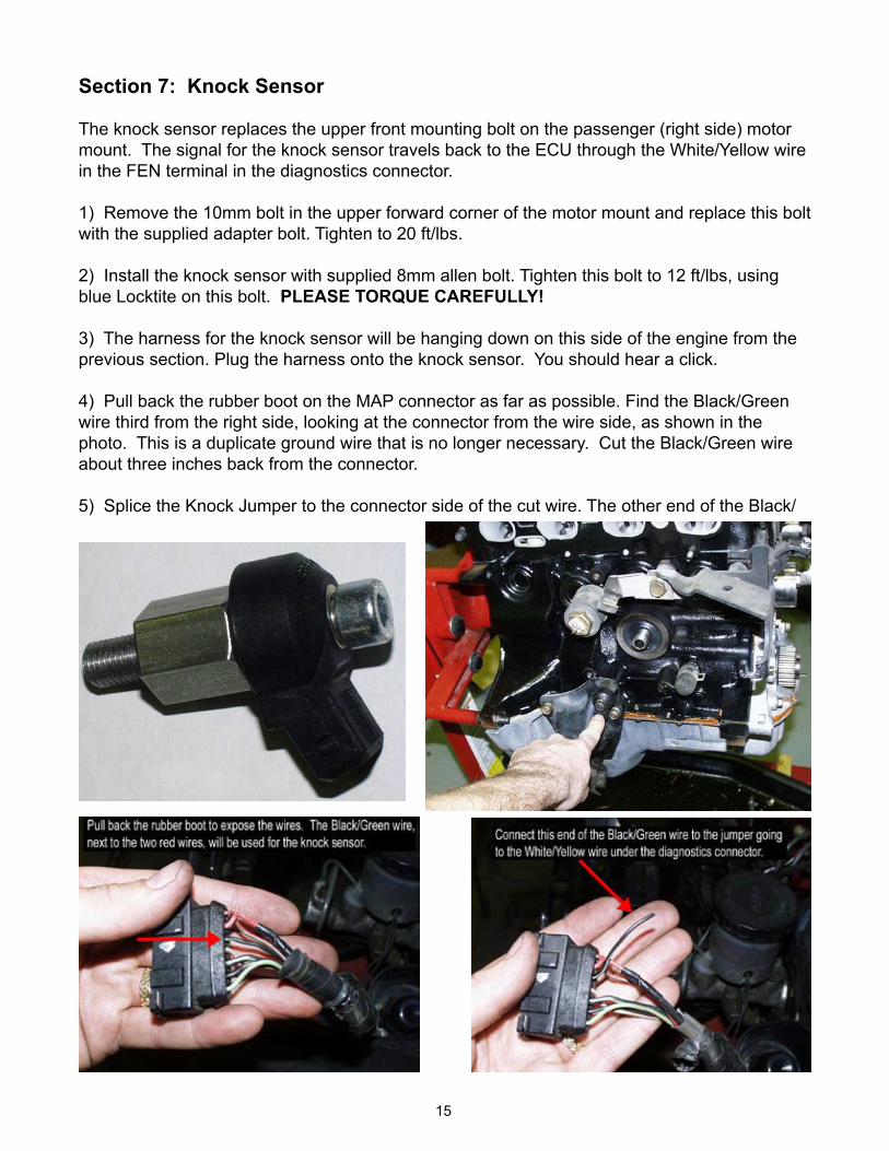
Section 7: Knock Sensor
The knock sensor replaces the upper front mounting bolt on the passenger (right side) motor mount. The signal for the knock sensor travels back to the ECU through the White/Yellow wire in the FEN terminal in the diagnostics connector.
�) Remove the �0mm bolt in the upper forward corner of the motor mount and replace this bolt with the supplied adapter bolt. Tighten to 20 ft/lbs.
2) Install the knock sensor with supplied 8mm allen bolt. Tighten this bolt to 12 ft/lbs, using blue Locktite on this bolt. PLEASE TORQUE CAREFULLY!
3) The harness for the knock sensor will be hanging down on this side of the engine from the previous section. Plug the harness onto the knock sensor. You should hear a click.
4) Pull back the rubber boot on the MAP connector as far as possible. Find the Black/Green wire third from the right side, looking at the connector from the wire side, as shown in the photo. This is a duplicate ground wire that is no longer necessary. Cut the Black/Green wire about three inches back from the connector.
5) Splice the Knock Jumper to the connector side of the cut wire. The other end of the Black/
�6
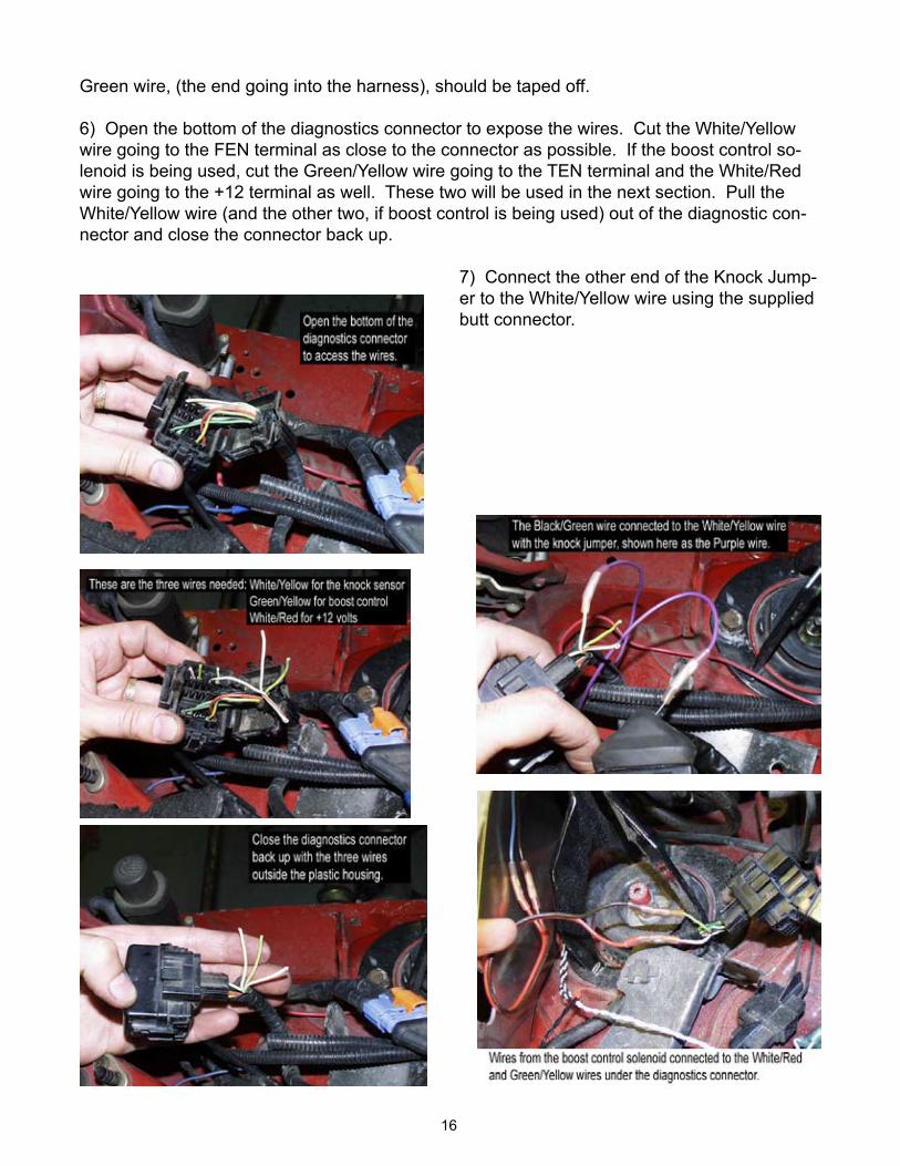
Green wire, (the end going into the harness), should be taped off.
6) Open the bottom of the diagnostics connector to expose the wires. Cut the White/Yellow wire going to the FEN terminal as close to the connector as possible. If the boost control so-lenoid is being used, cut the Green/Yellow wire going to the TEN terminal and the White/Red wire going to the +12 terminal as well. These two will be used in the next section. Pull the White/Yellow wire (and the other two, if boost control is being used) out of the diagnostic con-nector and close the connector back up.
7) Connect the other end of the Knock Jump-er to the White/Yellow wire using the supplied butt connector.
�7
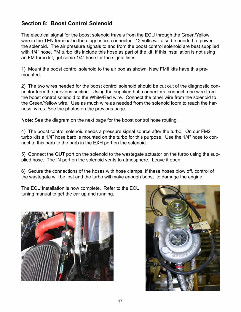
Section 8: Boost Control Solenoid
The electrical signal for the boost solenoid travels from the ECU through the Green/Yellow wire in the TEN terminal in the diagnostics connector. �2 volts will also be needed to power the solenoid. The air pressure signals to and from the boost control solenoid are best supplied with 1/4” hose. FM turbo kits include this hose as part of the kit. If this installation is not using an FM turbo kit, get some 1/4” hose for the signal lines. 1) Mount the boost control solenoid to the air box as shown. New FMII kits have this pre-mounted.
2) The two wires needed for the boost control solenoid should be cut out of the diagnostic con-nector from the previous section. Using the supplied butt connectors, connect one wire from the boost control solenoid to the White/Red wire. Connect the other wire from the solenoid to the Green/Yellow wire. Use as much wire as needed from the solenoid loom to reach the har-ness wires. See the photos on the previous page.
Note: See the diagram on the next page for the boost control hose routing.
4) The boost control solenoid needs a pressure signal source after the turbo. On our FM2 turbo kits a 1/4” hose barb is mounted on the turbo for this purpose. Use the 1/4" hose to con-nect to this barb to the barb in the EXH port on the solenoid.
5) Connect the OUT port on the solenoid to the wastegate actuator on the turbo using the sup-plied hose. The IN port on the solenoid vents to atmosphere. Leave it open.
6) Secure the connections of the hoses with hose clamps. If these hoses blow off, control of the wastegate will be lost and the turbo will make enough boost to damage the engine.
The ECU installation is now complete. Refer to the ECU tuning manual to get the car up and running.


