CHAPTER 7 120-mm MORTAR, M120 The 120-mm mortar delivers timely, accurate fires to meet the requirements of supported troops. This chapter discusses assigned personnel duties, organization, mounting the mortar, and characteristics . Section I. SQUAD AND SECTION ORGANIZATION AND DUTIES Each member of the infantry mortar squad has principle duties and responsibilities. 7-1. ORGANIZATION For the mortar section to operate effectively, each squad member must be proficient in his individual duties. By performing those duties as a team member, he enables the mortar squad and section to perform as a fighting team. The platoon leader commands the platoon and supervises the training of the elements. He uses the chain of command to assist him in effecting his command and supervising duties. 7-2. DUTIES The mortar squad consists of five men (Figure 7-1). Their firing positions and principal duties are as follows:
Transcript
CHAPTER 7
120-mm MORTAR, M120
The 120-mm mortar delivers timely, accurate fires to meet the requirements of supported troops. This chapter discusses assigned personnel duties, organization, mounting the mortar, and characteristics.
Section I. SQUAD AND SECTION ORGANIZATION AND DUTIES
Each member of the infantry mortar squad has principle duties and responsibilities.
7-1. ORGANIZATION
For the mortar section to operate effectively, each squad member must be proficient in his individual duties. By performing those duties as a team member, he enables the mortar squad and section to perform as a fighting team. The platoon leader commands the platoon and supervises the training of the elements. He uses the chain of command to assist him in effecting his command and supervising duties.
7-2. DUTIES
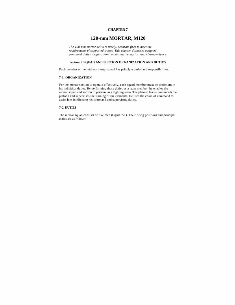
The mortar squad consists of five men (Figure 7-1). Their firing positions and principal duties are as follows:
Figure 7-1. Position of squad members.
a. The squad leader stands behind the mortar where he can command and control his squad. In addition to supervising the emplacement, laying, and firing of the mortar, he supervises all other squad activities.
b. The gunner stands to the left side of the mortar where he can manipulate the sight, elevating handwheel, and traversing handwheel. He places firing data on the sight and lays the mortar for deflection and elevation. He makes large deflection shifts by shifting the bipod assembly and keeps the bubbles level during firing.
c. The assistant gunner stands to the right of the mortar, facing the barrel and ready to load. In addition to loading, he swabs the bore after 10 rounds have been fired or after each fire mission. He assists the gunner in shifting the mortar when the gunner is making large deflection changes.
d. The first ammunition bearer stands to the right rear of the mortar. He has the duty of preparing the ammunition and passing it to the assistant gunner. He is also the squad driver.
e. The second ammunition bearer stands to the right rear of the mortar behind the ammunition bearer. He maintains the ammunition for firing and provides local
security for the mortar position. He performs other duties as the squad leader directs. He is also the driver for the ammunition vehicle.
Section II. COMPONENTS
This section contains the technical data and description of each component of the 120-mm mortar (Figure 7-2). The mortar is a smooth-bore, muzzle-loaded, crew-served, high angle-of-fire weapon. It consists of a cannon assembly, bipod assembly, and baseplate. The 120-mm mortar is designed to be employed in all phases and types of land warfare, and in all weather conditions. (See TM 9-1015-250-10 for detailed information.)
Figure 7-2. The 120-mm mortar.
7-3. TABULATED DATA FOR THE 120-mm MORTAR, M120
The tabulated data for the 120-mm mortar are as shown in Table 7-1.
Elevation (approximate mils) Elevation For each turn of elevation crank
0710 to 1510
5
Traverse (approximate mils) Right or left from center using traversing wheel With extension One turn of traversing wheel
136
316
5
Range (meters) Maximum Minimum
7,200 200
Rate of Fire (rounds per minute) Maximum Sustained
16 (first minute) 4 (indefinitely)
Bursting Radius (meters) 75
Table 7-1. Tabulated data for the 120-mm, M120 mortar.
7-4. BARREL ASSEMBLY, M298
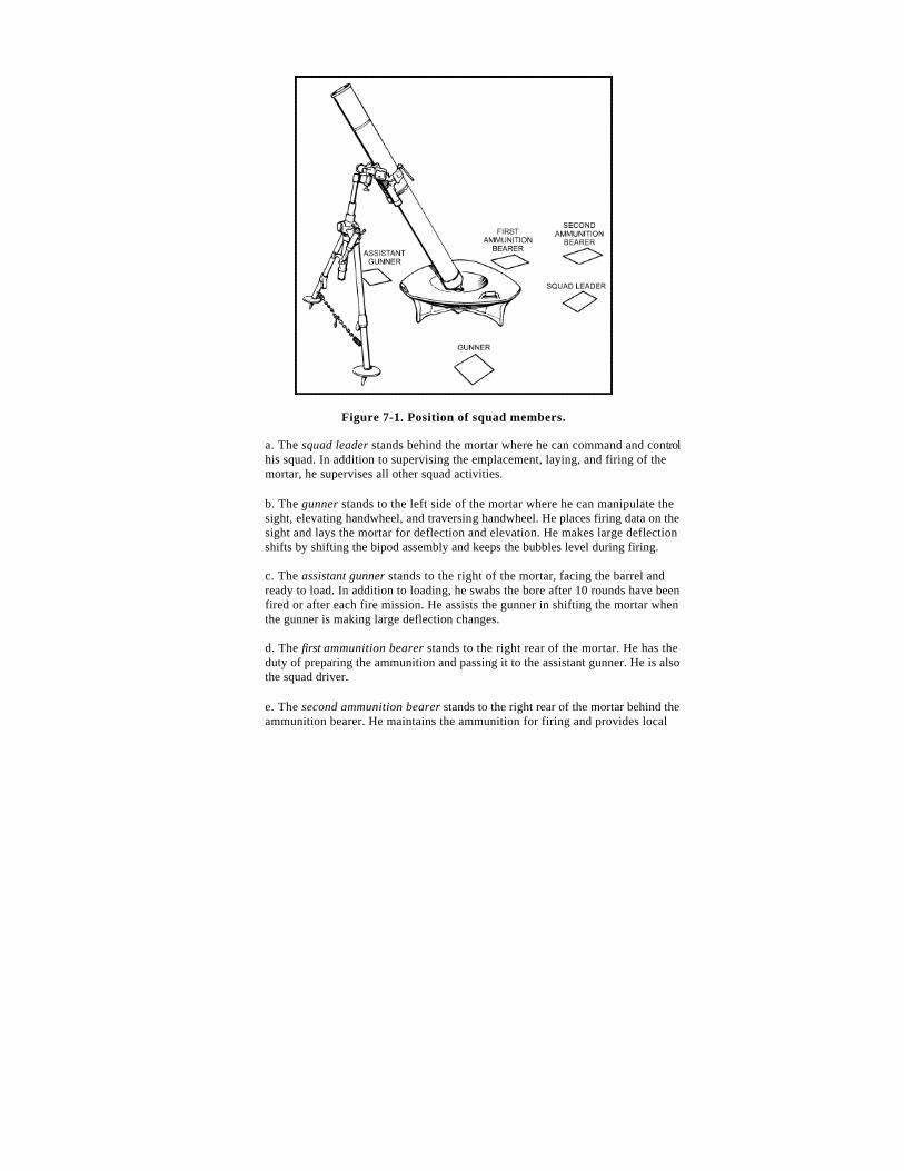
The barrel assembly consists of two parts: the tube and the base cap (Figure 7-3). The rear end of the tube is threaded to form a seat, which functions as a gas seal and centers the base cap.
Figure 7-3. Barrel assembly, M298.
a. The base cap screws into the base end of the tube with the front end of the base cap mating to the seat on the tube, forming a gas-tight metal seal. The external rear portion of the base cap is tapered and has a ball-shaped end. This end is cross-bored to help inserting or removing the base cap and locking it into firing position. The safety lever has two positions: F for fire and S for safe.
b. When the safety lever shows the letter F, the firing pin protrudes and is in the fire position. When the lever shows the letter S, the weapon is in the safe position and the firing pin is withdrawn.
Note : The barrel and cap are serial numbered identically. They should not be interchanged.
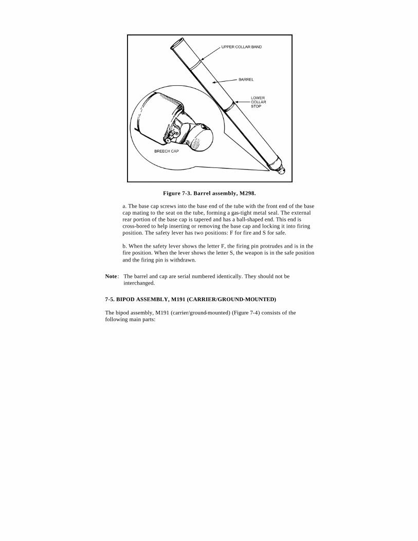
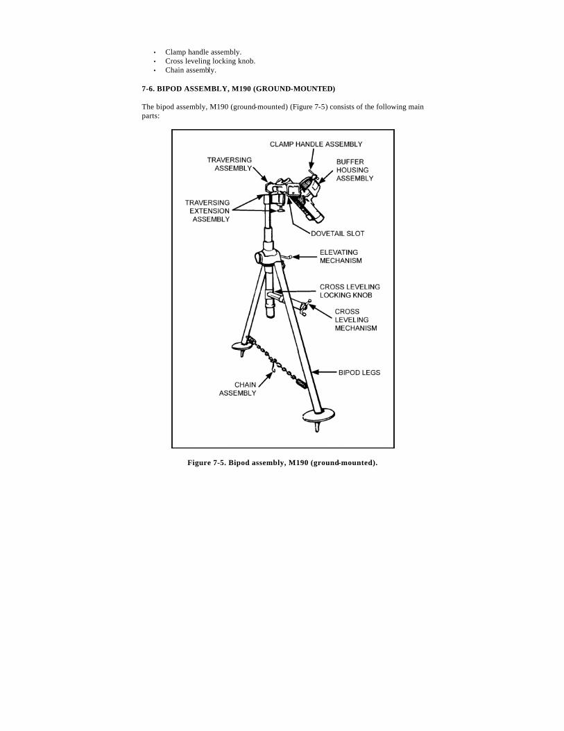
The baseplate (Figure 7-6) is shaped like a rounded triangle. It has a socket that enables a full 360-degree traverse without moving the baseplate. It also has legs (spades) under the baseplate, two carrying handles, and one locking handle.
Figure 7-6. Baseplate, M9.
Section III. OPERATIONS
This section explains how to place the mortar into action by ground-mounting and leveling the weapon system from the trailer position; how to conduct safety checks; and what actions the crew applies to remove the cartridge from the barrel if a misfire should occur during firing.
7-8. PLACING A GROUND-MOUNTED 120-mm MORTAR INTO ACTION
The assistant gunner and two ammunition bearers are present. The mortar must be ground-mounted within 1 minute and 15 seconds. The M67 sight is set with a deflection of 3200 mils and an elevation of 1100 mils. All bubbles are centered within the outer red
lines. The traversing extension is locked in the center position. The bearing is the center of traverse. The barrel is locked into the baseplate with the white line up (on top). The bipod barrel clamp is positioned and locked. The bipod locking knob is hand tight.
Note : Left and right are in relation to the mortar’s direction of fire.
a. The driver/first ammunition bearer exits the mortar carrier and moves to the driver’s side of the mortar trailer hitch. At the same time, the second ammunition bearer exits the armament vehicle and moves to the passenger’s side of the mortar trailer hitch.
b. Together, they unhook the trailer from the vehicle and position the trailer at the firing position with the baseplate toward the direction of fire. The first ammunition bearer then removes the muzzle plug.
c. The assistant gunner exits the vehicle with the aiming posts and places them to the right side of the mortar.
d. Once in position, both ammunition bearers raise the trailer until the baseplate is resting on the ground. The second ammunition bearer then releases the trailer while the first ammunition bearer continues to hold the trailer in place. The second ammunition bearer moves around to the right side of the mortar to assist in mounting the mortar.
e. The gunner exits the vehicle with the sight and places it on the left side of the mortar. He then moves up to the left side of the mortar and removes the lock release lever pin. He releases the mortar baseplate and unhooks the bipod chain from the eye on the bipod leg and drops it. He then loosens the cross-level locking knob.
WARNING
Stay clear of the mortar baseplate to avoid injury from sudden release.
f. The assistant gunner assumes his position on the right side of the mortar. He releases the lock release lever and then the clamping catch, and swings the trailer bridge assembly out of the way. He raises the bipod legs and rotates them 180 degrees. He spreads the bipod legs until they are fully extended, and the spread chain is taut. Once the bipod is placed on the ground, the assistant gunner tightens the cross-level locking knob.
g. With the gunner standing on the left and the second ammunition bearer on the right, they grasp the traversing mechanism and bipod legs. With the assistant
gunner holding the bipod legs just above the spread chain, they pull and guide the barrel forward away from the trailer. The assistant gunner guides the bipod legs to a point (about 2 feet) in front of the baseplate and lowers them to the ground. At this point, the mortar is free from the trailer.
h. The first ammunition bearer moves the trailer to the point selected by the squad leader away from the mortar position.
i. The gunner unlocks the clamp handle assembly. The gunner, who is now standing to the rear and straddling the barrel, grasps under the recoil buffer assembly and pulls down, sliding the barrel clamp down the barrel until it rests against the lower collar stop.
j. The gunner makes sure the white lines on the barrel and the buffer housing assembly are aligned. He retightens the clamp handle assembly until it "clicks." Then, he places the selector switch on FIRE (F). The assistant gunner checks for slack in the spreader chain and ensures the traversing mechanism is within four turns from center of traverse. The assistant gunner also ensures the traversing extension is locked in the center position and the cross-leveling locking knob is hand tight.
Note : Part of the white line on the buffer housing assembly must overlap the white line on the barrel.
k. The gunner removes the sight from the sight box and indexes a deflection of 3200 mils and an elevation of 1100 mils on the sight. He places the sight in the dovetail slot of the bipod. The gunner and assistant gunner then level the mortar for elevation and deflection. When the gunner is satisfied with the lay of the mortar, he announces, "Gun up." The mortar is now mounted and ready to be reciprocally laid.
7-9. PERFORMING SAFETY CHECKS ON A GROUND-MOUNTED 120-mm MORTAR
Specific safety checks must be performed before firing mortars. Most can be made visually. The gunner is responsible for physically performing the checks under the squad leader’s supervision.
a. The gunner checks for mask and overhead clearance.
(1) To determine mask clearance, the gunner lowers the barrel to 0800 mils elevation. He places his head near the base of the barrel and sights along the top of the barrel for obstructions through the full range of traverse.
(2) To determine overhead clearance, the gunner raises the barrel to 1500 mils elevation. He places his head near the base of the barrel and sights along the top of the barrel for obstructions through the full range of traverse.
Note : If at any point in the full range of traverse, both at minimum or maximum elevation, an obstruction is found, the gunner raises or lowers the barrel until the round will clear the obstruction when fired. He turns the sight elevation micrometer knob until the elevation bubble is level. He reads the elevation at this point and reports the deflection and elevation to the squad leader who, in turn, reports this information to the FDC.
b. The gunner ensures the barrel is locked to the baseplate.
(1) He locks the barrel onto the socket of the baseplate with the white line on the barrel facing up.
(2) He aligns the white line on the barrel with the white line on the clamp handle assembly.
c. The gunner checks the buffer housing assembly to ensure that it is locked. He checks this by loosening the clamp handle assembly about 1/4 of a turn and retightening it until a metallic click is heard.
d. The gunner checks the cross-leveling locking knob to ensure it is hand tight.
e. The gunner checks the spreader chain to ensure that it is taut.
f. The gunner checks the firing selector to ensure it is in the FIRE position with the "F" showing.
7-10. PERFORMING SMALL DEFLECTION AND ELEVATION CHANGES ON A GROUND-MOUNTED 120-mm MORTAR
The gunner receives deflection and elevation changes from the FDC in the form of a fire command. If a deflection change is required, it precedes the elevation change.
Note : Small deflection and elevation changes are greater than 20 mils but less than 60 mils for deflection and greater than 35 mils but less than 90 mils for elevation.
a. The gunner sets the sight for deflection and elevation.
(1) He places the deflection on the sight by turning the deflection micrometer knob until the correct 100-mil deflection mark is indexed on the coarse deflection scale. He continues to turn the deflection micrometer
knob until the remainder of the deflection is indexed on the deflection micrometer scale.
(2) The gunner places the elevation on the sight by turning the elevation micrometer knob until the correct 100-mil elevation mark is indexed on the coarse elevation scale. He continues to turn the elevation micrometer knob until the remainder of the elevation is indexed on the micrometer scale.
b. The gunner lays the mortar for deflection.
(1) After the deflection and elevation are indexed on the sight, the gunner floats the elevation bubble.
(2) He turns the elevating hand crank to elevate or depress the mortar until the bubble in the elevation level vial starts to move. This initially rough lays the mortar for elevation.
(3) After rough laying the mortar for elevation, the gunner looks through the sight and traverses to realign on the aiming post. He traverses half the distance to the aiming post, then cross-levels.
(4) Once the vertical cross line is near the aiming posts (about 20 mils), the gunner checks the elevation vial. If required, he re-lays for elevation by elevating or depressing the elevating mechanism. He makes final adjustments using the traversing handwheel and cross-levels by traversing half the distance and cross-leveling.
(5) When the vertical cross line is within 2 mils of the aiming posts, all bubbles are leveled, and the sight is set on a given deflection, the mortar is laid.
Note : If the given deflection exceeds left or right traverse, the gunner may choose to use the traversing extension assembly. This gives him an added number of mils in additional traverse to avoid moving the bipod. To use the traversing extension, the gunner pulls down on the traversing extension locking knob and shifts the cannon left or right. He re-locks the traversing extension locking knob by ensuring it is securely seated.
7-11. PERFORMING LARGE DEFLECTION AND ELEVATION CHANGES ON A GROUND-MOUNTED 120-mm MORTAR
The gunner receives deflection and elevation changes from the FDC in the form of a fire command. If a deflection change is required, it will always precede the elevation change. The gunner lays the mortar for a large deflection and elevation change.
Note : Large deflection and elevation changes are greater than 200 mils but less than 300 mils for deflection and greater than 100 mils but less than 200 mils for elevation.
a. The gunner receives a deflection and elevation change in the form of an initial fire command.
Note : All elements of the fire command are repeated by the gun squad.
b. As soon as the gunner receives the data, he places it on the sight and elevates or depresses the mortar to float the elevation bubble.
c. The assistant gunner positions himself in front of the bipod. He squats slightly with his legs spread shoulder-width apart and supports his elbows on his knees. He grabs the bipod legs and lifts them until the bipod clears the ground.
d. The gunner moves the mortar by placing his right hand over the clamp handle assembly and his left hand on the bipod leg. He pushes or pulls the bipod in the direction desired until the vertical cross line is within 20 mils of the aiming posts. Once completed, the gunner directs the assistant gunner to lower the bipod. He then floats the deflection bubble and looks into the sight to see if he is within 20 mils of his aiming posts.
e. The gunner and assistant gunner level the mortar for elevation. If after leveling the mortar for elevation, the vertical cross line of the M67 sight is within 20 mils of the aiming post, he would then center the deflection bubble and take up the proper sight picture by traversing half the distance to the aiming posts and cross-leveling.
f. The assistant gunner observes the gunner traversing to ensure that he stays within four turns of center-of-traverse. Should the gunner traverse away from center-of-traverse, the assistant gunner advises and instructs the gunner to center back up. The gunner center traverses, and with the help of the assistant gunner, he shifts the bipod again and repeats steps c through e .
Note : After leveling the mortar, if the vertical cross line of the M67 sight is not within 20 mils of the aiming post, then steps c through e are repeated.
g. The gunner makes minor adjustments as necessary and does a final check of the bubbles and center-of-traverse, and announces, "Up."
7-12. MALFUNCTIONS ON A GROUND-MOUNTED 120-mm MORTAR
See Chapter 3, paragraph 3-14 for a detailed discussion of malfunctions.
7-13. PERFORMING MISFIRE PROCEDURES ON A GROUND-MOUNTED 120-mm MORTAR DURING COMBAT
The barrel assembly of the towed 120-mm mortar must be at its lowest elevation to perform the misfire procedures. When a misfire occurs, all crew members, or the crew member that first notices, shout, "MISFIRE."
WARNING
To avoid possible injury to the crew, do not stand in front of or behind the barrel.
a. At the announcement of a misfire, all crew members remain with the mortar.
Note : During peacetime live-fire exercises, all crew members except the gunner will leave the firing position and move at least 100 meters to the rear of the mortar position.
b. The gunner stands to the left rear of the mortar and kicks the barrel several times. If the round does not fire, the gunner waits for one minute. (This allows the round to fire if there is a delayed action [hang fire] of the propelling charge.) After the one-minute wait, the gunner performs the following:
(1) He checks the barrel for heat using his bare hands. Starting at the muzzle, he lightly touches the barrel with his fingertips every few inches down to the breech cap. If the barrel is too hot, the crew uses some means (such as water or snow) to cool it down before attempting to removing the misfire.
(2) If the barrel is cool enough to handle, the gunner places the weapon on SAFE with the "S" showing.
c. The gunner locks the data down on the sight unit, removes the sight and places it in a safe place (sight box), and calls the crew forward.
d. The gunner then depresses the barrel to its lowest elevation using the elevation handwheel, leaving about a quarter inch of sleeve showing (so there is no metal to metal contact).
CAUTION
At no time will the clamp handle assembly be loosened (except during jammed or stuck rounds.
e. The assistant gunner secures the staff assembly with the extractor attached. He rotates it forward, stabilizing the extractor, and inserts the extractor into the cannon. He lowers it slowly into the cannon (hand over hand) until the extractor makes contact with the round. He rotates the extractor in either direction until he feels the detent pins connect into the round. He continues rotating until resistance is felt.
f. The assistant gunner lifts up slightly on the extractor to ensure it has connected with the round. He continues lifting the extractor until the body of the round appears at the muzzle. At this time, the gunner grasps the round and assists in removing the round. Together they move to the right of side of the weapon.
Note : Due to the weight of the round, the gunner may assist during the entire extraction process.
CAUTION
Once the assistant gunner ensures the extractor is firmly connected with the round, he extracts the round in one steady motion (using the hand-over-hand process) without stopping or lowering the round.
Note : If the round is jammed or stuck and cannot be removed by the extractor, the gunner holds the barrel and unlocks the clamp handle assembly while the assistant gunner stabilizes the bipod. The first ammunition bearer grasps the base of the cannon and rotates the it until the white line is in the down position while the gunner lifts the cannon to release it from the baseplate. The assistant gunner moves the bipod to the right and out of the way. The gunner and first ammunition bearer lift the cannon to a horizontal position and carry it, with the extractor in place, to the dud pit. Ensuring the cannon remains pointed down range, the platoon leader or platoon sergeant notifies EOD personnel.
g. The gunner stands to the left side of the weapon in the gunner’s position. He holds his hands ready near the muzzle to grasp the round as soon as the body of the round clears the muzzle. The assistant gunner and gunner then complete removing the round from the barrel. Once the round has cleared the barrel, both crew members move to the right of the mortar position. The ammunition bearer comes forward and stands beside the gunner.
h. With the assistant gunner holding the round extractor by the handle and the gunner holding the round, the ammunition bearer presses on all four catches on the extractor at the same time, releasing the round from the extractor.
i. The gunner inspects the round. If the primer has been struck by the firing pin, the round is disposed of in accordance with range SOP. If no contact was made
with the firing pin, action is taken to clean any possible obstructions inside the barrel.
Note : Nondevelopment item (NDI) ammunition will not be refired.
j. The assistant gunner swabs the bore and the gunner places the safety mechanism on "F" (FIRE).
k. The gunner re-installs the sight, re-lays the mortar, and continues the mission.
Note : If the extractor cannot grasp the round, use another extractor if possible. If the extractor still cannot grasp the round, follow steps l through q.
l. The gunner holds the cannon near the muzzle and the assistant gunner holds the bipod assembly. The gunner opens the buffer housing assembly.
m. The gunner ad ammunition bearer turn the cannon until the white line is in the down position and carefully remove the cannon from the breech cap socket.
n. Keeping the cannon horizontal and pointing in the direction of fire, the gunner and ammunition bearer move the cannon to the opposite side of the ammunition point. The assistant gunner places the ends of his thumbs over the edges of the muzzle, grasping the cannon with his fingers.
o. At the assistant gunner’s command of LIFT, the ammunition bearer lifts the cannon’s breech cap assembly causing the round to slide down to the assistant gunner’s hands. The assistant gunner removes the round, inspects it, tries to replace the safety wire (if applicable), places the round in the dud pit, tags the round, and notifies EOD.
p. The assistant gunner swabs the bore.
q. The gunner re-lays the mortar and continues the mission.
Note : If the round is grasped but cannot be removed, follow steps r through t.
r. The gunner holds the cannon near the muzzle, and the assistant gunner holds the bipod assembly. The gunner opens the buffer housing assembly.
s. The gunner and ammunition bearer turn the cannon until the white line is n the down position and carefully remove the cannon from the breech cap socket.
t. Keeping the cannon horizontal and pointing in the direction of fire, the gunner and ammunition bearer lift the cannon (with the extractor still attached to the
round) and carry it to the dud pit, ensuring it remains pointing downrange. The platoon leader or platoon sergeant notifies EOD.
7-14. LOADING AND FIRING THE GROUND-MOUNTED 120-mm MORTAR
The following paragraphs explain the procedures for loading and firing a ground-mounted 120-mm mortar.
a. The FDC issues a fire command to the squad leader.
b. The squad leader records and issues the fire command to the squad.
c. The squad repeats the fire commands.
d. The ammunition bearer(s) prepares the round(s) IAW the fire command.
e. The ammunition bearer prepares the round so that the squad leader can inspect it before it is passed to the assistant gunner. The ammunition bearer holds the round with both hands (palms up) near each end of the round body (not on the fuze or the charges).
f. The assistant gunner checks the round for correct charges, fuze tightness, and fuze setting.
g. When both the gun and the round(s) have been determined safe and ready to fire, the squad leader gives the following command to the FDC: NUMBER (NUMBER OF MORTAR) GUN, UP.
h. The ammunition bearer holds the round with the fuze pointed to his left. By pivoting his body to the left, the assistant gunner accepts the round from the ammunit ion bearer with his right hand under the round and his left hand on top of the round.
i. Once the assistant gunner has the round, he keeps two hands on it until it is fired.
CAUTION
The assistant gunner is the only member of the mortar squad who loads and fires the round.
j. The squad leader commands, HANG IT, FIRE in accordance with the method of fire given by the FDC.
k. The assistant gunner holds the round out in front of the muzzle at about the same angle as the cannon. At the command, HANG IT, the assistant gunner guides the round into the barrel (tail end first) to a point beyond the narrow portion of the body (about three-quarters of the round) being careful not to hit the primer or charges or disturb the lay of the mortar.
l. Once the round is inserted into the barrel the proper distance, the assistant gunner shouts, "Number (number of mortar) gun, hanging."
m. At the command, FIRE, the assistant gunner releases the round by pulling both hands down and away from the outside of the barrel. The assistant gunner ensures that he does not take his hands across the muzzle of the cannon as he drops the round.
n. Once the round is released, the gunner and assistant gunner take a full step toward the rear of the weapon while pivoting their bodies so that they are both facing away from the blast.
o. The assistant gunner pivots to his left and down toward the ammunition bearer and is now ready to accept the next round to be fired (only if there are no major movements of the bipod in which he is required to lift and clear the bipod off the ground).
p. Subsequent rounds are fired based on the FDC fire commands.
q. The assistant gunner ensures the round has fired safely before he attempts to load the next round.
r. The assistant gunner does not shove or push the round down the barrel. The round slides down the barrel under its own weight, strikes the firing pin, ignites, and fires.
s. The assistant gunner and gunner, as well as the remainder of the mortar crew, keep their upper body below the muzzle until the round fires to avoid muzzle blast.
t. During an FFE, the gunner tries to level all bubbles between each round ensuring his upper body is away from the mortar and below the muzzle when the assistant gunner announces, "Hanging," for each round fired.
u. The assistant gunner informs the squad leader when all rounds for the fire mission are expended, and the squad leader informs the FDC when all of the rounds are completed. For example, "NUMBER TWO GUN, ALL ROUNDS COMPLETE."
7-15. TAKING THE 120-mm MORTAR OUT OF ACTION
To take the 120-mm mortar out of action, the squad leader commands, OUT OF ACTION. Then, each member of the squad does the following:
a. The gunner places the weapon on SAFE with the "S" showing.
b. The second ammunition bearer retrieves the aiming posts, places them in their case, and puts the case on the right side of the mortar.
c. The gunner places a deflection of 3800 mils and an elevation of 0800 mils on the sight.
d. The gunner removes the sight from the dovetail slot and places it in the sight case. He places the sight mount cover back on and secures it with the snap button.
Note : Left and right are in relation to the mortar’s direction of fire.
e. The gunner loosens the clamp handle assembly.
f. The gunner slides the buffer housing assembly up the barrel until it is aligned with the white line on the cannon near the muzzle. The white line on the barrel must match with the white line on the clamp handle assembly. The gunner tightens the buffer housing assembly until he hears a metallic click. He continues turning the handle until it is parallel to the barrel.
g. The gunner centers the traversing extension and the traversing mechanism.
h. The gunner lowers the elevation so that about four fingers (three to four inches) of the elevating mechanism remains exposed.
i. The assistant gunner loosens the cross-level locking knob while the gunner steadies the barrel.
j. The first ammunition bearer positions himself to the right side of the trailer. He positions the trailer behind the baseplate with the towing eye almost straight up. The second ammunition bearer assists when he has completed his task of retrieving the aiming posts.
k. The first ammunition bearer holds the trailer in place with the barrel cradle touching the top of the breech cap. He blocks the wheels so that the trailer cannot roll.
l. The second ammunition bearer releases the clamping catch on the trailer bridge assembly and swings the bridge assembly out of the way.
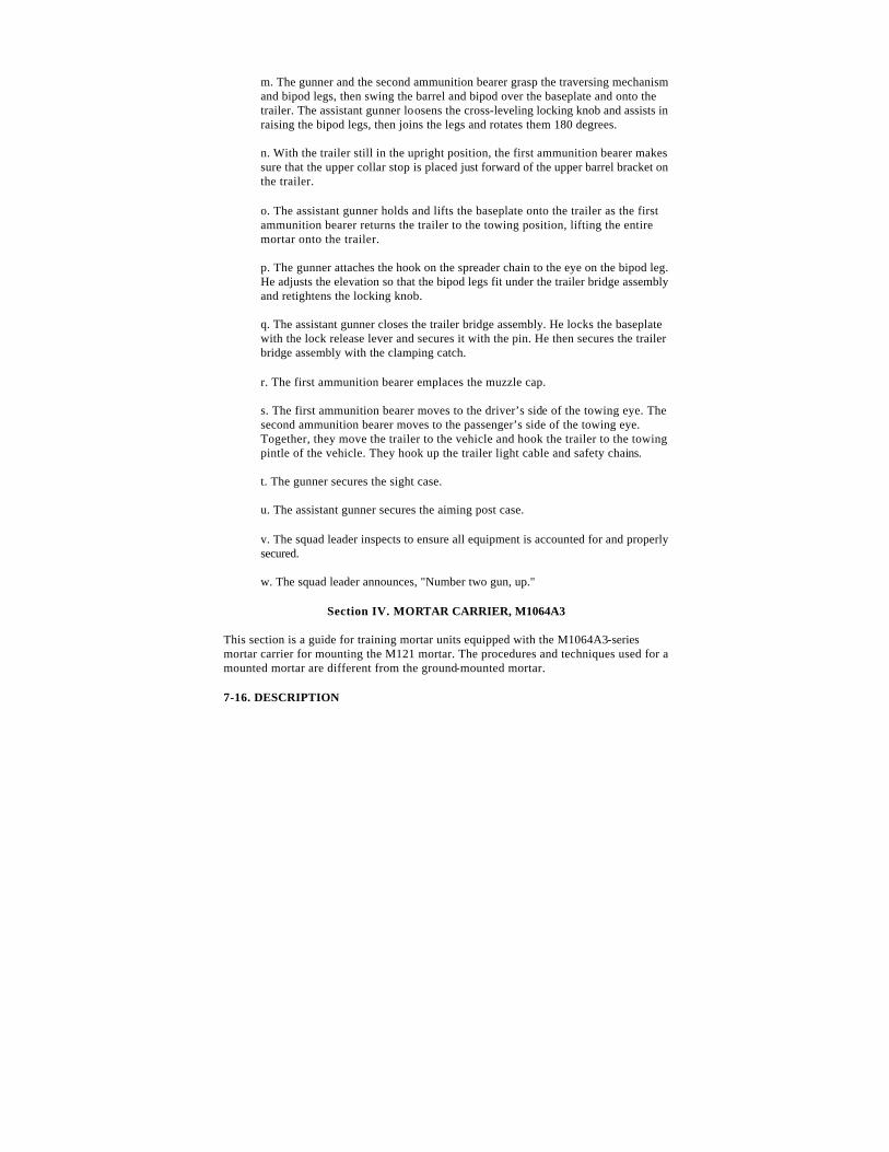
m. The gunner and the second ammunition bearer grasp the traversing mechanism and bipod legs, then swing the barrel and bipod over the baseplate and onto the trailer. The assistant gunner loosens the cross-leveling locking knob and assists in raising the bipod legs, then joins the legs and rotates them 180 degrees.
n. With the trailer still in the upright position, the first ammunition bearer makes sure that the upper collar stop is placed just forward of the upper barrel bracket on the trailer.
o. The assistant gunner holds and lifts the baseplate onto the trailer as the first ammunition bearer returns the trailer to the towing position, lifting the entire mortar onto the trailer.
p. The gunner attaches the hook on the spreader chain to the eye on the bipod leg. He adjusts the elevation so that the bipod legs fit under the trailer bridge assembly and retightens the locking knob.
q. The assistant gunner closes the trailer bridge assembly. He locks the baseplate with the lock release lever and secures it with the pin. He then secures the trailer bridge assembly with the clamping catch.
r. The first ammunition bearer emplaces the muzzle cap.
s. The first ammunition bearer moves to the driver’s side of the towing eye. The second ammunition bearer moves to the passenger’s side of the towing eye. Together, they move the trailer to the vehicle and hook the trailer to the towing pintle of the vehicle. They hook up the trailer light cable and safety chains.
t. The gunner secures the sight case.
u. The assistant gunner secures the aiming post case.
v. The squad leader inspects to ensure all equipment is accounted for and properly secured.
w. The squad leader announces, "Number two gun, up."
Section IV. MORTAR CARRIER, M1064A3
This section is a guide for training mortar units equipped with the M1064A3-series mortar carrier for mounting the M121 mortar. The procedures and techniques used for a mounted mortar are different from the ground-mounted mortar.
7-16. DESCRIPTION
The M1064A3 carrier (Figures 7-7 and 7-8) is an M113A3 armored-personnel carrier modified to carry the 120-mm mortar, M121, on a specially designed mount. It is fully tracked, highly mobile, and armor protected. It can be transported by air and can be dropped, and it has fording capabilities in up to 40 inches of water.
Figure 7-7. Mortar carrier M1064A3, front and side view.
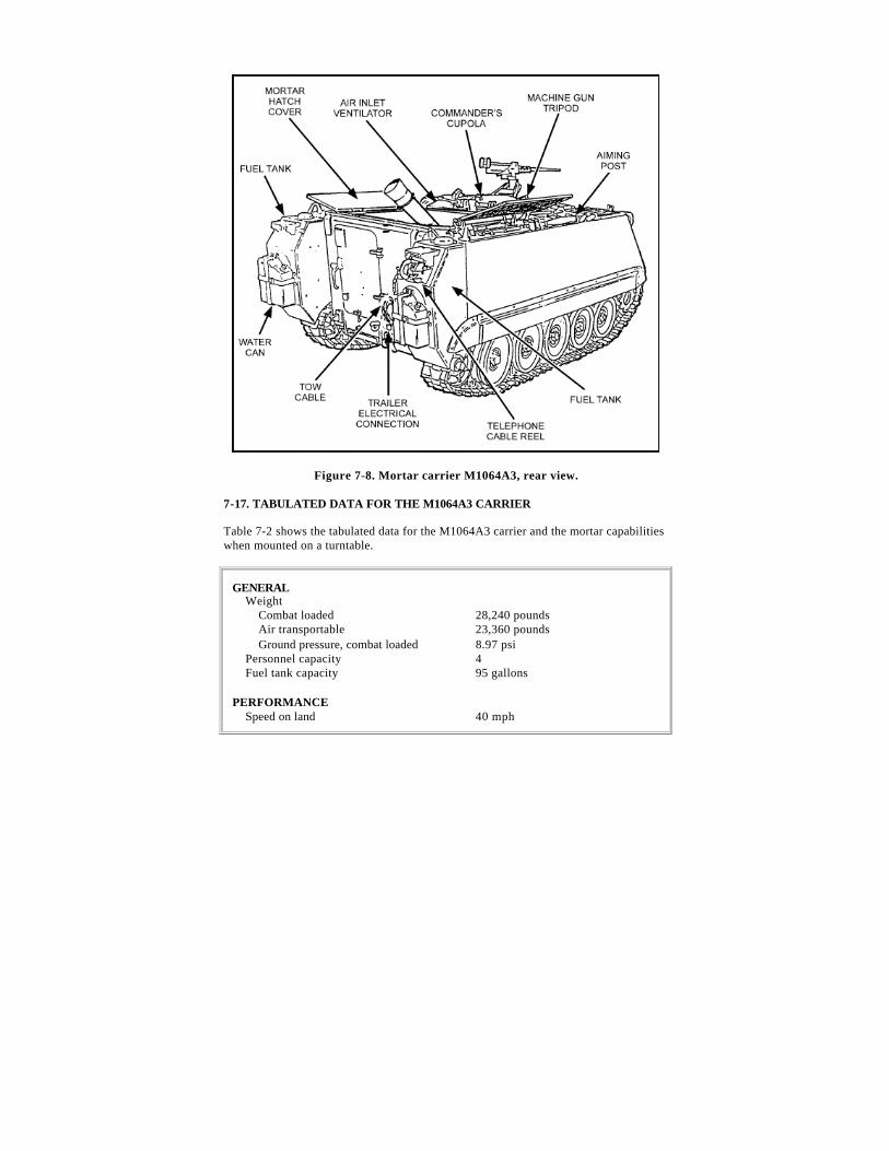
Figure 7-8. Mortar carrier M1064A3, rear view.
7-17. TABULATED DATA FOR THE M1064A3 CARRIER
Table 7-2 shows the tabulated data for the M1064A3 carrier and the mortar capabilities when mounted on a turntable.
GENERAL Weight Combat loaded Air transportable Ground pressure, combat loaded Personnel capacity Fuel tank capacity
28,240 pounds 23,360 pounds 8.97 psi 4 95 gallons
PERFORMANCE Speed on land Speed in water, with track
40 mph 3.6 mph
Speed in water, with track Cruising range Turning radius Slope Side slope Trench crossing Vertical wall climbing Gross horsepower-to-weight ratio
3.6 mph 300 miles Pivot to infinite 60 percent 40 percent 66 inches 24 inches 19.5 hp/ton
ENGINE Make and model Displacement Fuel Gross horsepower
Detroit diesel 6V53T 318 cubic inches Diesel 275
TRANSMISSION, AUTOMATIC Make and model Type Steering Brake type
RUNNING GEAR Suspension type Road wheels Track type Number of shoes Track pitch Track width Shock absorbers Wheel travel
Torsion bar 5 pairs per side, 24-inch diameter Steel single pin, detachable rubber pad 63 left, 64 right 6 inches 15 inches 3 per side 9.0 inches
ELECTRICAL SYSTEM Generator Amperes Volts, dc Batteries
200 28 4 type 6TL, 120 amp/hr, 12 volts each
ARMAMENT .50 caliber machine gun 120-mm mortar
2,000 ready rounds 69 ready rounds (45 horizontal, 24 vertical). Type of rounds carried depends on the tactical mission.
SQUAD WEAPONS Rifles, M16A2, 5.56-mm
4
ARMOR Hull
5083 Aluminum
FIRE EXTINGUISHERS Fixed Portable
5 pounds CO2 for engine compartment 5 pounds CO2
MORTAR CAPABILITIES MOUNTED ON TURNTABLE
TRAVERSING LIMITS Right of center with traverse extension Left of center with traverse extension
858 mils 808 mils
TOTAL TRAVERSE Capability from extreme left to extreme right Without traversing extension With traversing extension
1486 mils 1666 mils
ELEVATION LIMITS (LEVEL) Track maximum Track minimum
1510 mils 0800 mils
Table 7-2. Tabulated data for the M1064A3 carrier .
Section V. OPERATION OF A CARRIER-MOUNTED 120-mm MORTAR
The mortar section is the fire unit for the mortar platoon. When a position is occupied, mortars are emplaced 75 meters apart making the section front (distance between flank mortars) about 150 meters. The mortars are numbered 1, 2, and 3 (from right to left) when facing the direction of fire. The squad of the mortar carrier consists of four members--squad leader, gunner, assistant gunner, ammunition bearer/driver. The differences in the procedures from a ground-mounted mortar squad are also discussed in this section.
7-18. MORTAR AND VEHICULAR MOUNT
The mortar is carried while attached to its vehicular mount. A clamping support is provided to hold the mortar during travel. A bipod support assembly provides attachment mounting for the M191 bipod and secures it in a locking position during travel. The
breech socket provides a base in which the weapon rests. The mortar is provided with a sight extension arm assembly, which is received by the socket of the coupling and sight mount assembly. The gunner uses the sight extension arm to sight on his aiming point above the hull of the vehicle. The extension must be removed before moving the mortar to prevent wear on the sight mount’s coupling gears.
7-19. MAINTENANCE
Care and cleaning of the mortar, instruments, and equipment are the duty and responsibility of the mortar squad. Care and cleaning of the carrier-mounted mortar are the same as for the ground-mounted mortar. All maintenance records and lubricating procedures for the 120-mm mortar and the mount, M191, are located in TM 9-1015-250-10. For maintenance procedures for the M1064A3 carrier, see TM 9-2350-261-10.
7-20. PLACING A CARRIER-MOUNTED 120-mm MORTAR INTO ACTION
To place the mortar into action, the crew performs the following actions upon the squad leader’s command, ACTION.
Note : If the weapon system cannot be leveled at any elevation given, the gunner is authorized to go to high range (low range) and move the buffer housing assembly along the cannon between the circular white line and the lower collar stop without moving past the vertical position until the gun system can be leveled.
a. The gunner pulls the chain on the center cargo hatch releasing and folding it over onto the right hatch ensuring that the hatch locks into place. He then pulls the chain on the right cargo hatch releasing and folding it over and secures it.
b. Once the gunner has the center and right cargo hatch secured, the assistant gunner pulls the chain on the left cargo hatch releasing and folding the hatch over ensuring that it is locked into place.
c. The assistant gunner unlocks the clamping support assembly.
d. The gunner loosens the clamp handle assembly and grasps the buffer housing assembly and pulls it down until it is flush with the lower collar stop.
e. The gunner ensures the white line on the barrel is lined up with the white line on the buffer housing assembly. He then tightens the clamp handle assembly until a metallic click is heard. He places the weapon on FIRE with the "F" showing.
f. The assistant gunner then passes the sight extension to the gunner and removes the muzzle cover.
g. The gunner places the sight extension into the dovetail slot on the bipod and secures it.
h. The gunner mounts the sight onto the sight extension and places a deflection of 3200 mils and an elevation of 1100 mils onto the sight and levels the deflection bubble with the cross-leveling handwheel on the bipod.
i. The assistant gunner places the BAD onto the cannon and secures it and levels the elevation bubble.
j. The gunner then ensures that the traversing mechanism is within four turns of center, and the traversing extension is centered on the bipod.
k. When the gunner is satisfied that the mortar is mounted correctly, he announces, "Up" so that the squad leader can inspect the weapon system.
l. The carrier-mounted 120-mm mortar is now placed into action and ready to be reciprocally laid.
7-21. LAY FOR DEFLECTION AND ELEVATION ON A CARRIER-MOUNTED 120-mm MORTAR
Deflection and elevation are received from the fire direction center in the form of a fire command. If a deflection change is required, it will always precede the elevation change.
Note : Small deflection changes are greater than 20 mils but less than 60 mils. Small elevation changes are greater than 35 mils but less than 90 mils. Large deflection changes are greater than 200 mils but less than 300 mils. Large elevation changes are greater than 100 mils but less than 200 mils.
a. Small Deflection and Elevation Changes.
(1) The gunner is given a deflection and elevation change in the form of a fire command.
(2) As soon as the gunner receives the fire command, he places the data on the sight and elevates or depresses the mortar to "float" the elevation bubble.
(3) The gunner then looks into the sight to determine whether to traverse the mortar. He places his hand on the traversing handwheel and traverses one-half the distance to his aiming poles.
(4) The gunner cross-levels his deflection bubble with the cross-level handwheel on the bipod.
(5) The gunner repeats steps (3) and (4) until the vertical cross line is within 2 mils of the left edge of the aiming posts and his deflection bubble is leveled.
(6) The gunner levels his elevation bubble with the elevation handwheel on the bipod.
(7) The gunner rechecks his data and bubbles to ensure the proper lay of the weapon system.
b. Large Deflection and Elevation Changes.
(1) The deflection and elevation are received from the FDC in the form of a fire command. If a deflection change is required, it precedes the elevation change.
Note : Large deflection changes are greater than 200 mils but less than 3000 mils. Large elevation changes are greater than 100 mils but less than 200 mils. This may require the buffer housing assembly to be moved up on the cannon. Ensure the bipod is not forward of the vertical position.
(2) Lay for large deflection and elevation change.
(a) The mortar is mounted and the sight is laid on the aiming posts with a deflection and an elevation.
(b) The gunner is given a deflection and an elevation change in the form of a fire command.
(c) As soon as the gunner receives the fire command, he places the data on the sight, and elevates or depresses the mortar to "float" the elevation bubble. The assistant gunner is allowed to "dead level" the elevation bubble.
(d) If in low range, the gunner unlocks the low-range support latch. With his left hand on the bipod leg and his right hand on the traversing mechanism, and with the assistant gunner’s right hand on the bipod leg and his left hand on the traversing mechanism, together they raise the bipod into high range.
(e) The assistant gunner inserts the high-range locking pin to secure the bipod.
(f) If in high range, the gunner pulls the high-range locking pin. With his left hand on the bipod leg and his right hand on the traversing mechanism,
and with the assistant gunner’s right hand on the bipod leg and his left hand on the traversing mechanism, together they lower the bipod into low range.
(g) The gunner then looks into his sight to determine if he has to shift the mortar and announces to the assistant gunner, "Unlock the turntable."
(h) With the assistant gunner’s help, the gunner looks through his sight and shifts the mortar until the vertical cross line is aligned with the aiming poles.
(i) The gunner cross-levels his deflection bubble. Once leveled, he looks into the sight to determine if he is still within 20 mils of his aiming posts. If the vertical cross line is still within 20 mils of the aiming posts, the gunner announces to the assistant gunner, "Lock it" (referring to locking the turntable).
(j) With the turntable in the locked position, the gunner continues to traverse and cross-level until the vertical cross line is lined up with the aiming posts, and the deflection bubble is level.
(k) The gunner levels the elevation bubble. Before the gunner announces, "Gun up," he rechecks his data, bubbles, and four turns of center.
(3) When the mortar is traversed more than 60 mils left or right from center, a compensated sight picture occurs. To correct this, the rule to follow is "hey-diddle-diddle-far-pole-in-the-middle."
7-22. PERFORMING MISFIRE PROCEDURES ON AN M121 CARRIER-MOUNTED 120-mm MORTAR DURING COMBAT
The barrel assembly of the carrier-mounted 120-mm mortar must be at its lowest elevation to perform misfire procedures. However, crews must never change from high range to low range. When a misfire occurs, all crew members (or the crew member that first notices) shout, "Misfire."
WARNING
To avoid possible injury to the crew, do not change the range of the mortar (from high to low or from low to high). Do not stand in front of or behind the barrel.
a. At the announcement of "Misfire," all crew members remain with the mortar.
Note : During peacetime live-fire exercises, all crew members except the gunner leave the firing position and move at least 100 meters to the rear of the mortar position. All crew members will exit the carrier through the cargo hatches, climbing over the front of the carrier, and will return the same way.
b. The gunner stands to the right or left rear of the mortar and kicks the barrel several times. If the round does not fire after kicking the barrel, the gunner moves to where the rest of the crew is and waits for one minute. (This 1-minute wait allows the round time to fire should there be a delayed action [hangfire] of the propelling charge.) After the 1-minute wait, the gunner performs the following:
(1) He checks the barrel for heat using his bare hands. Starting at the muzzle, he lightly touches the barrel with his fingertips every few inches down to the breech cap. If the barrel is too hot, the crew uses some means (such as water or snow) to cool it down before attempting to remove the misfire.
(2) If the barrel is cool enough to handle, the gunner places the weapon on SAFE with the "S" showing.
c. The gunner locks the data down on the sight unit, removes the sight and places it in a safe place, and calls the crew forward.
d. The driver/ammunition bearer mounts the carrier from the front and lowers the ramp.
e. The gunner then depresses the barrel to its lowest elevation using the elevation handwheel, leaving about 1/4 inch of sleeve showing (so there is no metal to metal contact).
CAUTION
At no time will the clamp handle assembly be loosened (except during jammed or stuck rounds).
f. The assistant gunner removes the blast attenuator device and places it aside. He secures the staff assembly with the extractor attached. He rotates it forward, stabilizing the extractor, and inserts the extractor into the cannon. He lowers it slowly into the cannon (hand over hand) until the extractor makes contact with the round. He rotates the extractor in either direction until he feels the detent pins connect into the round. He continues rotating until resistance is felt.
g. The assistant gunner lifts up slightly on the extractor to ensure it has connected with the round. He continues lifting the extractor until the body of the round
appears at the muzzle. At this time, the gunner grasps the round and assists in removing the round. Once the round has cleared the cannon, the extractor with staff assembly and round is guided between the cannon and the cross-member. The gunner and assistant gunner move under the cross-member and down the ramp to the opposite side of the ammunition point at the rear of the carrier.
Note : Due to the weight of the round, the gunner may assist during the entire extraction process.
CAUTION
Once the assistant gunner ensures the extractor is firmly connected with the round, he extracts the round in one steady motion (using the hand-over-hand process) without stopping or lowering the round.
Note : If the round cannot be removed with the extractor, the assistant gunner kneels on the ramp to stabilize the bipod. The gunner places his left hand under the cannon and loosens the clamp assembly until the buffer housing assembly falls free from the cannon. The assistant gunner lowers the bipod to the ramp. The gunner and ammunition bearer lift the cannon to approximately a 60-degree angle and rotate the cannon until the white line is on the bottom. Together, they lift the cannon from the breech socket assembly and carry it to the dud pit. Ensuring the cannon remains pointed down range, the platoon leader or platoon sergeant notifies EOD personnel. (At no time will the cannon be lifted over or rested on the carrier’s cross-member. The cannon MUST be taken under the cross-member.)
h. Once the gunner and assistant gunner have cleared the ramp, the ammunition bearer comes forward and stands beside the gunner.
i. With the assistant gunner holding the round extractor by the handle and the gunner holding the round, the ammunition bearer presses on all four catches on the extractor at the same time, releasing the round from the extractor.
j. The gunner inspects the round. If the primer has been struck by the firing pin, the round is disposed of in accordance with range SOP. If no contact was made with the firing pin, action is taken to clean any possible obstructions inside the barrel.
Note : Nondevelopment item (NDI) ammunition will not be refired.
k. The assistant gunner swabs the bore and the gunner places the safety mechanism on "F" (FIRE).
l. The gunner re-installs the sight, re-lays the mortar, and continues the mission.
Note : If the extractor cannot grasp the round, use another extractor if possible. If the extractor still cannot grasp the round, follow steps m through r.
m. The gunner holds the cannon near the muzzle and the assistant gunner holds the bipod assembly. The gunner opens the buffer housing assembly.
n. The gunner and ammunition bearer turn the cannon until the white line is in the down position and carefully remove the cannon from the breech cap socket.
o. Keeping the cannon horizontal and pointing in the direction of fire, the gunner and ammunition bearer move the cannon to the opposite side of the ammunition point. The assistant gunner places the ends of his thumbs over the edges of the muzzle, grasping the cannon with his fingers.
p. At the assistant gunner’s command of LIFT, the ammunition bearer lifts the cannon’s breech cap assembly causing the round to slide down to the assistant gunner’s hands. The assistant gunner removes the round, inspects it, tries to replace the safety wire (if applicable), places the round in the dud pit, tags the round, and notifies EOD.
q. The assistant gunner swabs the bore.
r. The gunner re-lays the mortar and continues the mission.
Note : If the round is grasped but cannot be removed, follow steps s through u.
s. The gunner holds the cannon near the muzzle, and the assistant gunner holds the bipod assembly. The gunner opens the buffer housing assembly.
t. The gunner and ammunition bearer turn the cannon until the white line is n the down position and carefully remove the cannon from the breech cap socket.
u. Keeping the cannon horizontal and pointing in the direction of fire, the gunner and ammunition bearer lift the cannon (with the extractor still attached to the round) and carry it to the dud pit, ensuring it remains pointing downrange. The platoon leader or platoon sergeant notifies EOD.
7-23. MOUNTING OF THE MORTAR FROM A CARRIER TO A GROUND-MOUNTED POSITION
The procedures for placing the mortar into action by mounting it from a carrier to a ground-mounted position are described below.
Note : Left and right are in relation to the mortar’s direction of fire.
a. The driver lowers the ramp and dismounts the mortar from the carrier.
b. The gunner pulls down on the chain for the center hatch and folds it over, then secures it to the right cargo hatch. He pulls down on the chain for the right cargo hatch and folds both hatches over, then secures them in place. The assistant gunner pulls down on the chain for the left cargo hatch and folds it over, then secures it in place.
c. The squad leader dismounts the carrier and shows the crew where he wants the mortar to be mounted and indicates the direction of fire.
d. The driver/ammunition bearer and assistant gunner release the baseplate by removing the safety pin and pushing the handle up. Together they tilt the baseplate out and lift it from the lower brackets.
e. They place the baseplate at the firing position while the gunner retrieves the sight and aiming posts and places them on the left side of the baseplate.
f. The assistant gunner holds the bipod while the gunner unlocks the clamp handle assembly. The assistant gunner lowers the bipod until it rests on the ramp. At the same time, the driver/ammunition bearer assembles the aiming posts.
g. The assistant gunner releases the safety pins and rotates the handles until the arrows are facing each other and then pulls the handles out, releasing the bipod.
h. The assistant gunner installs the bipod leg extensions onto the bipod and secures them with the safety pins.
i. The assistant gunner and driver/ammunition bearer secure the bipod and carry it to the firing position. They place it about 2 feet in front of the baseplate.
CAUTION
Damage may occur to the turntable socket if the following procedures are not followed.
j. The driver/ammunition bearer removes the muzzle plug while the gunner releases the clamping support assembly. Together they raise the barrel to a 60-degree angle and rotate it until the white line is facing the turntable. They then lift straight up removing the barrel from the socket.
k. The gunner and driver/ammunition bearer carry the barrel to the baseplate. With the white line on the barrel facing the ground, they tilt the barrel to a 60-degree angle. They carefully insert the barrel into the baseplate socket. They rotate the barrel until the white line is facing skyward and then lower it onto the buffer housing assembly ensuring the white line on the barrel aligns with the white line on the buffer housing assembly. The gunner then slides the buffer housing assembly down the barrel until it is flush with the lower collar stop on the barrel.
l. The gunner tightens the clamp handle assembly until a metallic click is heard.
m. The gunner places the safety mechanism on FIRE with the "F" showing.
n. The gunner places the sight on the weapon and indexes a deflection and elevation.
7-24. TAKING THE MORTAR OUT OF ACTION (GROUND-MOUNTED TO M1064A3 CARRIER-MOUNTED)
The procedures for mounting the mortar on the carrier from a ground-mounted position are described below.
a. The squad leader commands, OUT OF ACTION, PREPARE TO MARCH.
b. The gunner places the weapon on SAFE with the "S" showing.
c. The gunner places a deflection of 3200 mils and an elevation of 0800 mils on the M67 sight.
d. The gunner removes the sight from the dovetail slot. He places the sight in the sight case and secures it on the carrier.
e. The gunner then replaces the sight mount cover and snaps it.
f. The ammunition bearer retrieves the Ml4 aiming posts and the M58 and M59 aiming post lights and stows them on the carrier.
g. The assistant gunner kneels down and secures the bipod and lowers it to its lowest elevation leaving about one-quarter of a turn of the shaft showing.
h. The gunner opens the buffer housing assembly with his left hand while securing the barrel assembly with his right hand.
i. The gunner and ammunition bearer rotate the barrel assembly until the white line is on the bottom. They raise the barrel to about a 60-degree angle and lift it from the baseplate socket. They carry the barrel assembly to the carrier.
j. The gunner and ammunition bearer make sure the clamping support assembly is open. They ensure the bipod support assembly is in the low-range position and the turntable is centered and locked.
k. The gunner and ammunition bearer position the mortar barrel assembly just above the clamping support assembly with the white line facing down.
l. The gunner and ammunition bearer carefully insert the breech cap ball into the socket. They raise the mortar barrel assembly and rotate it until the white line is in the up position. They install the muzzle plug and lower the mortar barrel assembly onto the clamping support assembly and lock it.
m. The assistant gunner takes the bipod assembly to the carrier.
n. The assistant gunner rests the bipod assembly on the carrier ramp with the cross-leveling mechanism pointing toward the gunner’s position.
o. The assistant gunner removes pins and leg extensions from the bipod legs and stows them in the step.
p. The assistant gunner removes the handles from the bipod support assembly. He ensures the arrows are facing each other.
q. The assistant gunner slides the bipod legs onto the attaching slot on the bipod support assembly.
r. With the arrows facing each other and the holes matching, the assistant gunner inserts the handles through the bipod support assembly slot and legs. He turns the handles so that the arrows point toward the bipod legs and attaches the safety pins.
s. The assistant gunner slides the buffer housing assembly up along the barrel assembly until it stops. He tightens the clamp handle assembly until he hears a metallic click.
t. The assistant gunner and ammunition bearer carry the baseplate to the carrier,
u. The assistant gunner and ammunition bearer make sure the pin is removed and the handle is up.
v. The assistant gunner and ammunition bearer lift the baseplate with the spades away from the carrier and place the two corners without handles inside the rims of the lower brackets.
w. The assistant gunner and ammunition bearer tilt the baseplate toward the carrier and pull the handle down and lock it with the pin.
x. The squad leader inspects to ensure all equipment is accounted for and properly secured.
y. The squad leader announces, "Number two gun up and prepared for march."
7-25. PERFORMING SAFETY CHECKS ON A CARRIER-MOUNTED 120-mm MORTAR
Specific safety checks must be performed before firing mortars. Most can be made visually. The gunner is responsible for physically performing the checks under the squad leader’s supervision.
Note : The buffer housing assembly may need to be adjusted to complete this task.
a. The gunner checks for mask and overhead clearance.
(1) To determine mask clearance, the gunner places an elevation of 0800 on the sight and lowers the barrel until the elevation bubble is level. He places his head against the breech cap and sights along the barrel to see if any obstructions are in front of the mortars. With the gunner’s head still against the breech cap, the assistant gunner traverses the mortar through its full range of traverse (traversing extension) to ensure that no obstructions are in front of the mortar.
(2) To determine overhead clearance, the gunner places an elevation of 1500 on the sight and raises the barrel until the elevation bubble is level. He places his head against the breech cap and sights along the barrel to see if any obstructions are in front of the mortar. With the gunner’s head still against the breech cap, the assistant gunner moves the mortar through its full range of traverse (traversing extension) to ensure that no obstructions are in front of the mortar.
Note : If obstructions are found at any point in the full range of traverse or elevation, then the mortar is not safe to fire. (In a combat situation, it may be necessary to fire the mortar from that position; if this is the situation, traverse and or elevate the mortar until it clears the obstruction. Level the sight by using the elevation micrometer knob. Record the deflection and elevation where the mortar clears the obstruction and report this information to the FDC.)
b. The gunner checks to ensure the breech assembly is locked in the turntable socket and the white line on the cannon bisects the white line on the buffer housing assembly.
c. The gunner checks to ensure the M191 bipod assembly is locked to the turntable mount and the arrows on the mount handles are pointed down (vertical).
d. The gunner checks to ensure the safety pins are installed,
e. The gunner ensures that the buffer housing assembly is secured to the cannon by loosening the clamp handle assembly about one-quarter of a turn and tightening the clamp handle assembly until a metallic click is heard.
f. The gunner ensures the cross-leveling locking knob is hand tightened.
g. The gunner checks the bipod support assembly to ensure it is locked in the high or low position and the safety pin is installed.
h. The gunner checks to ensure the turntable is in the locked position.
i. The gunner checks to ensure the cargo hatches are open and locked.
j. The gunner checks to ensure the blast attenuator device locking knob is hand tightened.
k. The gunner checks to ensure the safety selector is in the FIRE position with the "F" showing.
l. Ensure the bipod is not forward of the vertical position.
7-26. RECIPROCALLY LAYING THE MORTAR CARRIER SECTION
To reciprocally lay the mortar, follow the procedures discussed herein.
a. The aiming circle (AC) operator lays the vertical cross line on the mortar sight and announces, "Aiming point this instrument."
b. The gunner refers the sight (using the deflection micrometer knob) to the aiming circle with the vertical cross line, splitting the lens of the aiming circle, and announces, "Number (number of gun) gun, aiming point identified."
c. The AC operator turns the azimuth micrometer knob of the aiming circle until the vertical cross lines are laid on the center of the gun sight lens. He reads the deflection micrometer scales and announces, "Number (number of gun) gun, deflection, two three one five (2315)."
d. The gunner indexes the deflection announced by the AC operator on the sight and re-lays on the center of the AC lens by telling the driver to start the carrier. Looking through the sight, he tells the driver which direction to move the carrier (if necessary) and cross-levels. He ensures he has a correct sight picture (cross line splitting the AC lens), and the elevation and deflection bubbles are leveled. Once he has accomplished this, he announces, "Number (number of gun) gun, ready for recheck."
e. The AC operator gives the new deflection, and the process is repeated until the gunner announces, "Number (number of gun) gun, zero mils (or one mil); mortar laid."
f. As the squad announces, "Mortar laid," the AC operator commands the squad to give its referred deflection (normally 2800) and to place out aiming posts.
g. The gunner turns the deflection micrometer knob only and indexes a deflection of 2800 mils on his sight without disturbing the lay of the mortar.
h. The ammunition bearer runs with the aiming posts along the referred deflection about 100 meters from the mortar, dropping one post halfway (about 50 meters).
i. Once the far aiming post is placed out as described, the gunner uses arm-and-hand signals to guide the ammunition bearer to place out the near aiming post.
j. Once the correct sight picture is obtained, the gunner announces, "Number (number of gun) gun, up."
Section VI. AMMUNITION
Ammunition that can be fired by the 120-mm or 121-mm mortar are identified and described herein.
7-27. CLASSIFICATION
Ammunition is classified according to use. High explosive is used against personnel (in the open or in bunkers), light vehicles, and light bunkers. White phosphorus is used for screening and spotting. Illumination is used for battlefield illumination and signaling.
7-28. AUTHORIZED CARTRIDGES
The M929 smoke, M934 HE, and M933 HE cartridges are authorized to be fired from the M120 towed 120-mm mortar and the M121 carrier-mounted 120-mm mortar. The M57 HE, M91 illumination, and M68 smoke cartridges are authorized to be fired from a ground-mounted 120-mm mortar ONLY.
WARNING
Firing the M57, M68, or M91 120-mm cartridges from the M121 carrier-mounted mortar may cause bodily injury and hearing loss. These cartridges are not authorized to be fired from the carrier.
Note : 1. When using enhanced ammunition, the bursting area of the round is 75 meters;
when using NDI ammunition, the bursting area of the round is 60 meters.
2. A minimum range of 200 meters at charge 0 (charge may vary in firing table and whiz wheel) applies to all rounds and fuzes.
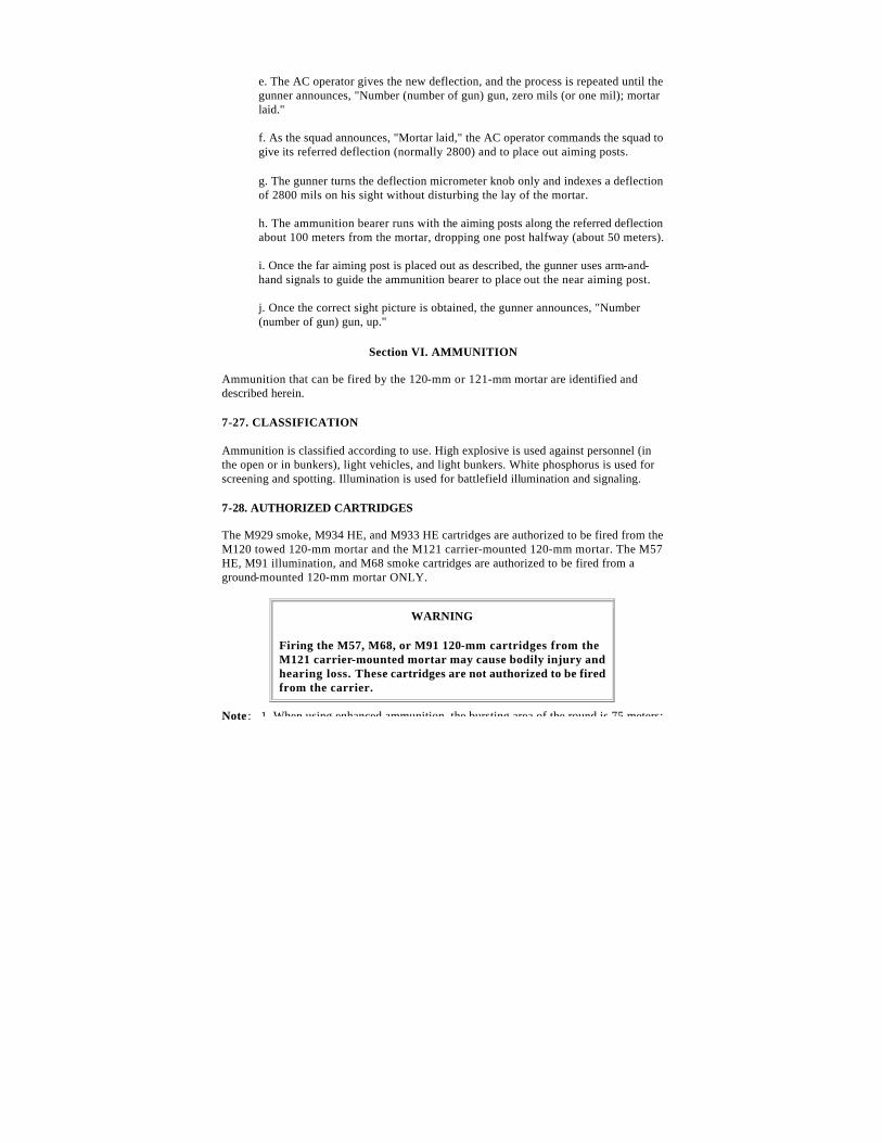
a. M57 HE Cartridge (NDI) (Figure 7-9).
Figure 7-9. M57 HE cartridge.
(1) Type and use: High explosive fragmentation and blast.
(2) Identification: Olive drab with yellow markings.
(3) Components: M935 point detonating (PD) fuze.
(4) Maximum range: 6,300 meters at charge 8; 7,200 meters at charge 10.
(5) Remarks: Used against personnel (in open or in bunkers), light vehicles, and light bunkers; weight to 20 pounds (13.18 kilograms).
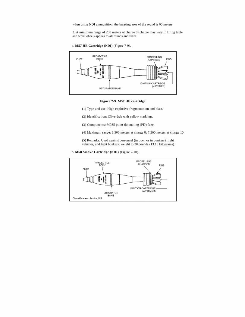
b. M68 Smoke Cartridge (NDI) (Figure 7-10).
Figure 7-10. M68 smoke cartridge.
(1) Identification: Light green with red markings.
(2) Components: M935 PD fuze.
(3) Maximum range: 6,300 meters at charge 8; 7,200 meters at charge 10.
(4) Remarks: Used for screening and spotting.
WARNING
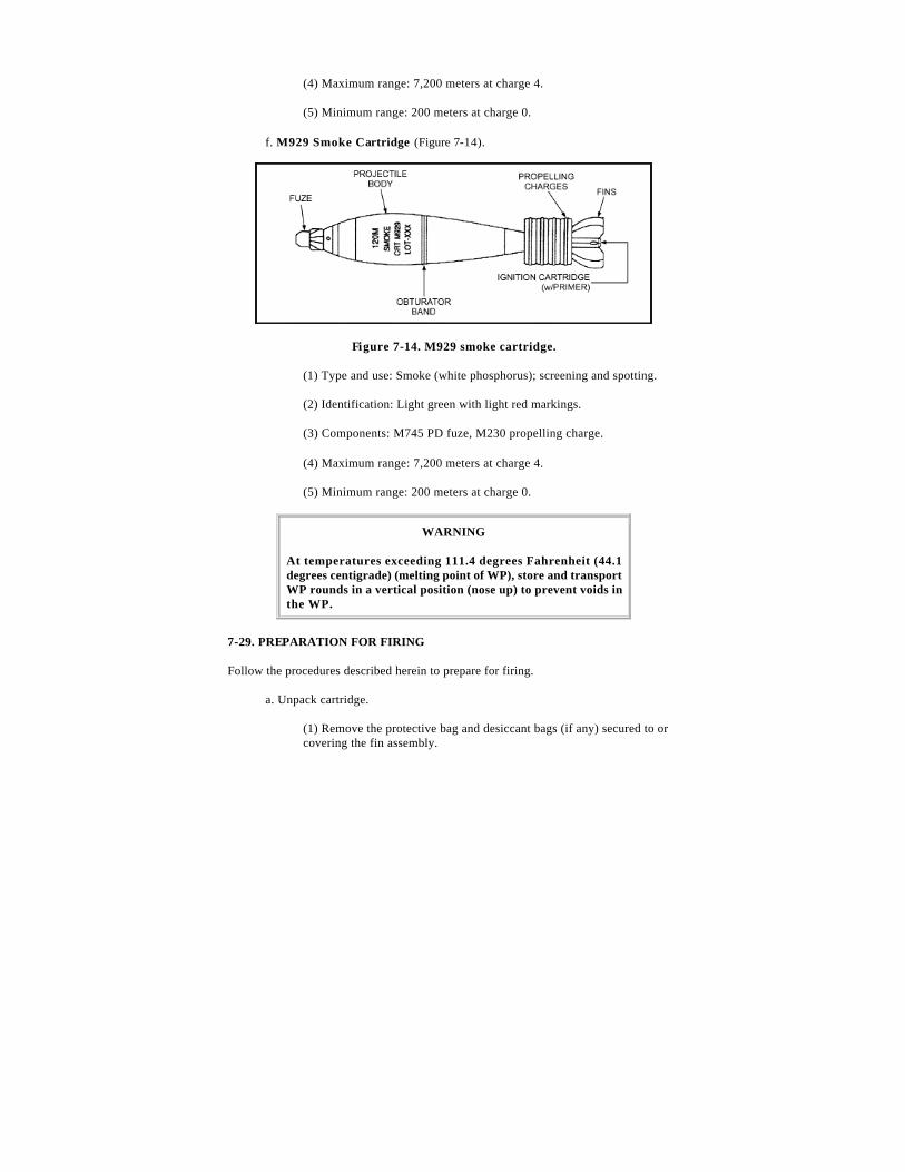
At temperatures exceeding 111.4 degrees Fahrenheit (44.1 degrees centigrade) (melting point of WP), store and transport WP rounds in a vertical position (nose up) to prevent voids in the WP.
c. M91 Illumination Cartridge (NDI) (Figure 7-11).
Figure 7-11. M91 illumination cartridge.
(1) Identification: White with black markings.
(2) Components: M776 (DM93) mechanical time superquick (MTSQ) fuze.
(3) Maximum range: 6,200 meters at charge 8; 7,100 meters at charge 10.
(4) Remarks: Contains candle and parachute used for illumination (weight to 29 pounds [13.18 kilograms]); burn time--46 to 60 seconds; candle power--1,000,000.
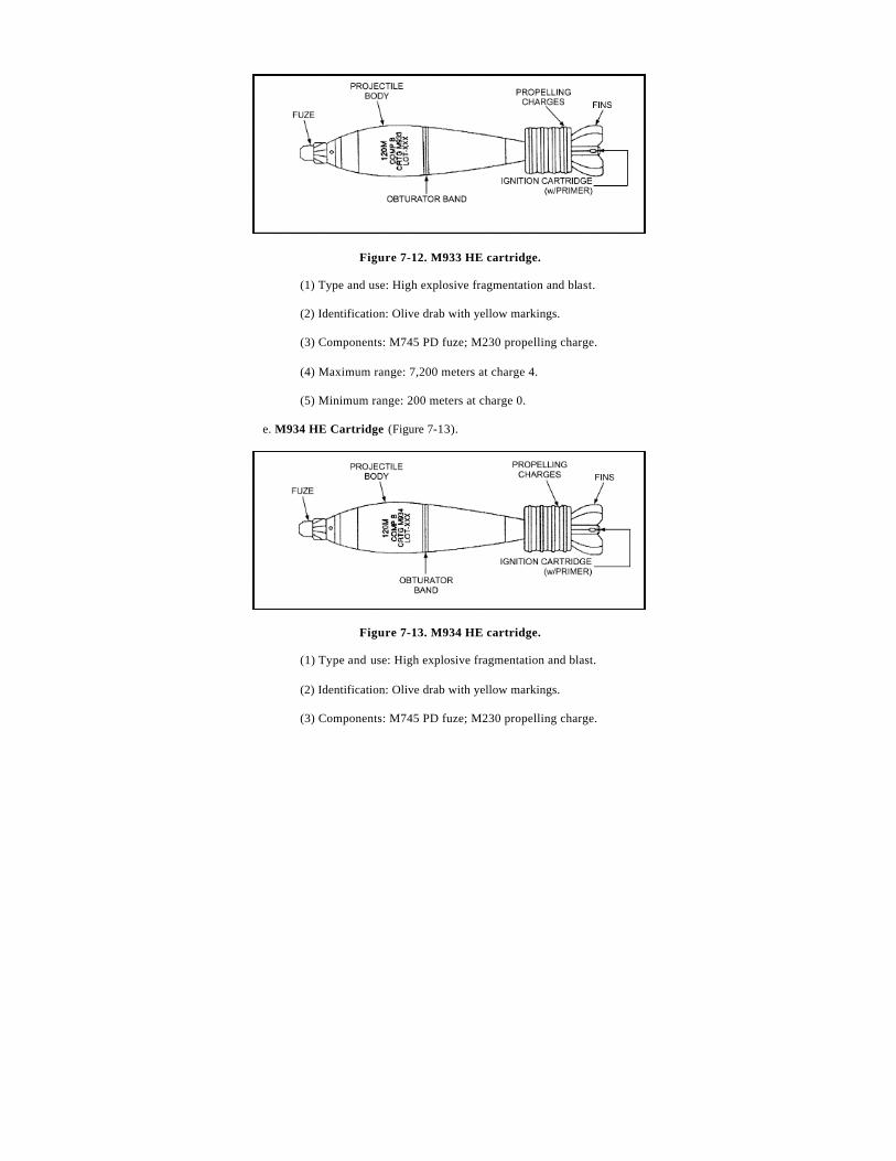
d. M933 HE Cartridge (Figure 7-12).
Figure 7-12. M933 HE cartridge.
(1) Type and use: High explosive fragmentation and blast.
(2) Identification: Olive drab with yellow markings.
At temperatures exceeding 111.4 degrees Fahrenheit (44.1 degrees centigrade) (melting point of WP), store and transport WP rounds in a vertical position (nose up) to prevent voids in the WP.
7-29. PREPARATION FOR FIRING
Follow the procedures described herein to prepare for firing.
a. Unpack cartridge.
(1) Remove the protective bag and desiccant bags (if any) secured to or covering the fin assembly.
Note : Examine the fin assembly for visible damage or looseness. Examine the fuzes and propelling charges for visible damage. Tighten loose fin assemblies (by hand) before firing. Cartridges with damaged (bent) fin assemblies, fuzes, or propelling charges will be turned in to the ammunition supply point as unserviceable.
(2) Remove the plastic shell or insert assembly (if any) covering the propelling charge.
b. Set the fuze for the required time or desired type of burst.
c. Adjust the propelling charge for desired range.
d. Remove or pull the safety wires (just before loading and firing the cartridge).
7-30. LOADING AND FIRING
Follow the procedures described herein to load and fire the 120-mm mortar.
a. Check to ensure that the cartridge has the proper amount of charge.
b. Remove the safety wire or clip (if any) before firing.
WARNINGS
1. Always check the mask and overhead clearance before firing.
2. PD and proximity fuzes may prematurely function when fired through extremely heavy rainfall.
3. Do not fire ammunition in temperatures above +146 degrees Fahrenheit (+63 degrees centigrade) or below -28 degrees Fahrenheit (-33 degrees centigrade).
4. Short rounds and misfires can occur if an excessive amount of oil or water is in the barrel during firing.
5. Before loading the cartridge, ensure the barrel and cartridge are free of sand, mud, moisture, snow, wax, or other foreign matter.
6. Ensure that all packing materials (packing stops, supports, and plastic bags) are removed from the cartridge.
7. Any glue or other foreign substance adhering to the cartridge, particularly at or near the obturator band, must be removed. If the substance cannot be removed, the cartridge will not be fired.
7-31. UNFIRED CARTRIDGES
This paragraph describes the procedures to follow for unfired cartridges.
a. Replace the safety wire or clip, if removed from the fuze.
Note : If safety pins cannot be fully reinserted into the fuze, notify EOD.
b. Reset the fuze (see paragraph 7-35).
c. Reinstall the propellant increments so that the cartridge has a full charge in proper order.
Notes: 1. M57, M68, and M91 cartridges should have seven propellant increments. The proper order is one brown, two blue, and four white.
2. Do not mix propelling charge models or lots. Use original increments.
d. Install packing stop. Repack cartridge.
7-32. CARE AND HANDLING OF CARTRIDGES
This paragraph describes the procedures to follow to care for and handle cartridges.
a. Do not throw or drop live ammunition.
b. Do not break the moisture resistant seal of the ammunition container until the cartridges are to be fired.
c. Protect cartridges when removed from the ammunition container. Protect ammunition from rain and snow. Do not remove the plastic shell or insert assembly around the propelling charge until the propelling charge is to be adjusted. If protective bags were packed with the cartridge, cover the fin assembly and propelling charge to prevent moisture contamination. Stack cartridges on top of empty ammunition boxes or on 4 to 6 inches (10 to 15 centimeters) of dunnage. Cover cartridges with the plastic sheets provided.
d. Do not expose cartridges to direct sunlight, extreme temperatures, flame, or other sources of heat.
e. Cartridges must be shielded from small-arms fire.
f. Store WP-loaded cartridges at temperatures below 111.4 degrees Fahrenheit (44.1 degrees centigrade) to prevent melting of the WP filler. If this is not possible, WP-loaded cartridges must be stored fuze-end up so that WP will resolidify with the void space in the nose end of the cartridge (after temperature returns below 111.4 degrees Fahrenheit [44.1 degrees centigrade]). Failure to observe this precaution could result in rounds with erratic flight.
g. Store WP-loaded ammunition separate from other types of ammunition.
h. Notify EOD of leaking WP cartridges. Avoid contact with any cartridges that leak.
i. Protect the primer of cartridges during handling.
j. Do not handle duds other than when performing misfire procedures.
7-33. FUZES
The fuzes used with cartridges for the 120-mm mortar are described in the following paragraphs.
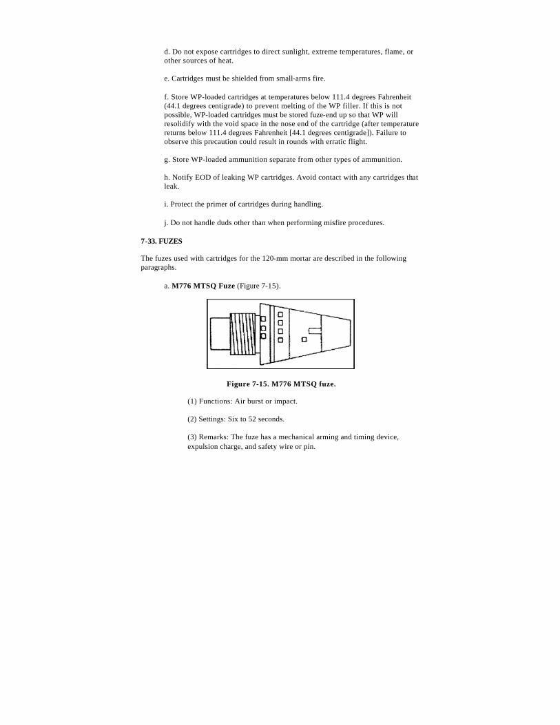
a. M776 MTSQ Fuze (Figure 7-15).
Figure 7-15. M776 MTSQ fuze.
(1) Functions: Air burst or impact.
(2) Settings: Six to 52 seconds.
(3) Remarks: The fuze has a mechanical arming and timing device, expulsion charge, and safety wire or pin.
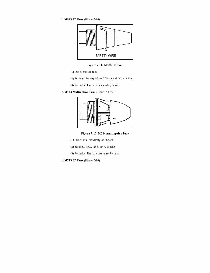
b. M935 PD Fuze (Figure 7-16).
Figure 7-16. M935 PD fuze.
(1) Functions: Impact.
(2) Settings: Superquick or 0.05-second delay action.
(3) Remarks: The fuze has a safety wire.
c. M734 Multioption Fuze (Figure 7-17).
Figure 7-17. M734 multioption fuze.
(1) Functions: Proximity or impact.
(2) Settings: PRX, NSB, IMP, or DLY.
(3) Remarks: The fuze can be set by hand.
d. M745 PD Fuze (Figure 7-18).
Figure 7-18. M745 PD fuze.
(1) Functions: Impact.
(2) Settings: None.
(3) Remarks: The fuze functions on impact with superquick action only. The markings (PRX, NSB, IIMP, and DLY) are dummy settings. Rotation of the fuze head does not alter the function mode.
7-34. SETTING FUZES
The following paragraphs describe how to set fuzes for different functions.
a. M935 PD Fuze (Figure 7-19).
Figure 7-19. Setting the M935 PD fuze.
(1) Superquick setting.
(a) These fuzes are shipped preset to function superquick on impact.
(b) Verify the setting before firing. The selector slot should be aligned with the SQ mark.
(2) Delay setting.
(a) Turn the selector slot in a clockwise direction until the slot is aligned with the DLY mark.
(b) Use a coin or a flat-tip screwdriver to change settings.
b. M776 (DM93) MTSQ Fuze (Figure 7-20).
Figure 7-20. Setting the M776 (DM93) MTSQ fuze.
(1) Rotate the head of the fuze to the left (counterclockwise) until the inverted triangle or index line is aligned with the correct line and number of seconds of the time scale.
(2) Use the fuze setter to rotate the head of the fuze.
Note : Once the desired setting has been passed, continue counterclockwise to reach the desired setting. Try to index the desired setting in as few rotations as possible.
(3) See the firing table for the correct time setting.
(4) Remove the fuze safety pin or wire before firing.
c. M745 PD Fuze. No setting is required. The fuze functions on impact with superquick action only. Disregard the markings (PRX, NSB, IMP, and DLY) on the fuze head.
d. M734 Multioption Fuze (Figure 7-21). Fuze can be set by hand by rotating the fuze head (clockwise) until the correct marking (PRX, NSB, IMP, or DLY) is over the index line.
Figure 7-21. Setting the M734 multioption fuze.
• PRX--Proximity. The fuze comes set to PRX. Burst height is 3 to 13 feet (1 to 4 centimeters).
• NSB--Near surface burst (nonjamming). Burst height is 0 to 3 feet (0 to 1 meter).
a. M935 PD Fuze. Align the selector slot with the SQ mark.
b. M776 MTSQ Fuze. Rotate the head of the fuze (counterclockwise) until the safe line (S or inverted triangle of the time scale) is aligned with the index line of the fuze body. Replace the safety wire.
c. M754 Multioption Fuze. Rotate the fuze head (counterclockwise) until the PRX marking is over the index line.