103
1141.1821.42-03- 1 Test and Measurement Division Operating Manual FM Measurement Demodulator for FSP FS-K7 1141.1796.02 Printed in the Federal Republic of Germany

1141.1821.42-03- 1
Test and MeasurementDivision
Operating Manual
FM Measurement Demodulator for FSPFS-K71141.1796.02
Printed in the FederalRepublic of Germany

FS-K7 Tabbed Divider Overview
1141.1821.42 RE E-2
Tabbed Divider Overview
Data Sheet
Safety InstructionsCertificate of QualityAddress of Support CenterList of R&S Representatives
Tabbed Divider
1 Chapter 1: Introduction
2 Chapter 2: Settings of the FM Demodulator
3 Chapter 3: Remote Control
4 Chapter 4: Index

1141.1821.42-03- 1
Test and MeasurementDivision
Operating Manual
FM Measurement Demodulator for FSPFS-K71141.1796.02
Printed in the FederalRepublic of Germany


FS-K7 Tabbed Divider Overview
1141.1821.42 RE E-2
Tabbed Divider Overview
Data Sheet
Safety InstructionsCertificate of QualityAddress of Support CenterList of R&S Representatives
Tabbed Divider
1 Chapter 1: Introduction
2 Chapter 2: Settings of the FM Demodulator
3 Chapter 3: Remote Control
4 Chapter 4: Index

FS-K7 Contents - Introduction
1141.1821.42 I-1.1 E-3
Contents – Chapter 1 "Introduction"
1 Introduction ..................................................................................................... 1.1Circuit Description - Block Diagrams.................................................................................. 1.1
Further Characteristics ......................................................................................................... 1.3IF Bandwidth....................................................................................................................... 1.3Demodulation Bandwidth.................................................................................................... 1.3AF Trigger........................................................................................................................... 1.4Stability of Measurement Results ....................................................................................... 1.4
FiguresFig 1-1 Block diagram of analyzer signal processing ..................................................................... 1.1
Fig 1-2 Block diagram of software demodulator ............................................................................. 1.2
Fig 1-3 Residual FM as a function of demodulation bandwidth...................................................... 1.4


FS-K7 Introduction
1141.1821.42 1.1 E-3
1 Introduction
The following chapters describe the new operating functions of the FM demodulator option for SpectrumAnalyzer FSP. In the case of functions identical to those of the base unit, reference is made to therelevant chapter in the base unit manual.
The digital signal processing in FSP, used in the analyzer mode for digital IF filters, is also ideally suitedfor demodulating FM or AM signals.
By sampling (digitization) already at the IF and digital downconversion to the baseband (I/Q), thedemodulator achieves maximum accuracy and temperature stability. There is no evidence of typicalerrors of an analog downconversion and demodulation like AM ⇔ FM conversion, deviation error,frequency response or frequency drift at DC coupling. Only the characteristics of the analog IF filterahead of the A/D converter need to be taken into consideration.
Circuit Description - Block Diagrams
Fig 1-1 Block diagram of analyzer signal processing shows the analyzer’s hardware from the IF to theprocessor. The IF filter is the resolution filter of the spectrum analyzer, with a bandwidth range from300 kHz to 10 MHz. The A/D converter samples the IF (20.4 MHz) at 32 MHz.
Lowpass filtering and reduction of the sampling rate follow the downconversion to the complexbaseband. The decimation depends on the selected demodulation bandwidth. The output sampling rateis set in powers of 2 between 15.625 kHz and 32 MHz. Useless oversampling at narrow bandwidths isavoided, saving computing time and increasing the maximum recording time.
The I/Q data is stored in memories each comprising 128 k words. The hardware triggering (external, IFpower) controls the memory.
I Memory128 k
Processor
Analog IF filter
Bandwidths300 kHz1 MHz3 MHz10 MHz
Analyzer IF20.4 MHz
AD
A/Dconverter
32 MHzsampling
clock
Digital down conversion+ decimation
cos
sin
decimationfilters
NCO20.4 MHz
Q Memory128 k
sampling rate32 MHz / 2n
n = 0 ... 11
Data aquisition hardware
I data
Q data
Trigger
Fig 1-1 Block diagram of analyzer signal processing
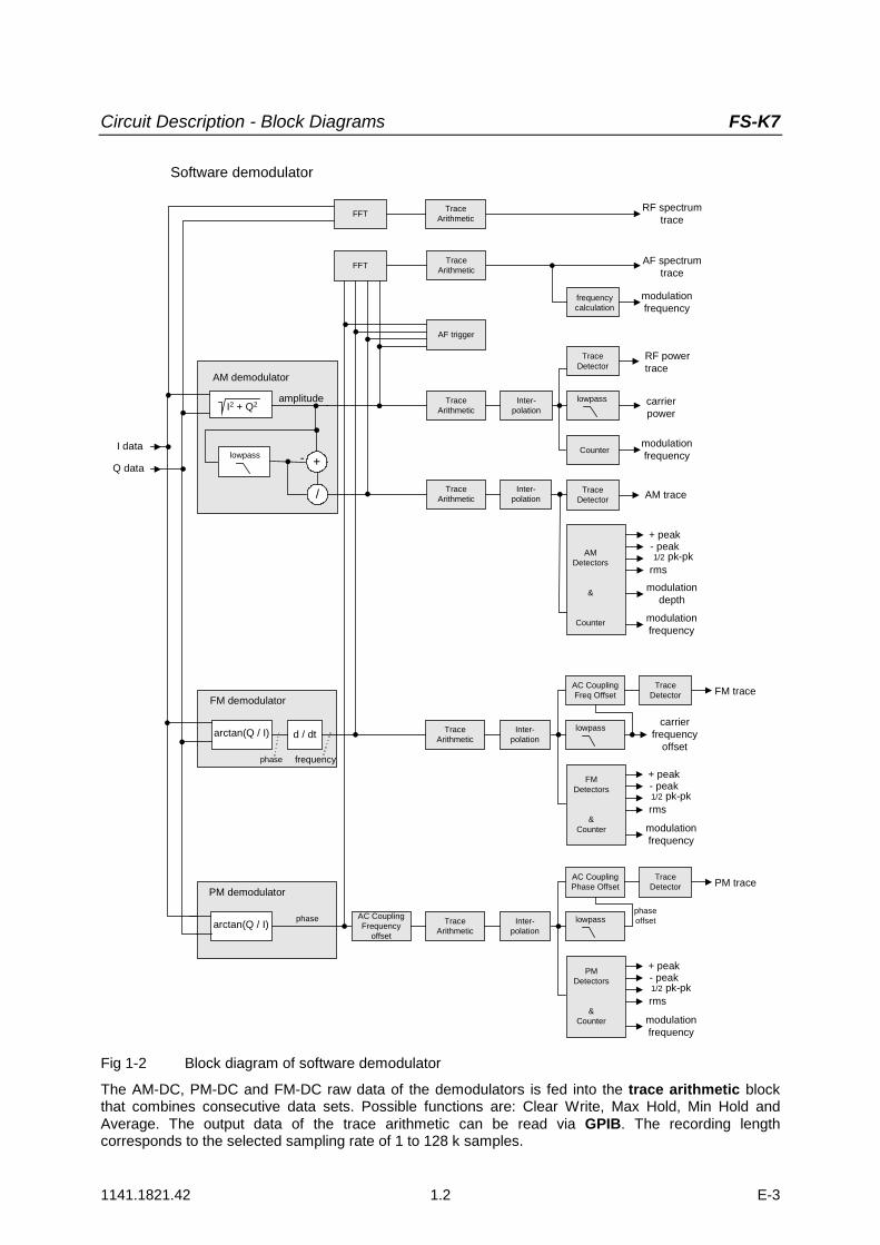
The software demodulator runs on the main processor of the analyzer. The demodulation process isshown in Fig 1-2 Block diagram of software demodulator. All calculations are performedsimultaneously with the same I/Q data set. Magnitude (= amplitude) and phase of the complex I/Q pairsare determined. The frequency result is obtained from the differential phase.
Circuit Description - Block Diagrams FS-K7
1141.1821.42 1.2 E-3
Software demodulator
Countermodulationfrequency
RF powertrace
carrierpower
lowpassInter-polation
Q data
FFTRF spectrum
trace
I2 + Q2
AM demodulator
amplitude
arctan(Q / I) d / dt
phase frequency
FM demodulator
I data
TraceDetector
TraceArithmetic
TraceArithmetic
PMDetectors
&Counter
+ peak
rms
- peak1/2 pk-pk
arctan(Q / I) phase
PM demodulator
Inter-polation
TraceArithmetic
modulationfrequency
lowpass
TraceDetector PM trace
AC CouplingFrequency
offset
AC CouplingPhase Offset
FMDetectors
&Counter
+ peak
rms
- peak1/2 pk-pk
Inter-polation
TraceArithmetic
modulationfrequency
lowpass
TraceDetector FM traceAC Coupling
Freq Offset
carrierfrequency
offset
phaseoffset
FFT AF spectrumtrace
TraceArithmetic
AF trigger
frequencycalculation
modulationfrequency
AMDetectors
&
Counter
+ peak
rms
- peak1/2 pk-pk
Inter-polation
TraceArithmetic
modulationfrequency
TraceDetector AM trace
modulationdepth
lowpass +-
/
Fig 1-2 Block diagram of software demodulator
The AM-DC, PM-DC and FM-DC raw data of the demodulators is fed into the trace arithmetic blockthat combines consecutive data sets. Possible functions are: Clear Write, Max Hold, Min Hold andAverage. The output data of the trace arithmetic can be read via GPIB. The recording lengthcorresponds to the selected sampling rate of 1 to 128 k samples.
FS-K7 Further Characteristics
1141.1821.42 1.3 E-3
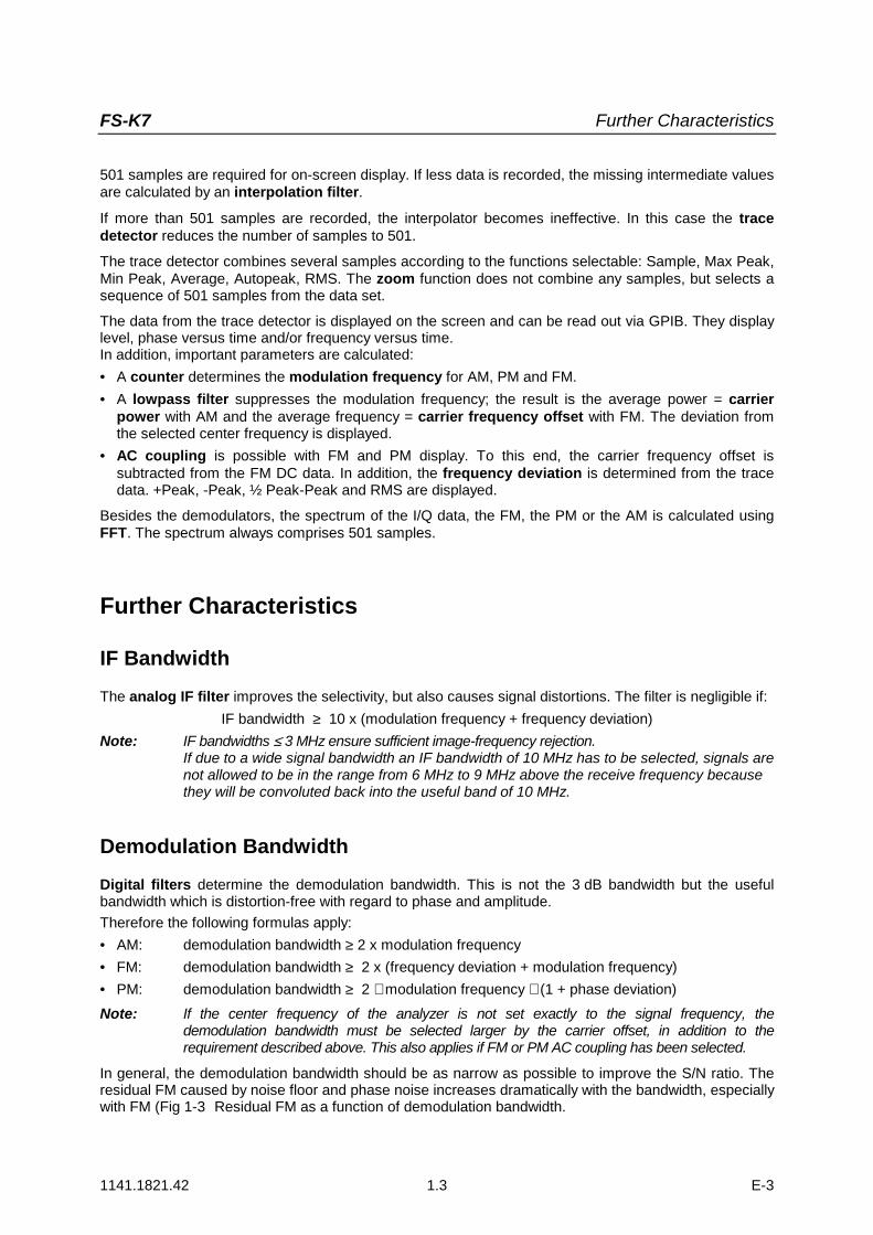
501 samples are required for on-screen display. If less data is recorded, the missing intermediate valuesare calculated by an interpolation filter.
If more than 501 samples are recorded, the interpolator becomes ineffective. In this case the tracedetector reduces the number of samples to 501.
The trace detector combines several samples according to the functions selectable: Sample, Max Peak,Min Peak, Average, Autopeak, RMS. The zoom function does not combine any samples, but selects asequence of 501 samples from the data set.
The data from the trace detector is displayed on the screen and can be read out via GPIB. They displaylevel, phase versus time and/or frequency versus time.In addition, important parameters are calculated:• A counter determines the modulation frequency for AM, PM and FM.• A lowpass filter suppresses the modulation frequency; the result is the average power = carrier
power with AM and the average frequency = carrier frequency offset with FM. The deviation fromthe selected center frequency is displayed.
• AC coupling is possible with FM and PM display. To this end, the carrier frequency offset issubtracted from the FM DC data. In addition, the frequency deviation is determined from the tracedata. +Peak, -Peak, ½ Peak-Peak and RMS are displayed.
Besides the demodulators, the spectrum of the I/Q data, the FM, the PM or the AM is calculated usingFFT. The spectrum always comprises 501 samples.
Further Characteristics
IF BandwidthThe analog IF filter improves the selectivity, but also causes signal distortions. The filter is negligible if:
IF bandwidth ≥ 10 x (modulation frequency + frequency deviation)Note: IF bandwidths ≤ 3 MHz ensure sufficient image-frequency rejection.
If due to a wide signal bandwidth an IF bandwidth of 10 MHz has to be selected, signals arenot allowed to be in the range from 6 MHz to 9 MHz above the receive frequency becausethey will be convoluted back into the useful band of 10 MHz.
Demodulation BandwidthDigital filters determine the demodulation bandwidth. This is not the 3 dB bandwidth but the usefulbandwidth which is distortion-free with regard to phase and amplitude.Therefore the following formulas apply:• AM: demodulation bandwidth ≥ 2 x modulation frequency• FM: demodulation bandwidth ≥ 2 x (frequency deviation + modulation frequency)• PM: demodulation bandwidth ≥ 2 ∗ modulation frequency ∗ (1 + phase deviation)Note: If the center frequency of the analyzer is not set exactly to the signal frequency, the
demodulation bandwidth must be selected larger by the carrier offset, in addition to therequirement described above. This also applies if FM or PM AC coupling has been selected.
In general, the demodulation bandwidth should be as narrow as possible to improve the S/N ratio. Theresidual FM caused by noise floor and phase noise increases dramatically with the bandwidth, especiallywith FM (Fig 1-3 Residual FM as a function of demodulation bandwidth.

Further Characteristics FS-K7
1141.1821.42 1.4 E-3
Residual FM at RF <= 1 GHz
1
10
100
1000
10000
12,5 25 50 100 200 400 800 1600 2800 5000 10000
Demodulation bandwidth / kHz
Res
idua
l FM
/ H
z (R
MS)
Fig 1-3 Residual FM as a function of demodulation bandwidth
AF TriggerThe FM demodulator option allows triggering to the demodulated signal. The display is stable if aminimum of five modulation periods are within the recording time.
In the AM and FM display, triggering is always DC-coupled. In the PM display, triggering is either AC- orDC-coupled, depending on the type of coupling set. Therefore triggering is possible directly to the pointwhere a specific carrier level, phase or frequency is exceeded or not attained. This is particularly helpfulwhen measuring transients if no external trigger signal is available.
Stability of Measurement ResultsDespite amplitude and frequency modulation, the display of carrier power and carrier frequency offset isstable.
This is achieved by a digital filter which sufficiently suppresses the modulation, provided, however, thatthe measurement time is ≥ 3 x 1 / modulation frequency, i.e. that at least three periods of the AF signalare recorded.
The mean carrier power for calculating the AM is also calculated with a digital filter that returns stableresults after a measurement time of ≥ 3 * 1 / modulation frequency, i.e. at least three cycles of the AFsignal must be recorded before a stable AM can be shown.

FS-K7 Contents - Settings
1141.1821.42 I-2.1 E-3
Contents – Chapter 2 "Settings"
2 Settings of the FM Demodulator .................................................................... 2.1FM Demodulator Main Menu ................................................................................................ 2.2
Selection of Display Mode RESULT DISPLAY Menu...................................................... 2.5Scaling of Measurement Results RANGE Menu........................................................... 2.11Scaling Functions for FM, PM and AM Result Display ..................................................... 2.11Scaling Functions for Result Displays with Level Display................................................... 2.14
FREQ Key ............................................................................................................................. 2.15
SPAN Key ............................................................................................................................. 2.16
AMPT Key ............................................................................................................................. 2.18
BW Key ................................................................................................................................. 2.19
TRIG Key............................................................................................................................... 2.21
MKR Key ............................................................................................................................... 2.24
MKR Key .......................................................................................................................... 2.25
MKR FCTN Key .................................................................................................................... 2.26
MEAS Key............................................................................................................................. 2.27
Other Keys............................................................................................................................ 2.27

FS-K7 Settings of the FM Demodulator
1141.1821.42 2.1 E-3
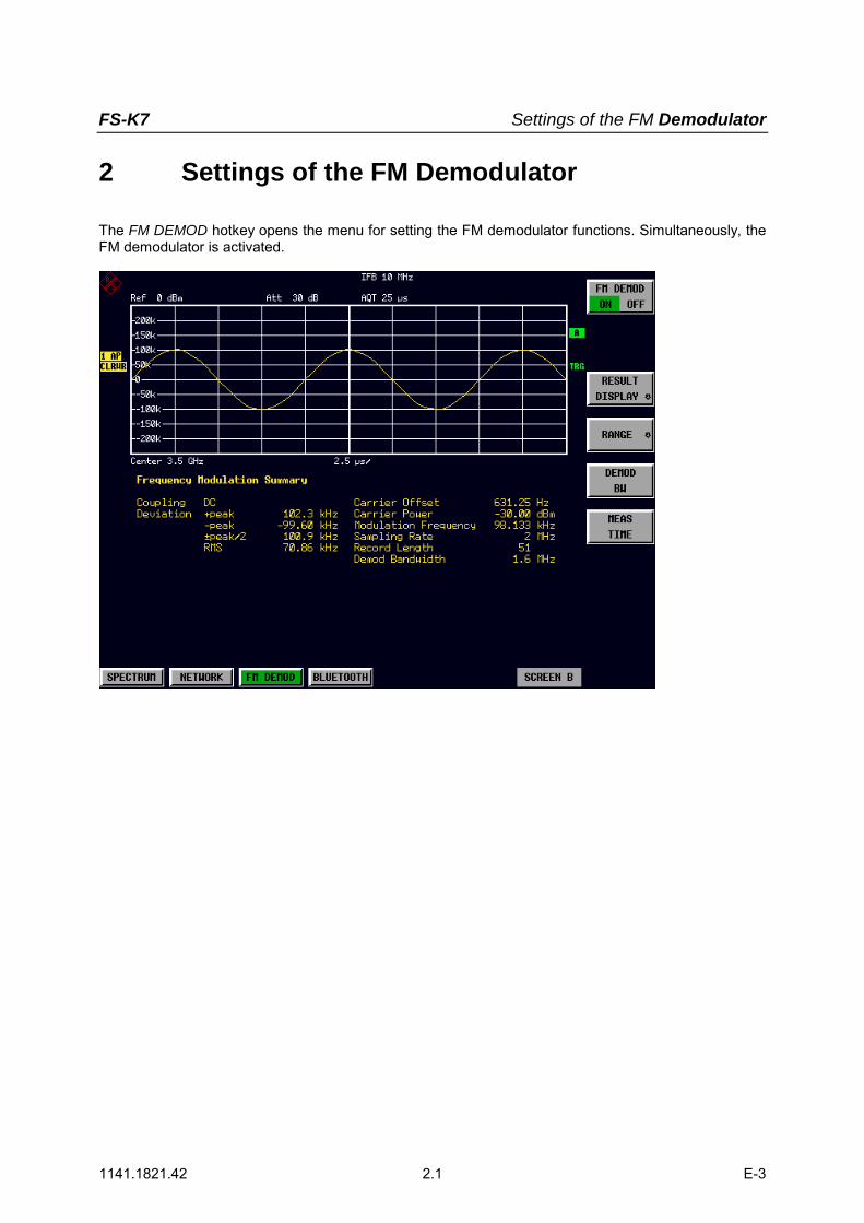
2 Settings of the FM Demodulator
The FM DEMOD hotkey opens the menu for setting the FM demodulator functions. Simultaneously, theFM demodulator is activated.

FS-K7 MKR Key
1141.1821.42 2.2 E-3
FM Demodulator Main Menu
FM DEMODON OFF
RANGE
DEMODBW
MEASTIME
RESULTDISPLAY
FM DEMODFM
PM
SELECTTRACE
ZOOM
DEVIATIONPER DIV
REFERENCEPOSITION
REFERENCEVALUE
PHASE WRAPON OFF
DEVIATIONLIN LOG
DBPER DIV
RF POWERPER DIV
MAX DISPRF POWER
RANGELINEAR
RANGELOG MANUAL
RANGELINEAR %
RANGELINEAR dB
FMFM AF SpektrumPMPM AF SpektrumAMAM AF Spektrum
RF PowerRF Power AF SpektrumRF Spektrum
RFPOWER
RFSPECTRUM
Result Display:
DIAGRAMFULL SIZE
AM
AFSPECTRUM
ZERO PHASEREF POINT
UNIT
PM UNITRAD DEG
AF COUPAC DC
EINBETTEN
Note: The softkeys visible in the RANGE submenu depend on the selected measurementfunction (FM / PM / RF SPECTRUM / AF SPECTRUM).
FM DEMODON OFF
The FM DEMOD ON / OFF softkey switches the FM demodulator on or off.The FM demodulator default setting is OFF; however, when the FM DEMODmode is selected, the demodulator is switched on automatically.
Notes:
• The resolution bandwidth, video bandwidth and sweep time active before thedemodulator is switched on are restored when the demodulator is switchedoff.
• Similarly, the trace operating mode and detector are restored (the FMdemodulator has separate trace settings).
IEC/IEEE-bus command INST:SEL ADEMINST:NSEL 3
RESULTDISPLAY
The RESULT DISPLAY softkey opens the submenu for selecting themeasurement function required (see chapter "Selection of Display Mode -RESULT DISPLAY Menu").
RANGE The RANGE softkey opens the submenu for setting the display range of themeasurement function selected (see chapter "Scaling of Measurement Results- RANGE Menu").

FS-K7 FM Demodulator Main Menu
1141.1821.42 2.3 E-3
DEMODBW
The demodulation bandwidth of the FM demodulator is selected using theDEMOD BW softkey. The demodulation bandwidth determines the samplingrate for recording the signal to be analyzed.The following table shows the relation between demodulation bandwidth andsampling rate:
Demodulationbandwidth
Sampling rate Comment
120 MHz 256 MHz with FSQ-B72only
50/85 MHz (1) 128 MHz with FSQ-B72only
30 MHz 64 MHz with FSQ only
18 MHz 32 MHz with FSQ only
10 MHz 32 MHz
8 MHz 16 MHz
5 MHz 8 MHz
3 MHz 4 MHz
1.6 MHz 2 MHz
800 kHz 1 MHz
400 kHz 500 kHz
200 kHz 250 kHz
100 kHz 125 kHz
50 kHz 62.5 kHz
25 kHz 31.25 kHz
12.5 kHz 15.625 kHz
6.4 kHz 7.8125 kHz
3.2 kHz 3.90625 kHz
1.6 kHz 1.953125 kHz
800 Hz 976.5625 Hz
400 Hz 488.28125 Hz
200 Hz 244.140625 Hz
100 Hz 122.0703125 Hz
(1) The demodulation bandwidth at a sampling rate of 128 MHz depends on the center frequency that has been set.At a center frequency of ≤3.6 GHz, the demodulation bandwidth is 50 MHz; at higher center frequencies, it is 85 MHz.
IEC/IEEE-bus command SENS:BAND:DEM 10MHz
FS-K7 MKR Key
1141.1821.42 2.4 E-3
MEASTIME
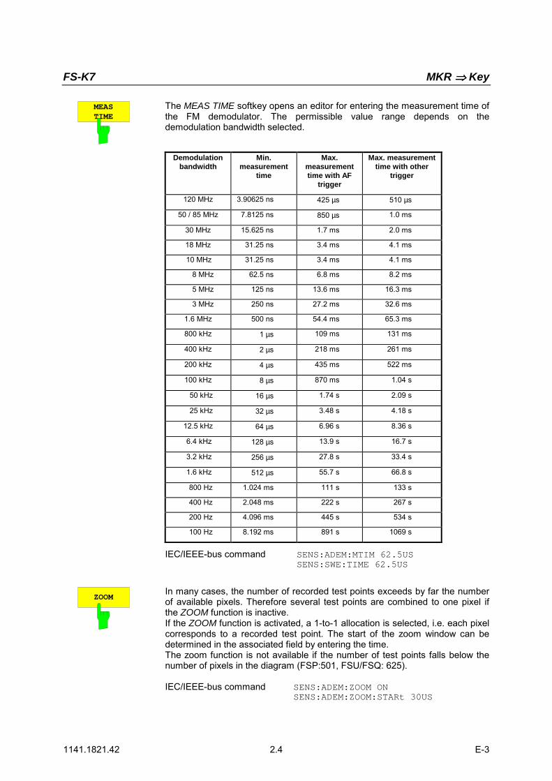
The MEAS TIME softkey opens an editor for entering the measurement time ofthe FM demodulator. The permissible value range depends on thedemodulation bandwidth selected.
Demodulationbandwidth
Min.measurement
time
Max.measurementtime with AF
trigger
Max. measurementtime with other
trigger
120 MHz 3.90625 ns 425 µs 510 µs
50 / 85 MHz 7.8125 ns 850 µs 1.0 ms
30 MHz 15.625 ns 1.7 ms 2.0 ms
18 MHz 31.25 ns 3.4 ms 4.1 ms
10 MHz 31.25 ns 3.4 ms 4.1 ms
8 MHz 62.5 ns 6.8 ms 8.2 ms
5 MHz 125 ns 13.6 ms 16.3 ms
3 MHz 250 ns 27.2 ms 32.6 ms
1.6 MHz 500 ns 54.4 ms 65.3 ms
800 kHz 1 µs 109 ms 131 ms
400 kHz 2 µs 218 ms 261 ms
200 kHz 4 µs 435 ms 522 ms
100 kHz 8 µs 870 ms 1.04 s
50 kHz 16 µs 1.74 s 2.09 s
25 kHz 32 µs 3.48 s 4.18 s
12.5 kHz 64 µs 6.96 s 8.36 s
6.4 kHz 128 µs 13.9 s 16.7 s
3.2 kHz 256 µs 27.8 s 33.4 s
1.6 kHz 512 µs 55.7 s 66.8 s
800 Hz 1.024 ms 111 s 133 s
400 Hz 2.048 ms 222 s 267 s
200 Hz 4.096 ms 445 s 534 s
100 Hz 8.192 ms 891 s 1069 s
IEC/IEEE-bus command SENS:ADEM:MTIM 62.5USSENS:SWE:TIME 62.5US
ZOOMIn many cases, the number of recorded test points exceeds by far the numberof available pixels. Therefore several test points are combined to one pixel ifthe ZOOM function is inactive.If the ZOOM function is activated, a 1-to-1 allocation is selected, i.e. each pixelcorresponds to a recorded test point. The start of the zoom window can bedetermined in the associated field by entering the time.The zoom function is not available if the number of test points falls below thenumber of pixels in the diagram (FSP:501, FSU/FSQ: 625).
IEC/IEEE-bus command SENS:ADEM:ZOOM ONSENS:ADEM:ZOOM:STARt 30US

FS-K7 FM Demodulator Main Menu
1141.1821.42 2.5 E-3
Selection of Display Mode – RESULT DISPLAY MenuIn order to display the measurement results the screen is divided in two halves:In the upper half, the measurement results are displayed as a trace, in the lower half the results ofadditional evaluation functions are shown. The RESULT DISPLAY softkey allows the user to select themeasurement results to be displayed.
RESULTDISPLAY
FM
PM
SELECTTRACE
DIAGRAMFULL SIZE
RFSPECTRUM
RFPOWER
AM
AFSPECTRUM
The RESULT DISPLAY softkey opens a submenu forselecting the measurement result to be displayed.
The demodulated FM, PM or AM signal, the RF signal in thetime domain or the RF or AF frequency spectrum determined viaFFT can be selected for display.
All displays are determined from the I/Q data set recorded forthe measurement. In SINGLE SWEEP mode, the single dataset recorded can be evaluated in all displays simply byswitching the result display.

FS-K7 MKR Key
1141.1821.42 2.6 E-3
FM The FM softkey selects the demodulated FM signal for display. Depending on theAF COUPLING AC/DC selection in the RANGE menu, the average value of thedemodulated signal is mapped onto the vertical center of the diagram (ACselected) or deviates from the center of the diagram by a signal-dependentfrequency offset (DC selected).
In SINGLE SWEEP mode, the data is determined from the current I/Q data set,i.e. a change to FM does not trigger a new measurement.
IEC/IEEE-bus command CALC:FEED 'XTIM:FM'
EINBETTEN
FS-K7 FM Demodulator Main Menu
1141.1821.42 2.7 E-3
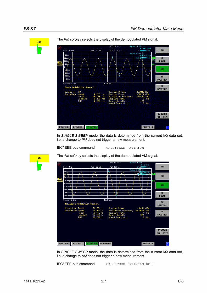
PMThe PM softkey selects the display of the demodulated PM signal.
In SINGLE SWEEP mode, the data is determined from the current I/Q data set,i.e. a change to PM does not trigger a new measurement.
IEC/IEEE-bus command CALC:FEED 'XTIM:PM'
AMThe AM softkey selects the display of the demodulated AM signal.
In SINGLE SWEEP mode, the data is determined from the current I/Q data set,i.e. a change to AM does not trigger a new measurement.
IEC/IEEE-bus command CALC:FEED 'XTIM:AM:REL'

FS-K7 MKR Key
1141.1821.42 2.8 E-3
RF POWER The RF POWER softkey selects the display of the RF signal in the time domain.In contrast to normal analyzer operation, the level values are determined from therecorded I/Q data set by means of summation.
In SINGLE SWEEP mode, the data is determined from the current I/Q data set,i.e. a change to RF POWER does not trigger a new measurement.
IEC/IEEE-bus command CALC:FEED 'XTIM:RFP'
FS-K7 FM Demodulator Main Menu
1141.1821.42 2.9 E-3
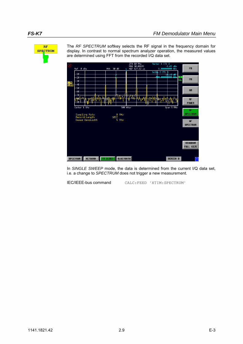
RFSPECTRUM
The RF SPECTRUM softkey selects the RF signal in the frequency domain fordisplay. In contrast to normal spectrum analyzer operation, the measured valuesare determined using FFT from the recorded I/Q data set.
In SINGLE SWEEP mode, the data is determined from the current I/Q data set,i.e. a change to SPECTRUM does not trigger a new measurement.
IEC/IEEE-bus command CALC:FEED 'XTIM:SPECTRUM'

FS-K7 MKR Key
1141.1821.42 2.10 E-3
AFSPECTRUM
The AF SPECTRUM softkey selects the display of the AF spectrum. The AFspectrum can be calculated from the FM signal, PM signal or the RF signal in thetime domain.The softkey is not available if the RF spectrum display is selected.
In SINGLE SWEEP mode, the data is determined from the current I/Q data set,i.e. a change to AF SPECTRUM does not trigger a new measurement.
IEC/IEEE-bus command CALC:FEED 'XTIM:FM:AFSP'CALC:FEED 'XTIM:PM:AFSP'CALC:FEED 'XTIM:AM:AFSP'
CALC:FEED 'XTIM:RFP:AFSP'
SELECTTRACE
The SELECT TRACE softkey selects the trace, the data of which is to bedisplayed in the lower half of the screen.
IEC/IEEE-bus command --
FULL SIZEDIAGRAM
The FULL SIZE DIAGRAM switches the diagram to full screen size.
IEC/IEEE-bus command: DISP:SIZE LARG
FS-K7 FM Demodulator Main Menu
1141.1821.42 2.11 E-3
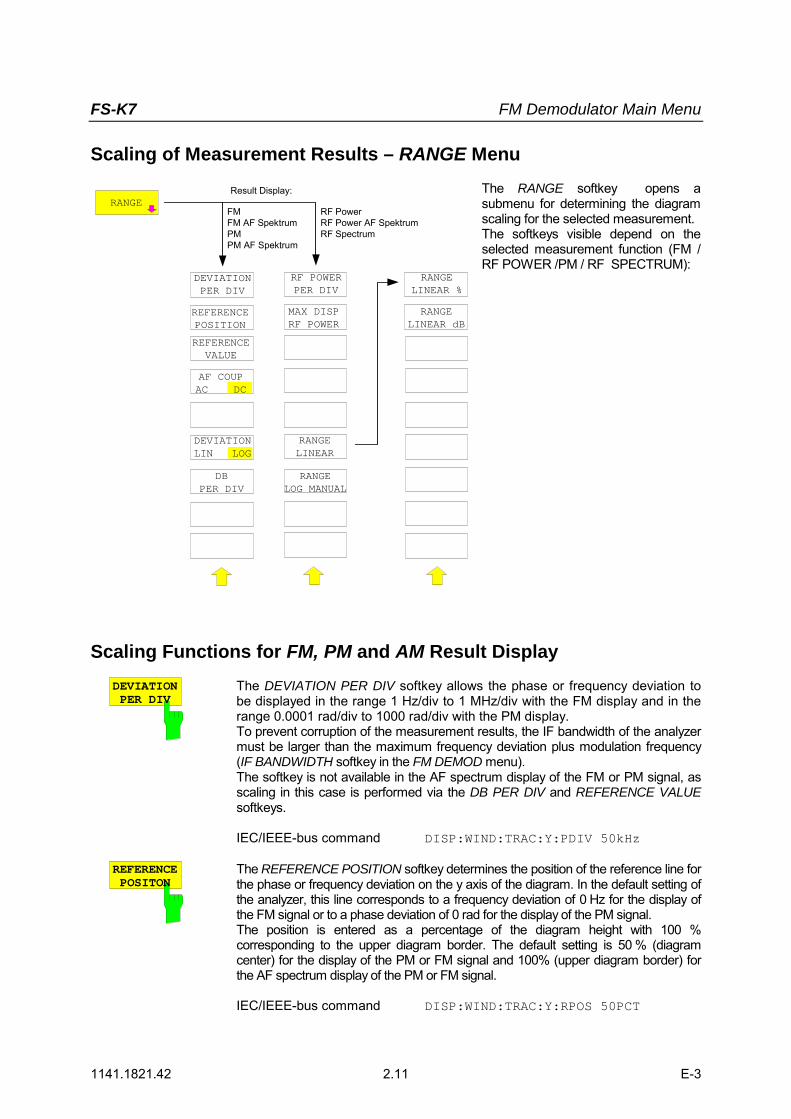
Scaling of Measurement Results – RANGE Menu
RANGE
DEVIATIONPER DIV
REFERENCEPOSITION
REFERENCEVALUE
AF COUPAC DC
DEVIATIONLIN LOG
DBPER DIV
RF POWERPER DIV
MAX DISPRF POWER
RANGELINEAR
RANGELOG MANUAL
RANGELINEAR %
RANGELINEAR dB
FMFM AF SpektrumPMPM AF Spektrum
RF PowerRF Power AF SpektrumRF Spectrum
Result Display: The RANGE softkey opens asubmenu for determining the diagramscaling for the selected measurement.The softkeys visible depend on theselected measurement function (FM /RF POWER /PM / RF SPECTRUM):
Scaling Functions for FM, PM and AM Result DisplayDEVIATIONPER DIV
The DEVIATION PER DIV softkey allows the phase or frequency deviation tobe displayed in the range 1 Hz/div to 1 MHz/div with the FM display and in therange 0.0001 rad/div to 1000 rad/div with the PM display.To prevent corruption of the measurement results, the IF bandwidth of the analyzermust be larger than the maximum frequency deviation plus modulation frequency(IF BANDWIDTH softkey in the FM DEMOD menu).The softkey is not available in the AF spectrum display of the FM or PM signal, asscaling in this case is performed via the DB PER DIV and REFERENCE VALUEsoftkeys.
IEC/IEEE-bus command DISP:WIND:TRAC:Y:PDIV 50kHz
REFERENCEPOSITON
The REFERENCE POSITION softkey determines the position of the reference line forthe phase or frequency deviation on the y axis of the diagram. In the default setting ofthe analyzer, this line corresponds to a frequency deviation of 0 Hz for the display ofthe FM signal or to a phase deviation of 0 rad for the display of the PM signal.The position is entered as a percentage of the diagram height with 100 %corresponding to the upper diagram border. The default setting is 50 % (diagramcenter) for the display of the PM or FM signal and 100% (upper diagram border) forthe AF spectrum display of the PM or FM signal.
IEC/IEEE-bus command DISP:WIND:TRAC:Y:RPOS 50PCT

FS-K7 MKR Key
1141.1821.42 2.12 E-3
REFERENCEVALUE
The REFERENCE VALUE softkey determines the frequency or phasedeviation at the reference line of the y axis. The reference value is setseparately for each display of the PM and FM signal and the AF spectrum ofthe PM and FM signal.
FM signal display:The reference value makes it possible to take individual frequency offsets intoaccount in the trace display (in contrast, the AF COUP AC/DC softkey permitsautomatic correction by the average frequency offset of the signal).Values between 0 and ± 10 MHz can be selected. The softkey is not available ifthe AF COUP AC function has been activated.
AF spectrum display of the FM signal:In the default setting, the reference value defines the FM deviation at the upperdiagram border.Values between 0 and 10 MHz can be selected.
PM signal display:The reference value makes it possible to take individual phase offsets intoaccount in the trace display (in contrast, the AF COUP AC/DC softkey permitsautomatic correction by the average phase offset of the signal).Values between 0 and ± 10000 rad can be selected. The softkey is notavailable if the AF COUP AC function has been activated.
AF spectrum display of the PM signal:In the default setting, the reference value defines the PM deviation at the upperdiagram border.Values between 0 and 10000 rad can be selected.
IEC/IEEE-bus command DISP:WIND:TRAC:Y:RVAL 0HZ
AF COUPAC DC
The AF COUP AC/DC softkey controls the automatic correction of thefrequency offset and phase offset of the input signal:
FM signal display: If DC is selected, the absolute frequency is displayed, i.e. an input signal
with an offset relative to the center frequency is not displayedsymmetrically with respect to the zero line.
If AC is selected, the frequency offset is automatically corrected, i.e. thetrace is always symmetric with respect to the zero line.
PM signal display: If DC is selected, the phase runs according to the existing frequency offset.
In addition, the DC signal contains a phase offset of ±π. If AC is selected, the frequency offset and phase offset are automatically
corrected, i.e. the trace is always symmetric with respect to the zero line.
The softkey is not available with the AF spectrum display of the FM or PMsignal.
IEC/IEEE-bus command SENS:ADEM:AF:COUP DC

FS-K7 FM Demodulator Main Menu
1141.1821.42 2.13 E-3
ZERO PHASEREF POS
The ZERO PHASE REF POS softkey defines the position at which the phaseof the PM-demodulated signal is set to 0 rad. The entry is made with respect totime. In the default setting, the first measured value is set to 0 rad.This softkey is available only in the PM display with DC coupling.
IEC/IEEE-bus command SENS:ADEM:PM:RPO:X 10us
DEVIATIONLIN LOG
The DEVIATION LIN/LOG softkey switches between logarithmic and lineardisplay of the frequency deviation or phase deviation or modulation depth (AM).The softkey is only available in the AF spectrum deviation of the FM or PM orAM signal.
IEC/IEEE-bus command DISP:WIND:TRAC:Y:SPAC LOG
DBPER DIV
The DB PER DIV softkey makes it possible to select the FM or PM deviation ormodulation depth to be displayed in the range 0.1 dB/div to 20 dB/div.The softkey is not available if linear display is set.
IEC/IEEE-bus command DISP:WIND:TRAC:Y:PDIV 5DB
PHASE WRAPON OFF
The PHASE WRAP ON/OFF softkey activates/deactivates phase wrap.
ON The phase will be displayed in the range ±180° (±π). For example, if thephase exceeds +180°, 360° is subtracted from the phase value, with thedisplay thus showing >-180°.
OFF The phase will not be wrapped.
This softkey in available in the PM signal displays.
IEC/IEEE-bus command CALC:FORM PHAS
UNITThe UNIT softkey opens the submenu for selecting units.
PM UNITRAD DEG
The PM UNIT RAD/DEG softkey is used to select the unit for displaying PMsignals.
IEC/IEEE-bus command UNIT:ANGL RAD
FS-K7 MKR Key
1141.1821.42 2.14 E-3
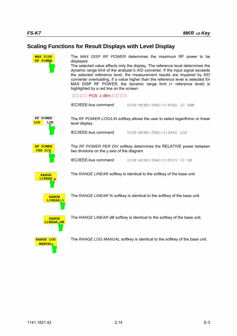
Scaling Functions for Result Displays with Level DisplayMAX DISPRF POWER
The MAX DISP RF POWER determines the maximum RF power to bedisplayed.The selected value affects only the display. The reference level determines thedynamic range limit of the analyzers A/D converter. If the input signal exceedsthe selected reference level, the measurement results are impaired by A/Dconverter overloading. If a value higher than the reference level is selected forMAX DISP RF POWER, the dynamic range limit (= reference level) ishighlighted by a red line on the screen:
POS x dBm
IEC/IEEE-bus command DISP:WIND:TRAC:Y:RVAL 10 DBM
RF POWERLOG LIN
The RF POWER LOG/LIN softkey allows the user to select logarithmic or linearlevel display.
IEC/IEEE-bus command DISP:WIND:TRAC:Y:SPAC LOG
RF POWERPER DIV
The RF POWER PER DIV softkey determines the RELATIVE power betweentwo divisions on the y axis of the diagram.
IEC/IEEE-bus command DISP:WIND:TRAC:Y:PDIV 10 DB
RANGELINEAR
The RANGE LINEAR softkey is identical to the softkey of the base unit.
RANGELINEAR %
The RANGE LINEAR % softkey is identical to the softkey of the base unit.
RANGELINEAR dB
The RANGE LINEAR dB softkey is identical to the softkey of the base unit.
RANGE LOGMANUAL
The RANGE LOG MANUAL softkey is identical to the softkey of the base unit.

FS-K7 FREQ Key
1141.1821.42 2.15 E-3
FREQ Key
Span <> 0 Span = 0
FREQ CENTER
CF-STEPSIZE
0.1 * SPAN
0.5 * SPAN
x * SPAN
= CENTER
0.1 * RBW
0.5 * RBW
x * RBW
= CENTER
MANUAL MANUAL
AFCENTER
AF START
AF STOP
The FREQ menu functions areidentical to those of the base unit.
If the AF spectrum display is active,the AF CENTER, AF START andAF STOP softkeys, with which thedisplayed frequency range is definedwithin the demodulation bandwidth,are also available.
AF CENTERThe AF CENTER softkey allows the user to select the center frequencywithin the AF spectrum.
IEC/IEEE-bus command SENS:ADEM:AF:CENT 1MHZ
AF STARTThe AF START softkey allows the user to select the start frequency withinthe AF spectrum.
IEC/IEEE-bus command SENS:ADEM:AF:STAR 0HZ
AF STOPThe AF STOP softkey allows the user to select the stop frequency within theAF spectrum.The maximum AF stop frequency corresponds to half the demodulationbandwidth.
IEC/IEEE-bus command SENS:ADEM:AF:STOP 2MHZ

FS-K7 MKR Key
1141.1821.42 2.16 E-3
SPAN Key
DEMODBW
AFFULL SPAN
AF SPAN
SPANAF Spectrum RF Spectrum
Result Display:
DEMODBW
FULL SPAN
FREQUENCYSPAN
The SPAN menu allows the user to select thefrequency range to be displayed if the spectrumdisplays of the FM demodulator are active.
AF SPANThe AF SPAN softkey allows the user to select the frequencyrange if the AF spectrum displays are active.Values between the sampling rate/200 and the demodulationbandwidth/2 can be selected.
IEC/IEEE-bus command ADEM:AF:SPAN 2.5 MHz
FREQUENCYSPAN
The FREQUENCY SPAN softkey allows the user to select thefrequency range if the RF SPECTRUM display is active.Values between the sampling rate/200 and the demodulationbandwidth/2 can be selected.
IEC/IEEE-bus command ADEM:SPEC:SPAN:ZOOM 5 MHz
AFFULL SPAN
The AF FULL SPAN softkey sets the maximum frequency range ifthe AF spectrum displays are active.The maximum frequency range corresponds to half thedemodulation bandwidth.
IEC/IEEE-bus command ADEM:AF:SPAN:FULL
FS-K7 SPAN Key
1141.1821.42 2.17 E-3
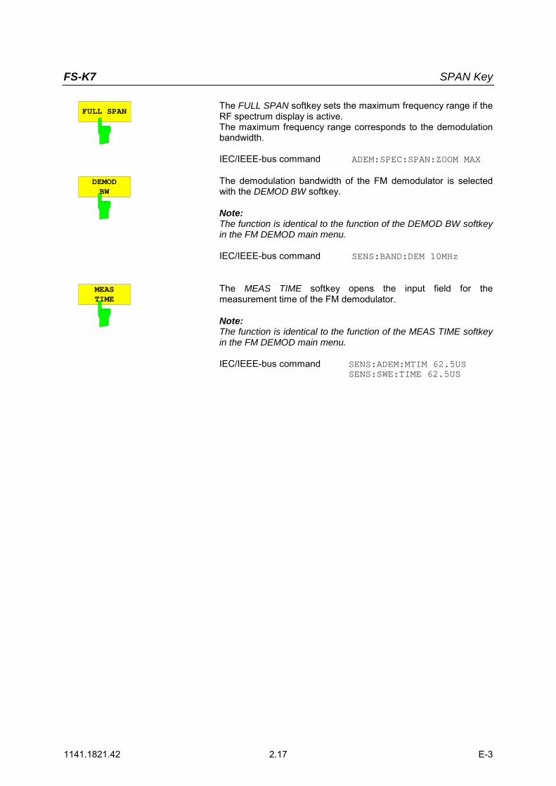
FULL SPANThe FULL SPAN softkey sets the maximum frequency range if theRF spectrum display is active.The maximum frequency range corresponds to the demodulationbandwidth.
IEC/IEEE-bus command ADEM:SPEC:SPAN:ZOOM MAX
DEMODBW
The demodulation bandwidth of the FM demodulator is selectedwith the DEMOD BW softkey.
Note:The function is identical to the function of the DEMOD BW softkeyin the FM DEMOD main menu.
IEC/IEEE-bus command SENS:BAND:DEM 10MHz
MEASTIME
The MEAS TIME softkey opens the input field for themeasurement time of the FM demodulator.
Note:The function is identical to the function of the MEAS TIME softkeyin the FM DEMOD main menu.
IEC/IEEE-bus command SENS:ADEM:MTIM 62.5USSENS:SWE:TIME 62.5US

FS-K7 MKR Key
1141.1821.42 2.18 E-3
AMPT Key
REF LEVEL
RF ATTENAUTO
RANGELOG 100 dB
RANGELINEAR
RANGELOG MANUAL
REF LEVELPOSITION
REF LEVELOFFSET
RF ATTENMANUAL
RF INPUT50Ω 75Ω
EL ATTENAUTO
EL ATTENMANUAL
EL ATTENOFF
OptionFSP-B25
OptionFSP-B25
OptionFSP-B25
AMPTRANGE
LINEAR %
RANGELINEAR dB
The AMPT menu functions are identical to those of the base unit.
Die following functions are only available with level displays:
RANGE LOG 100 dBRANGE LOG MANUALRANGE LINEAR
Note:The REF LEVEL value defines the clipping level of the A/D converter and must therefore be set greaterthan or equal to the maximum power of the signal to be analyzed.

FS-K7 BW Key
1141.1821.42 2.19 E-3
BW Key
DEMODBW
MEASTIME
RES BWBW
IF BWAUTO
IF BWMANUAL
The BW menu comprises all functions relating to the bandlimiting of the analyzed signal.
RES BWIf the Spectrum result display is active, the RES BW softkey selects theresolution bandwidth for the signal displayed. Note that these resolutionbandwidths are obtained by means of FFT filters from 1 Hz to 10 MHz.
Notes: The softkey is available only if the RF SPECTRUM or AFSPECTRUM result display is active.The IF bandwidth is limited by analog LC filters using the IF BWMANUAL and IF BW AUTO softkeys.
IEC/IEEE-bus command ADEM:SPEC:BAND:RES 10 kHz
IF BWAUTO
The IF BW AUTO softkey couples the IF bandwidth of the analyzer (i.e. thebandwidth of the analog LC filters) to the selected demodulation bandwidth.
IEC/IEEE-bus command BAND:RES:AUTO ON
IF BWMANUAL
The IF BW MANUAL softkey allows the IF bandwidth of the analyzer to beentered (i.e. the bandwidth of the analog filters). Bandwidths from 300 kHz to10 MHz can be selected.
IEC/IEEE-bus command BAND:RES 1 MHz
Notes: Manual setting of the IF bandwidth is usually not required. If an IFbandwidth is set that is narrower than the value defined by AUTOcoupling,a) the RF frequency response is identical to that of the IF filter if
the spectrum display is active,b) an AF frequency response corresponding to a lowpass filter
equivalent to the IF filter occurs in the case of FMdemodulation.

FS-K7 MKR Key
1141.1821.42 2.20 E-3
DEMODBW
The demodulation bandwidth of the FM demodulator is selected via the DEMODBW softkey.
Note: The function is identical to that of the DEMOD BW softkey in the FMDEMOD main menu.
IEC/IEEE-bus command SENS:BAND:DEM 10MHz
MEASTIME
The MEAS TIME softkey opens the editor for entering the data-recording time ofthe FM demodulator.
Note: The function is identical to that of the MEAS TIME softkey in theFM DEMOD main menu.
IEC/IEEE-bus command SENS:ADEM:MTIM 62.5USSENS:SWE:TIME 62.5US
FS-K7 TRIG Key
1141.1821.42 2.21 E-3
TRIG Key
TRIGGEROFFSET
FREERUN
TRIGGER
DEMODSIGNAL
EXTERN
POLARITYPOS NEG
IF POWER
FMSIGNAL
PMSIGNAL
AMSIGNAL
RF POWERSIGNAL
RF POWEROption FSP-B6
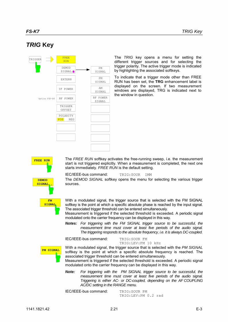
The TRIG key opens a menu for setting thedifferent trigger sources and for selecting thetrigger polarity. The active trigger mode is indicatedby highlighting the associated softkeys.
To indicate that a trigger mode other than FREERUN has been set, the TRG enhancement label isdisplayed on the screen. If two measurementwindows are displayed, TRG is indicated next tothe window in question.
FREE RUN The FREE RUN softkey activates the free-running sweep, i.e. the measurementstart is not triggered explicitly. When a measurement is completed, the next onestarts immediately. FREE RUN is the default setting.
IEC/IEEE-bus command: TRIG:SOUR IMM
DEMODSIGNAL
The DEMOD SIGNAL softkey opens the menu for selecting the various triggersources.
FMSIGNAL
With a modulated signal, the trigger source that is selected with the FM SIGNALsoftkey is the point at which a specific absolute phase is reached by the input signal.The associated trigger threshold can be entered simultaneously.Measurement is triggered if the selected threshold is exceeded. A periodic signalmodulated onto the carrier frequency can be displayed in this way.Notes: For triggering with the FM SIGNAL trigger source to be successful, the
measurement time must cover at least five periods of the audio signal.The triggering responds to the absolute frequency, i.e. it is always DC-coupled.
IEC/IEEE-bus command: TRIG:SOUR FMTRIG:LEV:FM 10 kHz
PM SIGNALWith a modulated signal, the trigger source that is selected with the PM SIGNALsoftkey is the point at which a specific absolute frequency is reached. Theassociated trigger threshold can be entered simultaneously.Measurement is triggered if the selected threshold is exceeded. A periodic signalmodulated onto the carrier frequency can be displayed in this way.
Note: For triggering with the PM SIGNAL trigger source to be successful, themeasurement time must cover at least five periods of the audio signal.Triggering is either AC- or DC-coupled, depending on the AF COUPLINGAC/DC setting in the RANGE menu.
IEC/IEEE-bus command: TRIG:SOUR PMTRIG:LEV:PM 0.2 rad
FS-K7 MKR Key
1141.1821.42 2.22 E-3
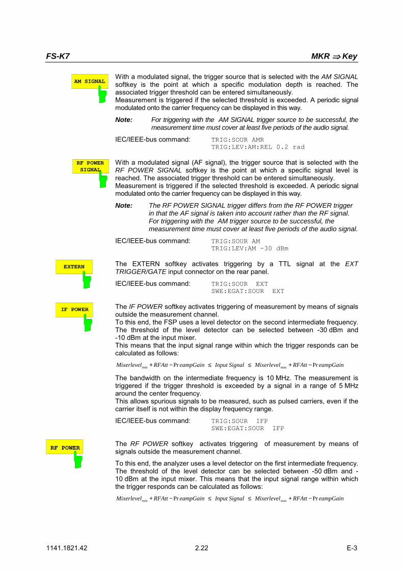
AM SIGNALWith a modulated signal, the trigger source that is selected with the AM SIGNALsoftkey is the point at which a specific modulation depth is reached. Theassociated trigger threshold can be entered simultaneously.Measurement is triggered if the selected threshold is exceeded. A periodic signalmodulated onto the carrier frequency can be displayed in this way.
Note: For triggering with the AM SIGNAL trigger source to be successful, themeasurement time must cover at least five periods of the audio signal.
IEC/IEEE-bus command: TRIG:SOUR AMRTRIG:LEV:AM:REL 0.2 rad
RF POWERSIGNAL
With a modulated signal (AF signal), the trigger source that is selected with theRF POWER SIGNAL softkey is the point at which a specific signal level isreached. The associated trigger threshold can be entered simultaneously.Measurement is triggered if the selected threshold is exceeded. A periodic signalmodulated onto the carrier frequency can be displayed in this way.
Note: The RF POWER SIGNAL trigger differs from the RF POWER triggerin that the AF signal is taken into account rather than the RF signal.For triggering with the AM trigger source to be successful, themeasurement time must cover at least five periods of the audio signal.
IEC/IEEE-bus command: TRIG:SOUR AMTRIG:LEV:AM –30 dBm
EXTERN The EXTERN softkey activates triggering by a TTL signal at the EXTTRIGGER/GATE input connector on the rear panel.
IEC/IEEE-bus command: TRIG:SOUR EXTSWE:EGAT:SOUR EXT
IF POWER The IF POWER softkey activates triggering of measurement by means of signalsoutside the measurement channel.To this end, the FSP uses a level detector on the second intermediate frequency.The threshold of the level detector can be selected between -30 dBm and-10 dBm at the input mixer.This means that the input signal range within which the trigger responds can becalculated as follows:
eampGainRFAttMixerlevelSignalInputeampGainRFAttMixerlevel PrPr maxmin −+≤≤−+
The bandwidth on the intermediate frequency is 10 MHz. The measurement istriggered if the trigger threshold is exceeded by a signal in a range of 5 MHzaround the center frequency.This allows spurious signals to be measured, such as pulsed carriers, even if thecarrier itself is not within the display frequency range.
IEC/IEEE-bus command: TRIG:SOUR IFPSWE:EGAT:SOUR IFP
RF POWERThe RF POWER softkey activates triggering of measurement by means ofsignals outside the measurement channel.
To this end, the analyzer uses a level detector on the first intermediate frequency.The threshold of the level detector can be selected between -50 dBm and -10 dBm at the input mixer. This means that the input signal range within whichthe trigger responds can be calculated as follows:
eampGainRFAttMixerlevelSignalInputeampGainRFAttMixerlevel PrPr maxmin −+≤≤−+
FS-K7 TRIG Key
1141.1821.42 2.23 E-3
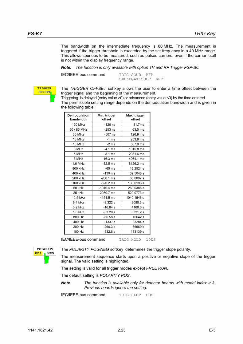
The bandwidth on the intermediate frequency is 80 MHz. The measurement istriggered if the trigger threshold is exceeded by the set frequency in a 40 MHz range.This allows spurious to be measured, such as pulsed carriers, even if the carrier itselfis not within the display frequency range.
Note: The function is only available with option TV and RF Trigger FSP-B6.
IEC/IEEE-bus command: TRIG:SOUR RFPSWE:EGAT:SOUR RFP
TRIGGEROFFSET
The TRIGGER OFFSET softkey allows the user to enter a time offset between thetrigger signal and the beginning of the measurement.Triggering is delayed (entry value >0) or advanced (entry value <0) by the time entered.The permissible setting range depends on the demodulation bandwidth and is given inthe following table:
Demodulationbandwidth
Min. triggeroffset
Max. triggeroffset
120 MHz -126 ns 31.7ms50 / 85 MHz -253 ns 63.5 ms
30 MHz -507 ns 126.9 ms18 MHz -1 ms 253.9 ms10 MHz -2 ms 507.9 ms8 MHz -4.1 ms 1015.8 ms5 MHz -8.1 ms 2031.6 ms3 MHz -16.3 ms 4064.1 ms
1.6 MHz -32.5 ms 8126.2 ms800 kHz -65 ms 16.2524 s400 kHz -130 ms 32.5048 s200 kHz -260.1 ms 65.0097 s100 kHz -520.2 ms 130.0193 s50 kHz -1040.4 ms 260.0386 s25 kHz -2080.7 ms 520.0773 s
12.5 kHz -4151.5 ms 1040.1546 s6.4 kHz -8.322 s 2080.3 s3.2 kHz -16.64 s 4160.6 s1:6 kHz -33.29 s 8321.2 s800 Hz -66.58 s 16642 s400 Hz -133.1s 33284 s200 Hz -266.3 s 66569 s100 Hz -532.6 s 133139 s
IEC/IEEE-bus command TRIG:HOLD 10US
POLARITYPOS NEG
The POLARITY POS/NEG softkey determines the trigger slope polarity.
The measurement sequence starts upon a positive or negative slope of the triggersignal. The valid setting is highlighted.
The setting is valid for all trigger modes except FREE RUN.
The default setting is POLARITY POS.
Note: The function is available only for detector boards with model index ≥ 3.Previous boards ignore the setting.
IEC/IEEE-bus command: TRIG:SLOP POS

FS-K7 MKR Key
1141.1821.42 2.24 E-3
MKR Key
ALL MARKEROFF
MARKER 4
MARKERNORM DELTA
MARKER 3
MARKER 2
MARKER 1MKRThe MKR menu functions are identical to those ofthe base unit.
Only the measurement result display is coupled tothe active result display and is in Hz if FM and FMAF spectrum are selected, in rad if PM and PM AFspectrum are selected, or in dBm or dB if RFPOWER, RF POWER AF spectrum and RFSPECTRUM are selected.
FS-K7 MKR Key
1141.1821.42 2.25 E-3
MKR Key
NEXT PEAK
REF LEVEL=MKR LVL
PEAKEXCURSION
MKR MKR
SELECTMARKER
CENTER=MKR FREQ
SEARCHLIMITS
MRK->TRACE
AMPLSPAN
PEAK MIN
NEXTMIN RIGHT
FCTN
RIGHTLIMIT
LEFTLIMIT
THRESHOLD
SEARCH LIMOFF
NEXTPEAK LEFT
NEXTPEAK RIGHT
NEXTMIN LEFT
NEXT MIN
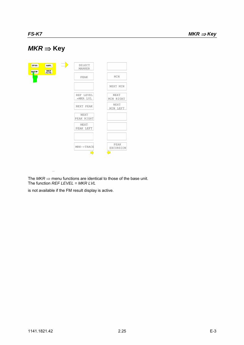
The MKR menu functions are identical to those of the base unit.The function REF LEVEL = MKR LVL
is not available if the FM result display is active.
FS-K7 MKR FCTN Key
1141.1821.42 2.26 E-3
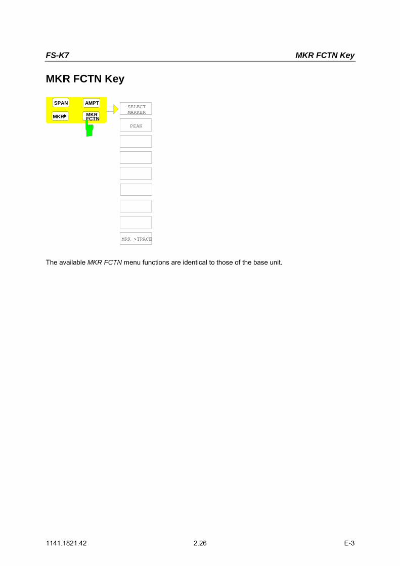
MKR FCTN Key
MKR MKRSELECTMARKER
SHAPE FACT60:3 60:6
MRK->TRACE
AMPTSPAN
PEAK
FCTN
The available MKR FCTN menu functions are identical to those of the base unit.
FS-K7 MEAS Key / Other Keys
1141.1821.12 2.27 E-1
MEAS Key
The MEAS menu functions are not available in the FM DEMOD mode.
Other Keys
The functions of the other keys are identical to those of the base unit. Please refer to the relevantchapters in the operating manual of the base unit.

FS-K7 Contents
1141.1821.42 I-3.1 E-3
Contents - Chapter" Remote Control - Description of Commands "
3 Remote Control - Description of Commands.................................................... 3.1Common Commands....................................................................................................................... 3.1
CALCulate:DELTamarker Subsystem........................................................................................ 3.2CALCulate:FEED Subsystem..................................................................................................... 3.3CALCulate:FORMat - Subsystem .............................................................................................. 3.4CALCulate:MARKer Subsystem................................................................................................. 3.5CALCulate:MARKer:FUNCtion:ADEMod Subsystem ................................................................ 3.6CALCulate:UNIT Subsystem...................................................................................................... 3.9
DISPlay Subsystem........................................................................................................................ 3.10
INSTrument Subsystem ................................................................................................................ 3.12
SENSe Subsystem ......................................................................................................................... 3.13[SENSe:]ADEMod Subsystem ................................................................................................. 3.13[SENSe:]ADEMod:AM Subsystem ........................................................................................... 3.20[SENSe:]ADEMod:FM Subsystem ........................................................................................... 3.29[SENSe:]ADEMod:PM Subsystem ........................................................................................... 3.34[SENSe:]ADEMod:SPECtrum - Subsystem ............................................................................. 3.38SENSe:BANDwidth Subsystem ............................................................................................... 3.42
TRACe Subsystem......................................................................................................................... 3.44
TRIGger Subsystem....................................................................................................................... 3.46UNIT Subsystem ...................................................................................................................... 3.49
Table of Softkeys and Hotkeys including Assignment of Remote-Control Commands ......................... 3.50FM Demodulator Main Menu.................................................................................................... 3.50FREQ Key ................................................................................................................................ 3.51SPAN Key................................................................................................................................. 3.52AMPT Key ................................................................................................................................ 3.52BW Key .................................................................................................................................... 3.53TRIG Key.................................................................................................................................. 3.54MKR Key .................................................................................................................................. 3.54MKR Key.............................................................................................................................. 3.54MKR FCTN Key........................................................................................................................ 3.55


FS-K7 Description of Commands
1141.1821.42 3.1 E-3
3 Remote Control - Description of Commands
The information in this chapter supplements and updates chapters 5 and 6 of the FSP manual. Thischapter contains the new commands that apply specifically to option FS-K7 as well as the modifiedcommands of the basic instrument provided they are used by FS-K7.
Every attempt was made to ensure the highest possible compatibility of the FS-K7 commands withthose of analog demodulation of the FSE family. A few commands were included in the command setfor this reason only.
In the description of menu operation in chapter 2, each softkey is indicated with the associatedIEC/IEEE bus commands.
Note: The measurements of the FM Demodulator mode are always carried out in screen A.Therefore, the commands where the numeric suffix selects the screen must either start withnumeric suffix 1 (i.e. CALCulate1) or without a numeric suffix (i.e. CALCulate).
Common Commands
COMMAND PARAMETERS UNIT COMMENT
*OPT? Option Identification Query;query only
*OPT?OPTION IDENTIFICATION QUERY queries the options included in the instrument and returns a listof the installed options. The options are separated by commas. In the response string, theidentification of option FS-K7 is indicated at position 32:
Example:0,0,0,0,0,0,0,0,0,0,0,0,0,0,0,0,0,0,0,0,0,0,0,0,0,0,0,0,0,0,0,K7,0,0,0,0,0,0,0,0
Description of Commands FS-K7
1141.1821.42 3.2 E-3
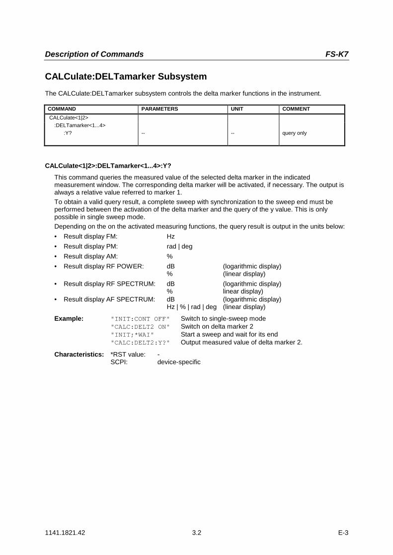
CALCulate:DELTamarker SubsystemThe CALCulate:DELTamarker subsystem controls the delta marker functions in the instrument.
COMMAND PARAMETERS UNIT COMMENT CALCulate<1|2> :DELTamarker<1...4>
:Y? -- -- query only
CALCulate<1|2>:DELTamarker<1...4>:Y?This command queries the measured value of the selected delta marker in the indicatedmeasurement window. The corresponding delta marker will be activated, if necessary. The output isalways a relative value referred to marker 1.To obtain a valid query result, a complete sweep with synchronization to the sweep end must beperformed between the activation of the delta marker and the query of the y value. This is onlypossible in single sweep mode.Depending on the on the activated measuring functions, the query result is output in the units below:• Result display FM: Hz• Result display PM: rad | deg• Result display AM: %• Result display RF POWER: dB (logarithmic display)
% (linear display)• Result display RF SPECTRUM: dB (logarithmic display)
% linear display)• Result display AF SPECTRUM: dB (logarithmic display)
Hz | % | rad | deg (linear display)
Example: "INIT:CONT OFF" Switch to single-sweep mode"CALC:DELT2 ON" Switch on delta marker 2"INIT;*WAI" Start a sweep and wait for its end"CALC:DELT2:Y?" Output measured value of delta marker 2.
Characteristics: *RST value: -SCPI: device-specific

FS-K7 Description of Commands
1141.1821.42 3.3 E-3
CALCulate:FEED SubsystemThe CALCulate:FEED subsystem selects the type of evaluation of the measured data. This correspondsto the selection of the Result Display in manual mode.If the FM demodulator is active, the selection of the type of evaluation is independent of themeasurement window. Therefore, the numeric suffix <1|2> is irrelevant and ignored.
COMMAND PARAMETERS UNIT COMMENT CALCulate<1|2>
:FEED <string> no query
CALCulate<1|2>:FEED <string>
This command selects the trace data to be displayed.
Parameters:<string>::=
'XTIM:AM:RELative[:TDOMain]' Demodulated AM signal in standardized display.
'XTIM:AM:RELative:AFSPectrum<1...3>' AF spectrum of the demodulated AM signal instandardized display, results referenced to traces1 to 3.
'XTIM:AM[:ABSolute][:TDOMain]' Demodulated AM signal in level display.Same as 'XTIM:RFPower'.
'XTIM:AM[:ABSolute]:AFSPectrum<1...3>' AF spectrum of the demodulated AM signal in leveldisplay, results referenced to traces 1 to 3.Same as 'XTIM:RFPower:AFSPectrum'.
'XTIM:RFPower[:TDOMain]' Demodulated AM signal in level display.
'XTIM:RFPower:AFSPectrum<1...3>' AF spectrum of the demodulated AM signal in leveldisplay, results referenced to traces 1 to 3.
'XTIM:FM[:TDOMain]' Demodulated FM signal.
'XTIM:FM:AFSPectrum<1...3>' AF spectrum of the demodulated FM signal, resultsreferenced to traces 1 to 3.
'XTIM:PM[:TDOMain]' Demodulated PM signal
'XTIM:PM:AFSPectrum<1...3>' AF spectrum of the demodulated PM signal
'XTIM:AMSummary<1...3>[:ABSolute]' AM results in level display, referenced totraces 1 to 3.
'XTIM:AMSummary<1...3>:RELative' AM results in standardized display, referenced totraces 1 to 3.
'XTIM:FMSummary<1...3>' FM results, referenced to traces 1 to 3
'XTIM:PMSummary<1...3>' PM results, referenced to traces 1 to 3.
'XTIM:SPECtrum' RF spectrum of the signal determined from themeasured data via FFT.
Example: "CALC:FEED ‘XTIM:FM’" Select the display of the FM signal
Characteristics: *RST value: XTIM:FM’SCPI: conforming
Description of Commands FS-K7
1141.1821.42 3.4 E-3
CALCulate:FORMat - SubsystemThe CALCulate:FORMat subsystem defines the conversion of measured data.
COMMAND PARAMETERS UNIT COMMENTCALCulate<1|2>
:FORMat PHASe | UPHase
:CALCulate<1|2>:FORMat PHASe | UPHase
This command activates the limitation to ±180°.
Parameter: PHASe: Limitation to ±180°UPHase: Unwrapped
Example: ":CALC:FORM PHAS" activated the limitation to ±180°.
Characteristics:: *RST value: UPASSCPI: conforming
Description of Commands FS-K7
1141.1821.42 3.5 E-3
CALCulate:MARKer SubsystemThe CALCulate:MARKer subsystem controls the marker functions in the instrument.
COMMAND PARAMETERS UNIT COMMENTCALCulate<1|2>
:MARKer<1...4>:Y?:PEXCursion
--<numeric_value>
--DB | DEG | RAD |HZ PCT
query only
CALCulate<1|2>:MARKer<1...4>:Y?This command queries the measured value of the selected marker in the selected measurementwindow. The corresponding marker is activated before or switched to marker mode, if necessary.To obtain a valid query result, a complete sweep with synchronization to the sweep end must beperformed between the activation of the marker and the query of the y value. This is only possible insingle sweep mode.
Example: "INIT:CONT OFF" Switch to single-sweep mode"CALC:MARK2 ON" Switch on marker 2"INIT;*WAI" Start a sweep and waits for its end"CALC:MARK2:Y?" Output the measured value of marker 2.
Characteristics: *RST value: -SCPI: device-specific
CALCulate<1|2>:MARKer<1...4>:PEXCursion <numeric_value>
This command defines the peak excursion, i.e. the spacing below the trace maximum which must beattained before a new maximum is recognized, or the spacing above the trace minimum which mustbe attained before a new minimum is recognized. The set value is valid for all markers and deltamarkers.The unit of the numerical value depends on the active display.
Example: "CALC:MARK:PEXC 10dB" ' SPECTRUM display"CALC:MARK:PEXC 100 Hz" ' FM DEMOD display
Characteristics: *RST value: 50 kHz (for FM displays)0.5 RAD (for PM displays)5 PCT (for standardized AM displays)6 dB (for level displays)
SCPI: device-specific
The numeric suffix <1...4> in MARKer is irrelevant.

Description of Commands FS-K7
1141.1821.42 3.6 E-3
CALCulate:MARKer:FUNCtion:ADEMod SubsystemThe CALCulate:MARKer:FUNCtion:ADEMod subsystem contains the marker functions for the optionFM Demodulator FS-K7.
COMMAND PARAMETERS UNIT COMMENTCALCulate<1|2>
:MARKer:FUNCtion
:ADEMod:AM
[:RESult<1...3>?]:FM
[:RESult<1...3>?]:PM
[:RESult<1...3>?]:AFRequency
[:RESult<1...3>?]:FERRor
[:RESult<1...3>?]:SINad
:RESult<1...3>?:THD
:RESult<1...3>?:CARRier
[:RESult<1...3>?]
PPEak | MPEak | MIDDle | RMS
PPEak | MPEak | MIDDle | RMS
PPEak | MPEak | MIDDle | RMS
Option FM Demodulator
query only
query only
query only
query only
query only
query only
query only
query only
CALCulate<1|2>:MARKer<1...4>:FUNCtion:ADEMod:AM[:RESult<1...3>]? PPEak| MPEak| MIDDle| RMS
This command queries the results of the AM modulation measurement. The numeric suffix(:RESult<1...3>) indicates whether trace 1, 2 or 3 is selected.
PPEak Result of measurement with detector +PKMPEak Result of measurement with detector -PKMIDDle Result of averaging ±PK/2RMS Result of measurement with detector RMS
Example: "ADEM ON" 'Switch on FM demodulator"CALC:FEED 'XTIM:AM:REL:TDOM" 'Switch on AM result display"DISP:TRAC ON" 'Switch on trace"CALC:MARK:FUNC:ADEM:AM? PPE" 'Query the peak value
Characteristics: *RST value: -SCPI: device-specific
CALCulate<1|2>:MARKer<1...4>:FUNCtion:ADEMod:FM[:RESult<1...3>]? PPEak | MPEak | MIDDle | RMS
This command queries the results of FM modulation measurement. The numeric suffix indicateswhether trace 1, 2 or 3 is selected.PPEak Result of measurement with detector +PKMPEak Result of measurement with detector -PKMIDDle Result of averaging ±PK/2RMS Result of measurement with detector RMS
Example: "ADEM ON" 'Switch on FM demodulator"CALC:FEED 'XTIM:AM:REL:TDOM" 'Switch on AM result display"DISP:TRAC ON" 'Switch on trace"CALC:MARK:FUNC:ADEM:AM? PPE" 'Query the peak value
Characteristics: *RST value: -SCPI: device-specific

Description of Commands FS-K7
1141.1821.42 3.7 E-3
CALCulate<1|2>:MARKer<1...4>:FUNCtion:ADEMod:PM[:RESult<1...3>]?PPEak | MPEak | MIDDle | RMS
This command queries the results of the PM modulation measurement of analog demodulation. Thenumeric suffix (:RESult<1...3>) indicates whether trace 1, 2 or 3 is selected.
PPEak Result of measurement with detector +PKMPEak Result of measurement with detector -PKMIDDle Result of averaging ±PK/2RMS Result of measurement with detector RMS
Example: "ADEM ON" 'Switch on FM demodulator"CALC:FEED 'XTIM:PM:TDOM" 'Switch on PM result display"DISP:TRAC ON" 'Switch on trace"CALC:MARK:FUNC:ADEM:PM? PPE" 'Query the peak value
Characteristics: *RST value: -SCPI: device-specific
CALCulate<1|2>:MARKer<1...4>:FUNCtion:ADEMod:AFRequency[:RESult<1...3>]?This command queries the audio frequency with analog demodulation. The numeric suffix indicateswhether trace 1, 2 or 3 is selected.Note: If several demodulation modes are activated simultaneously with command
SENS:ADEM:FM:TYPE, SENS:ADEM:PM:TYPE, SENS:ADEM:AM:TYPE,SENS:ADEM:RFP:TYPE, SENS:ADEM:FM:AFSP:TYPE, SENS:ADEM:PM:AFSP:TYPE,SENS:ADEM:AM:AFSP:TYPE or SENS:ADEM:RFP:AFSP, the audio frequency of thedisplay mode selected with CALC:FEED is returned.
Example: "ADEM ON" 'Switch on FM demodulator"CALC:FEED 'XTIM:AM:TDOM" 'Switch on AM result display
or"CALC:FEED 'XTIM:FM:TDOM" 'Switch on FM result display
or"CALC:FEED 'XTIM:FM:AFSP" 'Switch on AF spectrum result"DISP:TRAC ON" 'display of the FM and trace
or"CALC:FEED 'XTIM:RFP:AFSP" 'Switch on AF spectrum result display"DISP:TRAC ON" ' of the RF power signal and trace"CALC:MARK:FUNC:ADEM:AFR? " 'Query audio frequency
Characteristics: *RST value: -SCPI: device-specific
CALCulate<1|2>:MARKer<1...4>:FUNCtion:ADEMod:FERRor[:RESult<1...3>]?This command queries the frequency error with FM and PM demodulation. With FM demodulation,trace 1 to 3 is selected with the numeric suffix (:RESult<1...3>). With PM demodulation, thefrequency error is determined from the current measurement data (CLR/WRITE trace).The mean offset thus determined differs from that calculated in the[SENSe:]ADEMod:FM:OFFSet? query,since, for determining the frequency deviation, the modulation is removed by means of lowpass filtering,producing results that are different from those obtained by averaging with the SENSe:... command.This command is available only for traces in the FM and PM result displays. If any other resultdisplay is selected, this command is disabled.
Example: "ADEM ON" 'Switch on FM demodulator"CALC:FEED 'XTIM:FM:TDOM" 'Switch on FM result display"CALC:MARK:FUNC:ADEM:FERR? " 'Query frequency error of trace 1
Characteristics: *RST value: -SCPI: device-specific
Description of Commands FS-K7
1141.1821.42 3.8 E-3
CALCulate<1|2>:MARKer<1...4>:FUNCtion:ADEMod:SINad:RESult<1...3>?This command queries the result of the SINAD measurement. The numeric suffix (:RESult<1...3>)indicates whether trace 1, 2 or 3 is selected.
Example: "ADEM ON" 'Switch on FM demodulator"CALC:FEED 'XTIM:FM:AFSP" 'Switch on AF spectrum of FM"DISP:TRAC ON" 'Switch on trace"CALC:MARK:FUNC:ADEM:SIN:RES?" 'Query SINAD result
Characteristics: *RST value: -SCPI: device-specific
CALCulate<1|2>:MARKer<1...4>:FUNCtion:ADEMod:THD:RESult<1...3>?This command queries the result of the THD measurement. The numeric suffix (:RESult<1...3>)indicates whether trace 1, 2 or 3 is selected.
Example: "ADEM ON" 'Switch on FM demodulator"CALC:FEED 'XTIM:FM:AFSP" 'Switch on AF spectrum of FM"DISP:TRAC ON" 'Switch on trace"CALC:MARK:FUNC:ADEM:THD:RES?" 'Query THD result
Characteristics: *RST value: -SCPI: device-specific
CALCulate<1|2>:MARKer<1...4>:FUNCtion:ADEMod:CARRier[:RESult<1...3>]?This command queries the carrier power.
With the RF power result display, the carrier power is determined from trace 1 to 3 as specified in thenumeric suffix. With all other result displays, the carrier power is determined from the current tracedata (CLR/WRITE trace).
Example: "ADEM ON" 'Switch on FM demodulator"CALC:FEED 'XTIM:RFP" 'Switch on RF power result display"CALC:MARK:FUNC:ADEM:CARR?" 'Query carrier power
Characteristics: *RST value: -SCPI: device-specific
Description of Commands FS-K7
1141.1821.42 3.9 E-3
CALCulate:UNIT SubsystemThe CALCulate:Unit subsystem defines the units for the parameters that can be set and themeasurement results.
COMMAND PARAMETERS UNIT COMMENTCALCulate<1|2>
:UNIT:ANGLe DEG | RAD
CALCulate<1|2>: UNIT:ANGLe DEG | RAD
This command selects the unit for angles.
Example: "CALC:UNIT:ANGL DEG"
Characteristics: *RST value: RADSCPI: device-specific
Description of Commands FS-K7
1141.1821.42 3.10 E-3
DISPlay Subsystem
The DISPLay subsystem controls the selection and presentation of textual and graphic information aswell as of trace data on the display.
COMMAND PARAMETERS UNIT COMMENTDISPlay
[:WINDow<1|2>]:TRACe<1...3>
:Y[:SCALe]
:RVALue
:RPOSition:PDIVision
:SPACing
<numeric_value>
<numeric_value><numeric_value>
LINear|LOGarithmic|LDB
DB | HZ | PCTDEG | RAD
PCTDB | HZ PCTDEG|RAD
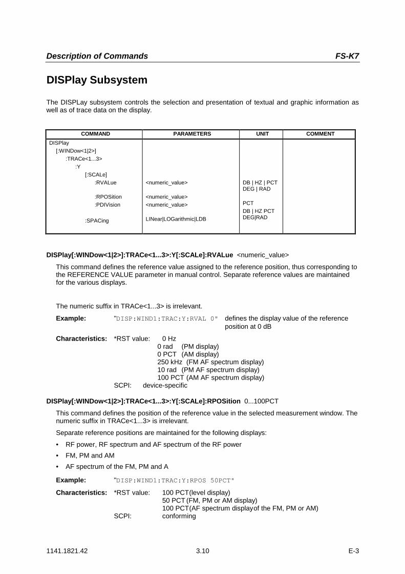
DISPlay[:WINDow<1|2>]:TRACe<1...3>:Y[:SCALe]:RVALue <numeric_value>
This command defines the reference value assigned to the reference position, thus corresponding tothe REFERENCE VALUE parameter in manual control. Separate reference values are maintainedfor the various displays.
The numeric suffix in TRACe<1...3> is irrelevant.
Example: "DISP:WIND1:TRAC:Y:RVAL 0" defines the display value of the referenceposition at 0 dB
Characteristics: *RST value: 0 Hz0 rad (PM display)0 PCT (AM display)250 kHz (FM AF spectrum display)10 rad (PM AF spectrum display)100 PCT (AM AF spectrum display)
SCPI: device-specific
DISPlay[:WINDow<1|2>]:TRACe<1...3>:Y[:SCALe]:RPOSition 0...100PCT
This command defines the position of the reference value in the selected measurement window. Thenumeric suffix in TRACe<1...3> is irrelevant.
Separate reference positions are maintained for the following displays:
• RF power, RF spectrum and AF spectrum of the RF power• FM, PM and AM• AF spectrum of the FM, PM and A
Example: "DISP:WIND1:TRAC:Y:RPOS 50PCT"
Characteristics: *RST value: 100 PCT(level display)50 PCT (FM, PM or AM display)100 PCT(AF spectrum displayof the FM, PM or AM)
SCPI: conforming

Description of Commands FS-K7
1141.1821.42 3.11 E-3
DISPlay[:WINDow<1|2>]:TRACe<1...3>:Y[:SCALe]:PDIVision <numeric_value>
This command defines the scaling of the Y-axis in the current unit.
Separate scalings are maintained for the following displays:
• FM display• PM display• AM display• Logarithmic AF spectrum display
The numeric suffix in TRACe<1...3> is irrelevant.
Example: "DISP:WIND1:TRAC:Y:PDIV 10KHz" 'Set Y scale to'10 kHz/div.
Characteristics: *RST value: *RST value: 50 kHz(FM display)2 rad (PM display)20 PCT (AM display)10 dB (AF spectrum display)
SCPI: conforming
Mode: FM
This command is only available with option FS-K7 (FM Demodulator).
DISPlay[:WINDow<1|2>]:TRACe<1...3>:Y:SPACing LINear | LOGarithmic | LDB
This command switches between linear and logarithmic display in the selected window. In the caseof linear display, it is also possible to switch between unit % (command DISP:WIND:TRAC:Y:SPACLIN) and unit dB (command DISP:WIND:TRAC:Y:SPAC LDB).
In the case of AF spectrum displays, only the parameters LINear and LOGarithmic are permitted.
The numeric suffix for TRACe<1...3> is irrelevant.
Example: "DISP:WIND1:TRAC:Y:SPAC LIN"
Characteristics: *RST value: LOGarithmicSCPI: conforming

Description of Commands FS-K7
1141.1821.42 3.12 E-3
INSTrument Subsystem
The INSTrument subsystem selects the operating mode of the unit either via text parameters or fixednumbers.
COMMAND PARAMETERS UNIT COMMENTINSTrument
[:SELect]:NSELect
SANalyzer| ADEMod |<numeric_value>
INSTrument[:SELect] SANalyzer | ADEMod |
This command switches between the operating modes by means of text parameters.
Parameter:ADEMod: FM demodulator modeSANalyzer: Spectrum analysis mode
Example: "INST SAN" Switch to SPECTRUM mode
Characteristics: *RST value: SANalyzerSCPI: conforming
Switching to ADEMod is only possible with option FM Demodulator FS-K7 installed.
INSTrument:NSELect 1| 3 This command switches between the operating modes by means of numbers.
Parameter: 1: Spectrum analysis mode
3: FM demodulator mode
Example: "INST:NSEL 1" Switch to SPECTRUM mode
Characteristics: *RST value: 1SCPI: conforming
Description of Commands FS-K7
1141.1821.42 3.13 E-3
SENSe Subsystem
The SENSe subsystem is organized in several subsystems. The commands of these subsystemsdirectly control device-specific settings; they do not refer to the signal characteristics of themeasurement signal.The SENSe subsystem controls the essential parameters of the analyzer. In accordance with the SCPIstandard, the keyword "SENSe" is optional for this reason, i.e. it is not necessary to include the SENSenode in command sequences.
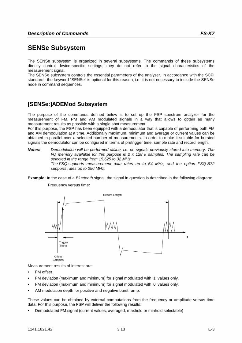
[SENSe:]ADEMod SubsystemThe purpose of the commands defined below is to set up the FSP spectrum analyzer for themeasurement of FM, PM and AM modulated signals in a way that allows to obtain as manymeasurement results as possible with a single shot measurement.For this purpose, the FSP has been equipped with a demodulator that is capable of performing both FMand AM demodulation at a time. Additionally maximum, minimum and average or current values can beobtained in parallel over a selected number of measurements. In order to make it suitable for burstedsignals the demodulator can be configured in terms of pretrigger time, sample rate and record length.
Notes: Demodulation will be performed offline, i.e. on signals previously stored into memory. TheI/Q memory available for this purpose is 2 x 128 k samples. The sampling rate can beselected in the range from 15.625 to 32 MHz.The FSQ supports measurement data rates up to 64 MHz, and the option FSQ-B72supports rates up to 256 MHz.
Example: In the case of a Bluetooth signal, the signal in question is described in the following diagram:
Frequency versus time:
t
Record Length
TriggerSignal
OffsetSamples
Measurement results of interest are:• FM offset• FM deviation (maximum and minimum) for signal modulated with ‘1‘ values only.• FM deviation (maximum and minimum) for signal modulated with ‘0‘ values only.• AM modulation depth for positive and negative burst ramp.
These values can be obtained by external computations from the frequency or amplitude versus timedata. For this purpose, the FSP will deliver the following results:• Demodulated FM signal (current values, averaged, maxhold or minhold selectable)

Description of Commands FS-K7
1141.1821.42 3.14 E-3
• Demodulated AM signal (current values, averaged, maxhold or minhold selectable)• FM offset (current value or averaged selectable)The following settings are required on the FSP:• Types of demodulation to be performed simultaneously (AM/FM)• Sampling rate• Record length• Trigger source (free run/external)• Pretrigger samples• Number of measurements for average/maxhold/minhold
In addition, the required measurement results need to be configured for each type of demodulation. TheFSP can simultaneously determine multiple types of demodulation with a maximum of 3 different resulttypes. The following result types can be selected:• WRITeThe current measurement results are determined.• AVERageThe measurement results are averaged over a specified number of measurements• MAXHoldThe maximum result values are determined over a specified number of measurements• MINHoldThe minimum result values are determined over a specified number of measurements
In practice, the commands defined below are used as follows:The instrument is set first. Then a measurement is started and the result list read in aftersynchronization to the end of the measurement. This method permits the control computer to be usedfor other tasks while the FSP is performing the measurement.
Note: Analog demodulation is only available for screen A. Therefore, it is not permissible to enter"SENSe2..." for the commands of the SENSe:ADEMod subsystem.
COMMAND PARAMETERS UNIT COMMENT [SENSe<1|2>]
:ADEMod:AF
:COUPling:CENTer:SPAN
:FULL:STARt:STOP
:BANDwidth:DEModulation
:BWIDth:DEModulation
:MTIMe:RLENgth?[:STATe]:SET
:SRATe?:ZOOM
[:STATe]:STARt
AC | DC<numeric_value><numeric_value>--<numeric_value><numeric_value>
<numeric_value>
<numeric_value><numeric_value>
<Boolean><numeric_value>,<numeric_value>,IMMediate | EXTernal | IFPower |RFPower | AF | AM |AMRelative | FM | PM,POSitive | NEGative,<numeric_value>,<numeric_value>
<Boolean><numeric_value>
HZHZ--HZHZ
HZ
HZS
HZ,--,--,
--,--,--
S
query only
query only

Description of Commands FS-K7
1141.1821.42 3.15 E-3
[SENSe:]ADEMod:AF:COUPling AC | DCThis command selects the coupling of the AF path.
Example: "ADEM:AF:COUP DC" 'Switch on DC coupling.
Characteristics: *RST value: ACSCPI: device-specific
[SENSe:]ADEMod:BANDwidth | BWIDth:DEModulation<numeric_value>This command defines the demodulation bandwidth for analog demodulation. Depending on theselected demodulation bandwidth, the instrument selects the required sampling rate.
The available values of the demodulation bandwidths are defined by the sampling rates.Demodulation
bandwidthSampling rate Comment
120 MHz 256 MHz with FSQ-B72 only
50 MHz/
85 MHz (1)128 MHz with FSQ-B72 only
30 MHz 64 MHz with FSQ only
18 MHz 32 MHz with FSQ only
10 MHz 32 MHz
8 MHz 16 MHz
5 MHz 8 MHz
3 MHz 4 MHz
1,6 MHz 2 MHz
800 kHz 1 MHz
400 kHz 500 kHz
200 kHz 250 kHz
100 kHz 125 kHz
50 kHz 62.5 kHz
25 kHz 31.25 kHz
12.5 kHz 15.625 kHz
6.4 kHz 7.8125 kHz
3.2 kHz 3.90625 kHz
1.6 kHz 1.953125 kHz
800 Hz 976.5625 Hz
400 Hz 488.28125 Hz
200 Hz 244.140625 Hz
100 Hz 122.0703125 Hz(1) The demodulation bandwidth at a sampling rate of 128 MHz depends on the center frequency that
has been set. At a center frequency of =3.6 GHz, the demodulation bandwidth is 50 MHz; athigher center frequencies, it is 85 MHz.
Example: "ADEM:BAND:DEM 1MHz" Set test bandwidth to 1 MHz.
Characteristics: *RST value: 5 MHzSCPI: device-specific

Description of Commands FS-K7
1141.1821.42 3.16 E-3
[SENSe:]ADEMod:MTIMe<numeric_value>
This command sets the measuring time for the analog demodulation.
Example: "ADEM:MTIM 62. 5us" 'Set measurement time to 62.5 µs.
Characteristics: *RST value: 62. 5usSCPI: device-specific
[SENSe:]ADEMod:RLENgth?This command returns the currently set record length for the analog demodulation.
Example: "ADEM:RLEN?" Return the current record length.
Characteristic: *RST value: -SCPI: device-specific
[SENSe:]ADEMod:AF:SPAN <numeric_value>
This command sets the span for the display of the AF spectrum.
The span is limited to half the measurement bandwidth of analog demodulation(SENS:ADEM:BAND).
Example: "ADEM ON" 'Switch on FM demodulator"CALC:FEED 'XTIM:FM:AFSP' 'Set "FM AF spectrum" display
or"CALC:FEED 'XTIM:RFP:AFSP''Switch on "AF spectrum of the
'RF power signal" display"ADEM:BAND 5 MHz" 'Set meas. bandwidth to 5 MHz"ADEM:AF:CENT 500kHz" 'Set AF center frequency to 500 kHz"ADEM:AF:SPAN 200kHz" 'Set AF span to 200 kHz
Characteristics: *RST value: 2.5 MHzSCPI: device-specific
[SENSe:]ADEMod:AF:SPAN:FULLThis command sets the maximum span for the display of the AF spectrum.
The maximum span corresponds to half the measurement bandwidth of analog demodulation(SENS:ADEM:BAND).
Example: "ADEM ON" 'Switch on FM demodulator"CALC:FEED 'XTIM:FM:AFSP' 'Switch on "FM AF spectrum" display
or"CALC:FEED 'XTIM:RFP:AFSP' 'Switch on "AF spectrum of the
'RF power signal" display"ADEM:BAND 5 MHz" 'Set meas. bandwidth to 5 MHz"ADEM:AF:SPAN:FULL" 'Set AF span to 2.5 MHz
Characteristics: *RST value: -SCPI: device-specific

Description of Commands FS-K7
1141.1821.42 3.17 E-3
[SENSe:]ADEMod:AF:CENTer <numeric_value>
This command sets the center frequency for the display of the AF spectrum.
Example: "ADEM ON" 'Switch on FM demodulator"CALC:FEED 'XTIM:FM:AFSP' 'Switch on "FM AF spectrum" display
or"CALC:FEED 'XTIM:RFP:AFSP''Switch on "AF spectrum of the
'RF power signal" display"ADEM:BAND 5 MHz" 'Set meas. bandwidth to 5 MHz"ADEM:AF:CENT 500kHz" 'Set AF center frequency to 500 kHz"ADEM:AF:SPAN 200kHz" 'Set AF span to 200 kHz
Characteristics: *RST value: 1.25 MHzSCPI: device-specific
[SENSe:]ADEMod:AF:STARt <numeric_value>
This command sets the start frequency for the display of the AF spectrum.
Example: "ADEM ON" 'Switch on FM demodulator"CALC:FEED 'XTIM:FM:AFSP' 'Switch on "FM AF spectrum" display
or"CALC:FEED 'XTIM:RFP:AFSP''Switch on "AF spectrum of the
'RF power signal" display"ADEM:BAND 5 MHz" 'Set meas. bandwidth to 5 MHz"ADEM:AF:STAR 0kHz" 'Set AF start frequency to 0 kHz"ADEM:AF:STOP 500kHz" 'Set AF stop frequency to 500 kHz
Characteristics: *RST value: 0 MHzSCPI: device-specific
[SENSe:]ADEMod:AF:STOP <numeric_value>
This command sets the stop frequency for the display of the AF spectrum.The stop frequency is limited to half the measurement bandwidth of analog demodulation(SENS:ADEM:BAND).
Example: "ADEM ON" 'Switch on FM demodulator"CALC:FEED 'XTIM:FM:AFSP' 'Switch on "FM AF spectrum" display
or"CALC:FEED 'XTIM:RFP:AFSP''Switch on "AF spectrum of the
'RF power signal" display"ADEM:BAND 5 MHz" 'Set meas. bandwidth to 5 MHz"ADEM:AF:STAR 0kHz" 'Set AF start frequency to 0 kHz"ADEM:AF:STOP 500kHz" 'Set AF stop frequency to 500 kHz
Characteristics: *RST value: 2.5 MHzSCPI: device-specific
Description of Commands FS-K7
1141.1821.42 3.18 E-3
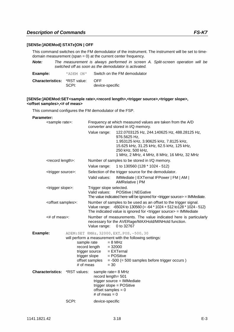
[SENSe:]ADEMod[:STATe]ON | OFFThis command switches on the FM demodulator of the instrument. The instrument will be set to time-domain measurement (span = 0) at the current center frequency.Note: The measurement is always performed in screen A. Split-screen operation will be
switched off as soon as the demodulator is activated.
Example: "ADEM ON" Switch on the FM demodulator
Characteristics: *RST value: OFFSCPI: device-specific
[SENSe:]ADEMod:SET<sample rate>,<record length>,<trigger source>,<trigger slope>,<offset samples>,<# of meas>
This command configures the FM demodulator of the FSP.
Parameter:<sample rate>: Frequency at which measured values are taken from the A/D
converter and stored in I/Q memory.Value range: 122.0703125 Hz, 244.140625 Hz, 488.28125 Hz,
976.5625 Hz,1.953125 kHz, 3.90625 kHz, 7.8125 kHz,15.625 kHz, 31.25 kHz, 62.5 kHz, 125 kHz,250 kHz, 500 kHz,1 MHz, 2 MHz, 4 MHz, 8 MHz, 16 MHz, 32 MHz
<record length>: Number of samples to be stored in I/Q memory.Value range: 1 to 130560 (128 * 1024 - 512)
<trigger source>: Selection of the trigger source for the demodulator.Valid values: IMMediate | EXTernal IFPower | FM | AM |
AMRelative | PM<trigger slope>: Trigger slope selected.
Valid values: POSitive | NEGativeThe value indicated here will be ignored for <trigger source> = IMMediate.
<offset samples>: Number of samples to be used as an offset to the trigger signal.Value range: -65024 to 130560 (= -64 * 1024 + 512 to128 * 1024 - 512)The indicated value is ignored for <trigger source> = IMMediate
<# of meas>: Number of measurements. The value indicated here is particularlynecessary for the AVERage/MAXHold/MINHold function.Value range: 0 to 32767
Example: ADEM:SET 8MHz,32000,EXT,POS,-500,30will perform a measurement with the following settings:
sample rate = 8 MHzrecord length = 32000trigger source = EXTernaltrigger slope = POSitiveoffset samples = -500 (= 500 samples before trigger occurs )# of meas = 30
Characteristics: *RST values: sample rate= 8 MHzrecord length= 501trigger source = IMMediatetrigger slope = POSitiveoffset samples = 0# of meas = 0
SCPI: device-specific

Description of Commands FS-K7
1141.1821.42 3.19 E-3
[SENSe:]ADEMod:SRATe?This command returns the currently set sampling rate for the analog demodulation.
Example: "ADEM:SRAT?" Return the current sampling rate.
Characteristics: *RST value: -SCPI: device-specific
[SENSe:]ADEMod:ZOOM[:STATe>] ON | OFF
This command switches the zoom function for the measurement data of the FM demodulator on oroff. Depending on the selected measurement time and demodulation bandwidth, more measurementpoints are captured than can be shown on the display.
If the zoom function has been switched on, exactly 501 (FSP) or 625 (FSU and FSQ) measurementpoints from the measured value memory will be shown starting at the time defined with[SENS:]ADEM:ZOOM:STARt.
If the zoom function has been switched off, all measurement points will be compressed down to thenumber of points available on the display by means of data reduction.
Example: "ADEM:ZOOM ON" Switch on the zoom function.
Characteristics: *RST value: OFFSCPI: device-specific
[SENSe:]ADEMod:ZOOM:STARt 0 s to measurement time
This command selects the start time for displaying the individual measurement values of the FMdemodulator. The maximum value depends on the measurement time set in the instrument; thisvalue can be queried with ADEM:ZOOM:START? MAX.If the zoom function has been switched on, 501 (FSP) or 625 (FSU and FSQ) measurement pointswill be displayed starting at the time that has been set.
Example: "ADEM:ZOOM ON" Switch on zoom function"ADEM:ZOOM:STAR 500us" Set display starting point to 500 µs
Characteristics: *RST value: 0 sSCPI: device-specific
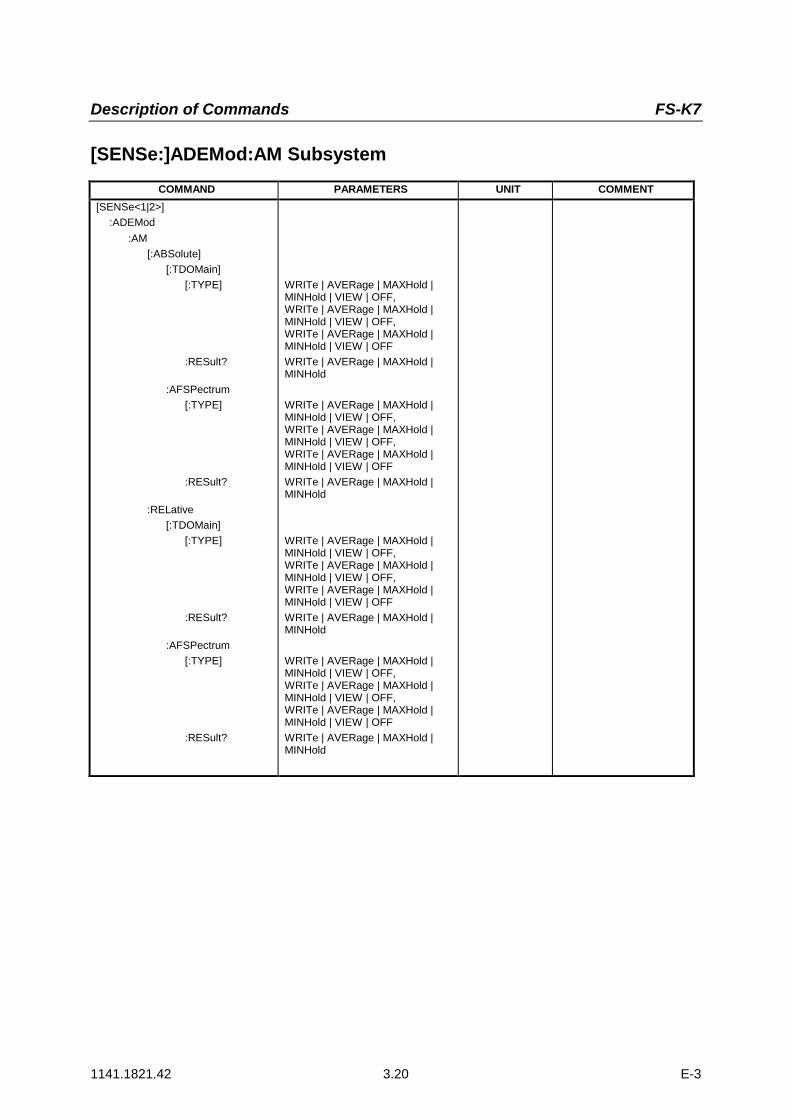
Description of Commands FS-K7
1141.1821.42 3.20 E-3
[SENSe:]ADEMod:AM SubsystemCOMMAND PARAMETERS UNIT COMMENT
[SENSe<1|2>]:ADEMod
:AM[:ABSolute]
[:TDOMain][:TYPE]
:RESult?
:AFSPectrum[:TYPE]
:RESult?
:RELative[:TDOMain]
[:TYPE]
:RESult?
:AFSPectrum[:TYPE]
:RESult?
WRITe | AVERage | MAXHold |MINHold | VIEW | OFF,WRITe | AVERage | MAXHold |MINHold | VIEW | OFF,WRITe | AVERage | MAXHold |MINHold | VIEW | OFFWRITe | AVERage | MAXHold |MINHold
WRITe | AVERage | MAXHold |MINHold | VIEW | OFF,WRITe | AVERage | MAXHold |MINHold | VIEW | OFF,WRITe | AVERage | MAXHold |MINHold | VIEW | OFFWRITe | AVERage | MAXHold |MINHold
WRITe | AVERage | MAXHold |MINHold | VIEW | OFF,WRITe | AVERage | MAXHold |MINHold | VIEW | OFF,WRITe | AVERage | MAXHold |MINHold | VIEW | OFFWRITe | AVERage | MAXHold |MINHold
WRITe | AVERage | MAXHold |MINHold | VIEW | OFF,WRITe | AVERage | MAXHold |MINHold | VIEW | OFF,WRITe | AVERage | MAXHold |MINHold | VIEW | OFFWRITe | AVERage | MAXHold |MINHold
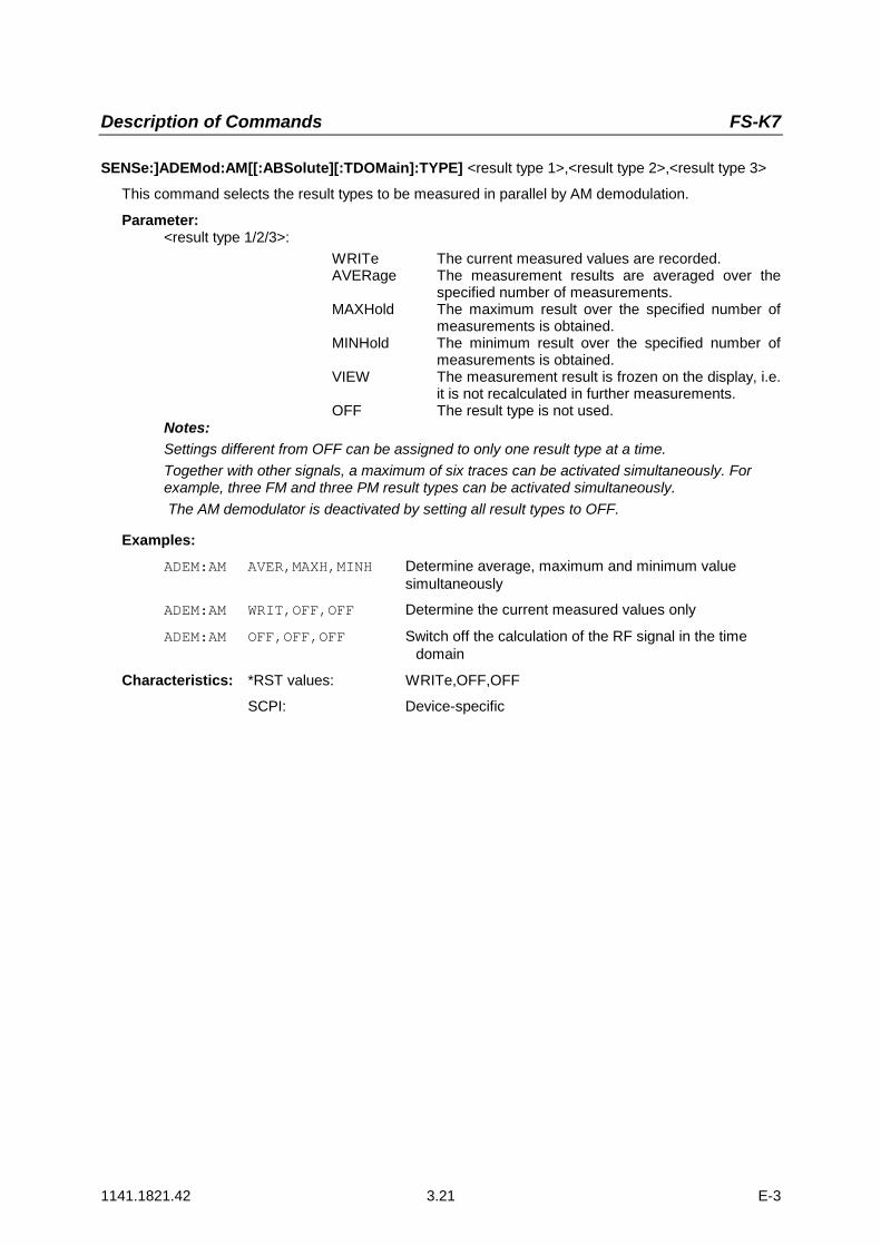
Description of Commands FS-K7
1141.1821.42 3.21 E-3
SENSe:]ADEMod:AM[[:ABSolute][:TDOMain]:TYPE] <result type 1>,<result type 2>,<result type 3>
This command selects the result types to be measured in parallel by AM demodulation.
Parameter:<result type 1/2/3>:
WRITe The current measured values are recorded.AVERage The measurement results are averaged over the
specified number of measurements.MAXHold The maximum result over the specified number of
measurements is obtained.MINHold The minimum result over the specified number of
measurements is obtained.VIEW The measurement result is frozen on the display, i.e.
it is not recalculated in further measurements.OFF The result type is not used.
Notes:Settings different from OFF can be assigned to only one result type at a time.Together with other signals, a maximum of six traces can be activated simultaneously. Forexample, three FM and three PM result types can be activated simultaneously. The AM demodulator is deactivated by setting all result types to OFF.
Examples:ADEM:AM AVER,MAXH,MINH Determine average, maximum and minimum value
simultaneously
ADEM:AM WRIT,OFF,OFF Determine the current measured values only
ADEM:AM OFF,OFF,OFF Switch off the calculation of the RF signal in the timedomain
Characteristics: *RST values: WRITe,OFF,OFF
SCPI: Device-specific

Description of Commands FS-K7
1141.1821.42 3.22 E-3
[SENSe:]ADEMod:AM[:ABSolute][:TDOMain]:RESult?<result type>This command reads the result data obtained by AM demodulation depending on the type indicatedas a parameter. The data format of the output data is defined by the FORMat command.
Note:Traces cannot be queried when VIEW is active.
Parameter:<result type>:
WRITe The current measured values are recorded.AVERage The measurement results averaged over the
specified number of measurements are obtained.MAXHold The maximum result is determined over the
specified number of measurements.MINHold The minimum result is determined over the specified
number of measurements.Note:The result type indicated must be one that was configured with the command[SENSe:]ADEMod:AM[:ABSolute][:TDOMain] [:TYPE]. Otherwise, a query error will begenerated.
Return values:
ASCII format (FORMat ASCII):In this case, the command will return a list of comma-separated values (CSV) of the measuredvalues in floating point format. The output unit is dBm (logarithmic display) or V (lineardisplay).
Binary format (FORMat REAL,32):In this case, the command will return binary data (Definite Length Block Data according toIEEE 488.2), with each measured value formatted in 32-bit IEEE 754 floating point format. Theresponse string will have the following structure:
#41024<value1><value2>...<value n>
with
#4 Number of digits in the following number of data bytes (= 4 in the example)
1024 Number of following data bytes (# of DataBytes, = 1024 in the example)
<value x> 4-byte floating point value
Examples:ADEM:SET 8MHz,32000,EXT,POS,-500,30 'Set up demodulator parametersADEM:FAM AVER,MAXH,MINH 'Select results to measureADEM ON 'Switch on demodulatorINIT;*WAI 'Start measurement and wait for endFORM ASC 'Select output formatADEM:FM:RES? AVER 'Read average resultsADEM:FM:RES? MAXH 'Read MAXHold resultsADEM:FM:RES? MINH 'Read MINHold results
Characteristics: *RST value: -SCPI: device-specific

Description of Commands FS-K7
1141.1821.42 3.23 E-3
[SENSe:]ADEMod:AM[:ABSolute]:AFSPectrum[:TYPE] <result type 1>,<result type 2>,<result type 3>
This command selects the AF spectrum result types of the RF signal in the time domain to be measuredsimultaneously.
Parameters: <result type 1/2/3>: WRITe The current measured values are recorded.AVERage The measurement results are averaged over the
specified number of measurements.MAXHold The maximum result over the specified number
of measurements is determined.MINHold The minimum result over the specified number of
measurements is determined.VIEW The measurement result is frozen on the display,
i.e. it is not recalculated in further measurements.OFF The result type is not used.
Note:Settings different from OFF can be assigned to only one result type at a time.Together with other signals, a maximum of six traces can be activated simultaneously. Forexample, three FM and three PM result types can be activated simultaneously.If all result types are set to OFF, no AF spectrum of the RF signal in the time domain will becalculated.The result type AF spectrum of the RF signal in the time domain cannot be activatedsimultaneously with other AF spectra.
Examples:ADEM:AM:AFSP AVER,MAXH,MINH Determine average, maximum and minimum
simultaneouslyADEM:AM:AFSP WRIT,OFF,OFF Determine only the current measurement resultsADEM:AM:AFSP OFF,OFF,OFF Switch off calculation of the AF spectrum
Characteristics: *RST values: OFF,OFF,OFFSCPI: device-specific

Description of Commands FS-K7
1141.1821.42 3.24 E-3
[SENSe:]ADEMod:AM[:ABSolute]:AFSPectrum:RESult? <result type>
This command reads out the result data of the AF spectrum of the RF signal in the time domain for thespecified result type. The format of the output data is defined using the FORMat command.
Note: Traces cannot be queried when VIEW is active.
Parameters: <result type>: WRITe The current measured values are returned.AVERage The measurement results averaged over the
specified number of measurements are returned.MAXHold The maximum result over the specified number of
measurements is returned.MINHold The minimum result over the specified number of
measurements is returned.Note: The specified result type must be one that was configured with the command
[SENSe:]ADEMod:AM[:ABSolute]:AFSPectrum[:TYPE]. Otherwise, a query errorwill be generated.
Return values:
ASCII format (FORMat ASCII):In this case, the command will return a list of comma-separated values (CSV) of the measuredvalues in floating point format. The output unit is dBm (logarithmic display) or V (linear display).
Binary format (FORMat REAL,32):In this case, the command will return binary data (Definite Length Block Data according toIEEE 488.2), with each measured value formatted in 32-bit IEEE 754 floating point format. Theresponse string will have the following structure:
#41024<value1><value2>...<value n>where#4 Number of digits in the following number of data bytes (= 4 in the example)
1024 Number of following data bytes (# of DataBytes = 1024 in the example)
<value x> 4-byte floating point value
Examples:ADEM:SET 8MHz,32000,EXT,POS,-500,30 'Set demodulatorADEM:FM AVER,MAXH,MINH 'Select FM results to be measuredADEM:AM WRIT,OFF,OFF 'Select results of the RF signal to be
'measured in the time domainADEM:AM:AFSP WRIT,OFF,OFF 'Select the AF spectrum results of the
'RF signal to be measured in the time'domain
ADEM ON 'Switch on demodulatorINIT;*WAI 'Start measurement and wait for endFORM ASC 'Select output formatADEM:FM:RES? AVER 'Read FM average value result dataADEM:FM:RES? MAXH 'Read FM MAXHold result dataADEM:FM:RES? MINH 'Read FM MINHold result dataADEM:AM:RES? WRIT 'Read current AM result dataADEM:AM:AFSP:RES? WRIT 'Read current AF spectrum result
'data of the RF signal in the time'domain
Characteristics: *RST value: -SCPI: device-specific
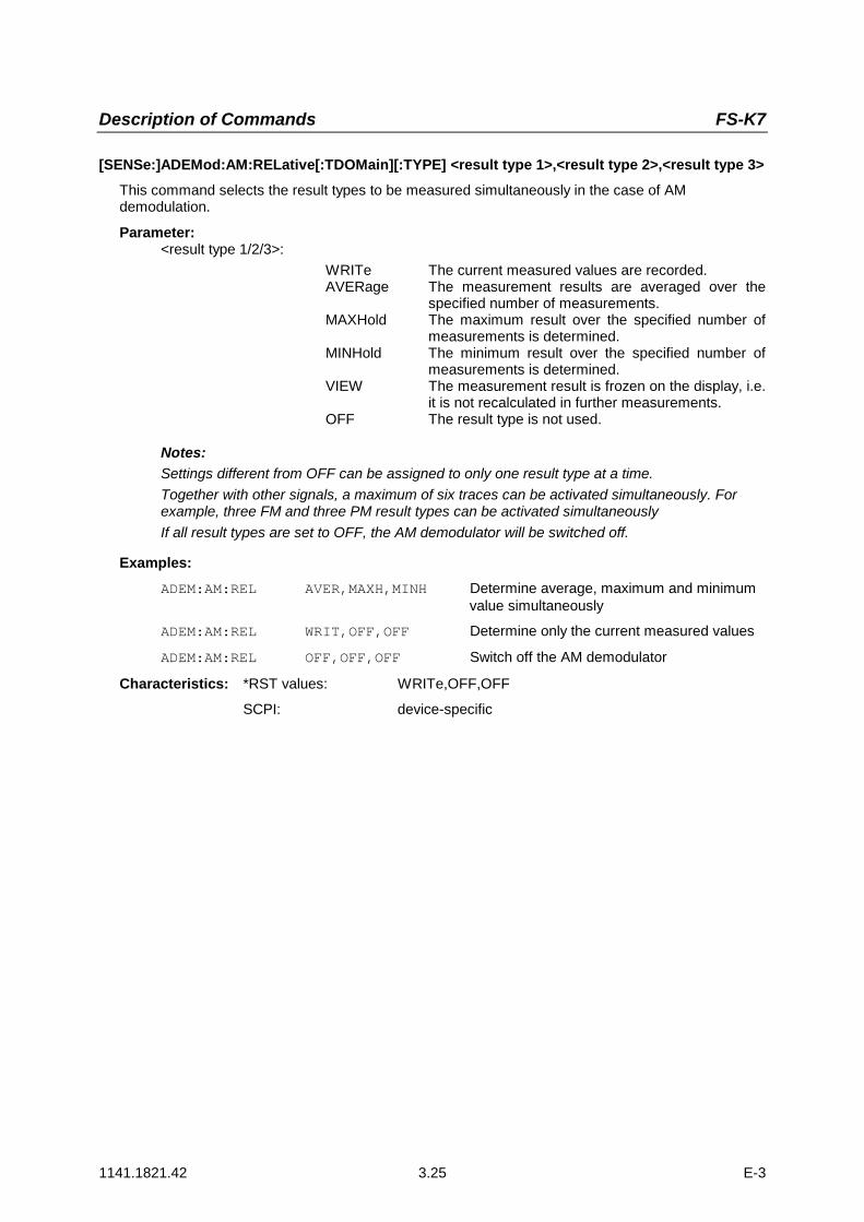
Description of Commands FS-K7
1141.1821.42 3.25 E-3
[SENSe:]ADEMod:AM:RELative[:TDOMain][:TYPE] <result type 1>,<result type 2>,<result type 3>This command selects the result types to be measured simultaneously in the case of AMdemodulation.
Parameter:<result type 1/2/3>:
WRITe The current measured values are recorded.AVERage The measurement results are averaged over the
specified number of measurements.MAXHold The maximum result over the specified number of
measurements is determined.MINHold The minimum result over the specified number of
measurements is determined.VIEW The measurement result is frozen on the display, i.e.
it is not recalculated in further measurements.OFF The result type is not used.
Notes:Settings different from OFF can be assigned to only one result type at a time.Together with other signals, a maximum of six traces can be activated simultaneously. Forexample, three FM and three PM result types can be activated simultaneouslyIf all result types are set to OFF, the AM demodulator will be switched off.
Examples:ADEM:AM:REL AVER,MAXH,MINH Determine average, maximum and minimum
value simultaneously
ADEM:AM:REL WRIT,OFF,OFF Determine only the current measured values
ADEM:AM:REL OFF,OFF,OFF Switch off the AM demodulator
Characteristics: *RST values: WRITe,OFF,OFF
SCPI: device-specific

Description of Commands FS-K7
1141.1821.42 3.26 E-3
[SENSe:]ADEMod:AM:RELative[:TDOMain]:RESult?<result type>
This command reads out the result data of the AM demodulation for the specified result type. The format ofthe output data is defined using the FORMat command.
Note: Traces cannot be queried when VIEW is active.<result type>:
WRITe The current measured values are returned.AVERage The measurement results averaged over the
specified number of measurements are returned.MAXHold The maximum result over the specified number of
measurements is returned.MINHold The minimum result over the specified number of
measurements is returned.Note: The specified result type must be one that was configured with the command
[SENSe:]ADEMod:AM:RELative[:TDOMain][:TYPE]. Otherwise, a query error willbe generated.
Return values:
ASCII format (FORMat ASCII):In this case, the command will return a list of comma-separated values (CSV) of the measuredvalues in floating point format. The output unit is %.
Binary format (FORMat REAL,32):In this case, the command will return binary data (Definite Length Block Data according toIEEE 488.2), with each measured value formatted in 32-bit IEEE 754 floating point format. Theresponse string will have the following structure:#41024<value1><value2>...<value n>where#4 Number of digits in the following number of data bytes (= 4 in the example)1024 Number of following data bytes (# of DataBytes = 1024 in the example)<value x> 4-byte floating point value
Examples:ADEM:SET 8MHz,32000,EXT,POS,-500,30 'Set demodulatorADEM:FM AVER,MAXH,MINH 'Select FM results to be measuredADEM:AM:REL WRIT,OFF,OFF 'Select AM results to be measuredADEM ON 'Switch on demodulatorINIT;*WAI 'Start measurement and wait for endFORM ASC 'Select output formatADEM:FM:RES? AVER 'Read FM average result dataADEM:FM:RES? MAXH 'Read FM MAXHold result dataADEM:FM:RES? MINH 'Read FM MINHold result dataADEM:AM:REL:RES? WRIT 'Read current AM result data
Characteristics: *RST value: -SCPI: device-specific
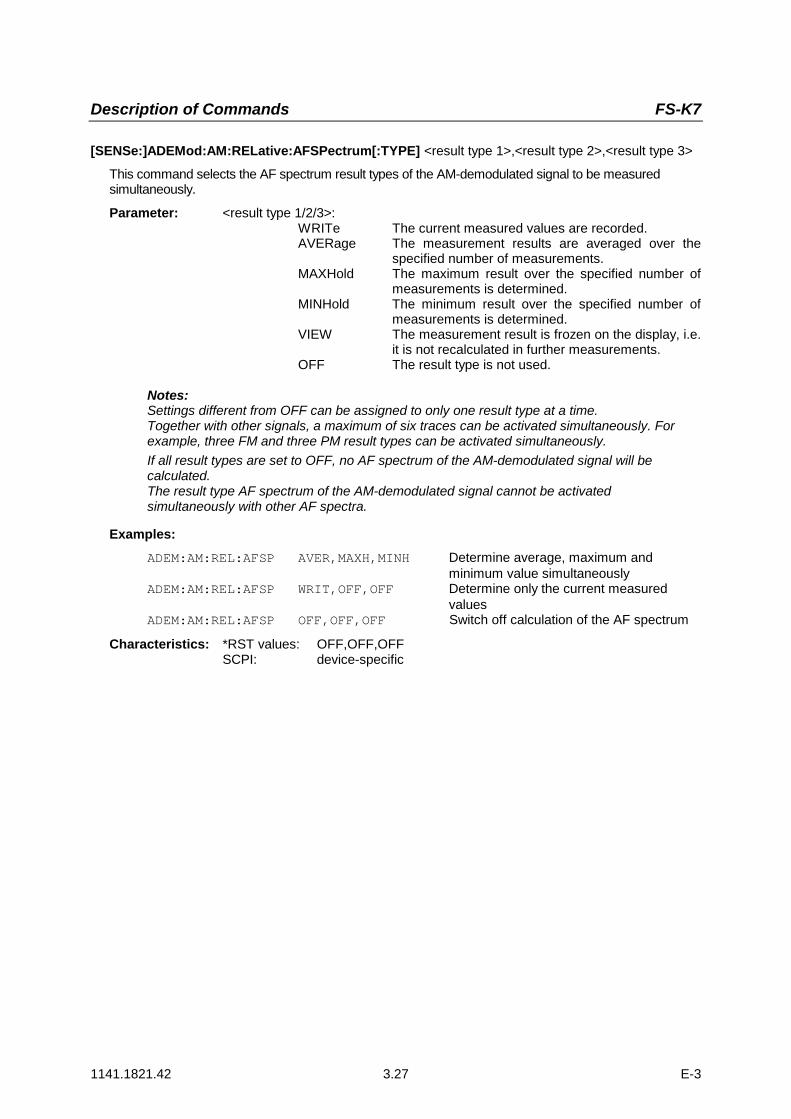
Description of Commands FS-K7
1141.1821.42 3.27 E-3
[SENSe:]ADEMod:AM:RELative:AFSPectrum[:TYPE] <result type 1>,<result type 2>,<result type 3>
This command selects the AF spectrum result types of the AM-demodulated signal to be measuredsimultaneously.
Parameter: <result type 1/2/3>:WRITe The current measured values are recorded.AVERage The measurement results are averaged over the
specified number of measurements.MAXHold The maximum result over the specified number of
measurements is determined.MINHold The minimum result over the specified number of
measurements is determined.VIEW The measurement result is frozen on the display, i.e.
it is not recalculated in further measurements.OFF The result type is not used.
Notes:Settings different from OFF can be assigned to only one result type at a time.Together with other signals, a maximum of six traces can be activated simultaneously. Forexample, three FM and three PM result types can be activated simultaneously.If all result types are set to OFF, no AF spectrum of the AM-demodulated signal will becalculated.The result type AF spectrum of the AM-demodulated signal cannot be activatedsimultaneously with other AF spectra.
Examples:ADEM:AM:REL:AFSP AVER,MAXH,MINH Determine average, maximum and
minimum value simultaneouslyADEM:AM:REL:AFSP WRIT,OFF,OFF Determine only the current measured
valuesADEM:AM:REL:AFSP OFF,OFF,OFF Switch off calculation of the AF spectrum
Characteristics: *RST values: OFF,OFF,OFFSCPI: device-specific

Description of Commands FS-K7
1141.1821.42 3.28 E-3
[SENSe:]ADEMod:AM:RELative:AFSPectrum:RESult? <result type>
This command reads out the result data of the AF spectrum of the AM-demodulated signal for the specifiedresult type. The format of the output data is defined using the FORMat command.Note: Traces cannot be queried when VIEW is active.
Parameter: <result type>: WRITe The current measured values are returned.AVERage The measurement results averaged over the
specified number of measurements are returned.MAXHold The maximum result over the specified number of
measurements is returned.MINHold The minimum result over the specified number of
measurements is returned.
Note: The specified result type must be one that was configured with the command[SENSe:]ADEMod:AM:RELative:AFSPectrum[:TYPE]. Otherwise, a query errorwill be generated.
Return values:
ASCII format (FORMat ASCII):In this case, the command will return a list of comma-separated values (CSV) of the measuredvalues in floating point format. The output unit is dBm (logarithmic display) or % (lineardisplay).
Binary format (FORMat REAL,32):In this case, the command will return binary data (Definite Length Block Data according toIEEE 488.2), with each measured value formatted in 32-bit IEEE 754 floating point format. Theresponse string will have the following structure:
#41024<value1><value2>...<value n>where#4 Number of digits in the following number of data bytes (= 4 in the example)
1024 Number of following data bytes (# of DataBytes = 1024 in the example)
<value x> 4-byte floating point value
Examples:ADEM:SET 8MHz,32000,EXT,POS,-500,30 'Set demodulatorADEM:FM AVER,MAXH,MINH 'Select the FM results to be
'measuredADEM:AM:REL WRIT,OFF,OFF 'Select the AM results to be
'measuredADEM:AM:REL:AFSP WRIT,OFF,OFF 'Select the AF spectrum results of the
'demodulated AM signal to be measuredADEM ON 'Switch on demodulatorINIT;*WAI 'Start measurement and wait for endFORM ASC 'Select output formatADEM:FM:RES? AVER 'Read FM average value result dataADEM:FM:RES? MAXH 'Read FM MAXHold result dataADEM:FM:RES? MINH 'Read FM MINHold result dataADEM:AM:REL:RES? WRIT 'Read current AM result dataADEM:AM:REL:AFSP:RES? WRIT 'Read current AF spectrum result
'data of the demodulated AM signal
Characteristics: *RST value: -SCPI: device-specific
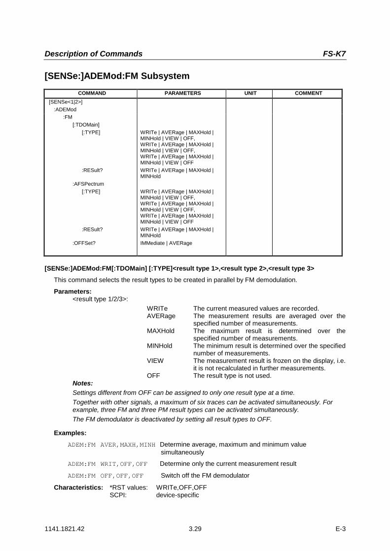
Description of Commands FS-K7
1141.1821.42 3.29 E-3
[SENSe:]ADEMod:FM SubsystemCOMMAND PARAMETERS UNIT COMMENT
[SENSe<1|2>]:ADEMod
:FM[:TDOMain]
[:TYPE]
:RESult?
:AFSPectrum[:TYPE]
:RESult?
:OFFSet?
WRITe | AVERage | MAXHold |MINHold | VIEW | OFF,WRITe | AVERage | MAXHold |MINHold | VIEW | OFF,WRITe | AVERage | MAXHold |MINHold | VIEW | OFFWRITe | AVERage | MAXHold |MINHold
WRITe | AVERage | MAXHold |MINHold | VIEW | OFF,WRITe | AVERage | MAXHold |MINHold | VIEW | OFF,WRITe | AVERage | MAXHold |MINHold | VIEW | OFFWRITe | AVERage | MAXHold |MINHoldIMMediate | AVERage
[SENSe:]ADEMod:FM[:TDOMain] [:TYPE]<result type 1>,<result type 2>,<result type 3>This command selects the result types to be created in parallel by FM demodulation.
Parameters:<result type 1/2/3>:
WRITe The current measured values are recorded.AVERage The measurement results are averaged over the
specified number of measurements.MAXHold The maximum result is determined over the
specified number of measurements.MINHold The minimum result is determined over the specified
number of measurements.VIEW The measurement result is frozen on the display, i.e.
it is not recalculated in further measurements.OFF The result type is not used.
Notes:Settings different from OFF can be assigned to only one result type at a time.Together with other signals, a maximum of six traces can be activated simultaneously. Forexample, three FM and three PM result types can be activated simultaneously.The FM demodulator is deactivated by setting all result types to OFF.
Examples:ADEM:FM AVER,MAXH,MINH Determine average, maximum and minimum value
simultaneously
ADEM:FM WRIT,OFF,OFF Determine only the current measurement result
ADEM:FM OFF,OFF,OFF Switch off the FM demodulator
Characteristics: *RST values: WRITe,OFF,OFFSCPI: device-specific
Description of Commands FS-K7
1141.1821.42 3.30 E-3
[SENSe:]ADEMod:FM[:TDOMain]:RESult?<result type>This command reads the result data obtained by FM demodulation depending on the type indicatedas a parameter. The data format of the output data is defined by the FORMat command.
Note: Traces cannot be queried when VIEW is active.
Parameter:<result type>:
WRITe The current trace data is recorded.AVERage The measurement results averaged over the
specified number of measurements are obtained.MAXHold The maximum result is determined over the
specified number of measurements.MINHold The minimum result is determined over the specified
number of measurements.Note:The specified result type must be one that was configured with the command[SENSe:]ADEMod:FM[:TYPE]. Otherwise, a query error will be generated.
Return values:
ASCII format (FORMat ASCII):In this case, the command will return a list of comma-separated values (CSV) of the measuredvalues in floating point format. The output unit is Hz.
Binary format (FORMat REAL,32):In this case, the command will return binary data (Definite Length Block Data according toIEEE 488.2), with each measured value formatted in 32-bit IEEE 754 floating point format. Theresponse string will have the following structure:
#41024<value1><value2>...<value n>
with
#4 Number of digits (= 4 in the example) of the following number of data bytes
1024 Number of following data bytes (# of DataBytes = 1024 in the example)
<value x> 4-byte floating point value
Examples:ADEM:SET 8MHz,32000,EXT,POS,-500,30 'Set demodulator 'parameters
ADEM:FM AVER,MAXH,MINH 'Select FM results to measure
ADEM:AM WRIT,OFF,OFF 'Select AM results to measure
ADEM ON 'Switch on demodulator
INIT;*WAI 'Start measurement and wait'for end
FORM ASC 'Select output format
ADEM:FM:RES? AVER 'Read FM average results
ADEM:FM:RES? MAXH 'Read FM MAXHold results
ADEM:FM:RES? MINH 'Read FM MINHold result data
ADEM:AM:RES? WRIT 'Read current AM results
Characteristics: *RST value: -SCPI: device-specific

Description of Commands FS-K7
1141.1821.42 3.31 E-3
[SENSe:]ADEMod:FM:AFSPectrum[:TYPE] <result type 1>,<result type 2>,<result type 3>
This command selects the AF spectrum result types of the FM-demodulated signal to be measuredsimultaneously.
Parameter: <result type 1/2/3>:WRITe The current measured values are recorded.AVERage The measurement results are averaged over the
specified number of measurements.MAXHold The maximum result over the specified number of
measurements is determined.MINHold The minimum result over the specified number of
measurements is determined.VIEW The measurement result is frozen on the display, i.e.
it is not recalculated in further measurements.OFF The result type is not used.
Notes:Settings different from OFF can be assigned to only one result type at a time.Together with other signals, a maximum of six traces can be activated simultaneously. Forexample, three FM and three PM result types can be activated simultaneously.If all result types are set to OFF, no AF spectrum of the FM-demodulated signal will becalculated.The result type AF spectrum of the FM-demodulated signal cannot be activatedsimultaneously with other AF spectra.
Examples:ADEM:FM:AFSP AVER,MAXH,MINH Determine average, maximum and minimum
value simultaneously
ADEM:FM:AFSP WRIT,OFF,OFF Determine only the current measured values
ADEM:FM:AFSP OFF,OFF,OFF Switch off calculation of the AF spectrum
Characteristics: *RST values: OFF,OFF,OFFSCPI: device-specific
[SENSe:]ADEMod:FM:AFSPectrum:RESult? <result type>
This command reads out the result data of the AF spectrum of the FM-demodulated signal for the specifiedresult type. The format of the output data is defined using the FORMat command.
Note:Traces cannot be queried when VIEW is active.
Parameter: <result type>:
WRITe The current measured values are returned.AVERage The measurement results averaged over the
specified number of measurements are returned.MAXHold The maximum result over the specified number of
measurements is returned.MINHold The minimum result over the specified number of
measurements is returned.Note:The specified result type must be one that was configured with the command[SENSe:]ADEMod:FM:AFSPectrum[:TYPE]. Otherwise, a query error will be generated.

Description of Commands FS-K7
1141.1821.42 3.32 E-3
Return values:
ASCII format (FORMat ASCII):In this case, the command will return a list of comma-separated values (CSV) of the measuredvalues in floating point format. The output unit is dBm (logarithmic display) or V (lineardisplay).
Binary format (FORMat REAL,32):In this case, the command will return binary data (Definite Length Block Data according toIEEE 488.2), with each measured value formatted in 32-bit IEEE 754 floating point format. Theresponse string will have the following structure:
#41024<value1><value2>...<value n>where#4 Number of digits in the following number of data bytes (= 4 in the example)
1024 Number of following data bytes (# of DataBytes = 1024 in the example)
<value x> 4-byte floating point value
Examples:ADEM:SET 8MHz,32000,EXT,POS,-500,30 'Set demodulator
ADEM:FM AVER,MAXH,MINH 'Select FM results to be measured
ADEM:AM:REL WRIT,OFF,OFF 'Select AM results to be measured
ADEM:FM:AFSP WRIT,OFF,OFF 'Select AF spectrum results of the'demodulated FM signal to be'measured
ADEM ON 'Switch on demodulator
INIT;*WAI 'Start measurement and wait for end
FORM ASC 'Select output format
ADEM:FM:RES? AVER 'Read FM average result data
ADEM:FM:RES? MAXH 'Read FM MAXHold result data
ADEM:FM:RES? MINH 'Read FM MINHold result data
ADEM:AM:RES? WRIT 'Read current AM result data
ADEM:FM:AFSP:RES? WRIT 'Read current AF spectrum result data'of the demodulated FM signal
Characteristics: *RST value: -SCPI: device-specific

Description of Commands FS-K7
1141.1821.42 3.33 E-3
[SENSe:]ADEMod:FM:OFFSet?<result type>This command calculates the FM offset of the current measured data set.
If averaging has been activated prior to data acquisition (using the command [SENSe:]ADEMod:FM[:TYPE]), the average FM offset can also be obtained by setting <result type> = AVERage. Theaverage FM offset obtained in this way differs from the one calculated byCALC:MARK:FUNC:ADEM:FERR?, since, for determination of the frequency deviation, themodulation is removed by means of lowpass filtering, producing results that are different from thoseobtained by averaging.
Parameters:<result type>:
IMMediate The current measurement results are used forcalculating the FM offset.
AVERage The measurement results averaged over thespecified number of measurements are used forcalculation of the FM offset.
Notes:If no average measurement has been active during the last measurement sequence, only thecommand [SENSe:]ADEMod:FM:OFFSet? IMMediate will return a valid result (data tocalculate the FM offset are taken from the last measured data set).
[SENSe:]ADEMod:FM:OFFSet? AVERage will cause a query error in this case.
Example:ADEM:SET 8MHz,32000,EXT,POS,-500,30 'Set demodulator to perform
'30 measurements
ADEM:FM AVER,OFF,OFF 'Set FM results to perform'averaging
ADEM:AM OFF,OFF,OFF 'Switch off AM demodulation
ADEM ON 'Switch on FM demodulator
INIT;*WAI 'Start measurement and wait'for end
ADEM:FM:OFFS? IMM 'Read FM offset of last'measurement of the sequence'of 30
ADEM:FM:OFFS? AVER 'Read FM offset averaged'over 30 measurements
Characteristics: *RST value: -
SCPI: device-specific

Description of Commands FS-K7
1141.1821.42 3.34 E-3
[SENSe:]ADEMod:PM SubsystemCOMMAND PARAMETERS UNIT COMMENT
[SENSe<1|2>]:ADEMod
:PM[:TDOMain]
[:TYPE]
:RESult?
:AFSPectrum[:TYPE]
:RESult?
:OFFSet?
WRITe | AVERage | MAXHold |MINHold | VIEW | OFF,WRITe | AVERage | MAXHold |MINHold | VIEW | OFF,WRITe | AVERage | MAXHold |MINHold | VIEW | OFFWRITe | AVERage | MAXHold |MINHold
WRITe | AVERage | MAXHold |MINHold | VIEW | OFF,WRITe | AVERage | MAXHold |MINHold | VIEW | OFF,WRITe | AVERage | MAXHold |MINHold | VIEW | OFFWRITe | AVERage | MAXHold |MINHoldIMMediate | AVERage
[SENSe:]ADEMod:PM[:TDOMain] [:TYPE]<result type 1>,<result type 2>,<result type 3>This command selects the result types to be created in parallel by PM demodulation.
Parameters:<result type 1/2/3>:
WRITe The current measured values are recorded.AVERage The measurement results are averaged over the
specified number of measurements.MAXHold The maximum result is determined over the
specified number of measurements.MINHold The minimum result is determined over the specified
number of measurements.VIEW The measurement result is frozen on the display, i.e.
it is not recalculated in further measurements.OFF The result type is not used.
Notes:Settings different from OFF can be assigned to only one result type at a time.Together with other signals, a maximum of six traces can be activated simultaneously. Forexample, three PM and three PM result types can be activated simultaneously.The PM demodulator is deactivated by setting all result types to OFF.
Examples:ADEM:PM AVER,MAXH,MINH Determine average, maximum and minimum value simultaneously
ADEM:PM WRIT,OFF,OFF Determine only the current measurement result
ADEM:PM OFF,OFF,OFF Switch off the PM demodulator
Characteristics: *RST values: WRITe,OFF,OFFSCPI: device-specific
Description of Commands FS-K7
1141.1821.42 3.35 E-3
[SENSe:]ADEMod:PM[:TDOMain]:RESult?<result type>This command reads the result data obtained by PM demodulation depending on the type indicatedas a parameter. The data format of the output data is defined by the FORMat command.
Note: Traces cannot be queried when VIEW is active.
Parameter:<result type>:
WRITe The current trace data is recorded.AVERage The measurement results averaged over the
specified number of measurements are obtained.MAXHold The maximum result is determined over the
specified number of measurements.MINHold The minimum result is determined over the specified
number of measurements.Note: The specified result type must be one that was configured with the command
[SENSe:]ADEMod:PM[:TYPE]. Otherwise, a query error will be generated.
Return values:
ASCII format (FORMat ASCII):In this case, the command will return a list of comma-separated values (CSV) of the measuredvalues in floating point format. The output unit depends on the unit selected - either RAD orDEG.
Binary format (FORMat REAL,32):In this case, the command will return binary data (Definite Length Block Data according toIEEE 488.2), with each measured value formatted in 32-bit IEEE 754 floating point format. Theresponse string will have the following structure:
#41024<value1><value2>...<value n>
with
#4 Number of digits (= 4 in the example) of the following number of data bytes
1024 Number of following data bytes (# of DataBytes = 1024 in the example)
<value x> 4-byte floating point value
Examples:ADEM:SET 8MHz,32000,EXT,POS,-500,30 'Set demodulator 'parameters
ADEM:PM AVER,MAXH,MINH 'Select PM results to measure
ADEM:AM WRIT,OFF,OFF 'Select AM results to measure
ADEM ON 'Switch on demodulator
INIT;*WAI 'Start measurement and wait'for end
FORM ASC 'Select output format
ADEM:PM:RES? AVER 'Read PM average results
ADEM:PM:RES? MAXH 'Read PM MAXHold results
ADEM:PM:RES? MINH 'Read PM MINHold result data
ADEM:AM:RES? WRIT 'Read current AM results
Characteristics: *RST value: -SCPI: device-specific
Description of Commands FS-K7
1141.1821.42 3.36 E-3
[SENSe:]ADEMod:PM:AFSPectrum[:TYPE] <result type 1>,<result type 2>,<result type 3>
This command selects the AF spectrum result types of the PM-demodulated signal to be measuredsimultaneously.
Parameter: <result type 1/2/3>:WRITe The current measured values are recorded.AVERage The measurement results are averaged over the
specified number of measurements.MAXHold The maximum result over the specified number of
measurements is determined.MINHold The minimum result over the specified number of
measurements is determined.VIEW The measurement result is frozen on the display, i.e.
it is not recalculated in further measurements.OFF The result type is not used.
Notes:Settings different from OFF can be assigned to only one result type at a time.Together with other signals, a maximum of six traces can be activated simultaneously. Forexample, three PM and three PM result types can be activated simultaneously.If all result types are set to OFF, no AF spectrum of the PM-demodulated signal will becalculated.The result type AF spectrum of the PM-demodulated signal cannot be activatedsimultaneously with other AF spectra.
Examples:ADEM:PM:AFSP AVER,MAXH,MINH Determine average, maximum and minimum
value simultaneously
ADEM:PM:AFSP WRIT,OFF,OFF Determine only the current measured values
ADEM:PM:AFSP OFF,OFF,OFF Switch off calculation of the AF spectrum
Characteristics: *RST values: OFF,OFF,OFFSCPI: device-specific
[SENSe:]ADEMod:PM:AFSPectrum:RESult? <result type>
This command reads out the result data of the AF spectrum of the PM-demodulated signal for the specifiedresult type. The format of the output data is defined using the FORMat command.
Note:Traces cannot be queried when VIEW is active.
Parameter: <result type>:
WRITe The current measured values are returned.AVERage The measurement results averaged over the
specified number of measurements are returned.MAXHold The maximum result over the specified number of
measurements is returned.MINHold The minimum result over the specified number of
measurements is returned.Note:The specified result type must be one that was configured with the command[SENSe:]ADEMod:PM:AFSPectrum[:TYPE]. Otherwise, a query error will be generated.
Description of Commands FS-K7
1141.1821.42 3.37 E-3
Return values:
ASCII format (FORMat ASCII):In this case, the command will return a list of comma-separated values (CSV) of the measuredvalues in floating point format. The output unit is dB (logarithmic display) or depends on theunit selected - either RAD or DEG (linear display).
Binary format (FORMat REAL,32):In this case, the command will return binary data (Definite Length Block Data according toIEEE 488.2), with each measured value formatted in 32-bit IEEE 754 floating point format. Theresponse string will have the following structure:
#41024<value1><value2>...<value n>where#4 Number of digits in the following number of data bytes (= 4 in the example)
1024 Number of following data bytes (# of DataBytes = 1024 in the example)
<value x> 4-byte floating point value
Examples:ADEM:SET 8MHz,32000,EXT,POS,-500,30 'Set demodulator
ADEM:PM AVER,MAXH,MINH 'Select PM results to be measured
ADEM:AM:REL WRIT,OFF,OFF 'Select AM results to be measured
ADEM:PM:AFSP WRIT,OFF,OFF 'Select AF spectrum results of the'demodulated PM signal to be'measured
ADEM ON 'Switch on demodulator
INIT;*WAI 'Start measurement and wait for end
FORM ASC 'Select output format
ADEM:PM:RES? AVER 'Read PM average result data
ADEM:PM:RES? MAXH 'Read PM MAXHold result data
ADEM:PM:RES? MINH 'Read PM MINHold result data
ADEM:AM:RES? WRIT 'Read current AM result data
ADEM:PM:AFSP:RES? WRIT 'Read current AF spectrum result data'of the demodulated PM signal
Characteristics: *RST value: -SCPI: device-specific
[SENSe:]ADEMod:PM:RPOint[:X] 0s to measurement time
This command determines the position where the phase of the PM-demodulated signal is set to 0rad. The maximum possible value depends on the measurement time selected in the instrument; thisvalue is output in response to the query ADEM:PM:RPO:X? MAX.
Example: "ADEM:PM:RPO:X 500us" Set the position where the phase to 0 radsetting to 500 µs.
Characteristics: *RST value 0 sSCPI: conforming

Description of Commands FS-K7
1141.1821.42 3.38 E-3
[SENSe:]ADEMod:SPECtrum - SubsystemCOMMAND PARAMETERS UNIT COMMENT
[SENSe<1|2>]:ADEMod Option FM-Demodulator
:SPECtrum:BANDwidth
[:RESolution]:BWIDth
[:RESolution]:SPAN
[:MAXimum]:ZOOM
[:TYPE]
:RESult?
<numeric_value>
<numeric_value>
<numeric_value><numeric_value>WRITe | AVERage | MAXHold |MINHold | VIEW | OFF,WRITe | AVERage | MAXHold |MINHold | VIEW | OFF,WRITe | AVERage | MAXHold |MINHold | VIEW | OFFWRITe | AVERage | MAXHold |MINHold
HZ
HZ
HZHZ
[SENSe:]ADEMod:SPECtrum:BANDwidth|BWIDth[:RESolution] 1 Hz to 10 MHz
This command sets the resolution bandwidth for spectrum represetation that was determined fromthe analog demodulation data.
The recording time required is calculated from the and the sampling rate indirectly set viaADEM:SPEC:SPAN:MAX or ADEM:BAND. If the available recording time is not sufficient for thegiven bandwidth, the recording time is set to ist maximum and the resolution bandwidth is enlargedto the resulting bandwidth.
Example: "ADEM ON" ' Switches on the FM demodulator"CALC:FEED 'XTIM:SPEC' ' Switches on the result display RF spectrum
or"CALC:FEED 'XTIM:FM:AFSP' ' Switches on the result display AF spectrum
'of FMor
"CALC:FEED 'XTIM:RFP:AFSP' 'Switches on the result display AF spectrum'of RF power signal
"ADEM:BAND:RES 61.2kHz" 'Sets the resolution bandwidth to 61.2 kHz.
Characteristics: *RST value: 61.2 kHzSCPI: device-specific
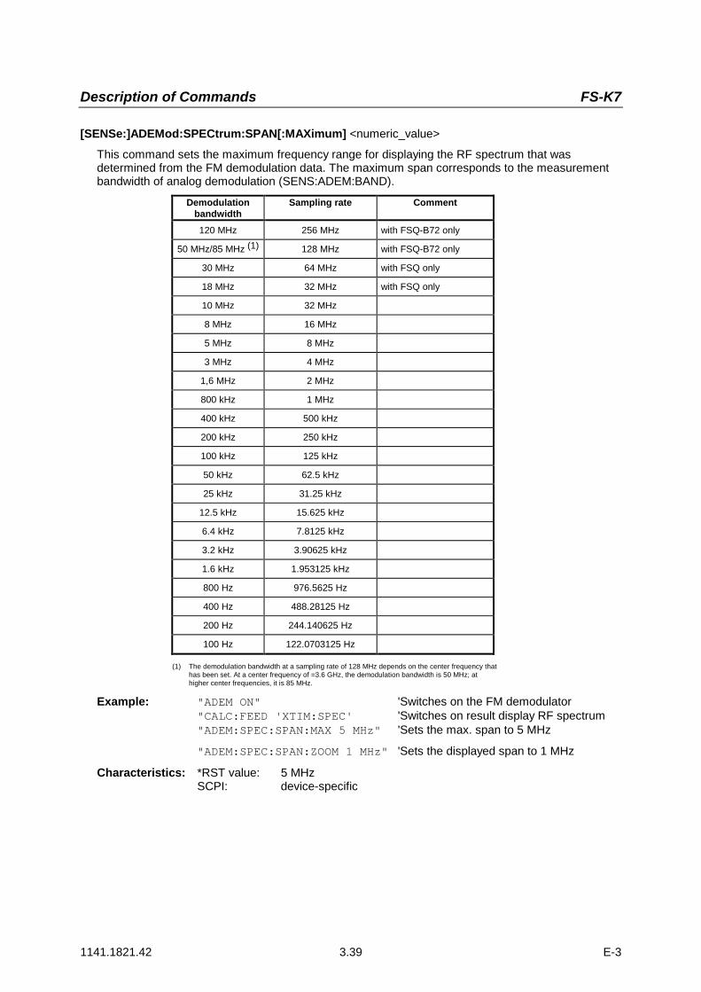
Description of Commands FS-K7
1141.1821.42 3.39 E-3
[SENSe:]ADEMod:SPECtrum:SPAN[:MAXimum] <numeric_value>
This command sets the maximum frequency range for displaying the RF spectrum that wasdetermined from the FM demodulation data. The maximum span corresponds to the measurementbandwidth of analog demodulation (SENS:ADEM:BAND).
Demodulationbandwidth
Sampling rate Comment
120 MHz 256 MHz with FSQ-B72 only
50 MHz/85 MHz (1) 128 MHz with FSQ-B72 only
30 MHz 64 MHz with FSQ only
18 MHz 32 MHz with FSQ only
10 MHz 32 MHz
8 MHz 16 MHz
5 MHz 8 MHz
3 MHz 4 MHz
1,6 MHz 2 MHz
800 kHz 1 MHz
400 kHz 500 kHz
200 kHz 250 kHz
100 kHz 125 kHz
50 kHz 62.5 kHz
25 kHz 31.25 kHz
12.5 kHz 15.625 kHz
6.4 kHz 7.8125 kHz
3.2 kHz 3.90625 kHz
1.6 kHz 1.953125 kHz
800 Hz 976.5625 Hz
400 Hz 488.28125 Hz
200 Hz 244.140625 Hz
100 Hz 122.0703125 Hz
(1) The demodulation bandwidth at a sampling rate of 128 MHz depends on the center frequency thathas been set. At a center frequency of =3.6 GHz, the demodulation bandwidth is 50 MHz; athigher center frequencies, it is 85 MHz.
Example: "ADEM ON" 'Switches on the FM demodulator"CALC:FEED 'XTIM:SPEC' 'Switches on result display RF spectrum"ADEM:SPEC:SPAN:MAX 5 MHz" 'Sets the max. span to 5 MHz
"ADEM:SPEC:SPAN:ZOOM 1 MHz" 'Sets the displayed span to 1 MHz
Characteristics: *RST value: 5 MHzSCPI: device-specific

Description of Commands FS-K7
1141.1821.42 3.40 E-3
[SENSe:]ADEMod:SPECtrum:SPAN:ZOOM <numeric_value>
This command sets the frequency range for result display of RF spectrum determined from FMdemodulation data. The frequency range for result display is limited to the maximum span(SENS:ADEM:SPEC:SPAN:MAX) or to the measurement bandwidth of analog demodulation(SENS:ADEM:BAND).
Example:"ADEM ON" 'Switches on the FM demodulator"CALC:FEED 'XTIM:SPEC' 'Switches on result display RF spectrum""ADEM:SPEC:SPAN:MAX 5 MHz" 'Sets the maximum span to 5 MHz"ADEM:SPEC:SPAN:ZOOM 1 MHz" 'Sets displayed span to 1 MHz
Characteristics: *RST value: 5 MHzSCPI: device-specific
[SENSe:]ADEMod:SPECtrum[:TYPE] <result type 1>,<result type 2>,<result type 3>
This command selects the result types to be created in parallel by the RF SPECtrum measurementwith active analog demodulation.
Parameters: <result type 1/2/3>.: WRITe The current measurement results will be obtained
AVERage The measurement results will be averaged over thegiven # of measurements
MAXHold The maximum result values will be obtained over thegiven # of measurements
MINHold The minimum result values will be obtained over thegiven # of measurements
VIEW The measurement results are frozen and displayed,i.e. they are not calculated for subsequentmeasurements.
OFF The result type will not be used.
Notes:Each value besides OFF can only be assigned to one result type at a time.Together with other signals, a maximum of six traces can be activated simultaneously. Forexample, three FM and three PM result types can be activated simultaneously.If all result types are set to OFF, switch off calculation of the AF spectrum
Examples: ADEM:SPEC AVER,MAXH,MINH 'Creates average, max hold and min hold'values at a time
ADEM:SPEC WRIT,OFF,OFF 'Only creates the current measurement valuesADEM:SPEC OFF,OFF,OFF 'Switches FM demodulation off
Characteristics: *RST values: OFF,OFF,OFFSCPI: device-specific

Description of Commands FS-K7
1141.1821.42 3.41 E-3
[SENSe:]ADEMod:SPECtrum:RESult? <result type>
This command reads the result data obtained by RF SPECtrum measurement depending on the typeindicated as a parameter. The data format of the output data block is defined by the FORMatcommand.
Note: It is not possible to read out trace data when result type VIEW is selected.
Parameters: <result type>: WRITe The current measurement results will be obtained
AVERage The measurement results will be averaged over thegiven # of measurements
MAXHold The maximum result values will be obtained over thegiven # of measurements
MINHold The minimum result values will be obtained over thegiven # of measurements
Notes:The result type indicated must be one of those configured by [SENSe:]ADEMod:SPEC[:TYPE].Otherwise a query error will be generated.
Return Values:
ASCII Format (FORMat ASCII):In this case the command will yield a list of comma separated values (CSV) of the measuredvalues in floating point format. The output unit is dBm.
Binary Format (FORMat REAL,32):In this case the command will yield binary data (Definite Length Block Data according to IEEE488.2), each measurement value being formatted in 32 Bit IEEE 754 Floating-Point-Format.The schematics of the result string will be as follows:#41024<value1><value2>...<value n>with#4 number of digits (= 4 in the example) of the following number of data bytes
1024 number of following data bytes (= 1024 in the example)
<value x> 4-Byte-Floating Point Value
Examples: ADEM:SET 8MHz,32000,EXT,POS,-500,30 'Sets up demodulator parametersADEM:SPEC AVER,MAXH,MINH 'Sets up RF spectrum results
'to measureADEM:SPEC WRIT,OFF,OFF 'Sets up AM results to measureADEM ON 'Switches on demodulatorINIT;*WAI 'Starts measurement and waits
'for syncFORM ASC 'Selects output formatADEM:SPEC:RES? AVER 'Reads RF spectrum average
'resultsADEM:SPEC:RES? MAXH 'Reads RF spectrum max hold
'resultsADEM:SPEC:RES? MINH 'Reads RF spectrum min hold
'resultsADEM:SPEC:RES? WRIT 'Reads spectrum current results
Characteristics: *RST values: -SCPI: device-specific

Description of Commands FS-K7
1141.1821.42 3.42 E-3
SENSe:BANDwidth SubsystemThis subsystem controls the setting of the analyzer’s filter bandwidths. Both groups of commands(BANDwidth and BWIDth) perform the same functions.
COMMAND PARAMETERS UNIT COMMENT [SENSe<1|2>] :BANDwidth
[:RESolution]:AUTO
:DEMod:BWIDth
[:RESolution]:AUTO
:DEMod
<numeric_value><Boolean><numeric_value>
<numeric_value><Boolean><numeric_value>
HZ--HZ
HZ--HZ
r
[SENSe<1|2>:]BANDwidth|BWIDth[:RESolution] <numeric_value>
This command sets the IF bandwidth of the demodulator.Analog resolution filters are available that are implemented as LC filters with four circuits (FSP) or 5circuits (FSU/FSQ).
Instrument IF bandwidth StepsFSP 300 kHz to 10 MHz 1,3,10
FSU 200 kHz to 10 MHz 1,2,3,5,10
FSQ 200 kHz to 50 MHz 1,2,3,5,10
If the resolution bandwidth is modified, coupling to the demodulation bandwidth is automaticallyswitched off.Example: "BAND 1MHz" Set IF bandwidth to 1 MHzCharacteristics: *RST value: - (AUTO is set to ON)
SCPI: conforming
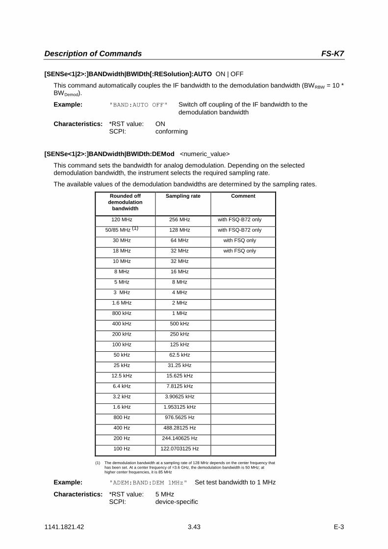
Description of Commands FS-K7
1141.1821.42 3.43 E-3
[SENSe<1|2>:]BANDwidth|BWIDth[:RESolution]:AUTO ON | OFF
This command automatically couples the IF bandwidth to the demodulation bandwidth (BWRBW = 10 *BWDemod).
Example: "BAND:AUTO OFF" Switch off coupling of the IF bandwidth to thedemodulation bandwidth
Characteristics: *RST value: ONSCPI: conforming
[SENSe<1|2>:]BANDwidth|BWIDth:DEMod <numeric_value>
This command sets the bandwidth for analog demodulation. Depending on the selecteddemodulation bandwidth, the instrument selects the required sampling rate.
The available values of the demodulation bandwidths are determined by the sampling rates.
Rounded offdemodulation
bandwidth
Sampling rate Comment
120 MHz 256 MHz with FSQ-B72 only
50/85 MHz (1) 128 MHz with FSQ-B72 only
30 MHz 64 MHz with FSQ only
18 MHz 32 MHz with FSQ only
10 MHz 32 MHz
8 MHz 16 MHz
5 MHz 8 MHz
3 MHz 4 MHz
1.6 MHz 2 MHz
800 kHz 1 MHz
400 kHz 500 kHz
200 kHz 250 kHz
100 kHz 125 kHz
50 kHz 62.5 kHz
25 kHz 31.25 kHz
12.5 kHz 15.625 kHz
6.4 kHz 7.8125 kHz
3.2 kHz 3.90625 kHz
1.6 kHz 1.953125 kHz
800 Hz 976.5625 Hz
400 Hz 488.28125 Hz
200 Hz 244.140625 Hz
100 Hz 122.0703125 Hz
(1) The demodulation bandwidth at a sampling rate of 128 MHz depends on the center frequency thathas been set. At a center frequency of =3.6 GHz, the demodulation bandwidth is 50 MHz; athigher center frequencies, it is 85 MHz
Example: "ADEM:BAND:DEM 1MHz" Set test bandwidth to 1 MHz
Characteristics: *RST value: 5 MHzSCPI: device-specific

Description of Commands FS-K7
1141.1821.42 3.44 E-3
TRACe Subsystem
The TRACe subsystem controls access to the instrument's internal trace memory.
COMMAND PARAMETERS UNIT COMMENT TRACe<1|2>
[:DATA] TRACE1|TRACE2|TRACE3|TRACE4,<block>|<numeric_value>...
-
TRACe<1|2>[:DATA] TRACE1| TRACE2| TRACE3, <block> | <numeric_value>
This command transfers trace data from the control computer to the instrument, the query readstrace data out of the instrument.
Note:With active FM Demodulator (option FS-K7), only the trace data that are displayed are read out andreloaded. Part of the measured data that can be queried with the marker, however, is derived fromthe raw data. These measurement results are no longer available after reloading a trace, the querycommands cause a query error.
Example: "TRAC TRACE1,"+A$ (A$: Data list in current format)"TRAC2? TRACE1"
Return values:Scaling of the data is in the currently set level unit.
ASCII format (FORMat ASCII):In this case, the command will return a list of comma separated values (CSV) of the measuredvalues.
The number of test points is 501 (FSP) or 625 (FSU/FSQ).
Binary format (FORMat REAL,32):In this case, the command returns binary data (Definite Length Block Data according to IEEE 488.2),with the measured values arranged in subsequent lists of I and Q data in 32-bit IEEE 754 floatingpoint format. The response string will have the following structure:
FSP: #42004<meas value 1><meas value value2>...<meas value 501>
FSU/FSQ: #42500<meas value 1><meas value value2>...<meas value 625>
with
#4 Number of digits in the following number of data bytes (= 4 in the example)
2004/2005 Number of the following data bytes (# of DataBytes, = 2004/2005 in the example)
<meas value x> 4-byte floating point value
Characteristics: *RST value: -SCPI: conforming
The trace data is transferred in the current format (corresponding to the command FORMatASCii|REAL). The device-internal trace memory is addressed using the trace names 'TRACE1' to'TRACE3'.
The transfer of trace data from the control computer to the instrument takes place by indicating thetrace name and then the data to be transferred. In ASCII format, this data consists of valuesseparated by commas. If the transfer takes place using the REAL format (REAL,32), the data istransferred in block format.

Description of Commands FS-K7
1141.1821.42 3.45 E-3
The parameter of the query is the trace name TRACE1 to TRACE3, it indicates which trace memorywill be read out.
Saving and recalling trace data together with the device settings to/from the device-internal hard diskor to/from a floppy is controlled via the commands "MMEMory:STORe:STATe" and"MMEMory:LOAD:STATe", respectively. Trace data is selected with"MMEMory:SELect[:ITEM]:ALL" or ""MMEMory:SELect[:ITEM]:TRACe". Trace data inASCII format (ASCCII FILE EXPORT) is exported with the command "MMEM:STORe:TRACe".
The transfer format for the trace data depends on the instrument setting:501 (FSP) or 625 (FSU and FSQ) results are output in the unit selected for display.
Note: With AUTO PEAK detector, only positive peak values can be read out.
FORMAT REAL,32 is to be used as format for binary transmission.
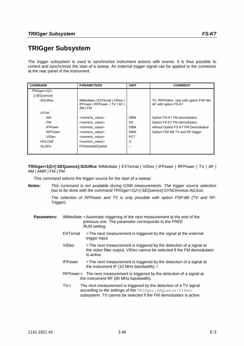
TRIGger Subsystem FS-K7
1141.1821.42 3.46 E-3
TRIGger Subsystem
The trigger subsystem is used to synchronize instrument actions with events. It is thus possible tocontrol and synchronize the start of a sweep. An external trigger signal can be applied to the connectorat the rear panel of the instrument.
COMMAND PARAMETERS UNIT COMMENT TRIGger<1|2>
[:SEQuence]:SOURce
:LEVel:AM:FM:IFPower:RFPower:VIDeo
:HOLDoff:SLOPe
IMMediate | EXTernal | VIDeo |IFPower | RFPower | TV | AF |AM | FM
<numeric_value><numeric_value><numeric_value><numeric_value><numeric_value><numeric_value>POSitive|NEGative
DBMHZDBMDBMPCTS--
TV, RFPOWer only with option FSP-B6AF with option FS-K7
Option FS-K7 FM demodulatorOption FS-K7 FM demodulatorwithout Option FS-K7 FM DemodulatorOption FSP-B6 TV and RF trigger
TRIGger<1|2>[:SEQuence]:SOURce IMMediate | EXTernal | VIDeo | IFPower | RFPower | TV | AF |AM | AMR | FM | PM
This command selects the trigger source for the start of a sweep:
Notes: This command is not available during GSM measurements. The trigger source selectionhas to be done with the command TRIGger<1|2>[:SEQuence]:SYNChronize:ADJust.
The selection of RFPower and TV is only possible with option FSP-B6 (TV and RF-Trigger).
Parameters: IMMediate =Automatic triggering of the next measurement at the end of theprevious one. The parameter corresponds to the FREE RUN setting.
EXTernal =The next measurement is triggered by the signal at the externaltrigger input
VIDeo =The next measurement is triggered by the detection of a signal atthe video filter output. VIDeo cannot be selected if the FM demodulatoris active.
IFPower =The next measurement is triggered by the detection of a signal atthe instrument IF (10 MHz bandwidth). I
RFPower= The next measurement is triggered by the detection of a signal atthe instrument RF (80 MHz bandwidth).
TV= The next measurement is triggered by the detection of a TV signalaccording to the settings of the TRIGger:SEQuence:VIDeo-subsystem. TV cannot be selected if the FM demodulator is active.

Description of Commands FS-K7
1141.1821.42 3.47 E-3
AF = The next measurement is triggered on detection of an FMFM modulated signal (equivalent to 'FM')
AMR = The next measurement is triggered on detection of anaudio signal after AM demodulation
AM = The next measurement is triggered on detection of anRF signal in the time domain.
PM = The next measurement is triggered on detection of anaudio signal after PM demodulation
Note: For triggering with the AF, AM and FM trigger sources to besuccessful, the measurement time must cover at least 5 periods of theaudio signal.
Example: "TRIG:SOUR EXT" Select the external trigger input as source for the triggersignal
Characteristics: *RST value: IMMediateSCPI: conforming
TRIGger<1|2>[:SEQuence]:LEVel:AM[:ABSolute] -100...+30dBm
This command sets the level when AM modulated signals are used as trigger source.
Note: For triggering with the AF, AM and FM trigger sources to be successful, the measurementtime must cover at least 5 periods of the audio signal.
Example: "TRIG:LEV:AM -30 dBm" Set the AM trigger threshold to -30 dBm
Characteristics: *RST value: -20 dBmSCPI: device-specific
TRIGger<1|2>[:SEQuence]:LEVel:AF -10...+10MHzTRIGger<1|2>[:SEQuence]:LEVel:FM -10...+10MHz
This command sets the level when FM modulated signals are used as trigger source.
Example: "TRIG:LEV:AM 10 kHz" Set the FM trigger threshold to 10 kHz
Characteristics: *RST value: 0 HzSCPI: device-specific
TRIGger<1|2>[:SEQuence]:LEVel:PM -1000...+1000RAD
This command sets the phase when PM-modulated signals are used as a trigger source.
Note: For triggering with the AF, AM, AMR, PM and FM trigger sources to be successful, themeasurement time must cover at least five periods of the audio signal
Example: "TRIG:LEV:PM 1.2 RAD" Set the PM trigger threshold to 1.2 rad
Characteristics: *RST value: 0 RADSCPI: device-specific

TRIGger Subsystem FS-K7
1141.1821.42 3.48 E-3
TRIGger<1|2>[:SEQuence]:LEVel:IFPower -30...-10DBM
This command sets the level for the IF power trigger source.
Example: "TRIG:LEV:IFP –20DBM"
Characteristics: *RST value: -20 DBMSCPI: device-specific
TRIGger<1|2>[:SEQuence]:LEVel:RFPower -50...-10DBM
This command sets the level for the RF power trigger source.
Example: "TRIG:LEV:RFP –20DBM"
Characteristics: *RST value: -20 DBMSCPI: device-specific
This command is only available in conjunction with option TV and RF-Trigger FSP-B6.
TRIGger<1|2>[:SEQuence]:HOLDoff -100...+100s
This command defines the length of the trigger delay.
Example: "TRIG:HOLD 500us"
Characteristics: *RST value: 0sSCPI: conforming
TRIGger<1|2>[:SEQuence]:SLOPe POSitive|NEGative
This command selects the slope of the trigger signal. The selection of the trigger slope is valid for alltrigger signal sources.
Example: "TRIG:SLOP NEG"
Characteristics: *RST value: POSitiveSCPI: conforming

Description of Commands FS-K7
1141.1821.42 3.49 E-3
UNIT SubsystemThe UNIT subsystem defines the units of the parameters to be set and measurement results.
COMMAND PARAMETERS UNIT COMMENTUNIT
:ANGLe DEG | RAD
UNIT:ANGLe DEG | RAD
This command selects the unit for angles.
Example: "UNIT:ANGL DEG"
Characteristics: *RST value: RADSCPI: conforming

Table of Softkeys and Hotkeys FS-K7
1141.1821.42 3.50 E-3
Table of Softkeys and Hotkeys including Assignment of Remote-Control Commands
This chapter contains the assignment of the remote-control commands to those softkey menus thatdiffer from the base unit with regard to the FM demodulator option. The operating manual of the baseunit covers the assignment of the unchanged menus.
FM Demodulator Main Menu
FM DEMOD
FM DEMODON OFF
INST:SEL ADEMINST:NSEL 3
RESULTDISPLAY
---
FMCALC:FEED 'XTIM:FM'
RMCALC:FEED 'XTIM:PM'
AMCALC:FEED 'XTIM:AM:REL'
RF POWERCALC:FEED 'XTIM:RFP'
RFSPECTRUM
CALC:FEED 'XTIM:SPECTRUM'
AFSPECTRUM
CALC:FEED 'XTIM:FM:AFSP'CALC:FEED 'XTIM:PM:AFSP'CALC:FEED 'XTIM:AM:REL:AFSP'CALC:FEED 'XTIM:RFP:AFSP'
SELECTTRACE
---
DIAGRAMFULL SIZE
DISP:WIND:SIZE LARG
RANGE---
DEVIATIONPER DIV
DISP:WIND:TRAC:Y:PDIV 50kHz
REFERENCEPOSITION
DISP:WIND:TRAC:Y:RPOS 50PCT
REFERENCEVALUE
DISP:WIND:TRAC:Y:RVAL 0HZ
AF COUPAC DC
SENS:ADEM:AF:COUP DC
ZERO PHASEREF POS
SENS:ADEM:PM:RPO:X 10us
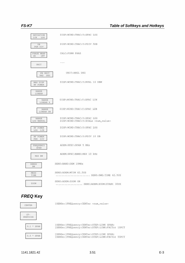
FS-K7 Table of Softkeys and Hotkeys
1141.1821.42 3.51 E-3
DEVIATIONLIN LOG
DISP:WIND:TRAC:Y:SPAC LOG
DBPER DIV
DISP:WIND:TRAC:Y:PDIV 5DB
PHASE WRAPON OFF
CALC:FORM PHAS
UNIT---
PM UNITRAD DEG
UNIT:ANGL DEG
MAX DISPRF POWER
DISP:WIND:TRAC:Y:RVAL 10 DBM
RANGELINEAR
RANGELINEAR %
DISP:WIND:TRAC:Y:SPAC LIN
RANGELINEAR DB
DISP:WIND:TRAC:Y:SPAC LDB
RANGELOG MANUAL
DISP:WIND:TRAC:Y:SPAC LOGDISP:WIND:TRAC:Y:SCALe <num_value>
RF POWERLOG LIN
DISP:WIND:TRAC:Y:SPAC LOG
RF POWERPER DIV
DISP:WIND:TRAC:Y:PDIV 10 DB
FREQUENCYSPAN
ADEM:SPEC:SPAN 5 MHz
RES BWADEM:SPEC:BAND:RES 10 kHz
DEMODBW
SENS:BAND:DEM 10MHz
MEASTIME
SENS:ADEM:MTIM 62.5US....................... SENS:SWE:TIME 62.5US
ZOOMSENS:ADEM:ZOOM ON.................. SENS:ADEM:ZOOM:STARt 30US
FREQ Key
CENTER[SENSe:]FREQuency:CENTer <num_value>
CF-SREPSIZE
0.1 * SPAN[SENSe:]FREQuency:CENTer:STEP:LINK SPAN;[SENSe:]FREQuency:CENTer:STEP:LINK:FACTor 10PCT
0.5 * SPAN[SENSe:]FREQuency:CENTer:STEP:LINK SPAN;[SENSe:]FREQuency:CENTer:STEP:LINK:FACTor 50PCT
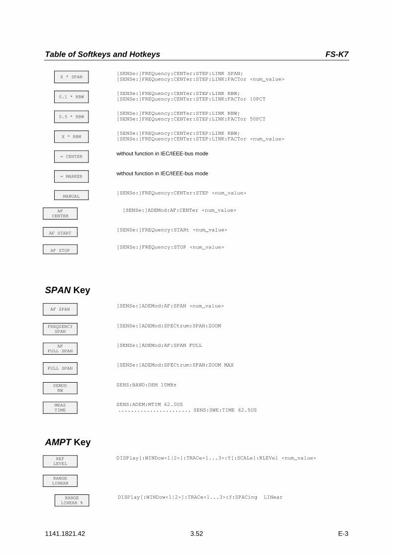
Table of Softkeys and Hotkeys FS-K7
1141.1821.42 3.52 E-3
X * SPAN[SENSe:]FREQuency:CENTer:STEP:LINK SPAN;[SENSe:]FREQuency:CENTer:STEP:LINK:FACTor <num_value>
0.1 * RBW[SENSe:]FREQuency:CENTer:STEP:LINK RBW;[SENSe:]FREQuency:CENTer:STEP:LINK:FACTor 10PCT
0.5 * RBW[SENSe:]FREQuency:CENTer:STEP:LINK RBW;[SENSe:]FREQuency:CENTer:STEP:LINK:FACTor 50PCT
X * RBW[SENSe:]FREQuency:CENTer:STEP:LINK RBW;[SENSe:]FREQuency:CENTer:STEP:LINK:FACTor <num_value>
= CENTERwithout function in IEC/IEEE-bus mode
= MARKERwithout function in IEC/IEEE-bus mode
MANUAL[SENSe:]FREQuency:CENTer:STEP <num_value>
AFCENTER
[SENSe:]ADEMod:AF:CENTer <num_value>
AF START[SENSe:]FREQuency:STARt <num_value>
AF STOP[SENSe:]FREQuency:STOP <num_value>
SPAN Key
AF SPAN[SENSe:]ADEMod:AF:SPAN <num_value>
FREQUENCYSPAN
[SENSe:]ADEMod:SPECtrum:SPAN:ZOOM
AFFULL SPAN
[SENSe:]ADEMod:AF:SPAN FULL
FULL SPAN[SENSe:]ADEMod:SPECtrum:SPAN:ZOOM MAX
DEMODBW
SENS:BAND:DEM 10MHz
MEASTIME
SENS:ADEM:MTIM 62.5US....................... SENS:SWE:TIME 62.5US
AMPT KeyREF
LEVELDISPlay[:WINDow<1|2>]:TRACe<1...3>:Y[:SCALe]:RLEVel <num_value>
RANGELINEAR
RANGELINEAR %
DISPlay[:WINDow<1|2>]:TRACe<1...3>:Y:SPACing LINear

FS-K7 Table of Softkeys and Hotkeys
1141.1821.42 3.53 E-3
RANGELINEAR DB
DISPlay[:WINDow<1|2>]:TRACe<1...3>:Y:SPACing LDB
RANGELOG 100 dB
DISPlay[:WINDow<1|2>]:TRACe<1...3>:Y:SPACing LOGarithmic;DISPlay[:WINDow<1|2>]:TRACe<1...3>:Y[:SCALe] 100 dB
RANGELOG MANUAL
DISPlay[:WINDow<1|2>]:TRACe<1...3>:Y:SPACing LOGarithmic;DISPlay[:WINDow<1|2>]:TRACe<1...3>:Y[:SCALe] <num_value>
RF ATTENMANUAL
INPut:ATTenuation <num_value>
RF ATTENAUTO
INPut:ATTenuation:AUTO ON
REF LEVELPOSITION
DISPlay[:WINDow<1|2>]:TRACe<1...3>:Y[:SCALe]:RPOSition <num_value>
REF LEVELOFFSET
DISPlay[:WINDow<1|2>]:TRACe<1...3>:Y[:SCALe]:RLEVel:OFFSet <num_value>
EL ATTENAUTO
INPut:EATT:AUTO ON (only with option FSP-B25)
EL ATTENMANUAL
INPut:EATT <num_value> (only with option FSP-B25)
EL ATTENOFF
INPut:EATT:STATe OFF (only with option FSP-B25)
RF INPUT50Ω 75Ω
INPut:IMPedance 50 | 75
BW Key
RES BWADEM:SPEC:BAND:RES 10 kHz
IF BWAUTO
BAND:RES:AUTO ON
IF BWMANUAL
BAND:RES 1 MHz
DEMODBW
SENS:BAND:DEM 10MHz
MEASTIME
SENS:ADEM:MTIM 62.5US....................... SENS:SWE:TIME 62.5US

Table of Softkeys and Hotkeys FS-K7
1141.1821.42 3.54 E-3
TRIG Key
FREE RUNTRIG:SOUR IMM
DEMODSIGNAL
---
FMSIGNAL
TRIG:SOUR FMTRIG:LEV:FM 10 kHz
RMSIGNAL
TRIG:SOUR PMTRIG:LEV:PM –1 rad
AMSIGNAL
TRIG:SOUR AMRTRIG:LEV:AM:REL 30 PCT
RF POWERSIGNAL
TRIG:SOUR AMTRIG:LEV:AM:ABS –30 dBm
EXTERNTRIG:SOUR EXTSWE:EGAT:SOUR EXT
IF POWERTRIG:SOUR IFPTRIG:LEV:IFP –20 dBm
RF POWERTRIG:SOUR RFPTRIG:LEV:RFP –40 dBm
TRIGGEROFFSET
TRIG:HOLD 10US
POLARITYPOS NEG
TRIG:SLOP POS
MKR KeyMARKER1..4
CALCulate<1|2>:MARKer<1...4>[:STATe] ON | OFF;CALCulate<1|2>:MARKer<1...4>:X <numeric value>;CALCulate<1|2>:MARKer<1...4>:Y?CALCulate<1|2>:DELTamarker1[:STATe] ON | OFF;CALCulate<1|2>:DELTamarker<1...4>:X <numeric value>;CALCulate<1|2>:DELTamarker<1...4>:Y?
MARKERNORM DELTA
CALCulate<1|2>:DELTamarker<1...4>[:STATe] ON | OFF;
ALL MARKEROFF
CALCulate<1|2>:MARKer<1...4>:AOFFCALCulate<1|2>:DELTamarker<1...4>:AOFF
MKR KeySELECTMARKER
without function in IEC/IEEE-bus mode
PEAKCALCulate<1|2>:MARKer<1...4>:MAXimum[:PEAK]CALCulate<1|2>:DELTamarker<1...4>:MAXimum[:PEAK]
REF LEVEL= MKR LVL
CALCulate<1|2>:MARKer<1...4>:FUNCtion:REFerence

FS-K7 Table of Softkeys and Hotkeys
1141.1821.42 3.55 E-3
NEXT PEAKCALCulate<1|2>:MARKer<1...4>:MAXimum:NEXTCALCulate<1|2>:DELTamarker<1...4>:MAXimum:NEXT
NEXTPEAK RIGHT
CALCulate<1|2>:MARKer<1...4>:MAXimum:RIGHtCALCulate<1|2>:DELTamarker<1...4>:MAXimum:RIGHt
NEXTPEAK LEFT
CALCulate<1|2>:MARKer<1...4>:MAXimum:LEFTCALCulate<1|2>:DELTamarker<1...4>:MAXimum:LEFT
MKR->TRACE
CALCulate<1|2>:MARKer<1...4>:TRACe <numeric value>CALCulate<1|2>:DELTamarker<1...4>:TRACe <numeric value>
MINCALCulate<1|2>:MARKer<1...4>:MINimum[:PEAK]CALCulate<1|2>:DELTamarker<1...4>:MINimum[:PEAK]
MIN NEXTCALCulate<1|2>:MARKer<1...4>:MINimum:NEXTCALCulate<1|2>:DELTamarker<1...4>:MINimum:NEXT
NEXTMIN RIGHT
CALCulate<1|2>:MARKer<1...4>:MINimum:RIGHtCALCulate<1|2>:DELTamarker<1...4>:MINimum:RIGHt
PEAKEXCURSION
CALCulate<1|2>:MARKer<1...4>:PEXCursion <num_value>
MKR FCTN KeySELECTMARKER
without function in IEC/IEEE-bus mode
PEAKCALCulate<1|2>:MARKer<1...4>:MAXimum[:PEAK]CALCulate<1|2>:DELTamarker<1...4>:MAXimum[:PEAK]
MKR->TRACE
CALCulate<1|2>:MARKer<1...4>:TRACe <numeric value>CALCulate<1|2>:DELTamarker<1...4>:TRACe <numeric value>


FS-K7 Index
1141.1821.12 4.1 E-3
4 Index
Note: The softkeys are listed alphebetically under the keyword "Softkey".
CCommand
description.................................................3.1
EExt Trig/Gate In input ...................................2.22
FFree-running Sweep.....................................2.21
HHotkey
SPECTRUM............................................3.12
IInput
Ext Trig/Gate In.......................................2.22
KKey
TRIG .......................................................2.21
OOffset
Trigger...................................................... 2.23
PPolarity
Trigger Slope ..........................................2.23
SSoftkey
AF CENTER............................................2.15AF COUP AC/DC....................................2.12AF FULL SPAN.......................................2.16AF POWER LOG/LIN..............................2.14AF SPAN.................................................2.16AF SPECTRUM ......................................2.10AF START...............................................2.15AF STOP.................................................2.15AM....................................................2.7, 2.22DB PER DIV............................................2.13DEVIATION LIN/LOG .............................2.13DEVIATION PER DIV .............................2.11EXTERN ........................................2.22, 3.47FM.............................................................2.6FM DEMOD...............................................2.1
FM DEMOD ON/OFF................................ 2.2FM SIGNAL .....................................2.21, 2.22FREE RUN .................................... 2.21, 3.47FREQUENCY SPAN .............................. 2.16FULL SIZE DIAGRAM ............................ 2.10FULL SPAN ............................................ 2.17HARDWARE INFO ................................... 3.1IF BW AUTO........................................... 2.19IF BW MANUAL...................................... 2.19IF POWER..................................... 2.22, 3.47IFPower .................................................. 3.49MARKER 1...4 ................................... 3.2, 3.5MAX DISP RF POWER .......................... 2.14PEAK EXCURSION.................................. 3.5PHASE WRAP ON/OFF ......................... 2.13PM ............................................................ 2.7PM UNIT RAD/DEG................................ 2.13POLARITY POS/NEG.................... 2.23, 3.49QP RBW UNCOUPLED ......................... 3.43RANGE ................................................... 2.11RANGE LIN % dB................................... 3.11RANGE LINEAR............................ 2.14, 3.11RANGE LINEAR %................................. 2.14RANGE LINEAR dB................................ 2.14RANGE LOG 100 dB.............................. 3.11RANGE LOG MANUAL ................. 2.14, 3.11REF LEVEL POSITION .......................... 3.10REFERENCE POSITION...........................2.11REFERENCE VALUE............................. 2.12RES BW.................................................. 2.19RESULT DISPLAY .. 2.5, 2.6, 2.8, 2.22, 2.23,................................................................ 3.47RF POWER PER DIV.................... 2.14, 2.22RFPower................................................. 3.49SELECT TRACE..................................... 2.10SPECTRUM.............................................. 2.9TRIGGER OFFSET ....................... 2.23, 3.49VIDEO..................................................... 3.47ZERO PHASE REF POS........................ 2.13
SoftkeyGRID MIN LEVEL ............................ 3.11Sweep
free-running ............................................ 2.21
TTrigger
extern...................................................... 2.22free-running ............................................ 2.21IF Power ................................................. 2.22Offset........................................................2.23RF Power....................................... 2.22, 2.23Slope....................................................... 2.23


