80
OPERATOR MANUAL GMDSS Marine Radio Decoder FMD25 FMD25 FMD 25 – 10/99

OPERATOR
MANUAL
GMDSS Marine Radio Decoder
FMD25
FMD25
FMD 25 – 10/99
FMD 25 – 10/99
ATTENTION
IMPORTANT INFORMATION
The FMD25 has two M5 threaded holes on either side for the supplied thumb screws, so that it can be fitted to the universal mounting bracket. The length of the thumb screws has been so determined, that, together with the bracket and the lock washers, they can only penetrate approx. 5mm into the thread.
Should you use alternative fitting methods or screws, please make sure that they do not penetrate the thread by more than 5mm.
By using longer screws, the integrated electronic could be damaged !!
FMD 25 – 10/99
Contents Page
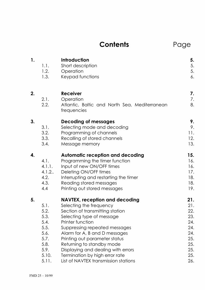
1. Introduction 5.1.1. Short description 5. 1.2. Operation 5. 1.3. Keypad functions 6.
2. Receiver 7.2.1. Operation 7. 2.2. Atlantic, Baltic and North Sea, Mediterranean
frequencies8.
3. Decoding of messages 9.3.1. Selecting mode and decoding 9. 3.2. Programming of channels 11. 3.3. Recalling of stored channels 12. 3.4. Message memory 13.
4. Automatic reception and decoding 15.4.1. Programming the timer function 16. 4.1.1. Input of new ON/OFF times 16. 4.1.2.. Deleting ON/OFF times 17. 4.2. Interrupting and restarting the timer 18. 4.3. Reading stored messages 18. 4.4 Printing out stored messages 19.
5. NAVTEX, reception and decoding 21.5.1. Selecting the frequency 21. 5.2. Section of transmitting station 22. 5.3. Selecting type of message 23. 5.4. Printer function 24. 5.5. Suppressing repeated messages 24. 5.6. Alarm for A, B and D messages 24. 5.7. Printing out parameter status 25. 5.8. Returning to standby mode 25. 5.9. Displaying and dealing with errors 25. 5.10. Termination by high error rate 25. 5.11. List of NAVTEX transmission stations 26.

FMD 25 – 10/99
6. Unoccupied
7. NMEA, printer and navigation log 30.7.1. Printing of NMEA data 30. 7.2. Activating log 31.
8. System (SET UP) 34.8.1. Setting of time and date 34. 8.2. Setting of owner’s and vessel’s name 35. 8.3. Printing out system data status 36. 8.4. Memory store deletion and reset 37.
9. Installation 38.9.1. Delivery contents 38. 9.2. Installation of unit 38.
Dimensions 40. Table and ceiling installation 41.
9.3. Power supply connection 42. 9.4. NMEA interface connection 43. 9.5. Antenna and earth connection 43.
Installation of long-wire antenna on back-stay 44. Installation of active antenna MD-AA 45. Installation of R+R active antenna 46.
9.6. Printer paper change 47. 9.7. Active antenna power supply 49. 9.8. LF audio out-put 49.
10. FMD25 Accessories 50.10.1. 24V DC/DC converter 50. 10.2. DC/DC converter installation 50. 10.3. DC936-DC/DC converter for 9-36V to 12V 51. 10.4. MD-AA - active antenna 52. 10.5. MLB – marine long-wire balun for back-stay 53. 10.6. F3A and F6A suppression filters 54. 10.7. M20-ALS – active loudspeaker for FMD25 55.
FMD 25 – 10/99
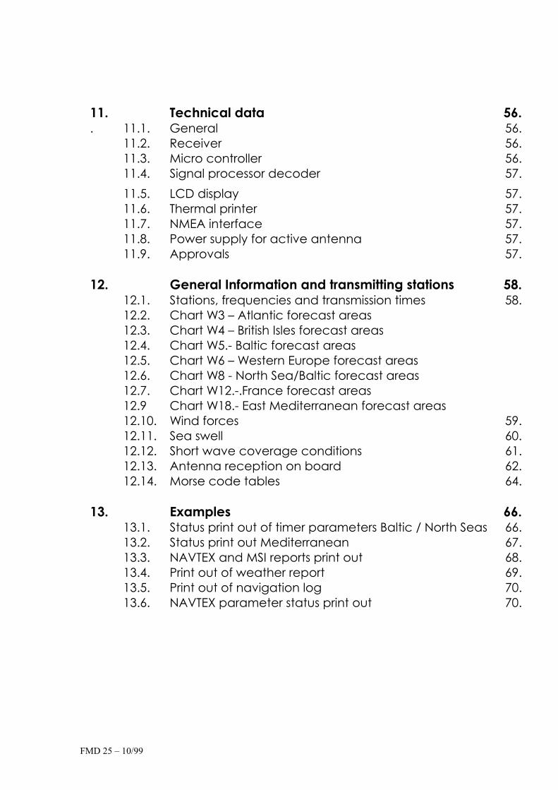
11. Technical data 56.. 11.1. General 56.
11.2. Receiver 56. 11.3. Micro controller 56. 11.4. Signal processor decoder 57.
11.5. LCD display 57. 11.6. Thermal printer 57. 11.7. NMEA interface 57. 11.8. Power supply for active antenna 57. 11.9. Approvals 57.
12. General Information and transmitting stations 58.12.1. Stations, frequencies and transmission times 58. 12.2. Chart W3 – Atlantic forecast areas 12.3. Chart W4 – British Isles forecast areas 12.4. Chart W5.- Baltic forecast areas 12.5. Chart W6 – Western Europe forecast areas 12.6. Chart W8 - North Sea/Baltic forecast areas 12.7. Chart W12.-.France forecast areas 12.9 Chart W18.- East Mediterranean forecast areas 12.10. Wind forces 59. 12.11. Sea swell 60. 12.12. Short wave coverage conditions 61. 12.13. Antenna reception on board 62. 12.14. Morse code tables 64.
13. Examples 66.13.1. Status print out of timer parameters Baltic / North Seas 66. 13.2. Status print out Mediterranean 67. 13.3. NAVTEX and MSI reports print out 68. 13.4. Print out of weather report 69. 13.5. Print out of navigation log 70. 13.6. NAVTEX parameter status print out 70.

FMD 25 – 10/99
14. Appendix 71.14.1. Service and Maintenance 71. 14.2. Service depots 71. 14.3. Warranties see extra pages 14.4. Software maintenance 72.
Software up-date enquiry form 73. 14.5 Error alarm 74. 14.5.1. “PRINTER ERROR” alarm 74. 14.5.2. Further acoustic alarms 75.

1. Introduction
1.1. Short Description
The Fastnet marine decoder contains the following functions:
a) Receiver a high quality receiver with the following important
features:Range : 8 pre-programmed channels
from 100 kHz to 13 MHz Modes : FSK and CWMemory stores : 8 frequencies with modes
b) NAVTEX receiver and decoder
Frequencies : 490.0 and 518.0 kHz
c) Morse, telex and SITOR Decoder By means of a PLL signal processor and an integrated microcomputer the following codes are automatically deciphered:
Morse code signs : 40 to 100 Bpm RTTY (radio teletype) : 50 Baud SITOR FEC : 100 Baud (NAVTEX)
d) NMEA printer and navigation log Print out of data via the NMEA interface. When connected to a GPS, a navigation log can be stored and printed out.
1.2. Operation
The back-lit, high contrast LCD display and an easy to use keypad, allow a user friendly operation of theFMD25. System information and stored decoded messages can be printed out by the integratedthermal printer on 80mm paper
FMD25 10/99
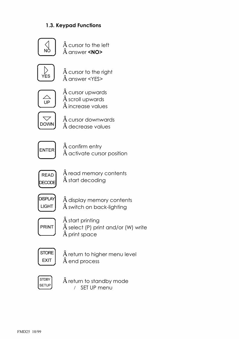
1.3. Keypad Functions
cursor to the left answer <NO>
cursor to the right answer <YES>
cursor upwards scroll upwardsincrease values
cursor downwards decrease values
confirm entryactivate cursor position
read memory contentsstart decoding
display memory contents switch on back-lighting
start printing select (P) print and/or (W) writeprint space
return to higher menu levelend process
return to standby mode SET UP menu
FMD25 10/99

FMD25 10/99
2. Receiver
2.1. Operation
The receiver requires practically no operation.
The NAVTEX frequencies (490.0 and 518.0 kHz) are pre-programmed.The choice between the two can be made in the NAVTEX menu (seechapter 5).
Further this model has 8 pre-programmed frequencies according to a defined sailing region.
The frequencies of a transmitting station are normally set down internationally and are rarely changed. However, each pre-programmed frequency has been allotted the following parameters:
Decoding mode MorseRTTYSITOR
The message decoding mode has not been laid down, as it is expected, that, in the next few years, various stations will change their transmission from Morse to RTTY or RTTY to SITOR-FEC respectively.On the following pages you can find a list of the present codes used.
It is not necessary to adjust the mode in the receiver. This is done automatically, when selecting the decoding mode.
FMD25 10/99

2.2. North-Atlantic, Baltic-, North and Mediterranean Seas frequencies
FMD20 EU -
channel frequency(kHz) code station
01 147.3 RTTY Pinneberg
02 4583.0 RTTY Pinneberg
03 7646.0 RTTY Pinneberg
04 10100.8 RTTY Pinneberg
05 11039.0 RTTY Pinneberg
06 8417.0 SITOR-FEC Portishead
07 4292.0 Morse Roma
08 8530.0 Morse Roma
FMD25 10/99

3. Decoding of messages
The FMD25 can store and decipher MORSE, RTTY and SITOR codes, whichthen can be read or printed out in plain language. In radio signal trafficthere are many other kinds of keyed codes. As they are not for use by the general public, they cannot be decoded by the FMD25.
Weather and navigational warnings for shipping are transmitted in one of the above mentioned codes, which can be decoded by the FMD25.
The received signal tone (LF) is fed to a PLL signal decoder, which filters out the audio signals and turns them into digital information. This in turn will beconverted into legible symbols by the integrated micro-processor.
The type of code used by the individual station, can be found in the appropriate manuals for marine radio stations. The codes used, vary:
for MORSE also : CW,A1,A1A, telegraphy for RTTY also : F1B, telexfor SITOR also : FEC,F1B
3.1. Selecting mode and decoding
In various manuals, the type of code used by a station is shown mostly as A1A, F1B etc. The following list is an overlook of types of transmissiongenerally used in marine radio transmission. The required adjustment to receiver and decoder are also listed
FMD25 10/99

Message Transmission Types
Transmission receiver decoderMode set up set up
A1A - Morse telegraphy with non-damped carriere.g. Roma, etc.
CWMorse
A2A - Morse telegraphy in double sideband
CW Morse
A3E - audio radio in double side band e.gBBC, DLF tc.
* *
F1B - FM telex signal from Pinneberg FSK RTTY
F1B - FM telex signal specially for NAVTEX FSK SITOR-NEC
F1B - FM telex (MSI frequenciese.g.Portishead: 4211 kHz (402)
FSK SITOR-FEC
F1C - FM telefax from Bracknell,Pinneberg etc.
* *
F3E - VHF Audio radio from 88 to 108 MHz *
*
H3E - AM audio radio, SSB with carrier e.g.Murmansk
* *
J3E - SSB audio radio* *
R3R - as H3E however with reducedcarrier e.g. Niton
* *
*- not available with FMD25
FMD25 10/99
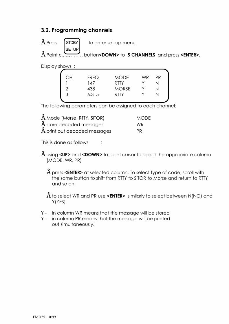
3.2. Programming channels
Press to enter set-up menu
Point cursor with button<DOWN> to 5 CHANNELS and press <ENTER>.
Display shows :
CH FREQ MODE WR PR1 147 RTTY Y N2 438 MORSE Y N3 6.315 RTTY Y N
The following parameters can be assigned to each channel:
Mode (Morse, RTTY, SITOR) MODEstore decoded messages WRprint out decoded messages PR
This is done as follows :
using <UP> and <DOWN> to point cursor to select the appropriate column (MODE, WR, PR)
press <ENTER> at selected column. To select type of code, scroll withthe same button to shift from RTTY to SITOR to Morse and return to RTTYand so on.
to select WR and PR use <ENTER> similarly to select between N(NO) and Y(YES)
Y - in column WR means that the message will be stored Y - in column PR means that the message will be printed out simultaneously.
FMD25 10/99

After checking that the parameters and the desired set up is correct,return to NAVTEX standby mode by pressing <EXIT> twice.
3.3. Recalling channels
to recall a channel press twice
the following picture appears on the display:
1 R 147 5 R 11.0892 R 4.583 6 S 8.4173 R 7.646 7 M 4.2924 R 10.100 8 M 8.530
1 ... 8 represent the channel number R / M / S represent RTTY/MORSE/SITORfollowed by the frequency in kHz
set the cursor to the requested channel by means of <UP> an <DOWN>
confirm by pressing <ENTER>
For instance, should you have chosen channel 5, the following picturewill be displayed :
_7.646kHz CH05
>>>RTTY 50 Bd
This means that the receiver is receiving on the 7646 kHz frequency. Thearrows show the strength of the reception signal. With six or more arrows,you can expect reasonable decoding. The bottom line shows that the code being used is RTTY (Radio Tele Type) at a transmission rate of 50Baud/m.
FMD25 10/99
After a short phase for the decoder to synchronise, the decoded text will appear on the top line.
According to the selected mode in 3.2., the decoded text can only be read in the display or stored in the memory and printed out.
The selection can be altered by pressing button <PRINT>. The followingfunctions for selection will appear on the bottom line:
_ _ display only P _ display and print simultaneously_ W display and store simultaneouslyP W display, store and print simultaneously.
This will not influence the mode selection in 3.2.
3.4. Message memory
The FMD25 possesses two separate independent memory stores. One for NAVTEX messages (see chap.5) and one for Morse, RTTY and SITOR-FEC messages.
The latter has a capacity of about 15000 characters. A message of maximum 3750 characters can be stored in a data record. Should a message be longer, further data records will be automatically opened.All in all, 100 data records can be filed with a total capacity of 15000 characters. Should the memory store be full, a new message will be stored by replacing the oldest messages. The most up-to-date messages will always be available whether decoded from Morse, RTTYor SITOR.
It can happen that a new message of only a few characters replaces the oldest message containing 3750 characters. At this moment the store contents have been reduced to 11250 characters.
FMD25 10/99
On completion of the message, every data record will be stored with a identification in form of date and time (DDMMhhmm). Further each data record will be given the information from which channel (CH) the message was received, this enables messages to be recalled chronologically.
Should the FMD25 be switched off during storage, whether deliberatelyor not (e.g. power interruption), the actual data record will not be stored because of lack of end of file identifier.
Because of strong disturbance (e.g. starting the motors with weak batteries), it can happen that the identification of data records may be partly or completely deleted. In this case, it may be possible to read messages only partly or not at all. On restarting the unit it can happen that all messages in the memory are deleted for safety reasons,because the unit cannot recognise the identifications.
Thereafter newly decoded messages will be stored correctly.
FMD25 10/99
4. Automatic Reception and Decoding
The FMD25 has a timer function for the storage of 9 programmes.Each storage contains a starting time, stop time and the channel number of a stored frequency (similar to that in a video recorder).The transmission times of weather messages can be found in the usual manuals but to be on the safe side it is recommended to addsome time before and after the start/stop times.
For reference the following transmission times can be used:
MORSE transmissions approx. 30 mins.RTTY transmissions approx. 15 mins.SITOR transmissions approx. 10 mins
The FMD25 will automatically switch to the required frequency at the selected start time and will decode according to the input parameters. The decoded message will be stored, according to the parameters, in the assigned channel if "W" was answered with <Y>. It will be directly printed out if "P" was answered with <Y>. (See chap. 8 - System parameter input).
On reaching the stop time, the FMD25 will switch back automatically into standby mode i.e. the basic mode for NAVTEX reception). Before programming the timer the assignment channels must be programmed. (See chap. 3.2.)
page 4-1 FMD25 10/99
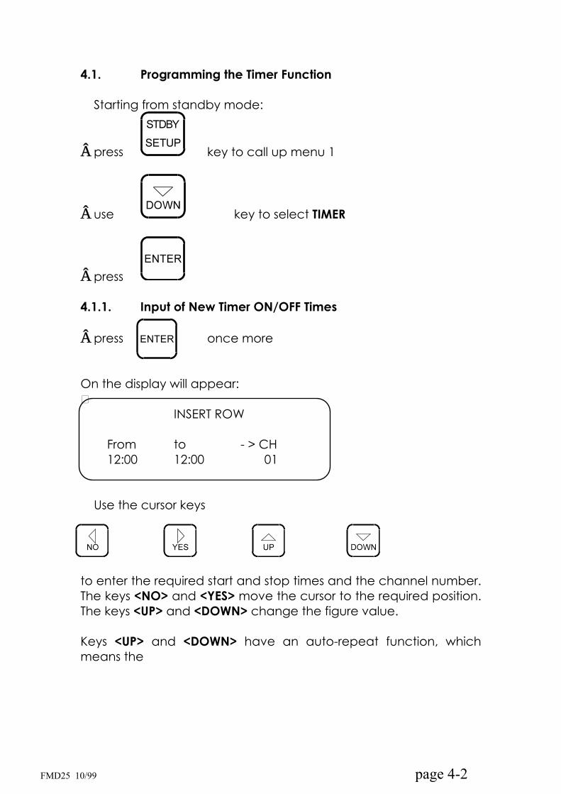
4.1. Programming the Timer Function
Starting from standby mode:
press key to call up menu 1
use key to select TIMER
press
4.1.1. Input of New Timer ON/OFF Times
press once more
On the display will appear:�
INSERT ROW
From to - > CH12:00 12:00 01
Use the cursor keys
page 4-2
to enter the required start and stop times and the channel number.The keys <NO> and <YES> move the cursor to the required position.The keys <UP> and <DOWN> change the figure value.
Keys <UP> and <DOWN> have an auto-repeat function, which means the
FMD25 10/99

selected value will increase or decrease in steps as long as the key is depressed. As long as you have not pressed <ENTER> you can change the value as often as required.Having checked that all values are correct press <ENTER>. By pressing <ENTER> once more you can enter further programme rows.
4.1.2. Deleting Timer ON/OFF Times
Call up TIMER menu as in 4.1.
page 4-3
Press key
On display will appear:�
DELETE ROW NO. : 1
Use the cursors <UP> and <DOWN> to select the number of the row to be deleted and activate by pressing <ENTER>. To leave the TIMER mode without a row deletion, press <EXIT>.
Press <EXIT> once more to return to the standby mode The maximum length of time in the timer function is 60 minutes.However it is possible to put in the same start time as the previousstop time. In the case where to programmed times overlap, the newer start time is dominant
Should a timer function be interrupted my manual operation e.g.calling up another frequency, the unit will still return to standby mode on reaching the stop time
FMD25 10/99

4.2. Interrupting and Restarting the Timer
An actual timer programme can be interrupted by pressing the <STDBY> key. The unit will switch back automatically to the standby mode at the respective stop time. It is possible to restart the unit during operation by switching it off for approx. 3 to 5 seconds.When switched on the unit returns to its programmed status.
4.3 Reading Stored Messages
Stored messages can be read on the display as often as desired.The complete data record store disposes of more than 20000 characters. Of this amount approx. 5500 are reserved for NAVTEX messages, the rest for Morse, RTTY and SITOR together. When the storage space is full, the oldest message will be automatically deleted. However this is done separately for NAVTEX and other messages. Meaning that the oldest NAVTEX message cannot be replaced by a new RTTY message, only by a new NAVTEX message and vice versa. Each message is identified by date and time in the following form: DD.MM.HH.MM (day, month, hour, minutes).
page 4-4
Press key to recall READ MEMORY
use keys and to select the type of
message to be read (NAVTEX or RD CH x) and press <ENTER>
press key once more
FMD25 10/99

The display will now show, when in NAVTEX, the list of messages with NAVTEX identification (e.g. JA34), and when in RD CH x, the list of frequencies.
In the latter case select the desired channel with the cursors <UP>and <DOWN> and press <ENTER>.
The display will show the stored messages by date and stop time in number sequence DD.MM.HH.MM (Day, month, hour minutes).
Place cursor on selected message.
page 4-5
press now the key and the message appears on the display.
keys <UP> and <DOWN> enable you to "turn the pages". On reaching the end of the message or by pressing <EXIT>,the read out will end.
by pressing <EXIT> once more you will return to standbymode.
4.4 Printing Out Stored Messages
Stored messages can be printed out as often as required.
Select the message to be printed out as READ MEMORY (see 4.3.)
press key to call up READ MEMORY
select message to be printed out
FMD25 10/99

page 4-6
by pressing key the message will be
printed out from start to finish.Printing can be stopped by pressing <EXIT>
It is possible to print only a part of the message e.g. only the sector applicable to your sailing region. This is done as follows:
press key<DISPLAY> and message appears on display.
"turn the pages" with the cursors <UP> and <DOWN>
by pressing <PRINT> the printer will commence from the displayed page
press <EXIT> when required or allow printing to continue until the message has ended
press <EXIT> twice to return to standby mode
FMD25 10/99

5. NAVTEX, Reception and Decoding
When the unit is in standby mode, it is automatically operating as a NAVTEX receiver and therefore a manual activation is not necessary
ATTENTION:
During the reception of other stations, also when receiving a message programmed to be stored by the timer, NAVTEX cannotbe received.
However, depending on your position, you should put in the necessary system parameters to enable the best possible NAVTEX information.
In put of the parameters is done as follows:
press key <SET UP> to call up set up menu
with cursor <DOWN> spring to position 4 - NAVTEX
press <ENTER> to enter NAVTEX menu
Display will show
1 FREQU. 5 REPEAT 2 STATION 6 ALARM 3 MESSAGE 7 STATUS 4 PRINT 8 EXIT
5.1 Selecting the Frequency
The FMD25 is programmed at present to receive two international NAVTEX frequencies:
518 kHz for coastal regions in English and
490 kHz for coastal regions in the local language
At present only NAVTEX stations using 518 kHz are active
FMD25 10/99

press <ENTER> to call up FREQUENCY menu use the cursors <UP> and <DOWN> to select the frequencies 490.00 kHz or 518.00 kHz. The frequency 518 kHz has been chosen as basic adjustment.Fine tuning is unnecessary, as the PLL decoder compensates frequency deviation.
press key to return to NAVTEX menu.
The frequency which appeared last on the display has been stored and is active in standby mode.
5.2. Selection of Transmitting Stations
With cursor <DOWN> to position 2 – STATION
press <ENTER>and the display will show:
STATIONS
ABCDEFGHIJKLMNOPQRSTUVWXYZ
NAVTEX stations are identified by the letters -A- to -Z-. Stations from which messages should be received are represented by capital letters, and stations from which messages should be suppressed with small letters.
use the cursors to select an individual letter
use the cursors to change the letters from capitals to small letters
FMD25 10/99
An up-to-date list of NAVTEX transmission stations (Spring 1995) can be found at the end of this chapter.
having checked that all adjustments are correct press
to return to NAVTEX menu. The selected adjustment will be stored.
5.3. Selecting Type of Message
Cursor on position -3- MESSAGE and pressSimilar to station selection , the messages are identified by letters and the selection of messages is analogue.
The international definition of the letters is
A = navigational warningsB = meteorological warningsC = ice reportsD = SAR informationE = meteorological prognosisF = pilot service messages G = DECCA messagesH = LORAN messagesI = OMEGA messagesJ = SATNAV messagesK = messages about other electronic navigational assistance L = additional navigational warnings V - Y = special services, tests Z = no message available
Messages of type -A-,-B- and-D- cannot be suppressed.
by pressing key selection will be stored and
return to NAVTEX menu.
FMD25 10/99

5.4. Printer Function
In NAVTEX <SET UP> cursor on PRINT and press key <ENTER>
You can select now whether you wish the message to be printed out while being received or, stored, to be printed out on desire, by answering with keys <YES> and <NO>.
by pressing key the selection will be stored and
it returns to NAVTEX menu.
5.5. Suppressing Repeated Messages
Current NAVTEX messages are transmitted repeatedly usually every 4 or 6 hours. A repeat message, which has already been stored and printed out, can be suppressed.
As before cursor on position 5 – REPEAT and enter.
Answer the question with <YES> or <NO> and
store with key
5.6. Alarm for A, B and D messages
Should the FMD25 receive messages of the type A, B or D they can be alerted with an acoustic alarm.
Cursor position 6 - ALARM and enter.
If you wish alarm activated for A, B and D type messages press <YES>
press to store and return to NAVTEX menu.
FMD25 10/99

5.7. Print out of parameter status
For your own control you can print out the input of the parameters
Cursor on position 7 and enter to print out STATUS
You will receive a simple and clear print out, making it easy to control, that all input parameters are correct.
5.8. Returning to standby mode
This can be done either by pressing the key twice or:
Cursor on position 8 and press <ENTER> to EXIT
The display will now show the standby mode.
5.9. Displaying and dealing with errors
The SITOR code used by NAVTEX can recognise errors. Every data field, to which a character has been assigned, will be repeated and have a relationship of 4:3 bit. Only when both data fields match and are validdoes the corresponding character appear as a capital letter. Should it be recognised as valid only once, then it will appear as a small letter. Ifboth assigned data field characters be non-valid, then it will appear as an * (asterisk). It is not common form of expression. We are of the opinion that a small letter holds more information than an asterisk *.
5.10. Termination by high error rate
When deciphering NAVTEX, the error rate of the decoded signal will be examined. Should the acceptance rate be exceeded, then the print out, if activated, will be interrupted and the message will be automatically deleted from the memory store.
FMD25 10/99
FMD25 10/99
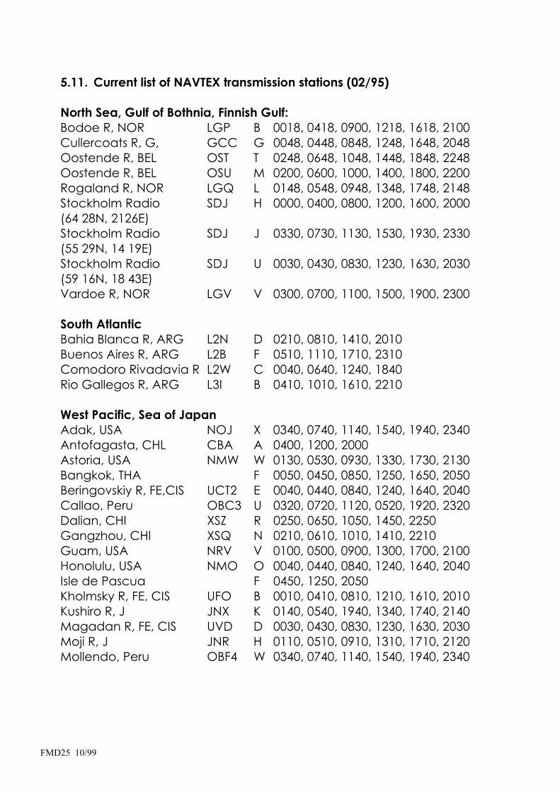
5.11. Current list of NAVTEX transmission stations (02/95)
North Sea, Gulf of Bothnia, Finnish Gulf: Bodoe R, NOR LGP B 0018, 0418, 0900, 1218, 1618, 2100 Cullercoats R, G, GCC G 0048, 0448, 0848, 1248, 1648, 2048 Oostende R, BEL OST T 0248, 0648, 1048, 1448, 1848, 2248 Oostende R, BEL OSU M 0200, 0600, 1000, 1400, 1800, 2200 Rogaland R, NOR LGQ L 0148, 0548, 0948, 1348, 1748, 2148 Stockholm Radio SDJ H 0000, 0400, 0800, 1200, 1600, 2000 (64 28N, 2126E) Stockholm Radio SDJ J 0330, 0730, 1130, 1530, 1930, 2330 (55 29N, 14 19E) Stockholm Radio SDJ U 0030, 0430, 0830, 1230, 1630, 2030 (59 16N, 18 43E) Vardoe R, NOR LGV V 0300, 0700, 1100, 1500, 1900, 2300
South Atlantic Bahia Blanca R, ARG L2N D 0210, 0810, 1410, 2010 Buenos Aires R, ARG L2B F 0510, 1110, 1710, 2310 Comodoro Rivadavia R L2W C 0040, 0640, 1240, 1840 Rio Gallegos R, ARG L3I B 0410, 1010, 1610, 2210
West Pacific, Sea of Japan Adak, USA NOJ X 0340, 0740, 1140, 1540, 1940, 2340 Antofagasta, CHL CBA A 0400, 1200, 2000 Astoria, USA NMW W 0130, 0530, 0930, 1330, 1730, 2130 Bangkok, THA F 0050, 0450, 0850, 1250, 1650, 2050 Beringovskiy R, FE,CIS UCT2 E 0040, 0440, 0840, 1240, 1640, 2040 Callao, Peru OBC3 U 0320, 0720, 1120, 0520, 1920, 2320 Dalian, CHI XSZ R 0250, 0650, 1050, 1450, 2250 Gangzhou, CHI XSQ N 0210, 0610, 1010, 1410, 2210 Guam, USA NRV V 0100, 0500, 0900, 1300, 1700, 2100 Honolulu, USA NMO O 0040, 0440, 0840, 1240, 1640, 2040 Isle de Pascua F 0450, 1250, 2050 Kholmsky R, FE, CIS UFO B 0010, 0410, 0810, 1210, 1610, 2010 Kushiro R, J JNX K 0140, 0540, 1940, 1340, 1740, 2140 Magadan R, FE, CIS UVD D 0030, 0430, 0830, 1230, 1630, 2030 Moji R, J JNR H 0110, 0510, 0910, 1310, 1710, 2120 Mollendo, Peru OBF4 W 0340, 0740, 1140, 1540, 1940, 2340

FMD25 10/99
Naha R, J JNB G 0100, 0500, 0900, 1300, 1700, 2100 Otaru R, J JNL J 0130, 0530, 0930, 1330, 1730, 2130 Paita, Peru OBY S 0300, 0700, 1100, 1500, 1900, 2300 Petropavlovsk-K R, FE UBE4 C 0020, 0420, 0820, 1220, 1620, 2020 Prince Rupert, CAN VAJ D 0030, 0430, 0930, 1230, 1630, 2030 Provideniya R, FE, CIS UPB F 0050, 0450, 0850, 1250, 1650, 2050 Puerto Montt, CHL CBP D 0430, 1230, 2030 Punta Arenas, CHL CBM E 0440, 1240, 2040 San Francisco, USA NMC C 0400, 0800, 1200, 1600, 2000, 2400 Singapore, Jurong 9VG C 0020, 0420, 0820, 1220, 1420, 2020 Shanghai, CHI XSG Q 0240, 0640, 1040, 1440, 2240 Talcahuano, CHL CBT C 0420, 1220, 2020 Tofino, CAN VAE H 0110, 0510, 0910, 1310, 1710, 2110 Vladivostok R, SE, CIS UIK A 0000, 0400, 0800, 1200, 1600, 2000 Yokohama R, J JGC I 0120, 0520, 0920, 1320, 1720, 2120 Kodiak, ALS, USA NOJ J 0300, 0700, 1100, 1500, 1900, 2300 Long Beach, Cambria NMQ9 Q 0045, 0445, 0845, 1245, 1645, 2045 Valparaiso R, CHL CBV B 0410, 1210, 2010
Indian Ocean, Gulf of Arabia, Red Sea Ambon, IN B 0010, 0410, 0810, 1210, 1610, 2010 Bombay R, IND VWB G 0100, 0500, 0900, 1300, 1700, 2100 Damman R, ARS HZG G 0005, 0605, 1205, 1805 Hong Kong VRX L 0150, 0550, 0950, 1350, 1750, 2150 Jakarta, IN PKX E 0040, 0440, 0840, 1240, 1640, 2040 Jayapura, IN PNK A 0000, 0400, 0800, 1200, 1600, 2000 Madras R, IND VWM P 0230, 0630, 1030, 1430, 1830, 2230 Makkasar, IN D 0030, 0430, 0830, 1230, 1630, 2030 Muscat, Oman A4M M 0200, 0600, 1000, 1400, 1800, 1905 Hamala R, BHR A9M B 0010, 0410, 1810, 1210, 1610, 2010 Serapeum R, EGY SUZ N 0750,1150,1550,1950
Mediterranean Sea, Black Sea Alexandria SUH N 0610, 1010, 1410, 1810 Antalya R, TUR TAL F 0050, 0450, 0850, 1250, 1650, 2050 Augusta IQA S 0300, 0700, 1100, 1500, 1900, 2300 Bari IPB U 0320, 0720, 1120, 1520, 1920, 2320 Cagliari IDC T 0310, 0710, 1110, 1510, 1910, 2310 Cape Town ZSC C 0020, 0420, 0820, 1220, 1620, 2020 Cross Corsen, F A 0000, 0400, 0800, 1200, 1600, 2000

FMD25 10/99
Cross La Garde (Toulon) W 0340, 0740, 1140, 1540, 1940, 2340 Durban ZSD O 0220, 0620, 1020, 1420, 1820, 2220 Iraklion R, GRC SVH H 0110, 0510, 1910, 1310, 1710, 2110 Ismailia (Serapeum) X 0750, 1150, 1550, 1950 Israel, Haifa P 0230, 0630, 1030, 1430, 1830, 2230 Istanbul R, TUR TAH D 0030, 0430, 0830, 1230, 1630, 2030 Izmir R, TUR TAN I 0120, 0520, 0920, 1320, 1720, 2120 Kerkyra R, GRC SVK K 0140, 0540, 0940, 1340, 1740, 2140 Limnos R, GRC SVL L 0150, 0550, 0950, 1350, 1750, 2150 Malta, 9HD O 0220, 0620, 1020, 1420, 1820, 2220 Mariupol R, UK, CIS USU B 0100, 0500, 0900, 1300, 1700, 2300 Odessa R, UK, CIS UTW C 0230, 0630, 1030, 1430, 1830, 2230 Port Elizabeth ZSQ I 0120, 0620, 1020, 1420, 1820, 2220 Roma, I, IAR R 0250, 0650, 1050, 1450, 1850, 2250 Samsun R, TUR TAF E 0040, 0440, 0840, 1240, 1640, 2040 Split R, CRT 9AS Q 0250, 0650, 1050, 1450, 1850, 2250 Tarifa, ESP EAC G 0100, 0500, 0900, 1300, 1700, 2100 Troodos R, CYP 5BA M 0200, 0600, 1000, 1400, 1800, 2200 Varna R, BUL LZW J 0130, 0530, 0930, 1330, 1730, 2130
Atlantic, Bering Sea, English Channel, Norwegian Sea Arkhangelsk R, RU, CIS UGE F 0200, 0600, 1000, 1400, 1800, 2200 Bermuda ZBM B 0010, 0410, 0810, 1210, 1610, 2010 Boston, USA NMF F 0445, 0845, 1245, 1645, 2045, 0045 Horta, AZR CTH F 0050, 0450, 0850, 1250, 1650, 2050 Ijmuiden Coastguard, NLPBK P 0348, 0748, 1148, 1548, 1948, 2348 Labrador, CAN VOK X 0350, 0750, 1150, 1550, 1950, 2350 La Coruna ( NW Spain ) EAF D 0030, 0430, 0830, 1230, 1630, 2030 Las Palmas ( Canary I. ) EAL I 0120, 0520, 0920, 1320, 1720, 2120 Lisbon, POR CTV R 0250, 0650, 1050, 1450, 1850, 2250 Miami, USA NCF A 0000, 0400, 0800, 1200, 1600, 2000 Montreal, CAN VFN X 0340, 0740, 1140, 1540, 1940, 2340 Murmansk R, RU, CIS UMN C 0120, 0520, 0920, 1220, 1720, 2120 New Orleans, USA NMG G 0300, 0700, 1100, 1500, 1900, 2300 Niton R, G GNI S 0018, 1418, 0818, 1218, 1618, 2018 Portpatrik R, G GPK O 0130, 0530, 0930, 1330, 1730, 2130 Portsmouth, USA NMN N 0130, 0530, 0930, 1330, 1730, 2130 Reykjavik R, ISL TFA R 0318, 0718, 1118, 1518, 1918, 2318

FMD25 10/99
San Juan,Puerto Rico,USANMR R 0200, 0600, 1000, 1400, 1800, 2200 Sept Isles, CAN VCK C 0020, 0420, 0820, 1220, 1620, 2020 St. Johns, CAN VON O 0220, 0620, 1020, 1420, 1820, 2220 Sydney, NS, CAN VCO Q 0240, 0640, 1040, 1440, 1840, 2240 Tarifa ( Gibraltar ) EAC G 0100, 0500, 0900, 1300, 1700, 2100 Thunder Bay, CAN VBA P 0230, 0630, 1030, 1430, 1830, 2230 Wiarton, CAN VBC H 0110, 0510, 0910, 1310, 1710, 2110 Yarmouth, CAN VAU U 0320, 0720, 1120, 1520, 1920, 2320
7. NMEA Printer and Navigation Log
7.1. Printing of NMEA Data
The FMD25 can be used as an NMEA printer. In this mode NMEAsignals are fed via the NMEA 0183 interface unaltered to the integrated or external printer.
Please note, that only data, which are defined as NMEA data, can be processed.
The unit, which is destined to supply NMEA data (GPS, compass, log etc.), should be connected to the NMEA input of the FMD25.
Activating the NMEA print function:
press key <SET UP>
press key no. 3 to call up NMEA
press key no. 1 to call up NMEA PRINT
The FMD25 is now operating as an NMEA 0183 printer. When data comes from the connected device it will be printed out unaltered.Since NMEA data is transmitted in a one second rhythm, it is advisable not to leave the unit in this mode for a longer period, in order to save paper.
This function of the FMD25 is suitable for checking and documenting NMEA signals.
To leave this mode:
press key <EXIT> three times to return to standby mode.
ATTENTION:
During the function <NMEA PRINT> the FMD25 cannot operate other functions. This means that cannot receive NAVTEX messages nor do the timer functions operate!!
page 7-1 FMD25 10/99
7.2. Activating Log
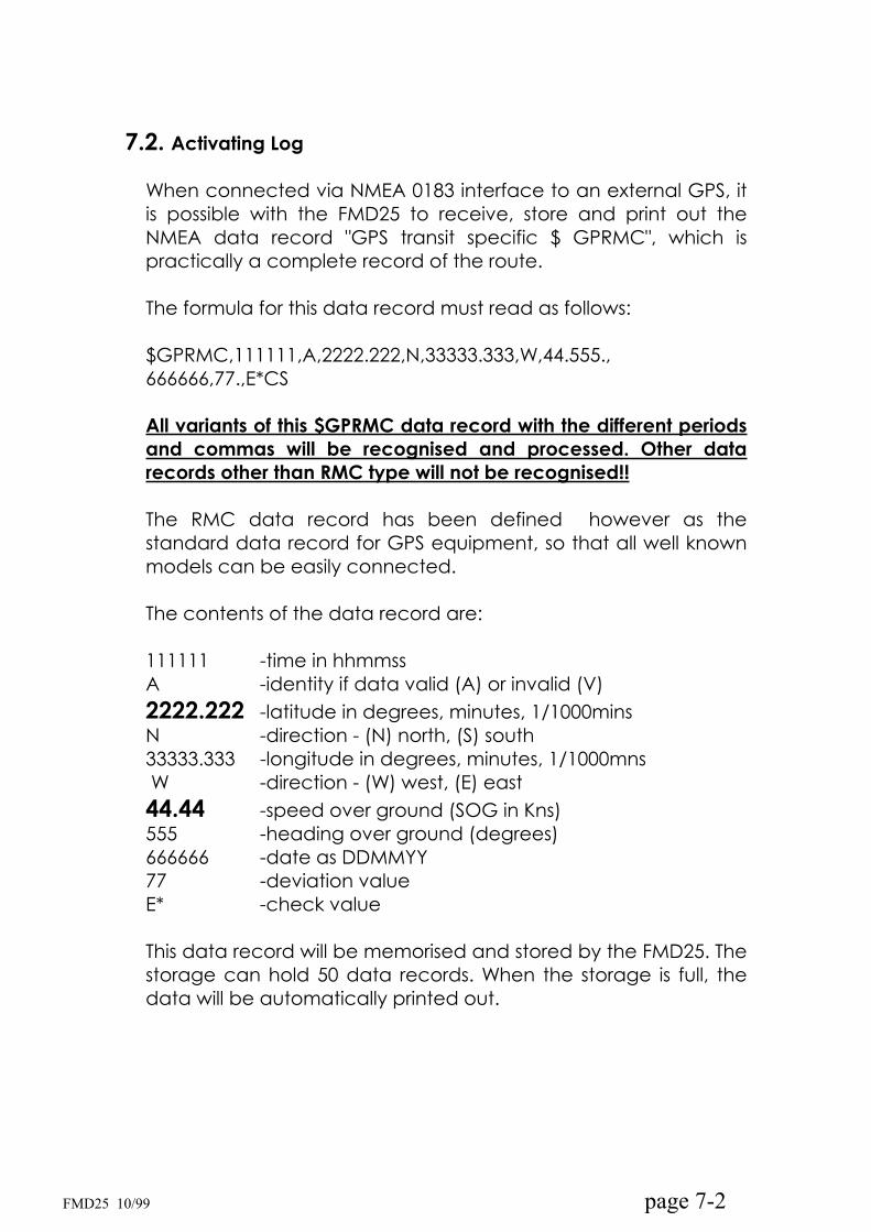
When connected via NMEA 0183 interface to an external GPS, it is possible with the FMD25 to receive, store and print out the NMEA data record "GPS transit specific $ GPRMC", which is practically a complete record of the route.
The formula for this data record must read as follows:
$GPRMC,111111,A,2222.222,N,33333.333,W,44.555.,666666,77.,E*CS
All variants of this $GPRMC data record with the different periods and commas will be recognised and processed. Other data records other than RMC type will not be recognised!!
The RMC data record has been defined however as the standard data record for GPS equipment, so that all well known models can be easily connected.
The contents of the data record are:
111111 -time in hhmmss A -identity if data valid (A) or invalid (V) 2222.222 -latitude in degrees, minutes, 1/1000mins N -direction - (N) north, (S) south33333.333 -longitude in degrees, minutes, 1/1000mns W -direction - (W) west, (E) east44.44 -speed over ground (SOG in Kns) 555 -heading over ground (degrees) 666666 -date as DDMMYY77 -deviation valueE* -check value
This data record will be memorised and stored by the FMD25. The storage can hold 50 data records. When the storage is full, the data will be automatically printed out.
page 7-2 FMD25 10/99

To control the continual amount of data, two parameters can be selected to define the information according to your personal wish.
Parameter 1: time from 1 to 99 minutes
You can select, in which time intervals the position should be stored, even when there has been no movement (e.g. at anchor, in berth).
If <00> is entered as time parameter, there will be no time-defined entry. This savesdata records being stored and printed out, when the vessel is stationary for a longer period of time.
Parameter 2 : positional movement in minutes (1 to 9nm)
You can also select, independent from the time interval, a distance after which the position of your vessel should be documented. For easy calculation, the values north/south and east/west are separated.
To activate the log:
press <SET UP> key press no. 2 to enter GPS LOG
to activate the log function press <YES>. (press <NO> to switch off)use cursor <DOWN> to spring to position TIME
select the TIME interval with keys <YES>/<NO>
use cursor <DOWN> to spring to position WAY
select the WAY interval with keys <YES>/<NO>
press key <EXIT> 4 times to return to stand-by
page 7-3 FMD25 10/99
The FMD25 navigation log function will work even when other functions e.g. reception, decoding are in process. Only when an incoming NAVTEX message or a longer decoding is taking place, will the position log be interrupted, however it will commence immediately at the end of the message. At any given time, 50 position data will be stored. After every 50th value, the storage will be printed out automatically. This does not take place during message decoding or when the FMD25 is being operated manually, but as soon as the FMD25 returns to the stand-by mode.
However, you can print out the actual stored data at any time. To do this:
call up the GPS LOGpress <PRINT>
When the print out has ended, the display will ask:
<DELETE ALL?>
Press <YES> to delete all position data in the storage or press <NO>to save the data. On receipt of new data, the oldest will be automatically deleted.
Using the above function, it is manually possible to print out the log daily. An automatic deletion after print out was deliberately waived to make it possible to repeat the print out, should there be a printer error.
page 7-4 FMD25 10/99
8. System (SET UP)
8.1 Setting of Time and Date
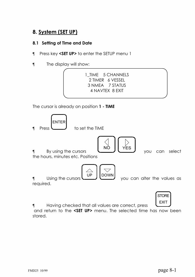
Press key <SET UP> to enter the SETUP menu 1
The display will show:
1_TIME 5 CHANNELS 2 TIMER 6 VESSEL 3 NMEA 7 STATUS
4 NAVTEX 8 EXIT
The cursor is already on position 1 - TIME
Press to set the TIME
By using the cursors you can selectthe hours, minutes etc. Positions
Using the cursors you can alter the values as required.
Having checked that all values are correct, pressand return to the <SET UP> menu. The selected time has now been
stored.
page 8-1 FMD25 10/99

8.2. Setting of Owner's and Vessel's Names
The name of the owner and of the ship can be entered into the FMD25. They will then appear on the bottom line at the end of each print out.
use the cursor <DOWN> to spring to position 6 – VESSEL
press <ENTER> to call up menu position 1 OWNER.The display will show:
ABCDEFGHIJKLMNNPQRSTUVWXYZ -_
OWNER´s NAME
Using the cursors <YES> and <NO> you can select the letters A to Z, (-) hyphens and (_)spaces. The selected letter is allotted by pressing <DOWN>. The letter can be deleted again by pressing <UP>. When the owner's name has been correctly selected, press <ENTER> to store.
The same procedure should be used for storing the vessel's name.
Use cursor <DOWN> to spring to menu position <2> SHIP (Press <ENTER> to call up above display.
page 8-2 FMD25 10/99
8.3. Print Out of System Data
The following system data can be printed out:
Navigation log ON/OFF and (by ON) trigger parameters programmed reception channels and their modemessage storage message direct print out programmed timer status 1 to max. 9 unit type and version number name of owner and ship if entered
To activate the print out:
press <DOWN> and spring to position 7 - <STATUS>press <ENTER> to commence printing
NAVTEX parameters can be printed out separately under menu position 3 - NAVTEX.
Data storage:
All stored data, such as system parameters, receiver parameters, timer status, stored messages etc. remain stored for at least 3 months, and under optimal conditions up to 12 months. This is possible because of the integrated NiCd battery, which is continually charged when the unit is in operation.
It is recommended that in a case, where the unit should be out of operation for a longer period, that you print out the system data and the NAVTEX parameters and file them. Should their be a loss of data, you can re-enter the old data from the print out.
page 8-3 FMD25 10/99

8.4. Memory Store, Deletion and Reset
All programmed system parameter data can be deleted i.e. can be reset to the standard parameters. Equally, all stored messages can be deleted. In this case the programmed timer status, navigation log status and NAVTEX parameters will also be deleted.It is therefore recommended, that you print out the system and NAVTEX status, before you commence this function (see chapters 8.3. and 5.7.)
To activate the deletion function:
1. Switch off the unit - <OFF>
2. Hold key <NO> and3. Switch on - <ON>
4. Release key <NO>
The display will show:
Clear whole memory ?
YES / NO
5. answer by pressing <YES> or <NO>6. Switch the unit off for a few seconds and switch on again.
All data and news programmable, are deleted and can now be newly programmed.
page 8-4 FMD25 10/99
9. Installation
9.1. Delivery contents
Please check, that the following contents, necessary for the installation of the FMD 20 are supplied:
1 pc pre-assembled power connection cable 2 pcs universal mounting brackets 4 pcs self holding spacers 4 pcs lock washers M5 4 pcs t thumbscrews M5 1 pc spare fuse 2A slow-blow 5 x 20mm 1 pc fuse, 300mA slow-blow 5 x 20mm (active antenna) 1 pc mounting hole template 1 pc instruction manual
9.2. Installation of unit
The two universal mounting brackets allow:
Desk top fitting wall fitting ceiling fitting
Additionally the FMD25 can be fitted at 4 different angles. Screw the brackets with the 4 screws to the wall or ceiling, using the adhesivetemplate in order to bore the holes in the correct positions.
On each side of the FMD25, there are two M5 threaded holes for fitting at the required angle with the thumb screws. Beforehand, press the self-holding spacers into the selected holes. These keep the brackets at a defined distance from the casing and has been accounted for in the template.
Before boring the holes, we recommend you to attach the brackets, power supply and antenna cables, and select the final mounting position.
Using the template, bore the holes in the exact positions and screw on the brackets. Hold the FMD25 at the selected angle and attach with the thumb screws into the holes with the spacers.
page 9-1 FMD25 10/99

ATTENTION
IMPORTANT INFORMATION
The FMD25 has two M5 threaded holes on either side for the supplied thumb screws, so that it can be fitted to the universal mounting bracket. The length of the thumb screws has been so determined, that, together with the bracket and the lock washers, they can only penetrate approx. 5mm into the thread.
Should you use alternative fitting methods or screws, please make sure that they do not penetrate the thread by more than 5mm.
By using longer screws, the integrated electronic could be damaged !!
page 9-2 FMD25 10/99

Dimensions:
page 9-3 FMD25 10/99

Desk Top Mounting
Wall Mounting:
page 9-4 FMD25 10/99

9.3. Power Supply Connection
Plug the pre-assembled cable supplied into the socket at the rear.The clip on connection is self-locking. To release, the lock clip must be pressed in the direction of the casing with a suitable tool.
The unit was manufactured to operate on a supply voltage of 11V to 15V DC (12V battery). The FMD25 has reverse battery and overvoltage protection. Should an incorrect connection take place, check the fuse and if necessary, replace.
The power cable is shielded to suppress disturbances. The open end is ready for connection and is fitted with a terminal strip.
The connection should be as near as possible to the distribution panel or the battery. It is most important, that the current is completely free of interference. Should there be any doubt, we recommend, that you fit a suppression filter.
Before switching on, we recommend you to test the polarity and the voltage at the terminals on the unit.
page 9-5 FMD25 10/99

9.4. NMEA Interface Connection
Using the FMD25 as navigation log or NMEA printer, the NMEA interface must be connected with an external NMEA device (e.g.GPS) The TX+ / TX- of the external unit must be connected to the RX+/ RX- of the FMD25.
9.5. Antenna and earth connection
The antenna socket is designed to be fitted to a coaxial cable connection with a BNC plug and impedance of 50 . No provisionhas been made for the connection of high impedance, unshielded antennæ.
The reception quality depends, to a high degree, on the quality of the antenna used. A good antenna guarantees good reception.
We recommend the use of a well tuned passive antenna or a high performance active antenna. Cheap active antenna do not provide the desired results due to bad cross-modulation characteristics.
Long wire antenna (e.g. on the back-stay) should be used in connection with an impedance matching balun transformer.
Important for good reception is of course good earthing of the ship's power supply and the FMD25. An adequately dimensioned grounding sponge and properly matched antenna will result in optimum performance.
For installation recommendations, see the following pages:
page 9-6 FMD25 10/99
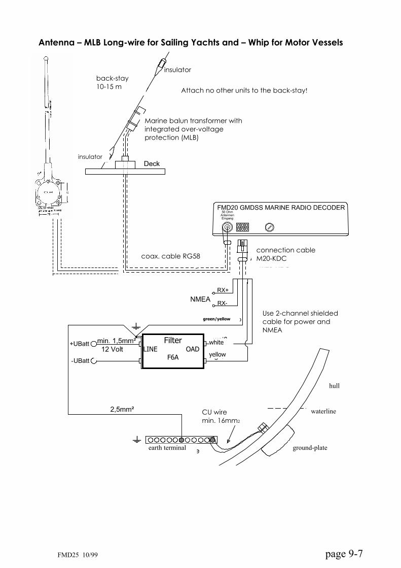
Antenna – MLB Long-wire for Sailing Yachts and – Whip for Motor Vessels
ground-plate
waterline
hull
insulatorback-stay10-15 m Attach no other units to the back-stay!
Marine balun transformer withintegrated over-voltageprotection (MLB)
insulator
coax. cable RG58 connection cable M20-KDC
FilterLINE OAD
F6A
CU wiremin. 16mm2
earth terminal
yellow
white
green/yellowUse 2-channel shielded cable for power and NMEA
page 9-7 FMD25 10/99

MD-AA Active Antenna
yellow
white
CU wire min. 16mm²
Ground-plate
Earth terminal
waterline
hull
Suppression filter
F3A
YellowgreenX Use only 2-channel
shielded cable
Connecting
Cable M20-KDC
Coax. Cable RG58 up to 30 m RG213 over 30 m
Active antenna MD-AA
Antenna must be earthedMounting tubular holder must be connected with vessel’sground.
Best installation position is the highest point of vessel
page 9-8 FMD25 10/99
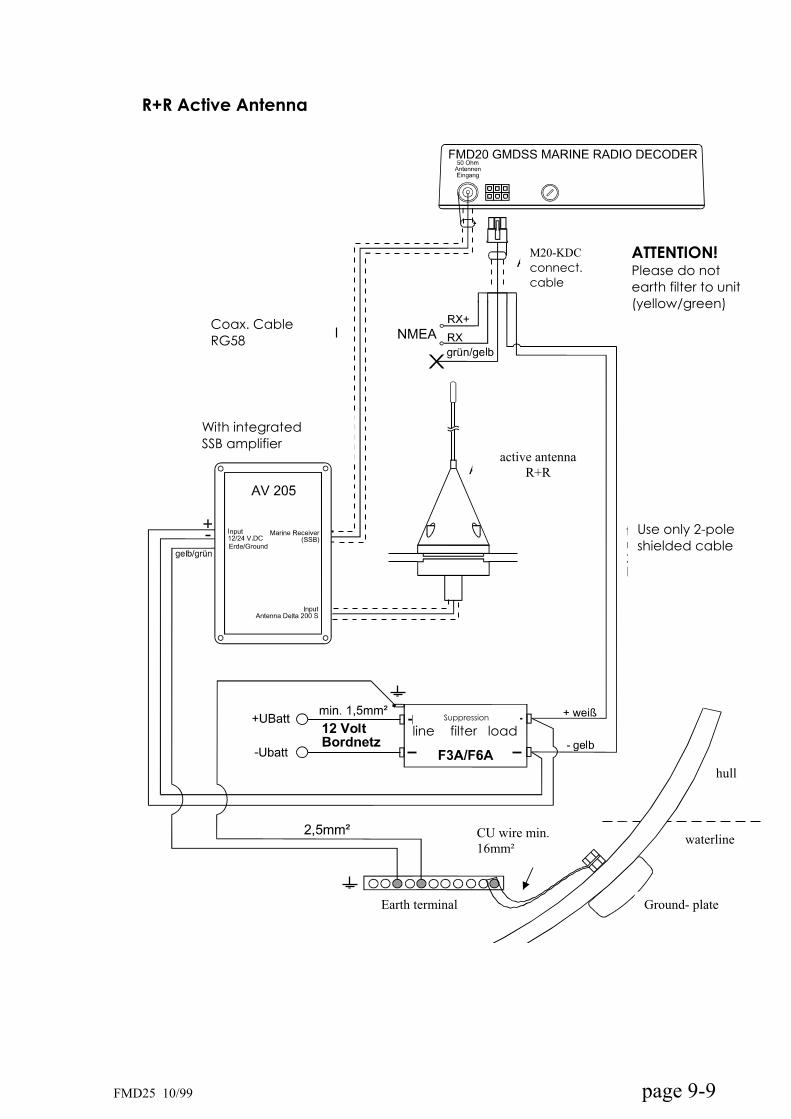
R+R Active Antenna
hull
waterline
Ground- plate
CU wire min.
16mm²
Earth terminal
Suppression
line filter load
Use only 2-poleshielded cable
active antenna
R+R
With integratedSSB amplifier
Coax. Cable RG58
M20-KDC
connect.cable
ATTENTION!Please do notearth filter to unit(yellow/green)
page 9-9 FMD25 10/99
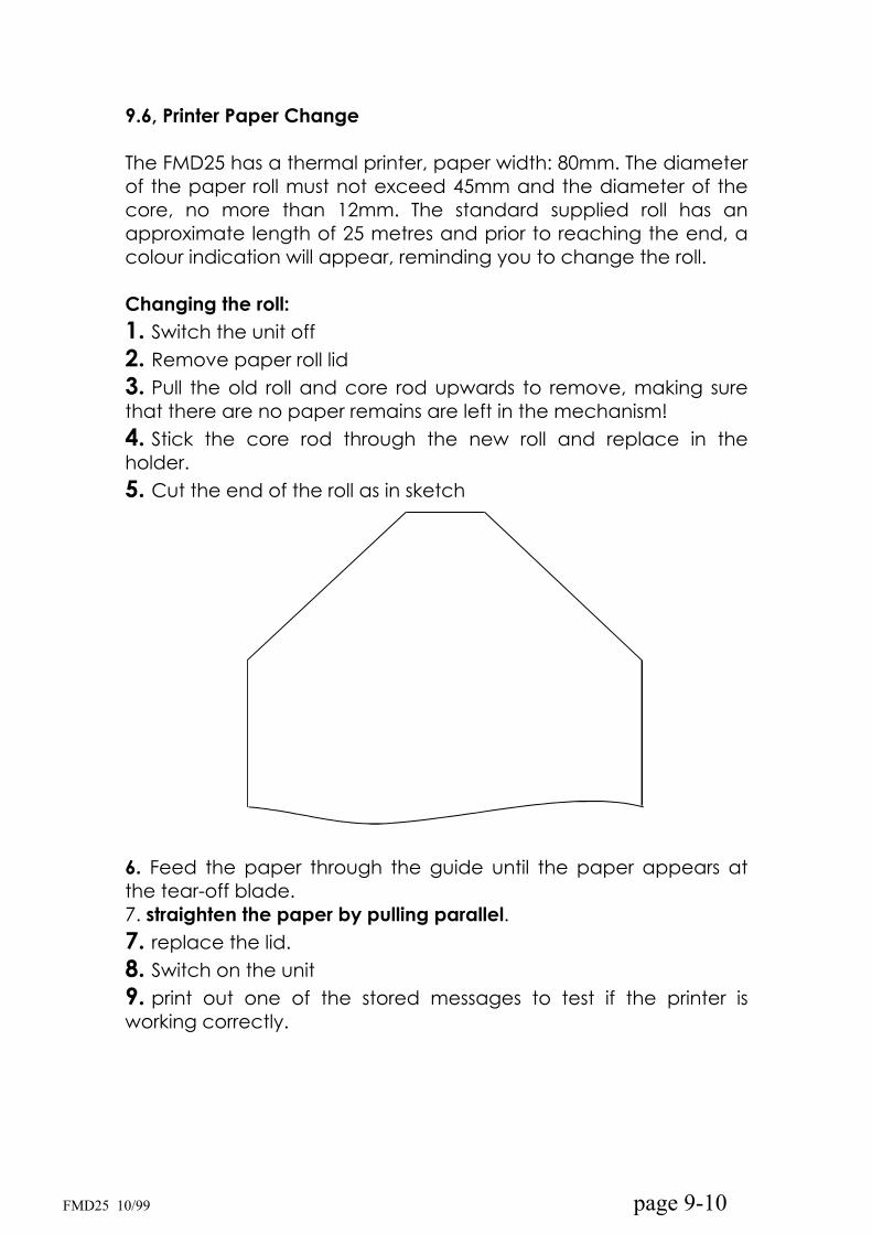
9.6, Printer Paper Change
The FMD25 has a thermal printer, paper width: 80mm. The diameter of the paper roll must not exceed 45mm and the diameter of the core, no more than 12mm. The standard supplied roll has an approximate length of 25 metres and prior to reaching the end, a colour indication will appear, reminding you to change the roll.
Changing the roll:
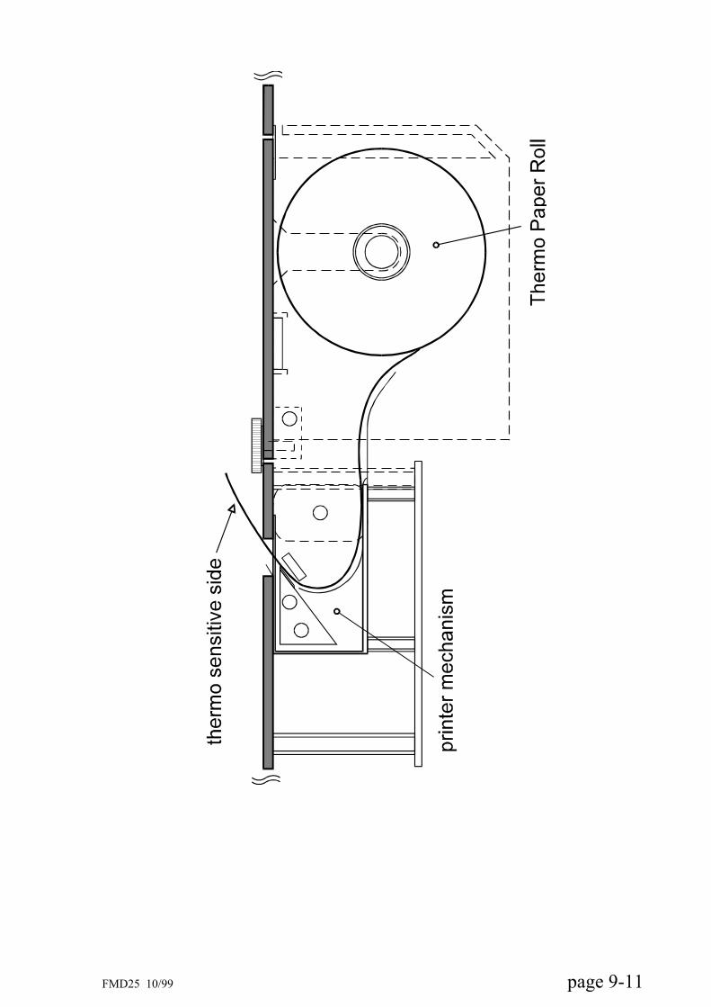
1. Switch the unit off 2. Remove paper roll lid 3. Pull the old roll and core rod upwards to remove, making sure that there are no paper remains are left in the mechanism! 4. Stick the core rod through the new roll and replace in the holder.5. Cut the end of the roll as in sketch
6. Feed the paper through the guide until the paper appears at the tear-off blade.7. straighten the paper by pulling parallel.7. replace the lid.8. Switch on the unit 9. print out one of the stored messages to test if the printer is working correctly.
page 9-10 FMD25 10/99
page 9-11 FMD25 10/99
9.7. Active Antenna Power Supply
The FMD25 has an integrated feeder for a power supply of 12V and maximum current consumption of 250mA, for an active antenna, which means that any interconnected supply units in the antenna cable are superfluous.
This supply unit is not activated when leaving the factory, because when attaching a balun transformer (impedance matcher), there would be a short circuit burden and other types of antennæ would have a 12V burden on the coupling.
To activate the power supply for the active antenna:
remove the lid of the unit by unscrewing the six screws on the rear of the unit. Put in the 5 x 20mm / 500mA tubular glass fuse which is supplied into the fuse holder next to the main fuse.
ATTENTION:SHOULD IT BE NECESSARY TO CHANGE THIS FUSE AT ANY TIME, NEVER USE STRONGER FUSES, AS THIS COULD LEAD TO DESTRUCTION OF POWER SUPPLY PARTS!!
9.8. Audio output
The FMD25 does not have a LF amplifier nor integrated speakers.This means one cannot hear or control acoustically. For every day use, this is unnecessary with the FMD25, as the signal strength is displayed. Maximum is twelve arrows but from seven arrows upwards, the signal is strong enough to be decoded. However the strength of the signal can be influenced by strong noise ratio or interfering signals.
Optionally, you can order a shielded cable of about 50cm and a 3.5mm jack, on which there is an LF signal sound of approximately 1 Vpp, which can be made audible over a suitable amplifier and speaker.
Fastnet Radio offer a loudspeaker with integrated 12V DC amplifier, which can be connected simply to the 3.5mm jack.
page 9-12 FMD25 10/99
10. FMD25 accessories
10.1. 24V DC/DC converter
The FMD25 can be operated with a DC/DC converter. This offers the followingadvantages:
input voltage range 9V to 36V
constant output voltage 12.5VThis means that the FMD25 can be operated by 12V and 24V batteries. The DC/DCconverter has an integrated filter, which suppresses interference from the ship's voltagesupply and offers additionally, a galvanic separation between the power supply and the unit. (An advantage for aluminium hulls).
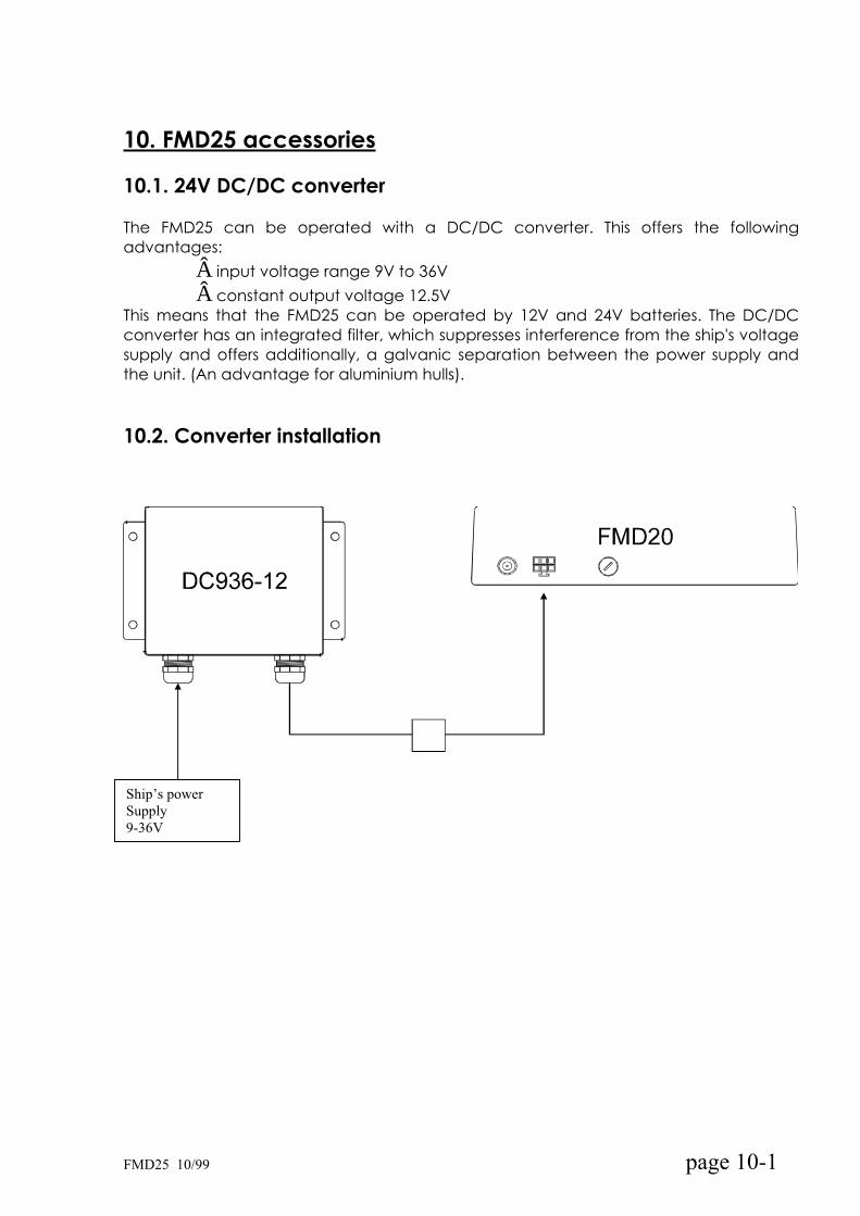
10.2. Converter installation
Ship’s power
Supply
9-36V
FMD25 10/99 page 10-1
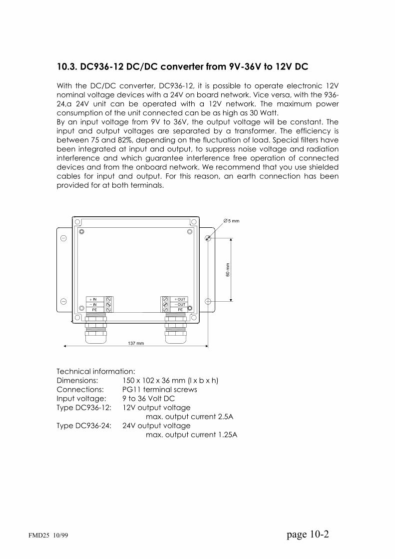
10.3. DC936-12 DC/DC converter from 9V-36V to 12V DC
With the DC/DC converter, DC936-12, it is possible to operate electronic 12Vnominal voltage devices with a 24V on board network. Vice versa, with the 936-24,a 24V unit can be operated with a 12V network. The maximum power consumption of the unit connected can be as high as 30 Watt.By an input voltage from 9V to 36V, the output voltage will be constant. Theinput and output voltages are separated by a transformer. The efficiency isbetween 75 and 82%, depending on the fluctuation of load. Special filters havebeen integrated at input and output, to suppress noise voltage and radiationinterference and which guarantee interference free operation of connected devices and from the onboard network. We recommend that you use shieldedcables for input and output. For this reason, an earth connection has been provided for at both terminals.
Technical information:Dimensions: 150 x 102 x 36 mm (l x b x h)Connections: PG11 terminal screws Input voltage: 9 to 36 Volt DC Type DC936-12: 12V output voltage
max. output current 2.5AType DC936-24: 24V output voltage
max. output current 1.25A
FMD25 10/99 page 10-2

10.4. MD-AA Active antenna for FMD25, 50 and 55
FMD25 10/99 page 10-3
Active reception antenna for 100 kHz to 30 MHz
The MD-AA active antenna has been specially developed and tuned for the Fastnet Radio GMDSS Marine Decoder series FMDxxx, but can also be used for any other receiver in the above reception range.It was mainly designed for the reception of verticallypolarised waves in the long, medium and shortranges.Extra value has been placed on a greater spacinginterval between the signal and the interferencelevel, rather than reaching a higher output potential.Carefully tuned for this purpose, the antennaelectronics adapt themselves to a low noise level,vertical linear impedance transformer, which guarantees the highest possible signal interferenceimmunity. By using the most modern shielded circuits,damage, caused by over-voltage, such as atmospheric or electrostatic lightning, will generallybe ruled out.The electronics are installed in a shockproof, UV and oil resistant casing, which optimally protects themagainst mechanical or atmospheric damage. The robust N-connection in the antenna is weatheringresistant.A fitting coaxial cable (RG214/RG58) servessimultaneously to branch off reception signals as well as to supply the distribution voltage.A universally fitting mount for the installation ontubular or plain surfaces is standard supply.The latest versions of FMDs have an integratedantenna -adapted power supply, which can be activated on desire.In this case, only a suitable coaxial cable,connected to the decoder's antenna input, is required, making the additional installation of an antenna power supply unnecessary.
Technical data.
Frequency range: 100kHz to 30MHzNomin. impedance: 50VSWR <2 HF connection: N-socketPower supply: via HF connectionVoltage: 12V DC (10 - 16V)Consumption: max. 65mA at 12VDistortion: 2. Level E1=E2=0V/m type 75dB
3. level E1=E2=0V/m type 95dBDimensions: see sketchWeight: approx. 400 grams
Ordering information:
MD-AA Antenna incl. mounting and
N-socket for RG58U
AA-PS (optional) power supply
Temperature range: -25°C to +55°C
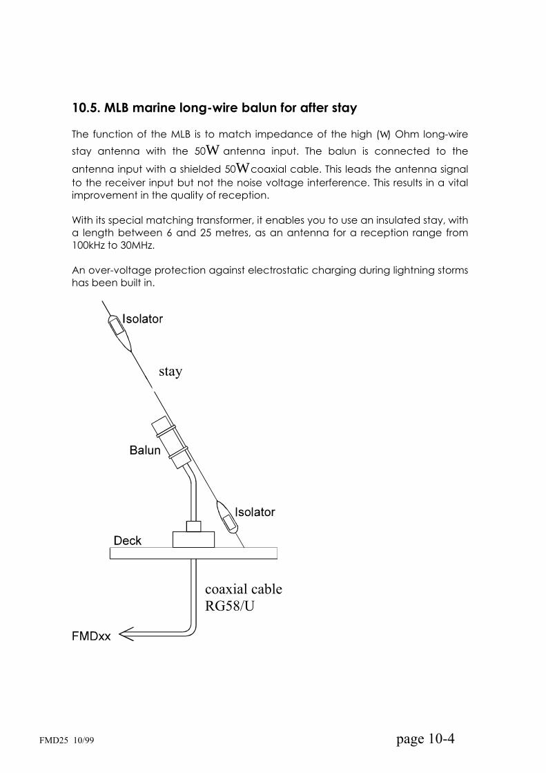
10.5. MLB marine long-wire balun for after stay
The function of the MLB is to match impedance of the high ( ) Ohm long-wire
stay antenna with the 50 antenna input. The balun is connected to the
antenna input with a shielded 50 coaxial cable. This leads the antenna signalto the receiver input but not the noise voltage interference. This results in a vitalimprovement in the quality of reception.
With its special matching transformer, it enables you to use an insulated stay, witha length between 6 and 25 metres, as an antenna for a reception range from 100kHz to 30MHz.
An over-voltage protection against electrostatic charging during lightning stormshas been built in.
stay
coaxial cable
RG58/U
FMD25 10/99 page 10-4
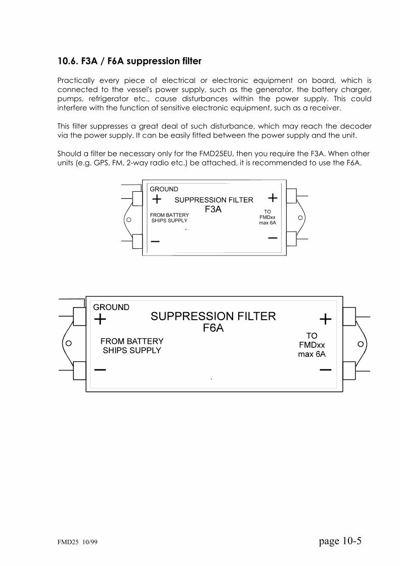
10.6. F3A / F6A suppression filter
Practically every piece of electrical or electronic equipment on board, which isconnected to the vessel's power supply, such as the generator, the battery charger,pumps, refrigerator etc., cause disturbances within the power supply. This could interfere with the function of sensitive electronic equipment, such as a receiver.
This filter suppresses a great deal of such disturbance, which may reach the decodervia the power supply. It can be easily fitted between the power supply and the unit.
Should a filter be necessary only for the FMD25EU, then you require the F3A. When other units (e.g. GPS, FM, 2-way radio etc.) be attached, it is recommended to use the F6A.
FMD25 10/99 page 10-5
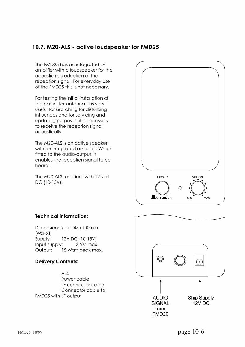
10.7. M20-ALS - active loudspeaker for FMD25
The FMD25 has an integrated LF amplifier with a loudspeaker for theacoustic reproduction of the reception signal. For everyday use of the FMD25 this is not necessary.
For testing the initial installation ofthe particular antenna, it is veryuseful for searching for disturbinginfluences and for servicing andupdating purposes, it is necessaryto receive the reception signalacoustically.
The M20-ALS is an active speaker with an integrated amplifier. Whenfitted to the audio-output, it enables the reception signal to be heard..
The M20-ALS functions with 12 voltDC (10-15V).
Technical information:
Dimensions:91 x 145 x100mm (WxHxT)Supply: 12V DC (10-15V)Input supply: 3 Vss max.Output: 15 Watt peak max.
Delivery Contents:
ALSPower cableLF connector cable Connector cable to
FMD25 with LF output
FMD25 10/99 page 10-6

11. Technical Data
11.1. General:
Dimensions : Receiver 222 (W) x 146 (H) x 55 (D) mm incl. brackets 288 (W) x 170 (H) x 65 (D) mm
Weight : approx. 1.5 kg Power Supply : 12 V nominal (11 to 15 V DC),
: optional 10 to 36 V Power Consumption : 200 mA in Stand-by,
: 350 mA operating, 1,2 A printing
Fuse : Spare Fuse, 2 A slow blow, 5x20mm
11.2. Receiver:
Frequency Range : 490,0 and 518,0 kHz (NAVTEX) and 8 channels between 100 kHz to 15 MHz
Modulation : AM, SSB (USB and LSB), FSK, CW Receiver System : Double Superheterodyne Receiver with
PLL Synthesiser tuning IF 1 : 44.999 to 45.000 MHz IF 2 : 455 kHz 1. ZF Filter : 45 MHz / 15 kHz 2. ZF Filter : 2,2 kHz (6dB) Audio Filter : 900 - 1700 Hz Display : LCD panel display, showing
Frequency, Operating mode - CW, FSK
Field strength,Memory location
Antenna Input : 50 Ohm asym., BNC Connector Audio Output Power : 1 Volts pp
11.3. Micro-controller
System Processor : SAB80C535 Siemens (M25) Program Memory : 64K x 8 EPROM (V2.01) Data Memory : 32K x 8 Static RAM System Clock : 15,360 MHz

11.4 Signal-Converter - Decoder
Converter : NF PLL lock system Decoding : Morse 40 tp 100 Bpm
RTTY 50 Baud SITOR 100 Baud
NAVTEXTimer : 9 - user programmable
11.5. LCD Display
Display module : L2014 Seiko or equivalent Display area : 71 X 21 mm Resolution : Text mode 4 lines 20 rows Back-lighting : LCD backlit
11.6. Printer
Printer mechanism : MTP 401 Seiko Printer head : Thermal head printer Resolution : 5 x 7 pixel per character Printer speed : 0,6 characters per second Paper width : 80 mm, Print width 67 mm Print head life : 5 x10⁷ characters, 30 km
11.7. NMEA Interface (receive only!)
Interface : NMEA 0183 Baud rate : 4800 baud Data String : $GPRMC for log
11.8. Supply for Active Antenna
Supply : nom. 12 V Current : max. 250 mA Fuse : Spare Fuse, 500 mA slow blow, 5x20mm
11.9. Approvals
CE Conformity ExplanationInspected by IEC 945 3rd edition Basic Standard for GMDSS Equipment

12. Information Stations, Reception Conditions
12.1. Stations, Frequencies and Transmission Times
The most complete and exact listing is to be found in the
Admiralty List of Radio Signals Volume 3 Radio Weather Services and Navigational Warnings
An annually up-dated edition is issued by :
Hydrographer of the Navy Admiralty List of Radio Signals Taunton Somerset TA1 2DN United Kingdom Tel: +44 1823 337900 Fax: +44 1823 334752
This book can be purchased by Fastnet Radio or in every qualified nautical bookshop.
Fastnet Radio prepare the latest information for the most important sailing regions in Europe and will gladly send this on request.
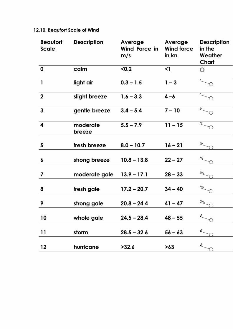
12.10. Beaufort Scale of Wind
BeaufortScale
Description AverageWind Force in m/s
AverageWind force in kn
Descriptionin the WeatherChart
0 calm <0.2 <1
1 light air 0.3 – 1.5 1 – 3
2 slight breeze 1.6 – 3.3 4 –6
3 gentle breeze 3.4 – 5.4 7 – 10
4 moderatebreeze
5.5 – 7.9 11 – 15
5 fresh breeze 8.0 – 10.7 16 – 21
6 strong breeze 10.8 – 13.8 22 – 27
7 moderate gale 13.9 – 17.1 28 – 33
8 fresh gale 17.2 – 20.7 34 – 40
9 strong gale 20.8 – 24.4 41 – 47
10 whole gale 24.5 – 28.4 48 – 55
11 storm 28.5 – 32.6 56 – 63
12 hurricane >32.6 >63


12.11. Beaufort Scale of Waves
See table on page 417 of the Admiralty List of Signals NP 283(1).

12.12. Propagation of SW Signals
One of the questions raised frequently is to determine which transmissions can be received at what distance from the transmitter. There are a number of factors that affect short-wave reception and distance vary greatly depending on time of day and year, sun activity and amount of traffic in a particular band. Each band has its own characteristics and as a thumb-rule says, one could say ‘the higher the frequency, the greater the distance’, at least during day time. At night there is also a considerable increase in the distance for low frequency bands. For instance, a typical transmitter in the 4 MHz band would cover a distance of 250 nm around noon time which would increase to as much as 2,500 nm at night. The following comparison looks at the various bands and their respective propagation characteristics.
2 MHz Band: Maximum distance during day time is about 60 nm which increases at night to 200 nm under good conditions. Thunder storms and lightning severely affect reception quality.
4 MHz Band: Reception in this band works best in the early morning hours with a gradual decline towards noon time. Towards the evening propagation may exceed 2000 nm. Reception of transmitters in closer proximity may not be possible.
8 MHz Band: Best propagation during the early morning hours. Distances up to 800 nm should be possible during the entire day. Reception of transmitters in closer proximity may not be possible.
12 MHz Band: Until late afternoon no long distance coverage. Thereafter propagation increases gradually but transmitters located within 600 nm may not be received.
16 MHz Band: This band is similar to the 12 MHz band. Reception of stations within 800 nm is not normally possible. In the late evening hours propagation increases to 6000 nm.
22 MHz Band: This band is not normally usable for stations located within 1000 nm. under good atmospheric conditions distances of up to
8000 nm may be covered. Best connections are obtained in North / South direction. Right after sunset this band is not usable.

12.13 Reception Antennæ onboard Vessels
Radio receivers are today standard equipment on board sea-going vessels.
In most cases it is seldom taken into account, that every receiver, no matter how expensive it is, can only function as good as its antenna.
What should one take into consideration when choosing an antenna?
The frequency range of the antenna must have the same range as the receiver, at least have the same range that is going to be used.
The output impedance of the antenna must match the input impedance of the receiver. In other words, the antenna and the receiver must conform.
The antenna and the cables leading to the receiver should transmit the least possible interference to the receiver. This entails proper grounding of the receiver and the antenna.
Receivers used in the maritime sector are usually 100 kHz to 30 MHz, i.e. are designed for use in the lowest LW ranges to the highest SW range. This corresponds to a wave range of approx. 3000 to 10 metres, an extremely vast range. Since the ratio of the length of an adapted antenna is always in fixed proportion to the wave-length, it is understandable that a long-wire antenna of a certain length can only be correctly adapted to one single frequency. Therefore, when using a long-wire antenna such as an insulated back-stay, it is necessary to fit between the antenna and the receiver cable, a suitable adapter. Such adapters exist (e.g. MLB marine longwire balun), which solve the problem as adapter with a large frequency range between the longwire and the shielded lead cable quite satisfactorily. The antenna itself should be as high as possible and installed as far away as possible from local disturbances. Practically every electric and electronic piece of equipment transmit interference signals which should not reach the unit via the antenna. New equipment with corresponding approvals or CE seals have been designed and constructed, free of disturbance as far as is possible. Measurements must betaken to make older units free of interference. The lead from the antenna to the receiver must be a non-dissapative well shielded coaxial cable with the same impedance as the receiver input. These are usually laid parallel to other (disturbing) cables and near other electrical devices. A badly shielded cable picks up local interference and transmits them to the receiver. The receiver itself should be connected at the shortest possible distance to a grounding sponge.
Alternatively an active antenna can be used. The input resistor in the amplifier of an active antenna is very high, therefore it requires a very short whip. The output resistor of the amplifier is 50 throughout the whole of the specified frequency range, so that a corresponding coaxial cable also with 50 which transmits the signal from the antenna without further loss of adaptation. The difficulty in the realisation of a good active antenna is that the integrated amplifier and the impedance transformer are as linear as possible and not overmodulated by strong signals from nearby transmitting stations creating self generated interference to the receiver. This is normally only possible with powerful amplifiers with equally high voltage use demands finding a good solution between highest possible linearity and the least amount of draw of current. Because of the small dimensions, it is easier to find a place for mounting an active antenna away from disturbing influences. The lead to the receiver through the shielded coaxial cable is uncritical. The use of a high quality active antenna will give an optimum reception.

12.14. MORSE Code Table
The FMD25 will recognise the following code and translate accordingly:
MORSE Code Character Remarks
– A
– – Ä
– – – Å,Á displayed as „a“
– B
– – C
– – – – CH
– D
E
– F
– – G
H
I
– – – J
– – K
– L
– – M
– N
– – – – Ñ displayed as „n“
– – – O
– – P
– – – Q
– R
S
– T
– U
– – Ü
– V
– – W
– – X
– – – Y
– – Z

MORSE Code Character Remarks
– – – – 1
– – – 2
– – 3
– 4
5
– 6
– – 7
– – – 8
– – – – 9
– – – – – 0
– – – – ) Closing Parenthesis
– – – ( Opening Parenthesis
– – / Slash
– – – + Plus symbol
– – – : Colon
– – – . Period
– – = Equal symbol / new line
– – ? Question mark
– – – – , Comma
– – „ Quote symbol
– – _-_ Minus Symbol, Hyphen
– – – – ´ Apostrophe, Accent
– – – _!_ Exclamation mark
– – – _+_ End of message
– – _sk_ End of transmission
_err_ Error
– -w- Please wait
– – _-_ Hyphen
– – – _sos_ Distress Call
Other national special signs or distorted characters are shown as an asterisk (*)

13. Examples
13. 1. Sation / Timer Programmierung
(Example North-Atlantik / North-Baltic Sea)
STATUS-INFORMATION
GPS-LOG : TIME: 99min DISTANCE: 3nm
STORED FREQUENCY CHANNELS:
CH FREQUENCY MODE ME PR STATION
01 147kHz RTTY Y Y Pinneberg
02 438kHz MORSE Y Y Lyngby
03 6.315kHz SITOR Y Y Portishead
04 4.583kHz RTTY Y Y Pinneberg
05 7.646kHz RTTY Y Y Pinneberg
06 4.211kHz SITOR Y Y Portishead
07 8.417kHz SITOR Y Y Portishead
08 10.100kHz RTTY Y Y Pinneberg
PROGRAMMED TIMER FUNCTIONS:
1. from 5:30 to 5:40 -> CH 1 Report, 12-hours Forcast
2. from 6:02 to 6:06 -> CH 1 Station-Message
3. from 10:35 to 10:50 -> CH 1 2-day Forcast
4. from 11:12 to 11:35 -> CH 1 5-day Forcast
GMDSS MARINE RADIO DECODER FMD25BN 1.1x
SHIP OWNER
ACHTUNG!Die aktuellen Sendezeiten entnehmen Sie bitte den Sendepläne in der
Admiral List of Radio Signals Volume 3 Band 1+2, dem Nautischen
Funkdienst oder dem Yachtfunkdienst. Fastnet Radio, Hamburg
informiert Sie auf Anfrage auch gerne über die aktuellen Sendepläne
der wichtigsten Sendestationen.
page 13-1 FMD25 10/99

13. 2. Sation / Timer Programmierung
(Example North-Atlantik / East-West Mediterranean Sea)
STATUS-INFORMATION
GPS-LOG : TIME: 99min DISTANCE: 3nm
STORED FREQUENCY CHANNELS:
CH FREQUENCY MODE ME PR STATION
01 4.202kHz MORSE Y Y Roma Meteo
02 4.343kHz MORSE Y Y Athen
03 6.315kHz SITOR Y Y Portishead
04 6.964kHz MORSE Y Y Bandirma
05 7.646kHz RTTY Y Y Pinneberg
06 8.530kHz MORSE Y Y Roma Meteo
07 11.039kHz RTTY Y Y Pinneberg
08 10.100kHz RTTY Y Y Pinneberg
PROGRAMMED TIMER FUNCTIONS:
1. from 0:50 to 1:20 -> CH 1 Report,IAR-ROMA
2. from 5:37 to 6:02 -> CH 8 5-day Forcast
3. from 9:40 to 10:05 -> CH 8 2-day Forcast
4. from 17:18 to 17:33 -> CH 8 Station-Message
GMDSS MARINE RADIO DECODER FMD25MS 1.1x
SHIP OWNER
ACHTUNG!Die aktuellen Sendezeiten entnehmen Sie bitte den Sendepläne in der
Admiral List of Radio Signals Volume 3 Band 1+2, dem Nautischen
Funkdienst oder dem Yachtfunkdienst. Fastnet Radio, Hamburg
informiert Sie auf Anfrage auch gerne über die aktuellen Sendepläne
der wichtigsten Sendestationen.
page 13-2 FMD25 10/99

13.3. Example NAVTEX Printout
Navtex message, Station Cullercoast, England
WZ 514
DOVER STRAIT. SANDETTIE LIGHTVESSEL 51-0
9N 01-47E FOG SIGNAL
UNRELIABLE.
NNN
NAVTEX 518 kHz GA04 12-03-94 0:53UTC
Navtex message, Splitradio
SLITRADIO NAV WNG 243/92
SINCE DEC 16TH 1992 N OF CLIFF MULO (43
31 06 N-15 55 30 E)
ANCHORED WAVEGRAPHIC STATION MAKED WITH
W-FLASHING LIGHT.
500 MTRS BERTH REQUESTEDE.
NNN
NAVTEX 518 kHz QA08 11-03-94 22:58UTC
Navtex message, Oostende Radio
241100 UTC DEC =
OST INFO 226/93 =
POS DOVER STRAIT AND RRENCH BEACHES
PLASTIC BAGS WITH DANGEROUS AND TOXIC
CHEMICALS IN POWDER ARE FOUND
SOME BAGS ARE DAMAGED AVOID TOUCHING
BAGS OR CHEMICALS
BAGS ARE EXPECTED TO BE OFF BELGIA COAS
T ON THE 26TH OF DECEMBER
NNN
NAVTEX 518 kHz TA23 10-2-94 02:10UTC
page 13-3 FMD25 10/99
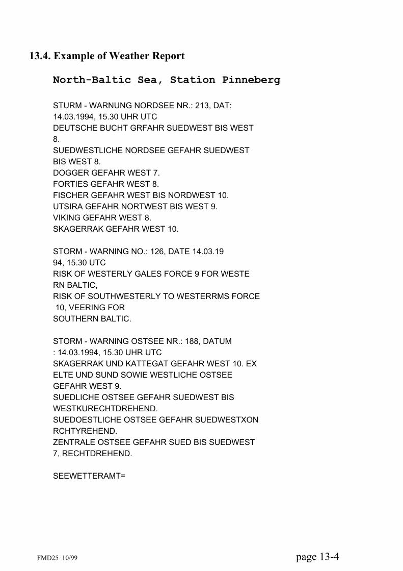
13.4. Example of Weather Report
North-Baltic Sea, Station Pinneberg
STURM - WARNUNG NORDSEE NR.: 213, DAT:
14.03.1994, 15.30 UHR UTC
DEUTSCHE BUCHT GRFAHR SUEDWEST BIS WEST
8.
SUEDWESTLICHE NORDSEE GEFAHR SUEDWEST
BIS WEST 8.
DOGGER GEFAHR WEST 7.
FORTIES GEFAHR WEST 8.
FISCHER GEFAHR WEST BIS NORDWEST 10.
UTSIRA GEFAHR NORTWEST BIS WEST 9.
VIKING GEFAHR WEST 8.
SKAGERRAK GEFAHR WEST 10.
STORM - WARNING NO.: 126, DATE 14.03.19
94, 15.30 UTC
RISK OF WESTERLY GALES FORCE 9 FOR WESTE
RN BALTIC,
RISK OF SOUTHWESTERLY TO WESTERRMS FORCE
10, VEERING FOR
SOUTHERN BALTIC.
STORM - WARNING OSTSEE NR.: 188, DATUM
: 14.03.1994, 15.30 UHR UTC
SKAGERRAK UND KATTEGAT GEFAHR WEST 10. EX
ELTE UND SUND SOWIE WESTLICHE OSTSEE
GEFAHR WEST 9.
SUEDLICHE OSTSEE GEFAHR SUEDWEST BIS
WESTKURECHTDREHEND.
SUEDOESTLICHE OSTSEE GEFAHR SUEDWESTXON
RCHTYREHEND.
ZENTRALE OSTSEE GEFAHR SUED BIS SUEDWEST
7, RECHTDREHEND.
SEEWETTERAMT=
page 13-4 FMD25 10/99
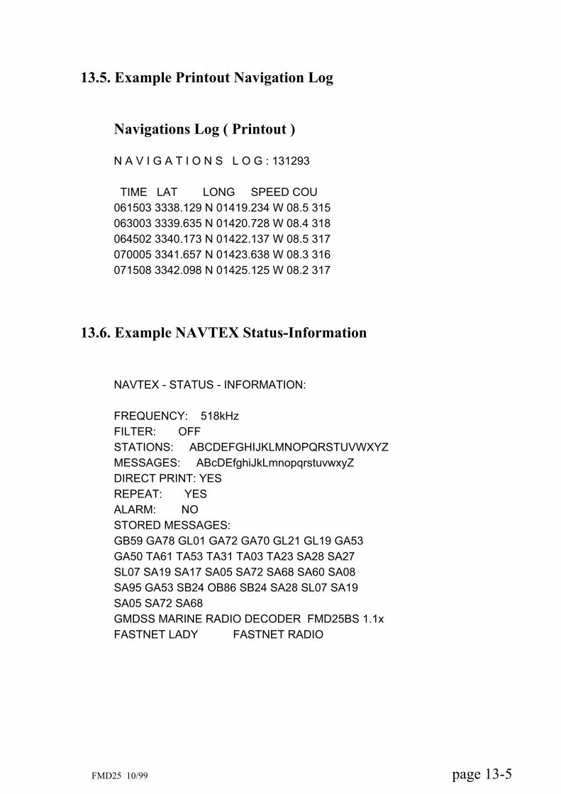
13.5. Example Printout Navigation Log
Navigations Log ( Printout )
N A V I G A T I O N S L O G : 131293
TIME LAT LONG SPEED COU
061503 3338.129 N 01419.234 W 08.5 315
063003 3339.635 N 01420.728 W 08.4 318
064502 3340.173 N 01422.137 W 08.5 317
070005 3341.657 N 01423.638 W 08.3 316
071508 3342.098 N 01425.125 W 08.2 317
13.6. Example NAVTEX Status-Information
NAVTEX - STATUS - INFORMATION:
FREQUENCY: 518kHz
FILTER: OFF
STATIONS: ABCDEFGHIJKLMNOPQRSTUVWXYZ
MESSAGES: ABcDEfghiJkLmnopqrstuvwxyZ
DIRECT PRINT: YES
REPEAT: YES
ALARM: NO
STORED MESSAGES:
GB59 GA78 GL01 GA72 GA70 GL21 GL19 GA53
GA50 TA61 TA53 TA31 TA03 TA23 SA28 SA27
SL07 SA19 SA17 SA05 SA72 SA68 SA60 SA08
SA95 GA53 SB24 OB86 SB24 SA28 SL07 SA19
SA05 SA72 SA68
GMDSS MARINE RADIO DECODER FMD25BS 1.1x
FASTNET LADY FASTNET RADIO
page 13-5 FMD25 10/99

FMD25 10/99 page 14-1
14. Appendix
14.1. Service and Maintenance
Your FMD25 has been designed to require only a minimum of maintenance. When changing paper rolls it is advisable to ascertain that dust that may have collected in the paper compartment is removed. There are no parts inside the case and service should be left to qualified personnel.
14.2. Service Organizations
This product has been designed and manufactured to the highest standards and has undergone rigorous testing in extreme environments. In the unlikely event that service may be required, the unit should be returned to the dealer from which it was purchased. If that presents a problem then service is available from any of the following organisations:
FASTNET RADIO AG Deelböge 5-7 22297 Hamburg Tel.: + 49 40 369898-0 Fax: + 49 40 369898-10 e-mail: [email protected]://www.fastnet.de

FMD25 10/99 page 14-2
Attention: Please return this unit to the dealer from whom it was purchased, for guarantee repairs. Whenever a unit is returned for servicing please include a complete fault description, a copy of your warranty card and / or proof of purchase.
FMD25 10/99 page 14-3
14.3. Warranties
Fastnet Radio guarantees, that each product is delivered faultless, in material and production, in accordance with the specifications.
The guarantee lasts for 12 months from the date of purchase on parts and labour expenditure. In the case of Inmarsat-E emergency systems the guarantee begins as from the first registration of the unit by Inmarsat. Expendable parts such as electric bulbs, fuses, batteries, ball bearings etc., are not covered by this warranty.
Guarantee service will be carried out world-wide by the authorised dealers or the national Fastnet Radio AG agents. Products purchased from Fastnet Radio AG, which are returned, will be repaired during normal working hours or replaced. Freight costs or customs duties and other incidental charges are at the expense of the purchaser. The maximum guarantee costs must in no way exceed the original price of the unit.
Servicing. The demand for servicing must be exclusively in writing. Fastnet-Radio will then control further developments. It can be arranged that servicing on board be carried out by teh nearest service partner. The man hours for the repair as well as the replacement of defect modules or other parts are free of charge as long as they are covered by the warranty. Overtime, waiting time, travel and hotel expenses,insurances, customs duties and other extra incidentals are at the expense of the purchaser. Additional costs involved in connection with testing or replacing of components such as docking, slipping, diving and protective measures and measurements are not covered by the Fastnet Radio AG warranty.
Validity: These warranty conditions are only valid when the warranty certificate or an invoice containing the serial number or the confirmation of registration of an emergecy system device. In addition, the installation and the operation must be carried out in accordance with the operator manual. The obligations of the warranty are not valid for damages to the equipment which have been caused by improper handling, accident, damage, lack of service, water irruption or unauthorised repair work.

FMD25 10/99 page 14-4
Fastnet-Radio does not take responsibility for loss also for reasons such as unforeseen damages emerging from contracts made elsewhere even though caused by faulty or unsatisfactory maintenance or in connection with the sale, the installation, the operation or repair of the product übernimmt keinerlei Haftung für Verlust, auch auf Grund anderweitiger Verträge entstandene Zufalls- oder Folgeschäden, auch wenn diese durch mangelnde Wartung hervorgerufen wurden oder im Zusammenhang mit dem Verkauf, der Installation, dem Gebrauch oder der Reparatur des Produktes stehen.For your information: Unforeseen damages range within a limited extent e.g. loss of profit, Zur Erläuterung: Folgeschäden umfassen in begrenztem Umfang z.B. Gewinnverluste, Schadenersatz und Personenschäden und sind nicht Teil des Gewährleistungsumfanges. Diese Garantie-bedingungen berücksichtigen die jeweils nationale Rechts-sprechung.
14.4. Software Update
A great number of features of this product are controlled by software which is secured in 2 EPROM firmware chips. Changes in particular requirements as well as general product improvements can therefore be updated by simply exchanging new EPROM chips against those installed. This can normally be done by a skilled technician and your dealer will gladly assist you. This manual contains a coupon for one free update. Further updates are chargeable and should be ordered through your dealer or directly from Fastnet Radio at the address mentioned above.
Up-date Enquiry : should you have an enquiry, lease fill out the attached form completely, and return it to Fastnet Radio

FMD25 10/99 page 14-5
14.5. Error Alarm
The FMD25 has an integrated control function . In case of an error, an acoustic alarm will sound. This is a combination of short and long beeb tones.
14.5.1. „PRINTER-ERROR“ Alarm
Should there be a fault in the printer (e.g. paper jam or end of the paper roll), the display will show “PRINTER ERROR”, at the same time an alarm will sound in the form of two short beebs. This will occur every 15 minutes. Should the fault occur during the decoding of a message, the message will be stored automatically and after the fault has been rectified, the message can be printed out. In this case switch off the unit after the decoding is finished, rectify the fault and switchon the unit again. The “PRINTER ERROR” alarm can be turned of by switching the unit OFF/ON for a few seconds.
Attention: The unit must be switched off for at least 5 seconds so that internally, a total reset can take place and the unit can re-activate itself accordingly.
14.5.2 Further Acoustic Error Alarms
Nr. Sequence Explanation Function
01 • LCD driver err_wait_01 12 •• LCD driver err_wait_2 02 • LCD driver err_wait_3 04 •. LCD driver err_wait_016 03 •• Printer Function err_prn19 •• • Time, date err_RTC20 • • Time, date err_RTC_set21 • • • err_sence
These error alarms can happen sporadically, caused by external or internal influence such as power fluctuation, interference in the power supply, static discharge etc.They can generally be reset by pressing the <EXIT> key. If this does not work,
Should this error alarm continue to to occur, then most likely there is a fault in the unit and should be brought to one of the authorised service centres to be examined.
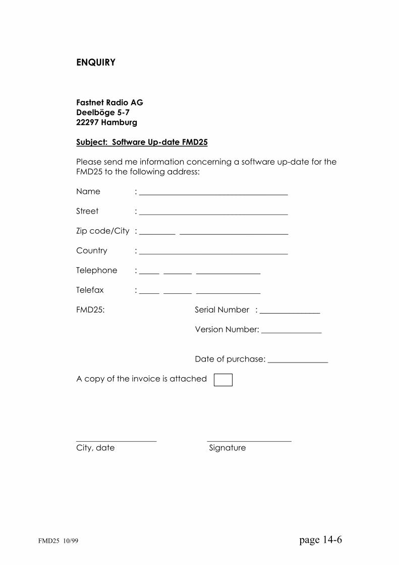
ENQUIRY
Fastnet Radio AG Deelböge 5-7 22297 Hamburg
Subject: Software Up-date FMD25
Please send me information concerning a software up-date for the FMD25 to the following address:
Name : _____________________________________
Street : _____________________________________
Zip code/City : _________ ___________________________
Country : _____________________________________
Telephone : _____ _______ ________________
Telefax : _____ _______ ________________
FMD25: Serial Number : _______________
Version Number: _______________
Date of purchase: _______________
A copy of the invoice is attached
____________________ _____________________ City, date Signature
FMD25 10/99 page 14-6


