32
1/8 80.40-4e FNA 008 · FNA 016 · Operating pressure up to 4 bar · Nominal flow rate up to 16 l/min · For tank capacities up to 1500 l Off-line Filter Units
1/8
80.40-4e
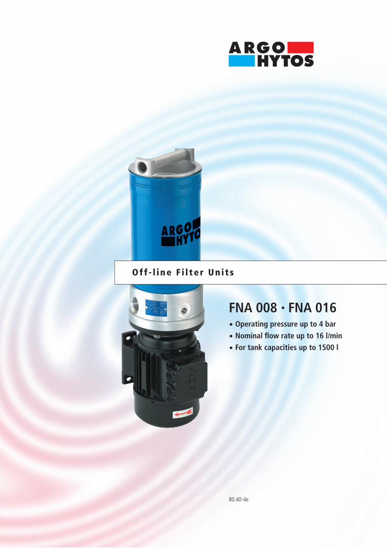
FNA 008 · FNA 016· Operating pressure up to 4 bar
· Nominal flow rate up to 16 l/min
· For tank capacities up to 1500 l
Off - l i ne F i l te r Un i t s
Descr ip t ion
ApplicationOff-line filtration in hydraulic and lubricating oil systems.
Performance featuresProtection against wear: By means of filter elements that meet even the
highest demands regarding cleanliness classes and dirt-holding capacity.
Protection againstmalfunction: By means of permanent filtration in the off-line
circuits excellent cleanliness classes can be achieved. This can lead to significantly longer intervals between maintenance work and oil changes, as well as reduction of machine failures due to contamination.
Special design featuresCover: The cover can be opened without special auxiliary tools. Because of the cover design the filter element can
be changed almost without losing any oil. No pipes are needed except for the connection lines. The power units feature minimal noise output and low power consumption.
Pressurerelief valve: An integrated PRV (pressure relief valve) protects against overload.Dirt retention valve: Ensures that dirt accumulated in the filter is removed
together with the element. Settled dirt cannot return into the system.
Filter elementsFlow direction from centre to outside. The star-shaped pleating of the filter material results in:• large filter surfaces• low pressure drop• high dirt-holding capacities• long service life
Filter maintenanceBy using a clogging indicator the correct moment for maintenance is stated and guarantees the optimum utilization of the filter life.
MaterialsPump housing: Aluminium alloyFilter housing: SteelCover: Aluminium alloySeals: NBR (Viton on request)Filter media: EXAPOR® - inorganic, multi-layer microfibre web
AccessoriesWater-absorbing filter elements (EXAPOR® AQUA) are available on request.With Part No. FNA 008.1700 a mounting set that facilitates the fitting of incoming and outgoing pipes onto an existing filling/venting connection is available.For installation in filter cooling circuits a version with by-pass valve is available on request.Electrical and optical clogging indicators are available.Dimensions and technical data see catalogue sheet 60.20.
Viscosity range
Tank capacityapprox. 2,4 l
Maximum suction height1,5 m
Operating pressureMax. 4 bar, pressure protection with pressure relief valve;cracking pressure see Selection Chart, column 11
Operating positionVertical, pump block at the bottom
Recommended tank capacitiesFNA 008: 100 l ... 800 lFNA 016: 400 l ... 1500 lOff-line filter units for tank capacities exceeding 1500 lsee catalogue sheet 80.50
Nominal flow rateUp to 16 l/min at ν = 35 mm²/s(see Selection Chart, column 2)
ConnectionThreaded port according to ISO 228 or DIN 13.Sizes see Selection Chart, columns 9 and 10
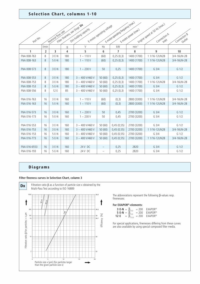
Filter fineness3 µm(c) ... 12 µm(c)β-values according to ISO 16889(see Selection Chart, column 3 and Diagram Dx)
Dirt-holding capacityValues in g test dust ISO MTD according to ISO 16889(see Selection Chart, column 5)
Hydraulic fluidsMineral oil and biodegradable fluids(HEES and HETG, see info-sheet 00.20)
Temperature range of fluids0 °C ...+65 °C (also see viscosity range)
Ambient temperature range0 °C ...+50 °C
Charac ter i s t i c s
Electro motor Continous Continous Short-termair cooled operation operation operationtype of protection: IP 55 min. max. max.
3 ~ 400 V / 460 V 15 mm²/s 200 mm²/s 400 mm²/s
1 ~ 230 V 15 mm²/s 200 mm²/s 400 mm²/s
1 ~ 110 V 15 mm²/s 100 mm²/s 200 mm²/s
24 V 15 mm²/s 100 mm²/s 150 mm²/s
Dx
l/min g V Hz kW min-1
1 2 3 4 5 6 7 8 9 10
Diagrams
Filter fineness curves in Selection Chart, column 3
Particle size x [µm] (for particles larger than the given particle size x)
Filtr
atio
n ra
tio β
for p
artic
les
> x
µm
Effic
ienc
y [%
]
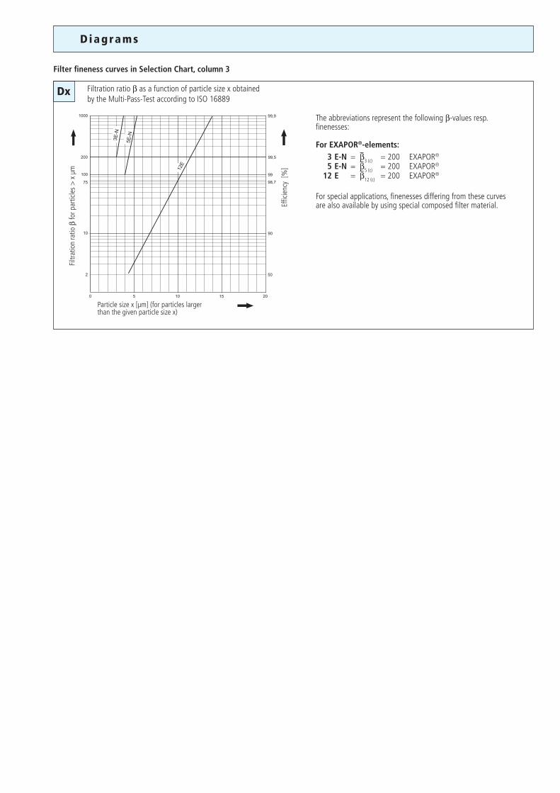
Filtration ratio β as a function of particle size x obtained by the Multi-Pass Test according to ISO 16889
The abbreviations represent the following β-values resp. finenesses:
For EXAPOR®-elements: 3 E-N = β3 (c) = 200 EXAPOR®
5 E-N = β5 (c) = 200 EXAPOR®
12 E = β12 (c) = 200 EXAPOR®
For special applications, finenesses differing from these curves are also available by using special composed filter media.
Se lec t ion Char t , co lumns 1 -10
E-moto
r power (
max.)
Filter fi
neness, se
e Diagr. D
x
E-motor operating vo
ltage
Dirt-holding ca
pacity
Nominal flow rate
Part No.
Engine speed
at 50 Hz (max.)
E-moto
r opera
ting fre
quency
(max.)
Connection A
In
let Connection B
O
utlet
FNA 008-763 8 3 E-N 180 1 ~ 110 V (60) 0,25 (0,3) 1400 (1700) 1 1/16-12UN2B 3/4-16UN-2BFNA 008-163 8 5 E-N 180 1 ~ 110 V (60) 0,25 (0,3) 1400 (1700) 1 1/16-12UN2B 3/4-16UN-2B
FNA 008-573 8 3 E-N 180 1 ~ 230 V 50 0,25 1400 (1700) G 3/4 G 1/2
FNA 008-553 8 3 E-N 180 3 ~ 400 V/460 V 50 (60) 0,25 (0,3) 1400 (1700) G 3/4 G 1/2FNA 008-753 8 3 E-N 180 3 ~ 400 V/460 V 50 (60) 0,25 (0,3) 1400 (1700) 1 1/16-12UN2B 3/4-16UN-2BFNA 008-153 8 5 E-N 180 3 ~ 400 V/460 V 50 (60) 0,25 (0,3) 1400 (1700) G 3/4 G 1/2FNA 008-556 8 12 E 85 3 ~ 400 V/460 V 50 (60) 0,25 (0,3) 1400 (1700) G 3/4 G 1/2
FNA 016-763 16 3 E-N 160 1 ~ 110 V (60) (0,3) 2800 (3300) 1 1/16-12UN2B 3/4-16UN-2BFNA 016-163 16 5 E-N 160 1 ~ 110 V (60) (0,3) 2800 (3300) 1 1/16-12UN2B 3/4-16UN-2B
FNA 016-573 16 3 E-N 160 1 ~ 230 V 50 0,45 2700 (3200) G 3/4 G 1/2FNA 016-173 16 5 E-N 160 1 ~ 230 V 50 0,45 2700 (3200) G 3/4 G 1/2
FNA 016-553 16 3 E-N 160 3 ~ 400 V/460 V 50 (60) 0,45 (0,55) 2700 (3200) G 3/4 G 1/2FNA 016-753 16 3 E-N 160 3 ~ 400 V/460 V 50 (60) 0,45 (0,55) 2700 (3200) 1 1/16-12UN2B 3/4-16UN-2BFNA 016-153 16 5 E-N 160 3 ~ 400 V/460 V 50 (60) 0,45 (0,55) 2700 (3200) G 3/4 G 1/2FNA 016-773 16 5 E-N 160 3 ~ 400 V/460 V 50 (60) 0,45 (0,55) 2700 (3200) 1 1/16-12UN2B 3/4-16UN-2B
FNA 016-6553 16 3 E-N 160 24 V DC – 0,25 2820 G 3/4 G 1/2FNA 016-193 16 5 E-N 160 24 V DC – 0,25 2820 G 3/4 G 1/2
Se lec t ion Char t , co lumns 11 -17
Cracking pres
sure of by-p
ass
Part No.
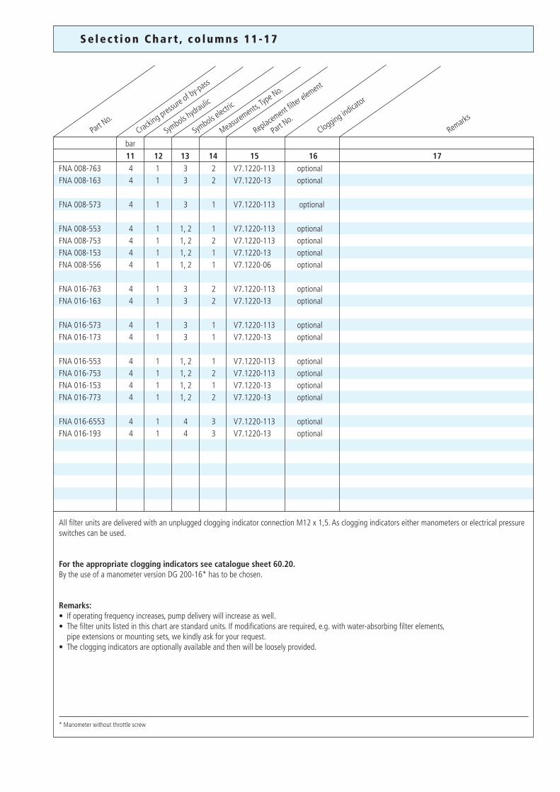
FNA 008-763 4 1 3 2 V7.1220-113 optional FNA 008-163 4 1 3 2 V7.1220-13 optional FNA 008-573 4 1 3 1 V7.1220-113 optional FNA 008-553 4 1 1, 2 1 V7.1220-113 optional FNA 008-753 4 1 1, 2 2 V7.1220-113 optional FNA 008-153 4 1 1, 2 1 V7.1220-13 optional FNA 008-556 4 1 1, 2 1 V7.1220-06 optional FNA 016-763 4 1 3 2 V7.1220-113 optional FNA 016-163 4 1 3 2 V7.1220-13 optional FNA 016-573 4 1 3 1 V7.1220-113 optional FNA 016-173 4 1 3 1 V7.1220-13 optional FNA 016-553 4 1 1, 2 1 V7.1220-113 optional FNA 016-753 4 1 1, 2 2 V7.1220-113 optional FNA 016-153 4 1 1, 2 1 V7.1220-13 optional FNA 016-773 4 1 1, 2 2 V7.1220-13 optional FNA 016-6553 4 1 4 3 V7.1220-113 optional FNA 016-193 4 1 4 3 V7.1220-13 optional
Clogging indicator
Remarks
Symbols e
lectric
* Manometer without throttle screw
All filter units are delivered with an unplugged clogging indicator connection M12 x 1,5. As clogging indicators either manometers or electrical pressure switches can be used.
For the appropriate clogging indicators see catalogue sheet 60.20.By the use of a manometer version DG 200-16* has to be chosen.
Remarks:• If operating frequency increases, pump delivery will increase as well.• The filter units listed in this chart are standard units. If modifications are required, e.g. with water-absorbing filter elements, pipe extensions or mounting sets, we kindly ask for your request.• The clogging indicators are optionally available and then will be loosely provided.
Symbols h
ydraulic
Replacement filter
element
Pa
rt No.
Measurements, T
ype No.
11 12 13 14 15 16 17bar
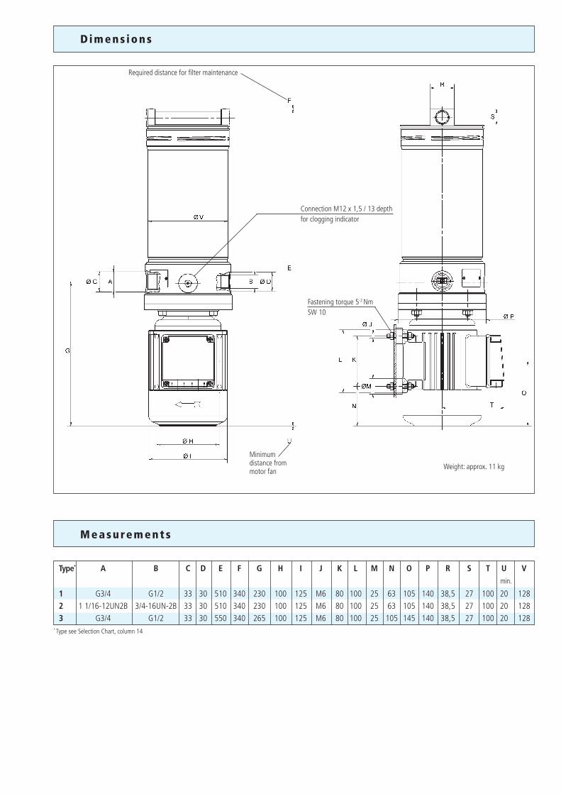
Dimens ions
Type* A B C D E F G H I J K L M N O P R S T U V min.
1 G3/4 G1/2 33 30 510 340 230 100 125 M6 80 100 25 63 105 140 38,5 27 100 20 1282 1 1/16-12UN2B 3/4-16UN-2B 33 30 510 340 230 100 125 M6 80 100 25 63 105 140 38,5 27 100 20 1283 G3/4 G1/2 33 30 550 340 265 100 125 M6 80 100 25 105 145 140 38,5 27 100 20 128
* Type see Selection Chart, column 14
Measurements
Required distance for filter maintenance
Connection M12 x 1,5 / 13 depthfor clogging indicator
Fastening torque 5-2 NmSW 10
Minimumdistance from motor fan
Weight: approx. 11 kg
We produce fluid power solutionsARGO-HYTOS GMBH · Industriestraße 9 · D-76703 KraichtalTel: +49 7250 76-0 · Fax: +49 7250 76-199 · [email protected] · www.argo-hytos.com
M
AB
P
Our engineers will be glad to advice you in questions concerning filter application, selection as well as the cleanliness class of the filtered medium attainable under practical operating conditions.
Illustrations may sometimes differ from the original. ARGO-HYTOS is not responsible for any unintentional mistake in this specification sheet.
Subject to change · 9107571-e · 0905
Quality management according to DIN EN ISO 9001
To ensure constant quality in production and operation, ARGO-HYTOS filter elements undergo strict controls and tests according to the following DIN and ISO standards:
DIN ISO 2941 Verification of collapse/burst resistanceDIN ISO 2943 Verification of material compatibility with fluidsDIN ISO 3724 Verification of flow fatigue characteristics
ISO 2942 Verification of fabrication integrity (Bubble Point Test)ISO 3968 Evaluation of pressure drop versus flow characteristicsISO 16889 Multi-Pass-Test (evaluation of filter fineness and dirt-holding capacity)
Various quality controls during the production process guarantee the leakfree function and solidity of our filters.
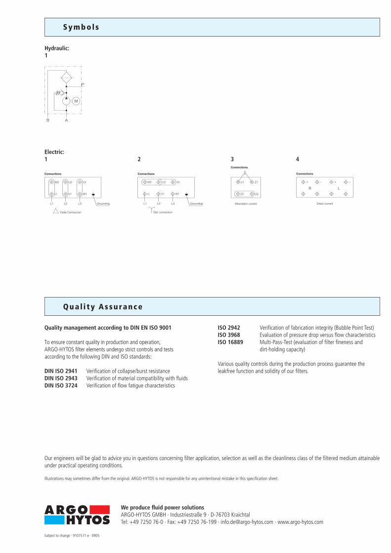
Symbol s
Qua l i ty Assurance
Hydraulic:1
Electric:1 2 3 4
Grounding
Delta Connection
Connections
Grounding
Star connection
Connections
Direct current
Connections
Alternation current
Connections
1/8
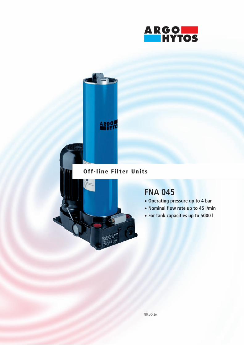
80.50-2e
FNA 045· Operating pressure up to 4 bar
· Nominal flow rate up to 45 l/min
· For tank capacities up to 5000 l
Off - l i ne F i l te r Un i t s
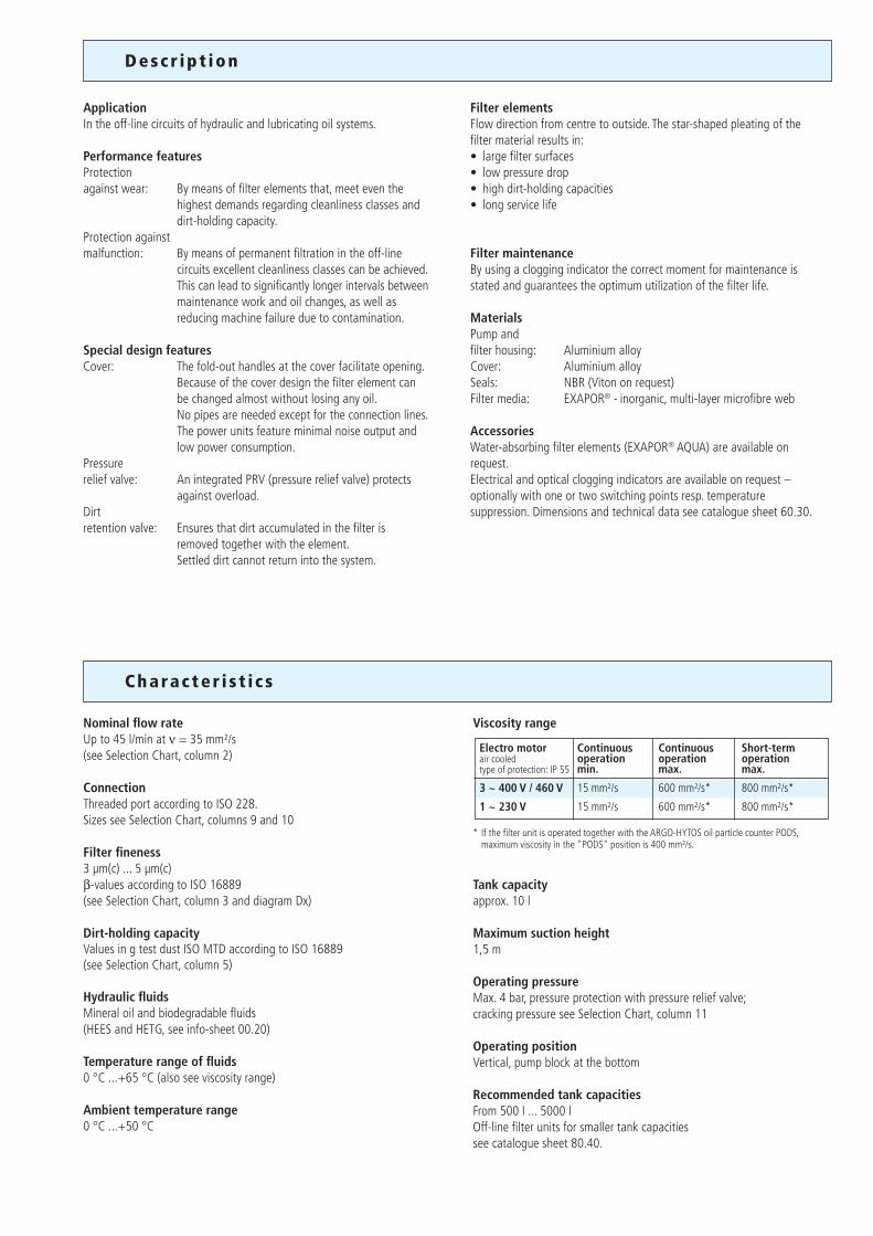
Descr ip t ion
ApplicationIn the off-line circuits of hydraulic and lubricating oil systems.
Performance featuresProtectionagainst wear: By means of filter elements that, meet even the
highest demands regarding cleanliness classes and dirt-holding capacity.
Protection againstmalfunction: By means of permanent filtration in the off-line
circuits excellent cleanliness classes can be achieved. This can lead to significantly longer intervals between maintenance work and oil changes, as well as reducing machine failure due to contamination.
Special design featuresCover: The fold-out handles at the cover facilitate opening. Because of the cover design the filter element can be changed almost without losing any oil. No pipes are needed except for the connection lines. The power units feature minimal noise output and low power consumption.Pressure relief valve: An integrated PRV (pressure relief valve) protects against overload.Dirt retention valve: Ensures that dirt accumulated in the filter is
removed together with the element. Settled dirt cannot return into the system.
Filter elementsFlow direction from centre to outside. The star-shaped pleating of the filter material results in:• large filter surfaces• low pressure drop• high dirt-holding capacities• long service life
Filter maintenanceBy using a clogging indicator the correct moment for maintenance is stated and guarantees the optimum utilization of the filter life.
MaterialsPump andfilter housing: Aluminium alloyCover: Aluminium alloySeals: NBR (Viton on request)Filter media: EXAPOR® - inorganic, multi-layer microfibre web
AccessoriesWater-absorbing filter elements (EXAPOR® AQUA) are available on request.Electrical and optical clogging indicators are available on request – optionally with one or two switching points resp. temperature suppression. Dimensions and technical data see catalogue sheet 60.30.
Charac ter i s t i c s
Viscosity range
* If the filter unit is operated together with the ARGO-HYTOS oil particle counter PODS, maximum viscosity in the "PODS" position is 400 mm²/s.
Tank capacityapprox. 10 l
Maximum suction height1,5 m
Operating pressureMax. 4 bar, pressure protection with pressure relief valve;cracking pressure see Selection Chart, column 11
Operating positionVertical, pump block at the bottom
Recommended tank capacitiesFrom 500 l ... 5000 lOff-line filter units for smaller tank capacitiessee catalogue sheet 80.40.
Nominal flow rateUp to 45 l/min at ν = 35 mm²/s(see Selection Chart, column 2)
ConnectionThreaded port according to ISO 228.Sizes see Selection Chart, columns 9 and 10
Filter fineness3 µm(c) ... 5 µm(c)β-values according to ISO 16889(see Selection Chart, column 3 and diagram Dx)
Dirt-holding capacityValues in g test dust ISO MTD according to ISO 16889(see Selection Chart, column 5)
Hydraulic fluidsMineral oil and biodegradable fluids(HEES and HETG, see info-sheet 00.20)
Temperature range of fluids0 °C ...+65 °C (also see viscosity range)
Ambient temperature range0 °C ...+50 °C
Electro motor Continuous Continuous Short-termair cooled operation operation operationtype of protection: IP 55 min. max. max.
3 ~ 400 V / 460 V 15 mm²/s 600 mm²/s* 800 mm²/s*
1 ~ 230 V 15 mm²/s 600 mm²/s* 800 mm²/s*
Dx
Diagrams
Filter fineness curves in Selection Chart, column 3
The abbreviations represent the following β-values resp. finenesses:
For EXAPOR®-elements: 3 E-N = β3 (c) = 200 EXAPOR®
5 E-N = β5 (c) = 200 EXAPOR®
12 E = β12 (c) = 200 EXAPOR®
For special applications, finenesses differing from these curves are also available by using special composed filter material.
Filtration ratio β as a function of particle size x obtained by the Multi-Pass-Test according to ISO 16889
Particle size x [µm] (for particles larger than the given particle size x)
Filtr
atio
n ra
tio β
for p
artic
les
> x
µm
Effic
ienc
y [%
]
Filter fi
neness, se
e Diagr. D
x
E-motor operating vo
ltage
Dirt-holding ca
pacity
Nominal flow rate
Part No.
Engine speed
at 50 Hz
E-motor operating fre
quency (max.)
Connection A Inlet
Connection B Outlet
Symbols h
ydraulic
Replacement filter
element
Pa
rt No.
Clogging
in
dicator
Cracking pres
sure of by-p
ass
Symbols e
lectric
E-motor power
1 2 3 4 5 6 7 8 9 10 11 12 13 14 15
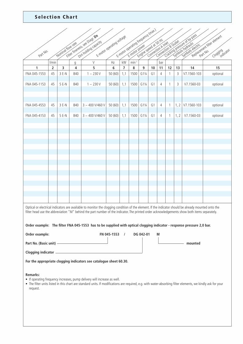
FNA 045-1553 45 3 E-N 840 1 ~ 230 V 50 (60) 1,1 1500 G1¼ G1 4 1 3 V7.1560-103 optional
FNA 045-1153 45 5 E-N 840 1 ~ 230 V 50 (60) 1,1 1500 G1¼ G1 4 1 3 V7.1560-03 optional
FNA 045-4553 45 3 E-N 840 3 ~ 400 V/460 V 50 (60) 1,1 1500 G1¼ G1 4 1 1, 2 V7.1560-103 optional
FNA 045-4153 45 5 E-N 840 3 ~ 400 V/460 V 50 (60) 1,1 1500 G1¼ G1 4 1 1, 2 V7.1560-03 optional
l/min g V Hz kW min-1 bar
Optical or electrical indicators are available to monitor the clogging condition of the element. If the indicator should be already mounted onto the filter head use the abbreviation "M" behind the part number of the indicator. The printed order acknowledgements show both items separately.
Order example: The filter FNA 045-1553 has to be supplied with optical clogging indicator - response pressure 2,0 bar.
Order example: FN 045-1553 / DG 042-01 M
Part No. (Basic unit) mounted Clogging indicator
For the appropriate clogging indicators see catalogue sheet 60.30.
Remarks:• If operating frequency increases, pump delivery will increase as well.• The filter units listed in this chart are standard units. If modifications are required, e.g. with water-absorbing filter elements, we kindly ask for your request.
Se lec t ion Char t
III
II
I
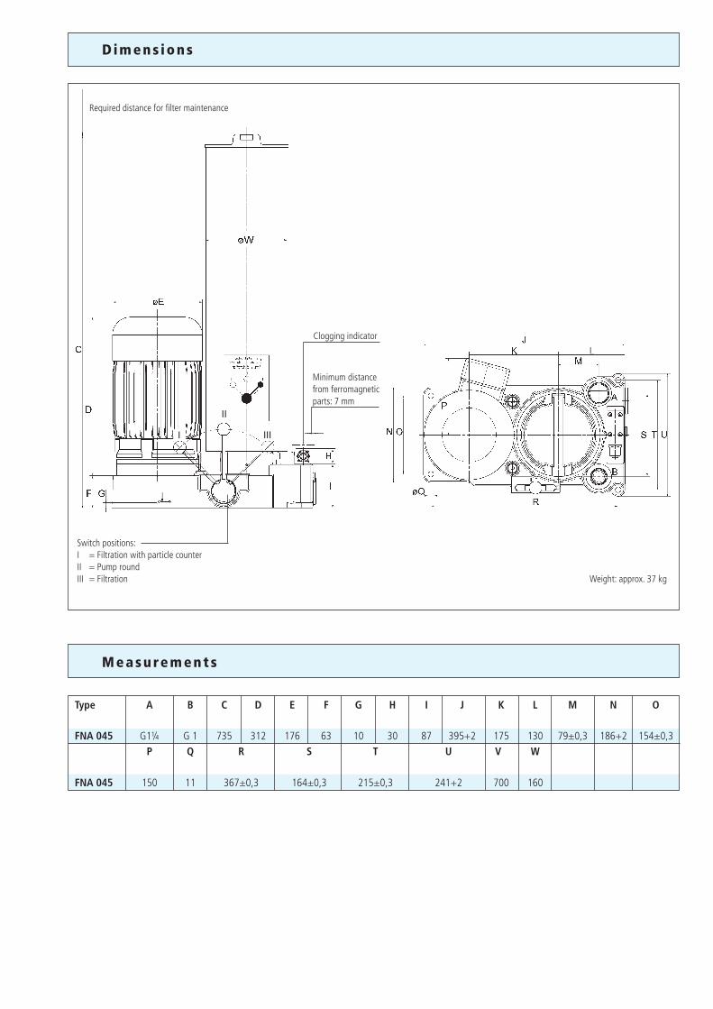
Minimum distance from ferromagnetic parts: 7 mm
Required distance for filter maintenance
Switch positions: I = Filtration with particle counterII = Pump roundIII = Filtration
Clogging indicator
Measurements
Type A B C D E F G H I J K L M N O
FNA 045 G1¼ G 1 735 312 176 63 10 30 87 395+2 175 130 79±0,3 186+2 154±0,3 P Q R S T U V W
FNA 045 150 11 367±0,3 164±0,3 215±0,3 241+2 700 160
Dimens ions
Weight: approx. 37 kg
We produce fluid power solutionsARGO-HYTOS GMBH · Industriestraße 9 · D-76703 KraichtalTel: +49 7250 76-0 · Fax: +49 7250 76-199 · [email protected] · www.argo-hytos.com
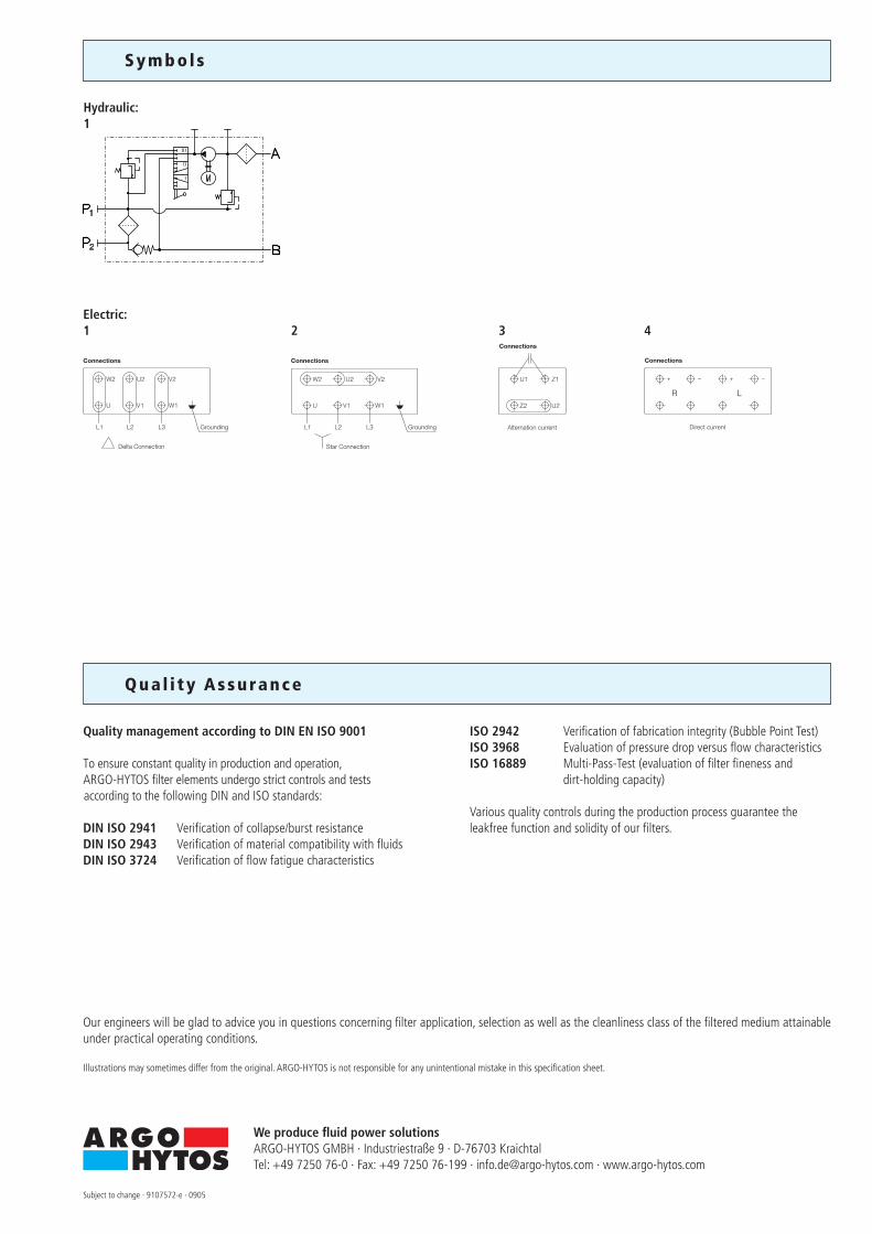
Grounding
Delta Connection
Connections
Grounding
Star Connection
Connections
Direct current
Connections
Alternation current
Connections
Symbol s
Hydraulic:1
Electric:1 2 3 4
Our engineers will be glad to advice you in questions concerning filter application, selection as well as the cleanliness class of the filtered medium attainable under practical operating conditions.
Illustrations may sometimes differ from the original. ARGO-HYTOS is not responsible for any unintentional mistake in this specification sheet.
Subject to change · 9107572-e · 0905
Quality management according to DIN EN ISO 9001
To ensure constant quality in production and operation, ARGO-HYTOS filter elements undergo strict controls and tests according to the following DIN and ISO standards:
DIN ISO 2941 Verification of collapse/burst resistanceDIN ISO 2943 Verification of material compatibility with fluidsDIN ISO 3724 Verification of flow fatigue characteristics
ISO 2942 Verification of fabrication integrity (Bubble Point Test)ISO 3968 Evaluation of pressure drop versus flow characteristicsISO 16889 Multi-Pass-Test (evaluation of filter fineness and dirt-holding capacity)
Various quality controls during the production process guarantee the leakfree function and solidity of our filters.
Qua l i ty Assurance
80.60-1e
FNS 060· With flow control valve
· Operating pressure up to 320 bar
· Nominal flow rate up to 4 l/min
Off - l i ne F i l te rs
Descr ip t ion
Charac ter i s t i c s
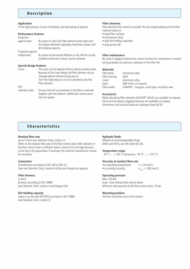
ApplicationIn the high pressure circuits of hydraulic and lubricating oil systems.
Performance featuresProtectionagainst wear: By means of ultra-fine filter elements that meet even
the highest demands regarding cleanliness classes and dirt-holding capacity.
Protection against malfunction: By means of permanent filtration in the off-line circuits
excellent cleanliness classes can be achieved.
Special design featuresCover: The cover can be opened without special auxiliary tools. Because of the cover design the filter element can be
changed almost without losing any oil. From the high-pressure circuit is cleaned by the fine filter element.
Dirt retention valve: Ensures that dirt accumulated in the filter is removed
together with the element. Settled dirt cannot return into the system.
Filter elementsFlow direction from centre to outside. The star-shaped pleating of the filter material results in:• large filter surfaces• low pressure drop• high dirt-holding capacities• long service life
Filter maintenanceBy using a clogging indicator the correct moment for maintenance is stated and guarantees the optimum utilization of the filter life.
MaterialsFilter head: Aluminium alloyFilter housing: SteelCover: Aluminium alloySeals: NBR (Viton on request)Filter media: EXAPOR® - inorganic, multi-layer microfibre web
AccessoriesWater-absorbing filter elements (EXAPOR® AQUA) are available on request.Electrical and optical clogging indicators are available on request. Dimensions and technical data see catalogue sheet 60.20.
Nominal flow rateUp to 4 l/min (see Selection Chart, column 2)Refers to the medium flow rate of the flow control valve. With selection of the flow control valve a sufficient surplus volume from the high-pressure circuit has to be guaranteed. If necessary the machine manufacturer should be consulted.
ConnectionThreaded port according to ISO 228 or DIN 13.Sizes see Selection Chart, column 6 (other port threads on request)
Filter fineness3 µm(c)β-values according to ISO 16889(see Selection Chart, column 4 and diagram Dx)
Dirt-holding capacityValues in g test dust ISO MTD according to ISO 16889(see Selection Chart, column 5)
Hydraulic fluidsMineral oil and biodegradable fluids(HEES and HETG, see info-sheet 00.20)
Temperature range - 30 °C ... + 100 °C (temporary - 40 °C ... + 120 °C)
Viscosity at nominal flow rate • at operating temperature: ν < 35 mm2/s• as starting viscosity: νmax = 1200 mm2/s
Operating pressureMax. 320 bar(max. 5 bar without flow control valve)Minimum inlet pressure at the flow control valve: 10 bar
Mounting position Vertical, connection port at the bottom
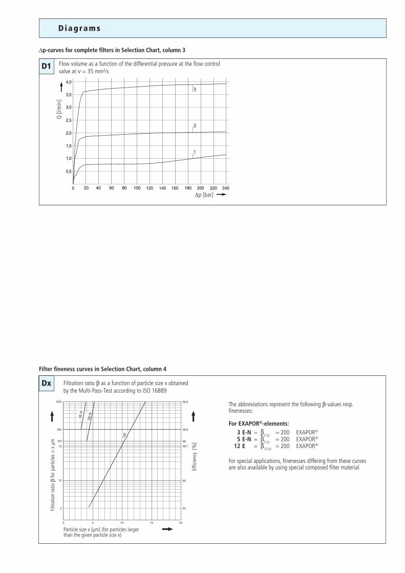
∆p [bar]
Q [l
/min
]D1
Diagrams
The abbreviations represent the following β-values resp. finenesses:
For EXAPOR®-elements: 3 E-N = β3 (c) = 200 EXAPOR®
5 E-N = β5 (c) = 200 EXAPOR®
12 E = β12 (c) = 200 EXAPOR®
For special applications, finenesses differing from these curves are also available by using special composed filter material.
Dx
Filter fineness curves in Selection Chart, column 4
Filtration ratio β as a function of particle size x obtained by the Multi-Pass-Test according to ISO 16889
Particle size x [µm] (for particles larger than the given particle size x)
Filtr
atio
n ra
tio β
for p
artic
les
> x
µm
Effic
ienc
y [%
]
∆p-curves for complete filters in Selection Chart, column 3
Flow volume as a function of the differential pressure at the flow control valve at ν = 35 mm²/s
Cracking pres
sure of by-p
ass
Filter fi
neness se
e Diagr. D
x
Clogging indicator
Pressure d
rop see
diagram D/cu
rve no.
Remarks
Connection A/B
Dirt-holding ca
pacity
Nominal flow rate
Part No.
Replacement filter
element
P
art No.
Symbol
Weight
Flow co
ntrol va
lve
l/min bar kgg
1 2 3 4 5 6 7 8 9 10 11 12 13
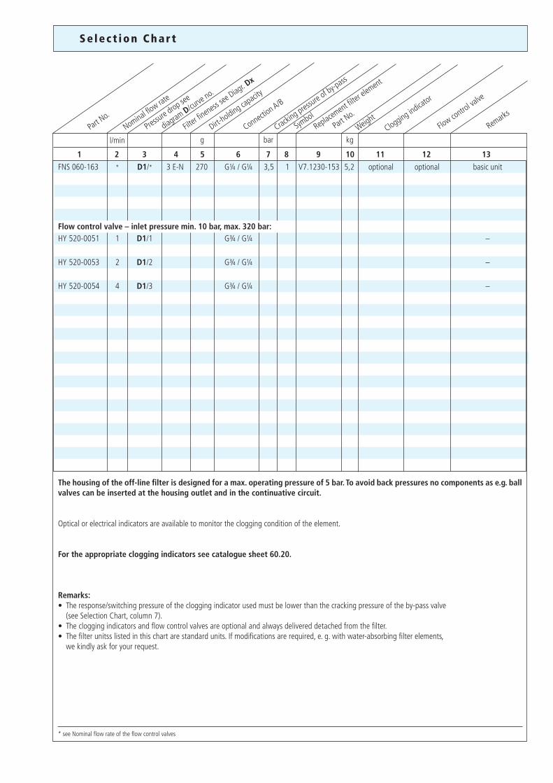
The housing of the off-line filter is designed for a max. operating pressure of 5 bar. To avoid back pressures no components as e.g. ball valves can be inserted at the housing outlet and in the continuative circuit.
Optical or electrical indicators are available to monitor the clogging condition of the element.
For the appropriate clogging indicators see catalogue sheet 60.20.
Remarks:• The response/switching pressure of the clogging indicator used must be lower than the cracking pressure of the by-pass valve (see Selection Chart, column 7). • The clogging indicators and flow control valves are optional and always delivered detached from the filter.• The filter unitss listed in this chart are standard units. If modifications are required, e. g. with water-absorbing filter elements, we kindly ask for your request.
* see Nominal flow rate of the flow control valves
Se lec t ion Char t
FNS 060-163 * D1/* 3 E-N 270 G¼ / G¼ 3,5 1 V7.1230-153 5,2 optional optional basic unit
Flow control valve – inlet pressure min. 10 bar, max. 320 bar:HY 520-0051 1 D1/1 G¾ / G¼ –
HY 520-0053 2 D1/2 G¾ / G¼ –
HY 520-0054 4 D1/3 G¾ / G¼ –
1 2
B
Dimens ions
Measurement
Symbol s
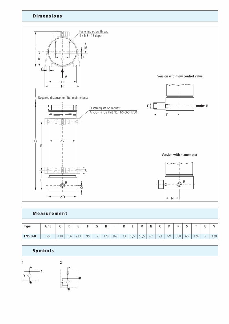
Type A / B C D E F G H I K L M N O P R S T U V
FNS 060 G¼ 410 136 233 95 12 170 169 73 9,5 56,5 67 23 G¾ 300 66 124 9 128
Required distance for filter maintenance
Fastening set on requestARGO-HYTOS Part No. FNS 060.1700
Fastening screw thread4 x M8 - 18 depth
Version with manometer
Version with flow control valve
We produce fluid power solutionsARGO-HYTOS GMBH · Industriestraße 9 · D-76703 KraichtalTel: +49 7250 76-0 · Fax: +49 7250 76-199 · [email protected] · www.argo-hytos.com
1
3
2
4
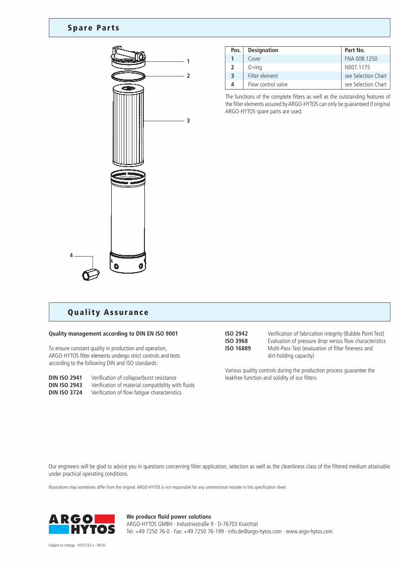
Spare Par t s
Pos. Designation Part No. 1 Cover FNA 008.1250 2 O-ring N007.1175 3 Filter element see Selection Chart 4 Flow control valve see Selection Chart The functions of the complete filters as well as the outstanding features of the filter elements assured by ARGO-HYTOS can only be guaranteed if original ARGO-HYTOS spare parts are used.
Our engineers will be glad to advice you in questions concerning filter application, selection as well as the cleanliness class of the filtered medium attainable under practical operating conditions.
Illustrations may sometimes differ from the original. ARGO-HYTOS is not responsible for any unintentional mistake in this specification sheet.
Subject to change · 9107232-e · 09.05
Quality management according to DIN EN ISO 9001
To ensure constant quality in production and operation, ARGO-HYTOS filter elements undergo strict controls and tests according to the following DIN and ISO standards:
DIN ISO 2941 Verification of collapse/burst resistanceDIN ISO 2943 Verification of material compatibility with fluidsDIN ISO 3724 Verification of flow fatigue characteristics
ISO 2942 Verification of fabrication integrity (Bubble Point Test)ISO 3968 Evaluation of pressure drop versus flow characteristicsISO 16889 Multi-Pass-Test (evaluation of filter fineness and dirt-holding capacity)
Various quality controls during the production process guarantee the leakfree function and solidity of our filters.
Qua l i ty Assurance
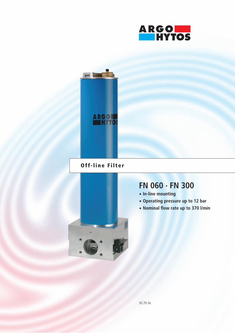
30.70-3e
FN 060 · FN 300· In-line mounting
· Operating pressure up to 12 bar
· Nominal flow rate up to 370 l/min
Off - l i ne F i l te r
Descr ip t ion
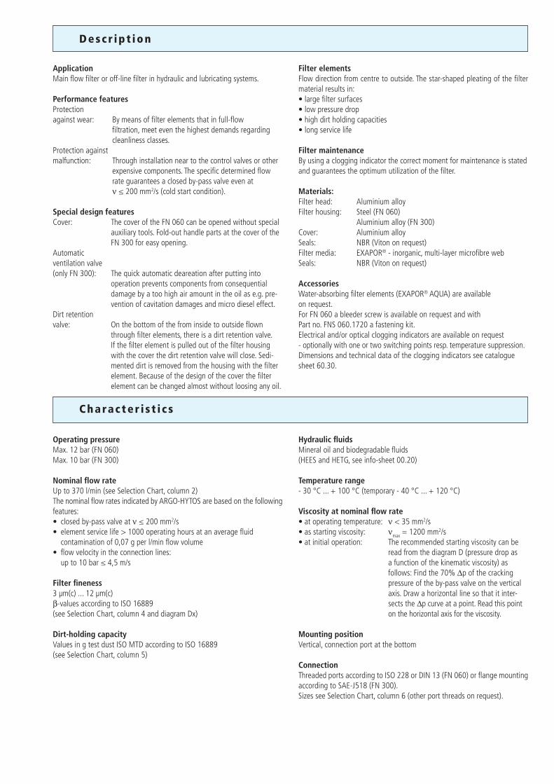
ApplicationMain flow filter or off-line filter in hydraulic and lubricating systems.
Performance featuresProtectionagainst wear: By means of filter elements that in full-flow
filtration, meet even the highest demands regarding cleanliness classes.
Protection againstmalfunction: Through installation near to the control valves or other
expensive components. The specific determined flow rate guarantees a closed by-pass valve even at ν ≤ 200 mm2/s (cold start condition).
Special design featuresCover: The cover of the FN 060 can be opened without special
auxiliary tools. Fold-out handle parts at the cover of the FN 300 for easy opening.
Automatic ventilation valve (only FN 300): The quick automatic deareation after putting into
operation prevents components from consequential damage by a too high air amount in the oil as e.g. pre-vention of cavitation damages and micro diesel effect.
Dirt retention valve: On the bottom of the from inside to outside flown
through filter elements, there is a dirt retention valve. If the filter element is pulled out of the filter housing with the cover the dirt retention valve will close. Sedi-mented dirt is removed from the housing with the filter element. Because of the design of the cover the filter element can be changed almost without loosing any oil.
Filter elementsFlow direction from centre to outside. The star-shaped pleating of the filter material results in:• large filter surfaces• low pressure drop• high dirt holding capacities• long service life
Filter maintenanceBy using a clogging indicator the correct moment for maintenance is stated and guarantees the optimum utilization of the filter.
Materials:Filter head: Aluminium alloyFilter housing: Steel (FN 060) Aluminium alloy (FN 300)Cover: Aluminium alloySeals: NBR (Viton on request)Filter media: EXAPOR® - inorganic, multi-layer microfibre web Seals: NBR (Viton on request)
AccessoriesWater-absorbing filter elements (EXAPOR® AQUA) are available on request. For FN 060 a bleeder screw is available on request and with Part no. FNS 060.1720 a fastening kit.Electrical and/or optical clogging indicators are available on request - optionally with one or two switching points resp. temperature suppression.Dimensions and technical data of the clogging indicators see catalogue sheet 60.30.
Charac ter i s t i c s
Operating pressure Max. 12 bar (FN 060)Max. 10 bar (FN 300)
Nominal flow rate Up to 370 l/min (see Selection Chart, column 2)The nominal flow rates indicated by ARGO-HYTOS are based on the following features:• closed by-pass valve at ν ≤ 200 mm2/s• element service life > 1000 operating hours at an average fluid contamination of 0,07 g per l/min flow volume• flow velocity in the connection lines: up to 10 bar ≤ 4,5 m/s
Filter fineness 3 µm(c) ... 12 µm(c)β-values according to ISO 16889(see Selection Chart, column 4 and diagram Dx)
Dirt-holding capacityValues in g test dust ISO MTD according to ISO 16889(see Selection Chart, column 5)
Hydraulic fluids Mineral oil and biodegradable fluids(HEES and HETG, see info-sheet 00.20)
Temperature range - 30 °C ... + 100 °C (temporary - 40 °C ... + 120 °C)
Viscosity at nominal flow rate • at operating temperature: ν < 35 mm2/s • as starting viscosity: νmax = 1200 mm2/s • at initial operation: The recommended starting viscosity can be
read from the diagram D (pressure drop as a function of the kinematic viscosity) as
follows: Find the 70% ∆p of the cracking pressure of the by-pass valve on the vertical axis. Draw a horizontal line so that it inter- sects the ∆p curve at a point. Read this point on the horizontal axis for the viscosity.
Mounting position Vertical, connection port at the bottom
Connection Threaded ports according to ISO 228 or DIN 13 (FN 060) or flange mounting according to SAE-J518 (FN 300).Sizes see Selection Chart, column 6 (other port threads on request).
D1
D2
∆p [b
ar]
∆p [b
ar]
ν [mm2/s]
ν [mm2/s]Q [l/min]
∆p [b
ar]
Q [l/min]
∆p [b
ar]
Dx
Diagrams
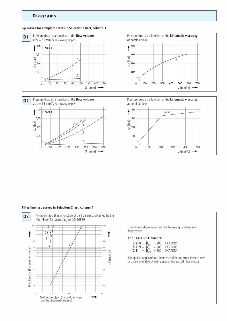
∆p-curves for complete filters in Selection Chart, column 3
Pressure drop as a function of the flow volumeat ν = 35 mm2/s (0 = casing empty)
Pressure drop as a function of the kinematic viscosity at nominal flow
Pressure drop as a function of the flow volumeat ν = 35 mm2/s (0 = casing empty)
Pressure drop as a function of the kinematic viscosity at nominal flow
Filter fineness curves in Selection Chart, column 4
The abbreviations represent the following β-values resp. finenesses:
For EXAPOR®-Elements:
3 E-N = β3 (c) = 200 EXAPOR®
5 E-N = β5 (c) = 200 EXAPOR® 12 E = β12 (c) = 200 EXAPOR®
For special applications, finenesses differing from these curves are also available by using special composed filter media.
Filtration ratio β as a function of particle size x obtained by the Multi-Pass-Test according to ISO 16889
Filtr
atio
n ra
tio β
for p
artic
les
> x
µm
Effic
ienc
y [%
]
Particle size x [µm] (for particles larger than the given particle size x)
Se lec t ion Char t
Cracking pres
sure of by-p
ass
Filter fi
neness se
e diagr. D
x
Clogging indicator
Pressure d
rop see
diagram D/cu
rve no.
Remarks
Connection A/B
Dirt-holding ca
pacity
Nominal flow
Part No.
Replacement filter
element
Pa
rt No.
Symbol
Weight
l/min barg kg
1 2 3 4 5 6 7 8 9 10 11 12
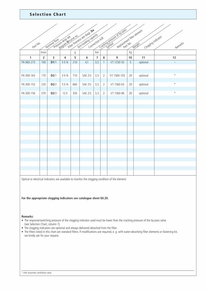
FN 060-273 100 D1/1 5 E-N 210 G1 3,5 1 V7.1230-53 5 optional –
FN 300-163 170 D2/1 3 E-N 710 SAE 2½ 3,5 2 V7.1560-103 20 optional *
FN 300-153 220 D2/2 5 E-N 660 SAE 2½ 3,5 2 V7.1560-03 20 optional *
FN 300-156 370 D2/3 12 E 350 SAE 2½ 3,5 2 V7.1560-06 20 optional *
* with automatic ventilation valve
Optical or electrical indicators are available to monitor the clogging condition of the element.
For the appropriate clogging indicators see catalogue sheet 60.20.
Remarks:• The response/switching pressure of the clogging indicator used must be lower than the cracking pressure of the by-pass valve (see Selection Chart, column 7). • The clogging indicators are optional and always delivered detached from the filter.• The filters listed in this chart are standard filters. If modifications are required, e. g. with water-absorbing filter elements or fastening kit, we kindly ask for your request.
S
1 2
P
P
P
P
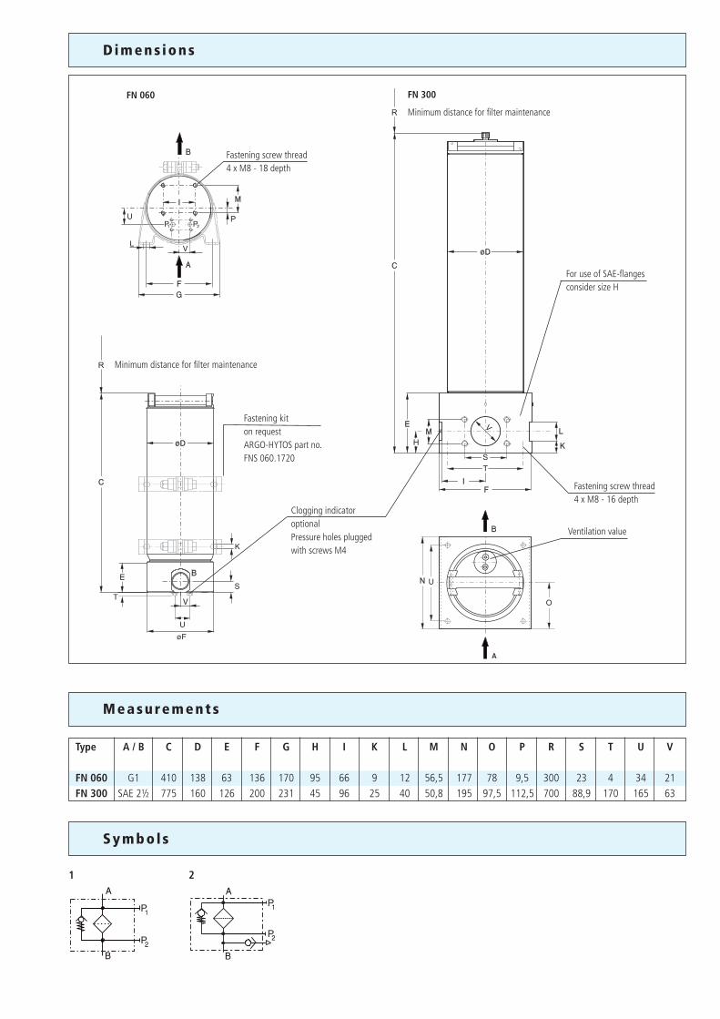
Dimens ions
FN 300
Minimum distance for filter maintenance
FN 060
Measurements
Symbol s
Type A / B C D E F G H I K L M N O P R S T U V
FN 060 G1 410 138 63 136 170 95 66 9 12 56,5 177 78 9,5 300 23 4 34 21FN 300 SAE 2½ 775 160 126 200 231 45 96 25 40 50,8 195 97,5 112,5 700 88,9 170 165 63
Minimum distance for filter maintenance
Fastening kit on requestARGO-HYTOS part no.FNS 060.1720
For use of SAE-flangesconsider size H
Clogging indicatoroptionalPressure holes pluggedwith screws M4
Ventilation value
Fastening screw thread4 x M8 - 16 depth
Fastening screw thread4 x M8 - 18 depth
We produce fluid power solutionsARGO-HYTOS GMBH · Industriestraße 9 · D-76703 KraichtalTel: +49 7250 76-0 · Fax: +49 7250 76-199 · [email protected] · www.argo-hytos.com
1
6
3
2
4
5
Our engineers will be glad to advice you in questions concerning filter application, selection as well as the cleanliness class of the filtered medium attainable under practical operating conditions.
Illustrations may sometimes differ from the original. ARGO-HYTOS is not responsible for any unintentional mistake in this specification sheet.
Subject to change · 9107573-e · 0905
Quality management according to DIN EN ISO 9001
To ensure constant quality in production and operation, ARGO-HYTOS filter elements undergo strict controls and tests according to the following DIN and ISO standards:
DIN ISO 2941 Verification of collapse/burst resistanceDIN ISO 2943 Verification of material compatibility with fluidsDIN ISO 3724 Verification of flow fatigue characteristics
ISO 2942 Verification of fabrication integrity (Bubble Point Test)ISO 3968 Evaluation of pressure drop versus flow characteristicsISO 16889 Multi-Pass-Test (evaluation of filter fineness and dirt-holding capacity)
Various quality controls during the production process guarantee the leakfree function and solidity of our filters.
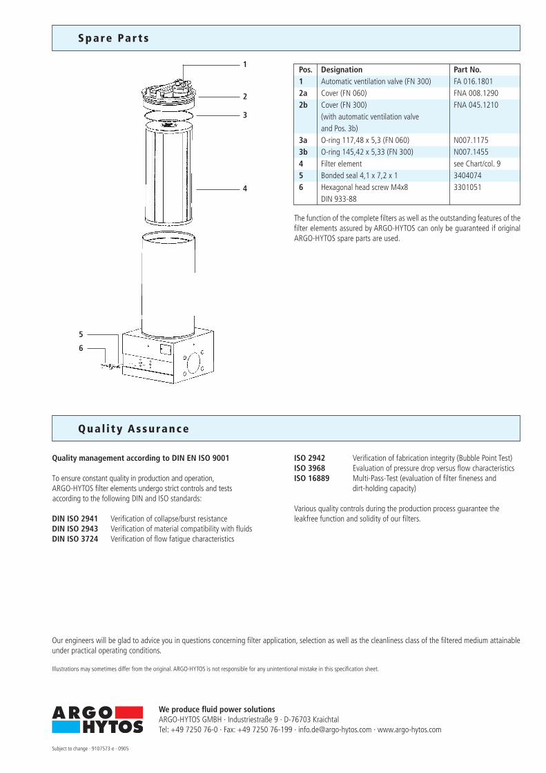
Spare Par t s
Qua l i ty Assurance
The function of the complete filters as well as the outstanding features of the filter elements assured by ARGO-HYTOS can only be guaranteed if original ARGO-HYTOS spare parts are used.
Pos. Designation Part No. 1 Automatic ventilation valve (FN 300) FA 016.1801 2a Cover (FN 060) FNA 008.1290 2b Cover (FN 300) FNA 045.1210 (with automatic ventilation valve and Pos. 3b) 3a O-ring 117,48 x 5,3 (FN 060) N007.1175 3b O-ring 145,42 x 5,33 (FN 300) N007.1455 4 Filter element see Chart/col. 9 5 Bonded seal 4,1 x 7,2 x 1 3404074 6 Hexagonal head screw M4x8 3301051 DIN 933-88
1/8
80.30-1e
FNK 050 · FNK 100· Operating pressure up to 10 bar
· Nominal flow rate up to 125 l/min
· Cooling capacity up to 45 kW
F i l te r Coo l ing Un i t s
Descr ip t ion
Charac ter i s t i c s
ApplicationReturn-flow or off-line filter in hydraulic systems with water cooling.
GeneralHigh power densities in modern hydraulic systems require on one hand excellent cleanliness classes of the oil and on the other hand powerful cooling systems. The ARGO-HYTOS filter cooling unit FNK meets both demands on smallest installation space.
Performance featuresProtection against wear: By means of filter elements that meet even the the highest demands regarding cleanliness classes.
Cooling: Efficient discharge of large heat flow volumes by means of a powerful cooler.
Assembly and operating modeOil that has to be cooled is first cleaned over a fine filter element and then flows – through a check-valve and the high-performance tubular cooler – in cooled-down condition into the tank.Monitoring of filter clogging is effected by an optionally available diffe-rential pressure indicator. The integrated by-pass valve protects the filter element in cold start against increasing diffential pressures.
Special design featuresBy combination of fine filter and cooler in one unit the necessary space is considerably reduced compared to conventional solutions. This also results in less assembling and piping.The filter element is hooked to the cover and is pulled upwards when it has to be changed. Because of the cover design the filter element can be changed almost without losing any oil. An integrated check valve prevents draining of oil from the tank when assembling the filter cooling unit below the oil level.With maintenance work at the cooler it simply can be removed from the housing after removing the water connections.
Filter elementsFlow direction from outside to centre. The star-shaped pleating of the filter results in:• large filter surfaces• low pressure drop• high dirt holding capacities• long service life
Filter maintenanceBy using a clogging indicator the correct moment for maintenance is stated and guarantees the optimum utilization of the filter.The cooler is maintenance-free up to a large extent.Unfavourable water qualities (e.g. high water hardness and PH-value) and high temperatures may lead to sediments in the water pipes and/or the cooler surface. The water quality therefore has to be controlled regularly and if necessary improved. For cleaning of the water pipes the cover of the cooler can be removed. The maintenance instructions give detailed information on the mainte-nance of the cooler.
Materials:Filter housing FNK 050: GG, Filter head: SteelFilter housing FNK 100: Aluminum alloyFilter cover: GGCooler cover: GGCooler catalyst tube: SteelSeals: NBR (Viton on request)Filter media: EXAPOR® – inorganic multi-layer microfibre web
AccessoriesElectrical and optical clogging indicators are available. Dimensions and technical data see catalogue sheet 60.30.
Operating pressureMax. 10 bar
Cooling capacityUp to 45 kW
Nominal flow rateUp to 125 l/min(see Selection Chart, column 3)
Filter fineness5 µm (c) β-values according to ISO 16889(see Selection Chart, column 5 and Diagram Dx)
Dirt-holding capacityValues in g, test dust ISO MTD according to ISO 16889(see Selection Chart, column 6)
Hydraulic fluidsMineral oil and biodegradable fluids(HEES and HETG, see info-sheet 00.20)
Temperature range of fluids-30 °C … +100 °C (temporary -40 °C ... +120 °C)
Mounting positionFilter preferably vertical and/or cooler horizontal
ConnectionThreaded ports according to ISO 228 or DIN 13.Sizes see Selection Chart, column 7.
Se lec t ion Recommendat ions
In principle the filter cooling unit is selected as follows:
1. Selection of the filter cooling unit according to the cooling performance chart
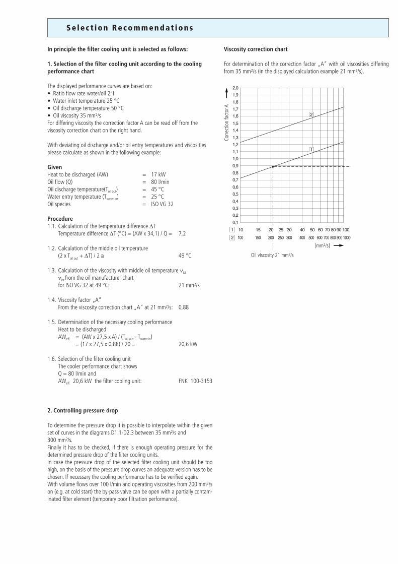
The displayed performance curves are based on:• Ratio flow rate water/oil 2:1• Water inlet temperature 25 °C• Oil discharge temperature 50 °C• Oil viscosity 35 mm²/sFor differing viscosity the correction factor A can be read off from the viscosity correction chart on the right hand.
With deviating oil discharge and/or oil entry temperatures and viscosities please calculate as shown in the following example:
GivenHeat to be discharged (AW) = 17 kWOil flow (Q) = 80 l/minOil discharge temperature(Toil out) = 45 °CWater entry temperature (Twater in) = 25 °COil species = ISO VG 32
Procedure1.1. Calculation of the temperature difference ∆T Temperature difference ∆T (°C) = (AW x 34,1) / Q = 7,2 1.2. Calculation of the middle oil temperature (2 x Toil out + ∆T) / 2 ≅ 49 °C
1.3. Calculation of the viscosity with middle oil temperature νist
νist from the oil manufacturer chart for ISO VG 32 at 49 °C: 21 mm²/s
1.4. Viscosity factor „A“ From the viscosity correction chart „A“ at 21 mm²/s: 0,88
1.5. Determination of the necessary cooling performance Heat to be discharged AWeff. = (AW x 27,5 x A) / (Toil out - Twater in) = (17 x 27,5 x 0,88) / 20 = 20,6 kW
1.6. Selection of the filter cooling unit The cooler performance chart shows Q = 80 l/min and AWeff. 20,6 kW the filter cooling unit: FNK 100-3153
2. Controlling pressure drop
To determine the pressure drop it is possible to interpolate within the given set of curves in the diagrams D1.1-D2.3 between 35 mm²/s and300 mm²/s.Finally it has to be checked, if there is enough operating pressure for the determined pressure drop of the filter cooling units.In case the pressure drop of the selected filter cooling unit should be too high, on the basis of the pressure drop curves an adequate version has to be chosen. If necessary the cooling performance has to be verified again.With volume flows over 100 l/min and operating viscosities from 200 mm²/son (e.g. at cold start) the by-pass valve can be open with a partially contam-inated filter element (temporary poor filtration performance).
Viscosity correction chart
For determination of the correction factor „A“ with oil viscosities differing from 35 mm²/s (in the displayed calculation example 21 mm²/s).
Corre
ctio
n fa
ctor
A
[mm²/s]
Oil viscosity 21 mm²/s
Dk
Diagrams
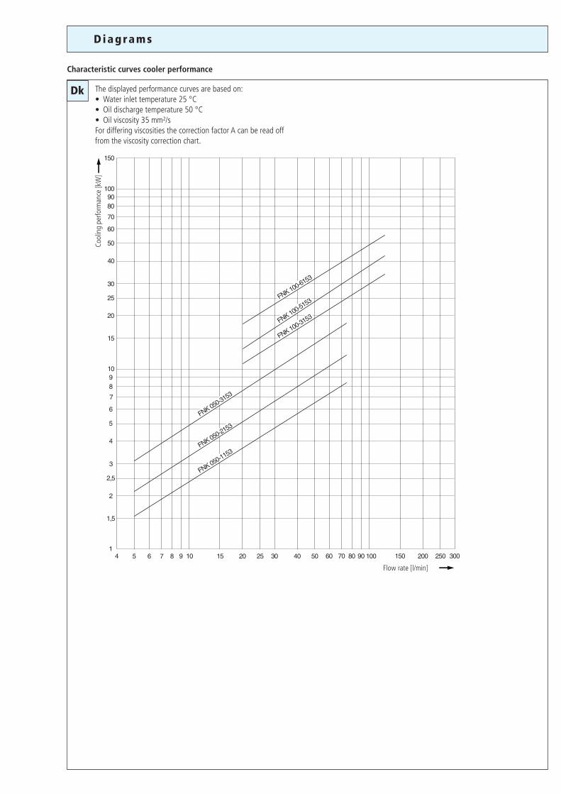
Characteristic curves cooler performance
The displayed performance curves are based on:• Water inlet temperature 25 °C• Oil discharge temperature 50 °C• Oil viscosity 35 mm²/sFor differing viscosities the correction factor A can be read off from the viscosity correction chart.
Flow rate [l/min]
Cool
ing
perfo
rman
ce [k
W]
D1.1
D1.2
D1.3 D2.3
D2.1
D2.2
Dx
∆p [b
ar]
Q [l/min]
∆p [b
ar]
Q [l/min]
∆p [b
ar]
Q [l/min]
∆p [b
ar]
Q [l/min]
∆p [b
ar]
Q [l/min]
∆p [b
ar]
Q [l/min]
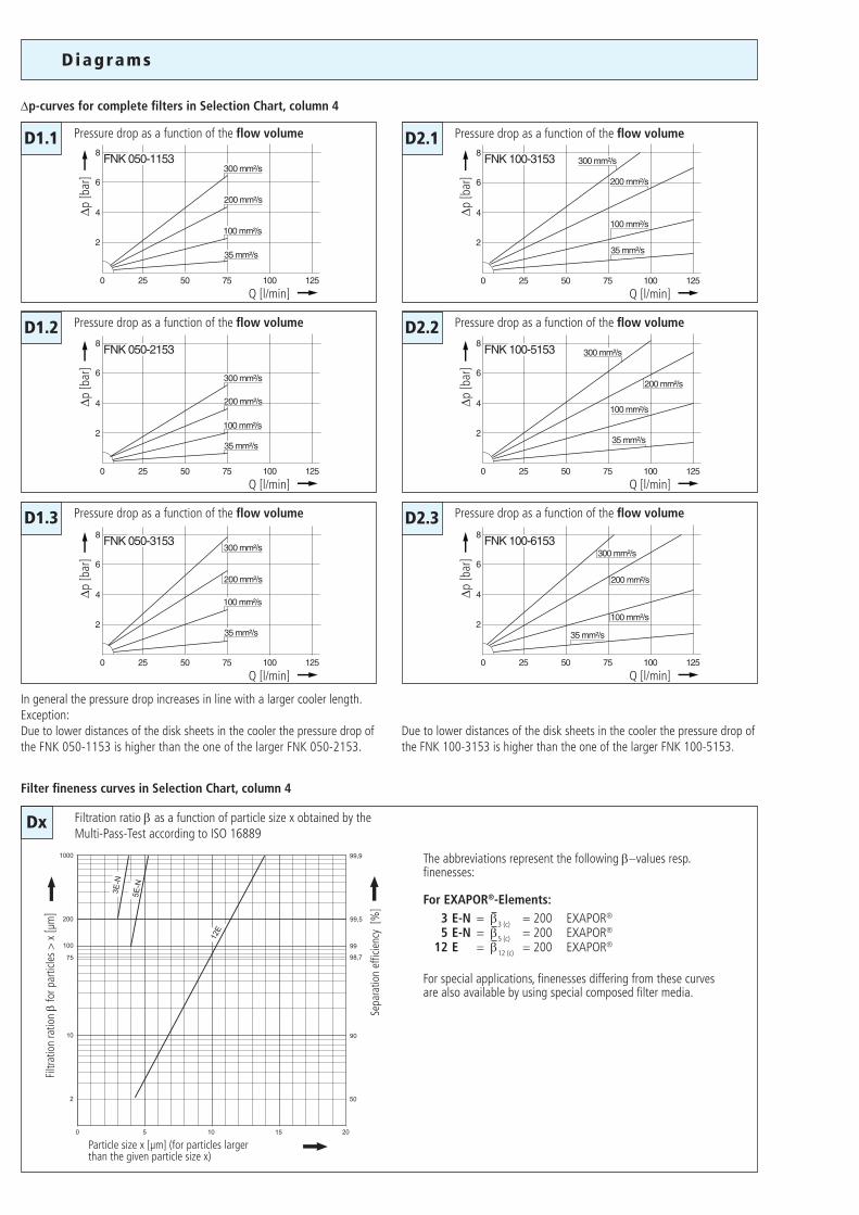
Diagrams
∆p-curves for complete filters in Selection Chart, column 4
Pressure drop as a function of the flow volume
Pressure drop as a function of the flow volume
Pressure drop as a function of the flow volume
Pressure drop as a function of the flow volume
Pressure drop as a function of the flow volume
Pressure drop as a function of the flow volume
Filter fineness curves in Selection Chart, column 4
Filtration ratio β as a function of particle size x obtained by the Multi-Pass-Test according to ISO 16889
Particle size x [µm] (for particles larger than the given particle size x)
Filtr
atio
n ra
tion
β fo
r par
ticle
s >
x [µ
m]
Sepa
ratio
n ef
ficie
ncy
[%]
The abbreviations represent the following β−values resp. finenesses:
For EXAPOR®-Elements: 3 E-N = β3 (c) = 200 EXAPOR®
5 E-N = β5 (c) = 200 EXAPOR®
12 E = β12 (c) = 200 EXAPOR®
For special applications, finenesses differing from these curves are also available by using special composed filter media.
In general the pressure drop increases in line with a larger cooler length.Exception:Due to lower distances of the disk sheets in the cooler the pressure drop of the FNK 050-1153 is higher than the one of the larger FNK 050-2153.
Due to lower distances of the disk sheets in the cooler the pressure drop of the FNK 100-3153 is higher than the one of the larger FNK 100-5153.
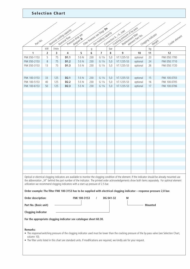
Se lec t ion Char t
Nominal cooling ca
pacity
Part No.
Clogging indicator
Cooler ele
ment
Nominal flow
Replacement filter
el
ement Pa
rt No.
Filter fi
neness se
e Diagr. D
x
1 2 3 4 5 6 7 8 9 10 11 12
kW
FNK 050-1153 5 75 D1.1 5 E-N 230 G 1¼ 5,0 V7.1235-53 optional 23 FNK 050.1700FNK 050-2153 8 75 D1.2 5 E-N 230 G 1¼ 5,0 V7.1235-53 optional 24 FNK 050.1710FNK 050-3153 13 75 D1.3 5 E-N 230 G 1¼ 5,0 V7.1235-53 optional 26 FNK 050.1720 FNK 100-3153 33 125 D2.1 5 E-N 230 G 1¼ 5,0 V7.1235-53 optional 15 FNK 100.0703FNK 100-5153 40 125 D2.2 5 E-N 230 G 1¼ 5,0 V7.1235-53 optional 16 FNK 100.0705FNK 100-6153 50 125 D2.3 5 E-N 230 G 1¼ 5,0 V7.1235-53 optional 17 FNK 100.0706
l/min g bar kgDirt-
holding capacity
Connection A 1
/ A2 inlet
Cracking pres
sure of by-p
ass
Weight
Pressure d
rop see
diagram D
Optical or electrical clogging indicators are available to monitor the clogging condition of the element. If the indicator should be already mounted use the abbreviation „M“ behind the part number of the indicator. The printed order acknowledgements show both items separately. For optimal element utilization we recommend clogging indicators with a start-up pressure of 2.5 bar.
Order example: The filter FNK 100-3153 has to be supplied with electrical clogging indicator – response pressure 2,0 bar.
Order description: FNK 100-3153 / DG 041-32 M
Part No. (Basic unit) Mounted
Clogging indicator
For the appropriate clogging indicator see catalogue sheet 60.30.
Remarks:• The response/switching pressure of the clogging indicator used must be lower than the cracking pressure of the by-pass valve (see Selection Chart, column 10). • The filter units listed in this chart are standard units. If modifications are required, we kindly ask for your request.
1
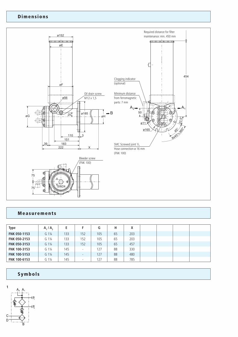
Dimens ions
Measurements
Symbol s
Type A1 / A2 E F G H X
FNK 050-1153 G 1¼ 133 152 105 65 203FNK 050-2153 G 1¼ 133 152 105 65 203FNK 050-3153 G 1¼ 133 152 105 65 457FNK 100-3153 G 1¼ 145 - 127 88 330FNK 100-5153 G 1¼ 145 - 127 88 480FNK 100-6153 G 1¼ 145 - 127 88 785
Required distance for filter maintenance: min. 450 mm
Minimum distance from ferromagnetic parts: 7 mm
Clogging indicator(optional)
Oil drain screwM12 x 1,5
Bleeder screw(FNK 100)
SMC Screwed joint ½,Hose connection-ø 16 mm(FNK 100)
We produce fluid power solutionsARGO-HYTOS GMBH · Industriestraße 9 · D-76703 KraichtalTel: +49 7250 76-0 · Fax: +49 7250 76-199 · [email protected] · www.argo-hytos.com
1
2
3
4
5
Our engineers will be glad to advice you in questions concerning filter application, selection as well as the cleanliness class of the filtered medium attainable under practical operating conditions.
Illustrations may sometimes differ from the original. ARGO-HYTOS is not responsible for any unintentional mistake in this specification sheet.
Subject to change · 13348 · 0309
Quality management according to DIN EN ISO 9001
To ensure constant quality in production and operation,ARGO-HYTOS filter elements undergo strict controls and testsaccording to the following DIN and ISO standards:
DIN ISO 2941 Verification of collapse/burst resistanceDIN ISO 2943 Verification of material compatibility with fluidsDIN ISO 3724 Verification of flow fatigue characteristics
ISO 2942 Verification of fabrication integrity (Bubble Point Test) ISO 3968 Evaluation of pressure drop versus flow characteristics ISO 16889 Multi-Pass-Test (evaluation of filter fineness and dirt-holding capacity)
Various quality controls during the production process guarantee the leakfree function and solidity of our filters.
Qua l i ty Assurance
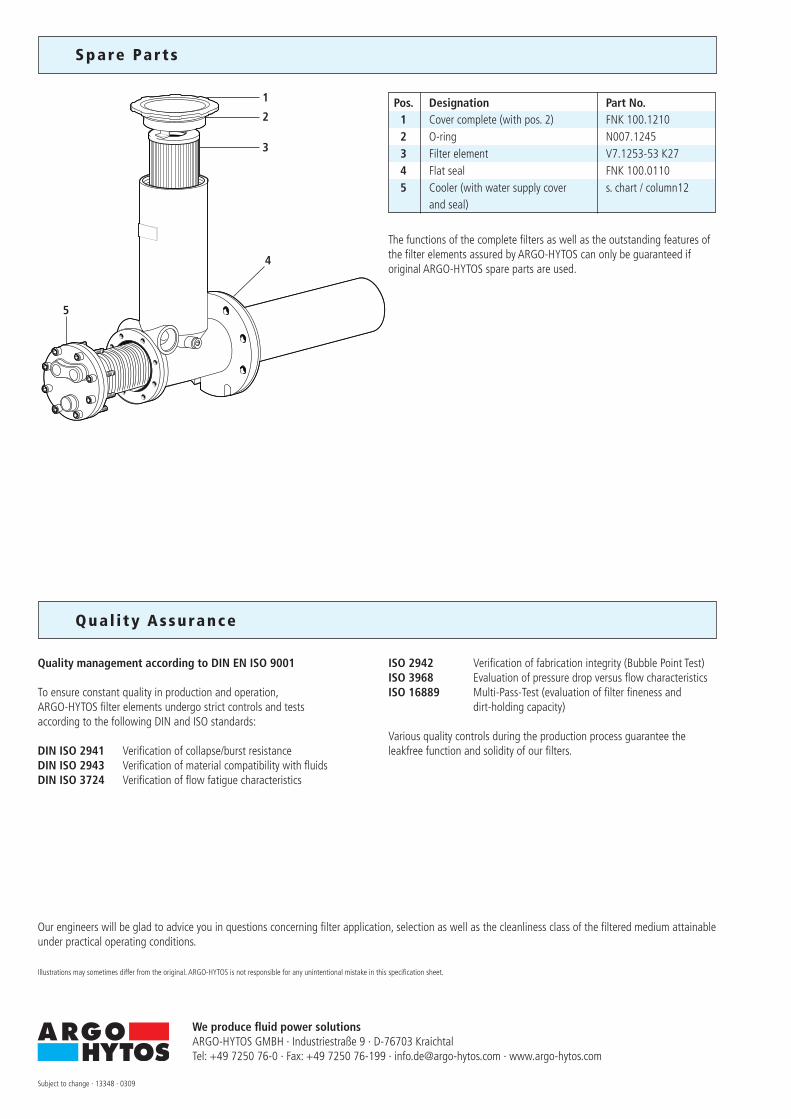
Spare Par t s
Pos. Designation Part No. 1 Cover complete (with pos. 2) FNK 100.1210 2 O-ring N007.1245 3 Filter element V7.1253-53 K27 4 Flat seal FNK 100.0110 5 Cooler (with water supply cover s. chart / column12 and seal)
The functions of the complete filters as well as the outstanding features ofthe filter elements assured by ARGO-HYTOS can only be guaranteed if original ARGO-HYTOS spare parts are used.


