171
Instruction Manual February 2008 LR200 (HART) sitrans

Instruction Manual February 2008
LR200 (HART)sitrans

© Siemens Milltronics Process Instruments Inc. 2008
Safety Guidelines: Warning notices must be observed to ensure personal safety as well as that of others, and to protect the product and the connected equipment. These warning notices are accompanied by a clarification of the level of caution to be observed.
Qualified Personnel: This device/system may only be set up and operated in conjunction with this manual. Qualified personnel are only authorized to install and operate this equipment in accordance with established safety practices and standards.
Unit Repair and Excluded Liability:
• The user is responsible for all changes and repairs made to the device by the user or the user’s agent.
• All new components are to be provided by Siemens Milltronics Process Instruments Inc. • Restrict repair to faulty components only. • Do not reuse faulty components.
Warning: This product can only function properly and safely if it is correctly transported, stored, installed, set up, operated, and maintained.
This product is intended for use in industrial areas.
Note: Always use product in accordance with specifications.
Copyright Siemens Milltronics Process Instruments Inc. 2008. All Rights Reserved
Disclaimer of Liability
This document is available in bound version and in electronic version. We encourage users to purchase authorized bound manuals, or to view electronic versions as designed and authored by Siemens Milltronics Process Instruments Inc. Siemens Milltronics Process Instruments Inc. will not be responsible for the contents of partial or whole reproductions of either bound or electronic versions.
While we have verified the contents of this manual for agreement with the instrumentation described, variations remain possible. Thus we cannot guarantee full agreement. The contents of this manual are regularly reviewed and corrections are included in subsequent editions. We welcome all suggestions for improvement. Technical data subject to change.
MILLTRONICS®is a registered trademark of Siemens Milltronics Process Instruments Inc. Contact SMPI Technical Publications at the following address: Technical Publications Siemens Milltronics Process Instruments Inc. 1954 Technology Drive, P.O. Box 4225 Peterborough, Ontario, Canada, K9J 7B1 Email: [email protected] • For a selection of Siemens Milltronics level measurement manuals, go to:
www. siemens.com/processautomation. Under Process Instrumentation, select Level Measurement and then go to the manual archive listed under the product family.
• For a selection of Siemens Milltronics weighing manuals, go to: www. siemens.com/processautomation. Under Weighing Technology, select Continuous Weighing Systems and then go to the manual archive listed under the product family.

mm
mm
m
Table of Contents
Table of ContentsSafety Notes ...........................................................................................................................................1
Safety marking symbols ............................................................................................................1FCC Conformity ......................................................................................................................................1CE Electromagnetic Compatibility (EMC) Conformity ...................................................................2The Manual ............................................................................................................................................3Technical Support .................................................................................................................................3Abbreviations and Identifications .....................................................................................................4
SITRANS LR200 Overview ................................................................................................5SITRANS LR200 Approvals and Certificates ..................................................................................6
Specifications ....................................................................................................................7Power....................................................................................................................................................... 7Performance .......................................................................................................................................... 7Interface .................................................................................................................................................. 8Mechanical............................................................................................................................................. 9Environmental ........................................................................................................................................ 9Process.................................................................................................................................................. 10Approvals .............................................................................................................................................. 10Programmer (infrared keypad) ........................................................................................................ 11Dimensions: Uni-Construction Polypropylene Rod Antenna ...................................................12
Installation ........................................................................................................................13Mounting location ...............................................................................................................................14
Nozzle design .............................................................................................................................14Nozzle location ..........................................................................................................................14Polarization reference point ...................................................................................................16
Installation Instructions .....................................................................................................................16
Wiring ................................................................................................................................17Power .....................................................................................................................................................17
Connecting SITRANS LR200 ...................................................................................................17Connecting HART ................................................................................................................................18Wiring setups for hazardous area installations ..........................................................................19Instructions specific to hazardous area installations ................................................................23
Operating via the handheld programmer ....................................................................24Activating SITRANS LR200 ...............................................................................................................24
The LCD Display ........................................................................................................................24Handheld Programmer ............................................................................................................25
Programming SITRANS LR200 .........................................................................................................26Programming via the handheld programmer .....................................................................27
Quick Start Wizard via the handheld programmer .....................................................................30Requesting an Echo Profile ..............................................................................................................32Device Address ...................................................................................................................................32Auto False Echo Suppression ..........................................................................................................32Level application example ................................................................................................................33
Operating via SIMATIC PDM .........................................................................................34Functions in SIMATIC PDM ..............................................................................................................34
Features of SIMATIC PDM Rev. 6.0, SP3 ............................................................................34Features of SIMATIC PDM Rev. 5.2, SP1 ............................................................................34
i

mm
mm
m
Tabl
e of
Con
tent
s
Device Description (DD) ....................................................................................................................35Configuring a new device .................................................................................................................35Sensor Calibration ....................................................................................................................35Quick Start Wizard via SIMATIC PDM ..........................................................................................36
Linearization ...............................................................................................................................39Configuring a stillpipe application .........................................................................................42
Changing parameter settings using SIMATIC PDM ...................................................................43Parameters accessed via pull-down menus ......................................................................43
Parameter Reference .....................................................................................................50Pull-down menus via SIMATIC PDM .............................................................................................50Quick Start ............................................................................................................................................51Setup ......................................................................................................................................................51
Device .......................................................................................................................................... 51Input ..............................................................................................................................................52Output ...........................................................................................................................................69Fail-safe .......................................................................................................................................72
Diagnostics ...........................................................................................................................................73Echo Profile................................................................................................................................. 74Measured Values ......................................................................................................................74Remaining Device Lifetime .....................................................................................................75Remaining Sensor Lifetime .....................................................................................................78
Service ...................................................................................................................................................81Device Reset .............................................................................................................................. 81Manufacture Date .....................................................................................................................81LCD Fast Mode ..........................................................................................................................81LCD Contrast ..............................................................................................................................82Powered Hours.......................................................................................................................... 82Memory Test .............................................................................................................................. 82Service Interval.......................................................................................................................... 83Calibration Interval ...................................................................................................................86
Communication ....................................................................................................................................89Device Address ......................................................................................................................... 89Communication Control ...........................................................................................................89
Security .................................................................................................................................................90Lock .............................................................................................................................................. 90Unlock value ...............................................................................................................................90
Language ..............................................................................................................................................91
Notes .................................................................................................................................92
Appendix A: Alphabetical Parameter List ..................................................................93
Appendix B: Troubleshooting .......................................................................................95Communication Troubleshooting ....................................................................................................95Device Status Icons ...........................................................................................................................96General Fault Codes ...........................................................................................................................97Operation Troubleshooting .............................................................................................................102
Appendix C: Maintenance ...........................................................................................104Unit Repair and Excluded Liability ................................................................................................104Replacing the antenna .....................................................................................................................104
Appendix D: Technical Reference .............................................................................105
ii

mm
mm
m
Table of Contents
Principles of Operation ....................................................................................................................105Echo Processing ...............................................................................................................................105Process Intelligence ...............................................................................................................105Time Varying Threshold (TVT) Curves ...............................................................................106Echo Lock ..................................................................................................................................106Echo Position Detection ........................................................................................................107Auto False Echo Suppression ..............................................................................................107
Measurement Range .......................................................................................................................108Near Range ..............................................................................................................................108Far Range ..................................................................................................................................108
Measurement Response .................................................................................................................108mA Output ...........................................................................................................................................108Damping ..............................................................................................................................................109Loss of Echo (LOE) ............................................................................................................................110Fail-safe Mode ...................................................................................................................................110
Fail-safe Timer .........................................................................................................................110Fail-safe value ..........................................................................................................................110
Maximum Process Temperature Chart .......................................................................................111Process Pressure/Temperature derating curves .....................................................................112
PTFE Rod Antenna ANSI Hole Pattern, 150#, ..................................................................113PTFE Rod Antenna DN Hole Pattern, PN161), 2) ...............................................................113PTFE Rod Antenna Threaded Connection ........................................................................114PTFE Rod Antenna Sanitary Connection ...........................................................................114Horn Antenna or Wave Guide – ANSI Hole Pattern, 150# ............................................115Horn Antenna or Wave Guide DN Hole Pattern, PN161) ...............................................115
Loop power .........................................................................................................................................116Typical Connection Drawing ................................................................................................116Curve 1 (General Purpose, Intrinsically Safe, Non-incendive) ....................................116Curve 2 (Flameproof, Increased Safety, Explosion-proof) ............................................117Startup Curve ...........................................................................................................................117
Appendix E: Application Examples ............................................................................118Liquid resin in storage vessel, level measurement ........................................................118Horizontal vessel with volume measurement ..................................................................119Sliding Waveguide on Anaerobic Digesters ....................................................................121Stillpipe Application ................................................................................................................122
Appendix F: HART .........................................................................................................124HART Communication ......................................................................................................................124
SIMATIC PDM ..........................................................................................................................124HART Device Description (DD) ............................................................................................124HART Communicator 375 Menu Structure .......................................................................125
HART Version .....................................................................................................................................127
Appendix G: Flange Adapter Versions ......................................................................128Dimensions: Threaded connection, PTFE Rod ..........................................................................128Dimensions: PTFE Rod Antenna, FF Flange ................................................................................129Dimensions: Threaded Connection, PTFE Rod, Shielded ........................................................130Dimensions: FF Flange with Horn Antenna and Waveguide extension ..............................131Dimensions: FF Flange with Waveguide .....................................................................................133Dimensions: Sliding Waveguide Configuration .........................................................................134Dimensions: Sanitary connection, Rod Antenna, PTFE or HDPE ..........................................135
iii

mm
mm
m
Tabl
e of
Con
tent
s
Dimensions: Flanges ........................................................................................................................136Flange marking ........................................................................................................................138Flange Mounting Instructions ........................................................................................................139
Rod Assembly ..........................................................................................................................140Rod Extension Requirements ...............................................................................................140
Mounting Guidelines ........................................................................................................................141Mounting on a Stillpipe or Bypass Pipe ............................................................................143
Appendix H: ATEX Certificates ...................................................................................144Flameproof/Increased Safety: ATEX Certificate ..............................................................144Intrinsically Safe: ATEX Certificate .....................................................................................148
Appendix J: Firmware Revision History ...................................................................150
Glossary ..........................................................................................................................153
Index ................................................................................................................................157
LCD menu structure ......................................................................................................161
iv

mm
mm
m
SITRAN
S LR200
Safety NotesSpecial attention must be paid to warnings and notes highlighted from the rest of the text
by grey boxes.1)
Safety marking symbols
FCC ConformityUS Installations only: Federal Communications Commission (FCC) rules
WARNING: relates to a caution symbol on the product, and means that failure to observe the necessary precautions can result in death, serious injury, and/or considerable material damage.WARNING 1): means that failure to observe the necessary precautions can result in death, serious injury, and/or considerable material damage.
Note: means important information about the product or that part of the operating manual.
1) This symbol is used when there is no corresponding caution symbol on the prod-uct.
In manual On product Description
Earth (ground) Terminal
Protective Conductor Terminal
(Label on product: yellow background.) WARNING: refer to accompanying documents (manual) for details.
WARNING: Changes or modifications not expressly approved by Siemens Milltronics could void the user’s authority to operate the equipment.
Notes:• This equipment has been tested and found to comply with the limits for a Class A
digital device, pursuant to Part 15 of the FCC Rules. These limits are designed to provide reasonable protection against harmful interference when the equipment is operated in a commercial environment.
• This equipment generates, uses, and can radiate radio frequency energy and, if not installed and used in accordance with the instruction manual, may cause harmful interference to radio communications. Operation of this equipment in a residential area is likely to cause harmful interference to radio communications, in which case the user will be required to correct the interference at his own expense.
7ML19985JP01 SITRANS LR200 (HART) – INSTRUCTION MANUAL Page 1

mm
mm
m
SITR
AN
S LR
200
CE Electromagnetic Compatibility (EMC) ConformityThis equipment has been tested and found to comply with the following EMC Standards:
EMC Standard Title
CISPR 11:2004/EN 55011:1998+A1:1999&A2:2002, CLASS B
Limits and methods of measurements of radio disturbance characteristics of industrial, scientific, and medical (ISM) radio-frequency equipment.
EN 61326:1997+A1:1998+A2:2001+A3:2003 (IEC 61326:2002)
Electrical Equipment for Measurement, Control and Laboratory Use – Electromagnetic Compatibility.
EN61000-4-2:2001 Electromagnetic Compatibility (EMC) Part 4-2:Testing and measurement techniques – Electrostatic discharge immunity test.
EN61000-4-3:2002 Electromagnetic Compatibility (EMC) Part 4-3: Testing and measurement techniques – Radiated, radio-frequency, electromagnetic field immunity test.
EN61000-4-4:2004 Electromagnetic Compatibility (EMC) Part 4-4: Testing and measurement techniques – Electrical fast transient/burst immunity test.
EN61000-4-5:2001 Electromagnetic Compatibility (EMC) Part 4-5: Testing and measurement techniques – Surge immunity test.
EN61000-4-6:2004
Electromagnetic Compatibility (EMC) Part 4-6: Testing and measurement techniques – Immunity to conducted disturbances, induced by radio-frequency fields.
EN61000-4-8:2001 Electromagnetic Compatibility (EMC) Part 4-8:Testing and measurement techniques – Power frequency magnetic field immunity test.
Page 2 SITRANS LR200 (HART) – INSTRUCTION MANUAL 7ML19985JP01
mm
mm
m
SITRAN
S LR200
The Manual
This manual will help you set up your SITRANS LR200 for optimum performance. We always welcome suggestions and comments about manual content, design, and accessibility. Please direct your comments to [email protected].
For other Siemens Milltronics level measurement manuals, go to:www.siemens.com/level and look under Level Measurement.
Application Examples
The application examples used in this manual illustrate typical installations using SITRANS LR200 (see Appendix E: Application Examples on page 118). Because there is often a range of ways to approach an application, other configurations may also apply.
In all examples, substitute your own application details. If the examples do not apply to your application, check the applicable parameter reference for the available options.
Technical SupportSupport is available 24 hours a day.
To find your local Siemens Automation Office address, phone number and fax number go to:
www.siemens.com/automation/partner
• Click on the tab Contacts by Product then drill down to find your product group (+Process Automation > +Process Instrumentation > +Level Measuring Instruments).
• Select the team Technical Support. Click on Next.• Click on the appropriate continent, then select the country followed by the city.
Click on Next.
For on-line technical support go to:
www.siemens.com/automation/support-request
• Enter the device name (SITRANS LR200) or order number, then click on Search, and select the appropriate product type. Click on Next.
• You will be prompted to enter a keyword describing your issue. Then either browse the relevant documentation, or click on Next to email a detailed description of your issue to Siemens Technical Support staff.
Siemens A&D Technical Support Center: phone +49 180 50 50 222
fax +49 180 50 50 223
Notes:• Please follow the installation and operating procedures for a quick, trouble-free
installation and to ensure the maximum accuracy and reliability of your SITRANS LR200.• This manual applies to the SITRANS LR200 (HART) only.
7ML19985JP01 SITRANS LR200 (HART) – INSTRUCTION MANUAL Page 3

mm
mm
m
SITR
AN
S LR
200
Abbreviations and IdentificationsShort form Long Form Description Units
A/D Analog to digital
CE / FM / CSAConformité Européenne / Factory Mutual / Canadian Standards Association
safety approval
Ci Internal capacitance F
D/A Digital to analog
DAC Digital Analog Converter
DCS Distributed Control Systemcontrol room apparatus
dK dielectric constant
HART Highway Addressable Remote Transducer
Ii Input current mA
Io Output current mA
IS Intrinsically Safe safety approval
Li Internal inductance mH
mH milliHenry 10-3 H
µF microFarad 10-6 F
µs microsecond 10-6 s
PED Pressure Equipment Directive safety approval
pF pico Farads 10-12 F
ppm parts per million
PV Primary Variable measured value
SV Secondary Variable equivalent value
TB Transducer Block
TVT Time Varying Thresholdsensitivity threshold
Ui Input voltage V
Uo Output voltage V
Page 4 SITRANS LR200 (HART) – INSTRUCTION MANUAL 7ML19985JP01

mm
mm
m
SITRAN
S LR200
SITRANS LR200 Overview
SITRANS LR200 is a 2-wire, 6 GHz pulse radar level transmitter for continuous monitoring of liquids and slurries in storage and process vessels including high temperature and pressure, to a range of 20 m (66 ft). The instrument consists of an electronic circuit coupled to the antenna and process connection. It is very easy to install and set up, using either the infrared handheld programmer locally, or using SIMATIC PDM from a remote location.
Communication is via HART1). Signals are processed using Sonic Intelligence® which has been field-proven in over 1,000,000 applications worldwide (ultrasonic and radar).
ProgrammingSITRANS LR200 is very easy to install and configure via a graphical local user interface (LUI). You can modify the built in parameters either locally via the Siemens infrared handheld programmer, or from a remote location via SIMATIC PDM.
ApplicationsSITRANS LR200 is designed to measure liquid levels in a variety of applications:
• liquid bulk storage vessels• simple process vessels with gentle agitation• liquids and slurries
1) HART® is a registered trademark of the HART Communication Foundation.
shield length: 100 mm (4"): use for nozzles of 100 mm (4") or less in length
shield length 250 mm (10"): use for long nozzles of 250 mm (10") or less in length
7ML19985JP01 SITRANS LR200 (HART) – INSTRUCTION MANUAL Page 5

mm
mm
m
SITR
AN
S LR
200
SITRANS LR200 Approvals and Certificates
SITRANS LR200 is available in numerous versions, several of which are approved for use in hazardous areas. The approval rating is shown on the device nameplate.
Process Connections
A wide range of process connections and antenna options is available to suit virtually any vessel configuration.
Note: For further details see Approvals on page 10.
Application Type
LR200 Version Approval Rating Valid for: Wiring
Non-hazardous
General Purpose
CSAUS/C, FM, CE N. America, Europe
See page 17
Hazardous
Flameproof ATEX II 1/2 G, EEx dm ia IIC T4 Europe See page 19
Increased Safety
ATEX II 1/2 G, EEx em ia IIC T4 Europe See page 19
Explosion-proof
FM/CSA: Class I, Div. 1, Groups A, B, C, D Class II, Div. 1, Groups E, F, GClass III T4
US/CanadaSee page 20
Non-incendive
FM: Class I, Div. 2, Groups A, B, C, D T5
US See page 20
Intrinsically Safe (barrier required)
FM: Class I, Div. 1, Groups A, B, C, D Class II, Div. 1, Groups E, F, GClass III T4
US
See page 21
ATEX II 1 G, EEx ia IIC T4 Europe
ANZEX Ex ia IIC T4 (Tamb = –40 to +80 oC) IP67
Australia
IECEX TSA 04.0020X T4 International
CSA: Class I, Div. 1, Groups A, B, C, D Class II, Div. 1, Groups E, F, GClass III T4
Canada
Page 6 SITRANS LR200 (HART) – INSTRUCTION MANUAL 7ML19985JP01

mm
mm
m
Specifications
Specifications
Power
• Maximum 30 V DC• 4 to 20 mA• Max startup current see Startup Curve on page 117
PerformanceReference operating conditions according to IEC 60770-1• ambient temperature +15 to +25 °C (+59 to +77 °F)• humidity 45% to 75% relative humidity
• ambient pressure 860 to 1060 mbar g (86000 to 106000 N/m2 g)
Measurement Accuracy (measured in accordance with IEC 60770-1)• Maximum measured error (including hysteresis and non-repeatability)
- From end of antenna to 600mm: 40 mm (1.57”)- Remainder of Range: 10 mm (0.4”) or 0.1% of span (whichever is
greater)
Frequency 5.8 GHz (6.3 GHz in N. America): refer to device nameplate for confirmation
Measurement range1) 20 m (65 ft)
Note: Siemens Milltronics makes every attempt to ensure the accuracy of these specifications but reserves the right to change them at any time.
General Purpose:Non-incendive (FM/US only):Intrinsically Safe:
Nominal 24 V DC at max. 550 Ohm:
Flameproof:Increased Safety:Explosion-proof (FM/CSA US/Canada only):
Nominal 24 V DC at max. 250 Ohm:
1) For the sensor reference point for each configuration, see Dimensions: Uni-Con-struction Polypropylene Rod Antenna on page 12 for the standard version, or Appendix G: Flange Adapter Versions , page 128 onwards for other configura-tions.
7ML19985JP01 SITRANS LR200 (HART) – INSTRUCTION MANUAL Page 7

mm
mm
m
Spec
ifica
tions
Min. detectable distance1)
• 3", 4", and 6" horn2) 300 mm (11.8")• 8" horn 330 mm (12.9")• 100 mm rod antenna 417 mm(16.4")
Update time3) minimum 1 second, depending on settings for Response Rate (2.2.7.1.) and LCD Fast Mode (4.3.)
Influence of ambient temperature • < 0.003%/K (average over full temperature range, referenced to maximum range)
Dielectric constant of material measured• dK > 3 (for < 3 use waveguide antenna or stillpipe)
Memory• non-volatile EEPROM• no battery required
InterfaceAnalog output • signal range 4 to 20 mA (± 0.02 mA accuracy)
upper limit 20 to 20.5 mA, adjustable
• fail signal 3.8 mA to 20.5 mA, or last value
• load Max. 600 Ω; for HART4) communication min. 230 Ω
Communication: HART• Load 230 to 600 Ω, 230 to 500 Ω when connecting a coupling
module• Max. Line Length multi-wire: ≤ 1500 m (4921 ft)• Protocol HART, Version 5.1
Configuration Siemens SIMATIC PDM (PC), or Siemens Milltronics infrared handheld programmer, or HART
handheld communicator
• Display (local)5) graphic LCD, with bar graph representing level
1) Referenced from the end of the antenna. See slso Near Range (2.2.1.11.) on page 53 for more details.
2) 3" and 4" horns should be used only in stillpipe applications.3) Reference conditions: Response Rate (2.2.7.1.) set to FAST, LCD Fast Mode (4.3.)
set to ON.4) HART® is a registered trademark of HART Communication Foundation.5) Display quality will be degraded in temperatures below –25 °C (–13 °F) and above
+65 °C (+149 °F).
Page 8 SITRANS LR200 (HART) – INSTRUCTION MANUAL 7ML19985JP01
mm
mm
m
Specifications
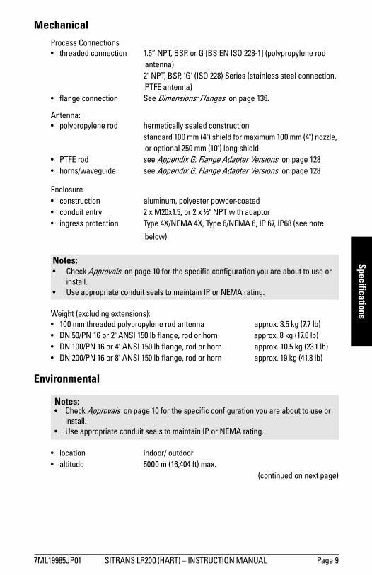
MechanicalProcess Connections• threaded connection 1.5” NPT, BSP, or G [BS EN ISO 228-1] (polypropylene rod
antenna)2" NPT, BSP, 'G' (ISO 228) Series (stainless steel connection, PTFE antenna)
• flange connection See Dimensions: Flanges on page 136.
Antenna:• polypropylene rod hermetically sealed construction standard 100 mm (4") shield for maximum 100 mm (4") nozzle,
or optional 250 mm (10") long shield• PTFE rod see Appendix G: Flange Adapter Versions on page 128• horns/waveguide see Appendix G: Flange Adapter Versions on page 128
Enclosure • construction aluminum, polyester powder-coated• conduit entry 2 x M20x1.5, or 2 x ½" NPT with adaptor• ingress protection Type 4X/NEMA 4X, Type 6/NEMA 6, IP 67, IP68 (see note
below)
Weight (excluding extensions):• 100 mm threaded polypropylene rod antenna approx. 3.5 kg (7.7 lb)• DN 50/PN 16 or 2" ANSI 150 lb flange, rod or horn approx. 8 kg (17.6 lb)• DN 100/PN 16 or 4" ANSI 150 lb flange, rod or horn approx. 10.5 kg (23.1 lb)• DN 200/PN 16 or 8" ANSI 150 lb flange, rod or horn approx. 19 kg (41.8 lb)
Environmental
• location indoor/ outdoor• altitude 5000 m (16,404 ft) max.
(continued on next page)
Notes: • Check Approvals on page 10 for the specific configuration you are about to use or
install.• Use appropriate conduit seals to maintain IP or NEMA rating.
Notes: • Check Approvals on page 10 for the specific configuration you are about to use or
install.• Use appropriate conduit seals to maintain IP or NEMA rating.
7ML19985JP01 SITRANS LR200 (HART) – INSTRUCTION MANUAL Page 9

mm
mm
m
Spec
ifica
tions
• ambient temperature −40 to +80 °C (−40 to +176 °F)• relative humidity suitable for outdoor Type 4X / NEMA 4X, Type 6/NEMA 6, IP67, IP68 enclosure
(see note above)
• installation category I• pollution degree 4
Process• process temperature1) - polypropylene rod −40 to +80 °C (−40 to +176 °F) - PTFE rod or SS horn −40 to +200 °C (−40 to +392 °F)
• pressure (vessel)1) 3 bar, gauge (43.5 psi, gauge)
Approvals
• General CSAUS/C, FM, CE
• Radio Europe (R&TTE), FCC, Industry Canada
• Hazardous Flameproof (Europe)2) ATEX II 1/2 G, EEx dm ia IIC T4Increased Safety (Europe)3) ATEX II 1/2 G, EEx em ia IIC T4
Explosion proof (US/Canada)4) FM/CSA: (barrier not required) Class I, Div. 1, Groups A, B, C, D Class II, Div. 1, Groups E, F, G Class III T4
Non-incendive (US)5) FM: (barrier not required) Class I, Div. 2, Groups A, B, C, D T5
1) The maximum temperature is dependent on the process connection, antenna materials, and vessel pressure. For more detail, or for other configurations, see Maximum Process Temperature Chart on page 111, and Process Pressure/Temperature derating curves on page 112 onwards.
Note: The device nameplate lists the approvals that apply to your device.
2) See Flameproof wiring on page 19.3) See Increased safety wiring on page 19.4) See Explosion-proof wiring (FM/CSA US/Canada only) on page 20.5) See Non-incendive wiring (FM/US only) on page 20.
Page 10 SITRANS LR200 (HART) – INSTRUCTION MANUAL 7ML19985JP01
mm
mm
m
Specifications
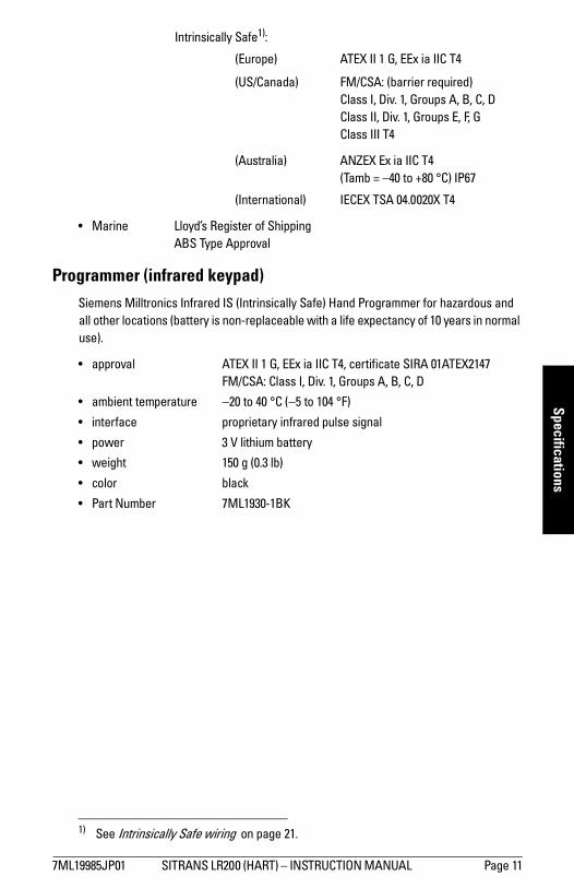
Intrinsically Safe1):(Europe) ATEX II 1 G, EEx ia IIC T4
(US/Canada) FM/CSA: (barrier required) Class I, Div. 1, Groups A, B, C, D Class II, Div. 1, Groups E, F, G Class III T4
(Australia) ANZEX Ex ia IIC T4 (Tamb = –40 to +80 °C) IP67
(International) IECEX TSA 04.0020X T4
• Marine Lloyd’s Register of Shipping ABS Type Approval
Programmer (infrared keypad)Siemens Milltronics Infrared IS (Intrinsically Safe) Hand Programmer for hazardous and all other locations (battery is non-replaceable with a life expectancy of 10 years in normal use).
• approval ATEX II 1 G, EEx ia IIC T4, certificate SIRA 01ATEX2147 FM/CSA: Class I, Div. 1, Groups A, B, C, D
• ambient temperature −20 to 40 °C (−5 to 104 °F)
• interface proprietary infrared pulse signal
• power 3 V lithium battery
• weight 150 g (0.3 lb)
• color black
• Part Number 7ML1930-1BK
1) See Intrinsically Safe wiring on page 21.
7ML19985JP01 SITRANS LR200 (HART) – INSTRUCTION MANUAL Page 11

mm
mm
m
Spec
ifica
tions
Dimensions: Uni-Construction Polypropylene Rod Antenna
1)
1) The shield is the area of the rod which is inactive. The shield length must be longer than the vessel nozzle height.
ref. point
threaded cover
enclosure/electronics
polypropylene rod antenna with integral mounting thread and shield 1)
shield length (internal)std.: 100 mm (4")option:
250 mm (10")
std. 296 mm (11.7") min.option 446 mm (17.6") max.
158 mm (6.2")
154 mm (6.1")
185 mm (7.3")
mounting thread
½" NPT cable entry (or alternatively, M20 cable gland)
process device tag
locking ring
109 mm (4.3")
121 mm (4.8")
50 mm (2.0")
std. 575 mm (22.6") min.option 725 mm (28.5") max.
23 mm (0.9")
Page 12 SITRANS LR200 (HART) – INSTRUCTION MANUAL 7ML19985JP01

mm
mm
m
Installation
Installation
1)
WARNINGS: • Handle the device using the enclosure, not the antenna, to avoid
damage.• Installation shall only be performed by qualified personnel and in
accordance with local governing regulations.• SITRANS LR200 is to be used only in the manner outlined in this
manual, otherwise protection provided by the device may be impaired.• Never attempt to loosen, remove, or disassemble process connection
or instrument housing while vessel contents are under pressure.• This product is designated as a Pressure Accessory per Directive
97/23/EC and is not intended for use as a safety device.• Materials of construction are chosen based on their chemical
compatibility (or inertness) for general purposes. For exposure to specific environments, check with chemical compatibility charts before installing.
• The user is responsible for the selection of bolting and gasket materials which will fall within the limits of the flange and its intended use and which are suitable for the service conditions.
• Improper installation may result in loss of process pressure.
Notes:• Refer to the device nameplate for approval information.• The Process Device Tag shall remain with the process pressure boundary
assembly1). In the event the instrument package is replaced, the Process Device Tag shall be transferred to the replacement unit.
• SITRANS LR200 units are hydrostatically tested, meeting or exceeding the requirements of the ASME Boiler and Pressure Vessel Code and the European Pressure Equipment Directive.
• The serial numbers stamped in each process connection body provide a unique identification number indicating date of manufacture.Example: MMDDYY – XXX (where MM = month, DD = day, YY = year, and
XXX= sequential unit produced) Further markings (space permitting) indicate flange configuration, size, pressure class, material, and material heat code.
1) The process pressure boundary assembly comprises the components that act as a barrier against pressure loss from the process vessel: that is, the combination of process connection body and emitter, but normally excluding the electrical enclosure.
7ML19985JP01 SITRANS LR200 (HART) – INSTRUCTION MANUAL Page 13

mm
mm
m
Inst
alla
tion
Mounting location
Nozzle design
• The end of the shield section should protrude a minimum of 10 mm (0.4”) to avoid false echoes being reflected from the nozzle.
Location on a manhole cover
• A manhole cover is typically a covered nozzle with a diameter 610 mm (24”) or greater.
• For optimum signal conditions, locate the antenna off-center, typically 100 mm (4") from the side.
Nozzle location
Notes: • Correct location is key to a successful application.• Avoid reflective interference from vessel walls and obstructions by following the
guidelines below.
Notes: • For nozzles 100 mm (4") in length or shorter use the 100 mm (4") shield.• For nozzles 250 mm (10") in length or shorter use the 250 mm (10") shield.• For details on other applications, see Appendix G: Flange Adapter Versions on page
128.
WARNING: For vessels with conical or parabolic tops, avoid mounting the instrument at the centre. (The concavity of the top can focus echoes into the centre, giving false readings.)
Note: Under certain circumstances, it may be acceptable to mount SITRANS LR200 at the centre of a flat-topped tank: please discuss this with your Siemens Milltronics Representative.
10 mm (0.4")
locking ring secured by three 2 mm Allen set-screwsthreaded connection
shield
100 mm (4")
Coni
Fl at
Flat Parabolic Conicalpreferred
undesirable
• Avoid central locations on vessels
Page 14 SITRANS LR200 (HART) – INSTRUCTION MANUAL 7ML19985JP01

mm
mm
m
Installation
Nozzle location (continued)• Keep emission cone free of
interference from ladders, pipes, I-beams or filling streams.
• Locate the antenna away from the side wall, to avoid interference from indirect echoes.
• Make allowance for the emission cone spreading: allow a minimum of 300 mm (1 ft) for every 3 m (10 ft) of vessel height.
• Provide easy access for viewing the display and programming via the hand programmer.
• Provide an environment suitable to the housing rating and materials of construction.
• Maintain ambient temperature within –40 to +80 °C (–40 to +176 °F)1).
• Use a sunshield if the instrument will be exposed to direct sunlight.2)
1) For more detail on maximum interface and process temperatures, see Maximum Process Temperature Chart, on page 111.
2) For other configurations, see Maximum Process Temperature Chart on page 111, and the process pressure derating curves beginning on Process Pressure/Temperature derating curves on page 112.
min. 300 mm (1ft) per 3 m (10’) of vessel height
beam angle
20o
emission cone
ambient temperature (surrounding enclosure volume):–40 to 80 °C (–40 to 176 °F)
process temperature(polypropylene rod2) only)–40 to 80 °C (–40 to 176 °F)
handheld programmer
display
7ML19985JP01 SITRANS LR200 (HART) – INSTRUCTION MANUAL Page 15

mm
mm
m
Inst
alla
tion
Polarization reference point• For best results on a tank with
obstructions, or a stillpipe with openings, orient the front or back of the device toward the obstructions
• See Mounting on a Stillpipe or Bypass Pipe on page 143 for more detail.
Installation Instructions
1. Before inserting SITRANS LR200 into its mounting connection, check to ensure the threads are matching, to avoid damaging them.
2. Simply screw SITRANS LR200 into the process connection, and hand tighten. For pressure applications, it will be necessary to use PTFE tape (or other appropriate thread sealing compound) and tighten the process connection beyond hand tight.
The maximum torque is 40 N·m (30 ft.lbs).
3. If you want to rotate the enclosure, use a 2 mm Allen key to loosen the set-screws that secure the locking
ring1).
4. Once the enclosure is in a suitable position, tighten the set-screws.
Notes: • There is no limit to the number of times the device can be rotated. • When mounting, orient the front or back of the device towards the closest wall. For
an illustration of a stillpipe application see Mounting on a Stillpipe or Bypass Pipe on page 143.
• Do not rotate the enclosure after programming and device configuration, otherwise an error may occur, caused by a polarity shift of the transmit pulse.
1) When the locking ring is secured, it prevents the enclosure rotating on the threaded con-nection.
polarization reference point
display
locking ring1) over threaded connection;secured by 32 mm Allen set-screws
Page 16 SITRANS LR200 (HART) – INSTRUCTION MANUAL 7ML19985JP01

mm
mm
m
Wiring
Wiring
Power
Connecting SITRANS LR200
1) 2)
WARNINGS:The DC input terminals shall be supplied from a source providing electrical isolation between the input and output, in order to meet the applicable safety requirements of IEC 61010-1.
All field wiring must have insulation suitable for rated voltages.
WARNINGS: • Check the nameplate on your instrument, to verify the approval rating.• Use appropriate conduit seals to maintain IP or NEMA rating.• Read Instructions specific to hazardous area installations on page 23.Notes: • Use twisted pair cable: AWG 22 to 14 (0.34 mm2 to 2.5 mm2).• Separate cables and conduits may be required to conform to standard
instrumentation wiring practices or electrical codes.
1) May be shipped with the device.2) If cable is routed through conduit, use only approved suitable-size hubs for your
application.
Use a 2 mm Allen key to loosen the lid-lock set screw.
If you want to rotate the enclosure, use the 2 mm Allen key to loosen the locking ring.
locking ring
plug (IP 68)
threaded connection
optionalcable gland1) 2) (or NPT cable entry)2)
7ML19985JP01 SITRANS LR200 (HART) – INSTRUCTION MANUAL Page 17
mm
mm
m
Wirn
g
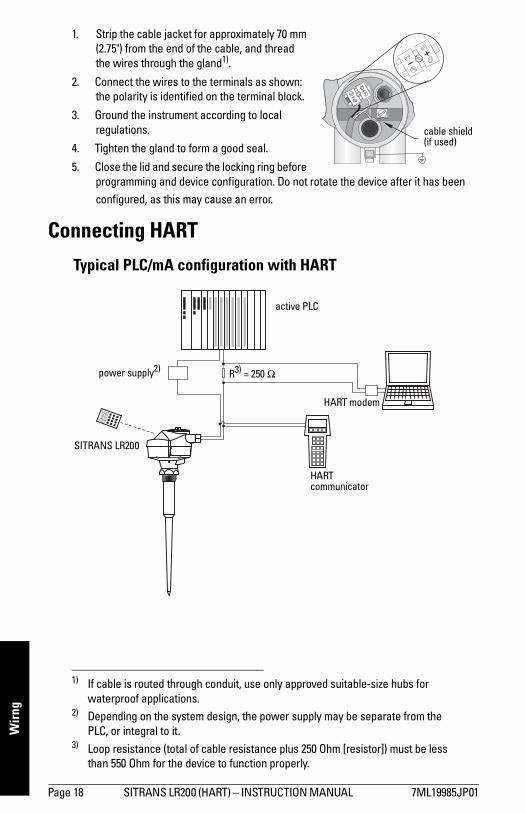
1. Strip the cable jacket for approximately 70 mm(2.75") from the end of the cable, and thread the wires through the gland1).
2. Connect the wires to the terminals as shown: the polarity is identified on the terminal block.
3. Ground the instrument according to local regulations.
4. Tighten the gland to form a good seal.
5. Close the lid and secure the locking ring before programming and device configuration. Do not rotate the device after it has been configured, as this may cause an error.2) 3)
Connecting HART
1) If cable is routed through conduit, use only approved suitable-size hubs for waterproof applications.
2) Depending on the system design, the power supply may be separate from the PLC, or integral to it.
3) Loop resistance (total of cable resistance plus 250 Ohm [resistor]) must be less than 550 Ohm for the device to function properly.
cable shield(if used)
active PLC
HART modem
SITRANS LR200
power supply2)
Typical PLC/mA configuration with HART
R3) = 250 Ω
HART communicator
Page 18 SITRANS LR200 (HART) – INSTRUCTION MANUAL 7ML19985JP01

mm
mm
m
Wiring
Wiring setups for hazardous area installations
There are five wiring options for hazardous area installations. In all cases, check the nameplate on your instrument, and confirm the approval rating.
1. Flameproof wiring
• For power demands see Curve 2 (Flameproof, Increased Safety, Explosion-proof) on page 117.
• For wiring requirements follow local regulations.• See also Instructions specific to hazardous area installations on page 23 and the
ATEX certificate listed above.
2. Increased safety wiring
• For power demands see Curve 2 (Flameproof, Increased Safety, Explosion-proof) on page 117.
• For wiring requirements follow local regulations.• See also Instructions specific to hazardous area installations on page 23 and the
ATEX certificate listed above.
Note: ATEX certificates and connection drawings listed below can be downloaded from the product page of our website at: www.siemens.com/LR200.
Approval Rating Valid for: Reference
ATEX II 1/2 G, EEx dm ia IIC T4 EuropeFlameproof/Increased Safety: ATEX Cer-tificate on page 144.
Approval Rating Valid for: Reference
ATEX II 1/2 G, EEx em ia IIC T4 EuropeFlameproof/Increased Safety: ATEX Certificate on page 144.
Um=250V
HART
EEx dmia IIC T4
II 1/2 G
05ATEX1001XSIRA
Made in Canada
Siemens Milltronics Process Instruments Inc.,Peterborough
7ML1234-56789-0ABC-D
SITRANS LR 200
Encl.: NEMA/TYPE4X, 6, IP67, IP68
Amb.Temp.: – 40 °C to 80 °C
Power Rating: 24V Max., 4 -20mANom., 30 V
Serial No:GYZ /S1034567
Made in Canada
Siemens Milltronics Process Instruments Inc.,Peterborough
7ML1234-56789-0ABC-D
SITRANS LR 200
Encl.: NEMA/TYPE4X, 6, IP67, IP68
Amb.Temp.: – 40 °C to 80 °C
Power Rating: 24V Max., 4 -20mANom., 30 V
Serial No:GYZ /S1034567 Um=250V
HART
EEx emia IIC T4
II 1/2 G
05ATEX1001XSIRA
7ML19985JP01 SITRANS LR200 (HART) – INSTRUCTION MANUAL Page 19

mm
mm
m
Wirn
g
3. Explosion-proof wiring (FM/CSA US/Canada only)
• For power demands see Curve 2 (Flameproof, Increased Safety, Explosion-proof) on page 117.
• For wiring requirements (North America only) see the connection drawing listed above, which can be downloaded from the product page of our website at:www.siemens.com/LR200.
4. Non-incendive wiring (FM/US only)
• For power demands, see Curve 1 (General Purpose, Intrinsically Safe, Non-incendive) on page 116.
• For wiring requirements (North America only) see the connection drawing listed above, which can be downloaded from the product page of our website at: www.siemens.com/LR200.
Approval Rating Valid for: Reference
FM/CSA: Class I, Div. 1, Groups A, B, C, D Class II, Div. 1, Groups E, F, GClass III T4
US/CanadaFM/CSA Explosion Proof Connec-tion Drawing number 23650597
Approval Rating Valid for: Reference
FM: Class I, Div. 2, Groups A, B, C, D T5
USFM Non-Incendive Connection Drawing number 23650537
WARNING: Do Not Remove Cover While Circuits Are Live
FCCID:NJA-LR 200
Temp.Code:T4
erdrawing: 23650597
Class I ;Div1;Group A,B,C,D
Class II ;Div1;Group E,F,G
Class III
P
CANADA: 267P-LR 200
HART
Made in Canada
Siemens Milltronics Process Instruments Inc.,Peterborough
7ML1234-56789-0ABC-D
SITRANSLR200
Encl.:NEMA/TYPE4X,6, IP67, IP68
Amb.Temp.: –40°C to80°C
PowerRating:24V Max., 4 -20mANom.,30V
Serial No: GYZ / S1034567
CANADA:267P-
FCCID:NJA-LR200
Class I,Div.2,Group A,B,C,DTemp.Code:T5
This device complies with Part 15 of the FCC Rules.Operation is subject to the following two conditions1)This device may not cause harmful interference and2)This device must accept any interference received,
including interference that may cause undesired operationMade in Canada
Siemens Milltronics Process Instruments Inc.,Peterborough
7ML1234-56789-0ABC-D
Encl.:NEMA/TYPE4X,6, IP67
Amb.Temp.: –40°C to80°C
Power Rating: 24V Max., 4-20mANom.,30V
Serial No:GYZ /S1034567
Page 20 SITRANS LR200 (HART) – INSTRUCTION MANUAL 7ML19985JP01

mm
mm
m
Wiring
5. Intrinsically Safe wiring
• For power demands see Curve 1 (General Purpose, Intrinsically Safe, Non-incendive) on page 116.
• For wiring requirements: N. America: See the connection drawings listed above, which can be
downloaded from the product page of our website at:www.siemens.com/LR200.
Europe: Follow local regulations.Australia: Follow local regulations.International: Follow local regulations.
• Use appropriate conduit seals to maintain IP or NEMA rating.• Recommended intrinsically safe barriers are listed under Passive Shunt Diode
Barriers on page 22.• Refer to Instructions specific to hazardous area installations on page 23 and the
ATEX certificate listed above.
Approval Rating Valid for: Reference
FM/CSA: Class I, Div. 1, Groups A, B, C, D Class II, Div. 1, Groups E, F, GClass III
US/Canada
FM Intrinsically Safe Connec-tion Drawing number A5E01003040
CSA Intrinsically Safe Connec-tion Drawing number A5E01003039
ATEX II 1 G, EEx ia IIC T4 EuropeIntrinsically Safe: ATEX Certifi-cate on page 148
ANZEX Ex ia IIC T4(Tamb = –40 to 80 °C) IP67
Australia
IECEX TSA 04.0020X International
Note: Selecting a suitable PLC input module, power supply, or barrier requires knowledge about Intrinsic Safety and the application. It is the responsibility of the installer to ensure that the intrinsically safe installation complies with both the apparatus approval requirements and the relevant national code of practice.
RSITRANS LR2007ML1234-56789-0ABC-DSerial No: GYZ / S1034567Encl.: NEMA / TYPE 4X, 6, IP67, IP68Amb.Temp.: – 40 °C to 80 °CPower Rating: 24V Max., 4 - 20mANom.,30V
WARNING: Possible Static Hazard, Do Not Rub Or Clean On SiteMade in Canada
Siemens Milltronics Process Instruments Inc., Peterborough
Class I, Div 1, Group A, B, C, D
Class II, Div 1, Group E, F, G
Class III
HART
Temp. Code: T4
CSA per drawing A5E01003039
FM per drawing A5E01003040
Vmax = 30 V
max = 120 mA
Pmax = 0.8 W
Ci = 15 nF
Li = 0.1 mH
IC: 267P-LR200
FCC ID: NJA-LR200
SITRANS LR200
7ML1234-56789-0ABC-DSerial No: GYZ / S1034567Encl.: NEMA / TYPE 4X, 6, IP67, IP68Amb.Temp.: – 40 °C to 80 °CPower Rating: 24V Max., 4 - 20mANom., 30 V
Made in Canada
Siemens Milltronics Process Instruments Inc., Peterborough
Ui = 30 V
Ii = 120 mA
Pi = 0.8 W
Ci = 15 nF
Li = 0.1 mH
EEx ia IIC T4
SIRA 06ATEX2378X
1 GII
ANZEx 04.3016X
IECEx TSA 04.0020X
Ex ia IIC T4
N117
WARNING: Possible Static Hazard, Do Not Rub Or Clean On Site.
HART 5.8 GHz
7ML19985JP01 SITRANS LR200 (HART) – INSTRUCTION MANUAL Page 21

mm
mm
m
Wirn
g
Passive Shunt Diode Barriers
How to select a passive barrier for SITRANS LR200
To make sure that the barrier safety description is suitable for the LR200 Intrinsically Safe (IS) input parameters, carry out the following calculations:
Re-e = max. end-to-end resistance of the barrierRloop = loop resistance (total of cable resistance plus e.g. sense resistance,
displays, and/or PLC inputs)Vbarrier = value of any non-linear voltage drops due to the barrier
1. Determine the value for Re-e from the data sheet.2. Calculate the total value for Rloop: by adding, for example, sense resistance,
displays, and/or PLC inputs.
3. Calculate Rworking = Re-e + Rloop.
4. Determine the value of Vbarrier from the barrier data sheet (for example, voltage drops due to diodes).
5. Calculate Vworking = Vsupply – Vbarrier.
Use the values for Vworking and Rworking to confirm that operation is within the shaded area of the graph Curve 1 (General Purpose, Intrinsically Safe, Non-incen-dive) on page 116.
Note: A well regulated supply voltage is required.
Manufacturer Part Number
MTL 787SP+ (Dual Channel)
MTL 7787P+ (Dual Channel)
Stahl 9001/01-280-100-10 (Single Channel)
Stahl 9002/01-280-110-10 (Dual Channel)
Notes: • The following list is not exhaustive: there are many IS power supplies and barriers
on the market, which will work with the LR200. • The PLC input modules and barriers listed below have all been tested and are
functionally compatible with the LR200.
Page 22 SITRANS LR200 (HART) – INSTRUCTION MANUAL 7ML19985JP01

mm
mm
m
Wiring
Active barriers (repeating barriers)
Instructions specific to hazardous area installations
(Reference European ATEX Directive 94/9/EC, Annex II, 1/0/6)The following instructions apply to equipment covered by certificate numbers
SIRA 06ATEX2378X, SIRA 05ATEX1001X:
1. For use and assembly, refer to the main instructions.
2. The equipment is certified for use as Category 1G equipment.3. The equipment may be used with flammable gases and vapors with apparatus
group IIC, IIB, and IIA, and temperature classes T1, T2, T3, and T4.4. The equipment is certified for use in an ambient temperature range of –40 °C to
+80 °C.5. The equipment has not been assessed as a safety related device (as referred to by
Directive 94/9/EC Annex II, clause 1.5).6. Installation and inspection of this equipment shall be carried out by suitably trained
personnel in accordance with the applicable code of practice (EN 60079-14 and EN 60079-17 in Europe).
7. The equipment is non-repairable.8. The certificate numbers have an ‘X’ suffix, which indicates that special conditions
for safe use apply. Those installing or inspecting this equipment must have access to the certificates.
9. If the equipment is likely to come into contact with aggressive substances, then it is the responsibility of the user to take suitable precautions that prevent it from being adversely affected, thus ensuring that the type of protection is not compromised.
Aggressive substances: e.g. acidic liquids or gases that may attack metals, or solvents that may affect polymeric materials.
Suitable precautions: e.g. establishing from the material’s data sheet that it is resistant to specific chemicals.
Manufacturer Part Number
MTL 706
MTL 7206
Stahl 9001/51-280-110-14
Pepperl+Fuchs KSD2-CI-S-Ex
Pepperl+Fuchs KFD2-STC3-Ex1
MTL E02009 - verify
MTL E02010
7ML19985JP01 SITRANS LR200 (HART) – INSTRUCTION MANUAL Page 23

mm
mm
m
Qui
ck S
tart
: loc
al
Operating via the handheld programmerSITRANS LR200 carries out its level measurement tasks according to settings made via parameters. The settings can be modified locally via the Local User Interface (LUI) which consists of an LCD display and a handheld programmer.
A Quick Start Wizard provides an easy 5-step guide to help you configure the device for a simple application. There are two ways to access the wizard:
• Quick Start Wizard via the handheld programmer on page 30• Quick Start Wizard via SIMATIC PDM on page 36
For more complex setups see Appendix E: Application Examples on page 118, and for the complete range of parameters see Parameter Reference on page 50.
Activating SITRANS LR200Power up the instrument. SITRANS LR200 automatically starts up in Measurement (RUN)
mode. Press Mode to toggle between Measurement and Program Mode.1)
The LCD Display
Measurement mode (RUN mode)
Normal operation
Fault present
1) In response to a key press request. For details, see Key functions in Measurement mode on page 26.
M[ ]LEVEL
21.40 °C
DATA EXCH.
18.91
1 – toggle indicator for linear units or %2 – selected operation: level, volume, space, or
distance3 – measured value (level or volume, space, or
distance)4 – units5 – bar graph indicates level
6 – secondary region indicates on request1) electronics temperature, echo confidence, loop current, or distance
7 – text area displays status messages 8 – device status indicator678
1 3 42
5
S: 0 LOE7 – text area displays a fault code and an error message8 – service required icon appears
Page 24 SITRANS LR200 (HART) – INSTRUCTION MANUAL 7ML19985JP01

mm
mm
m
Quick Start: local
PROGRAM mode display
Navigation view
• A visible menu bar indicates the menu list is too long to display all items.
• A band halfway down the menu bar indicates the current item is halfway down the list.
• The depth and relative position of the item band on the menu bar indicates the length of the menu list, and approximate position of the current item in the list.
• A deeper band indicates fewer items.
Parameter view
Edit view
Handheld Programmer(Part No. 7ML1930-1BK)
The programmer is ordered separately.
INPUT
VOL CONVERSION
VOLUME BREAKPT
ECHO PROC.
2.2.2
SENSOR CALIB.
current item number
pointer
current item
current menu
menu bar
item band
parameter value/selection
parameter numberLIQUID
MATERIAL
PREVIOUS
NEXT
EDITBACK
2.2.1.2
parameter name
MATERIAL
LIQUID
LIQUID LOW DK
2.2.1.2
C
7ML19985JP01 SITRANS LR200 (HART) – INSTRUCTION MANUAL Page 25

mm
mm
m
Qui
ck S
tart
: loc
al
Key functions in Measurement mode
Programming SITRANS LR200
Change parameter settings and set operating conditions to suit your specific application. • See Operating via SIMATIC PDM on page 34 for remote operation.
Key Function Result
Updates the loop cur-rent. New value is displayed in LCD secondary region.
Updates internal enclosure tempera-ture reading.
New value is displayed in LCD secondary region.
Updates echo confi-dence value. New value is displayed in LCD secondary region.
Updates distance mea-surement. New value is displayed in LCD secondary region.
Mode opens PRO-GRAM mode.
Opens the menu level last displayed in this power cycle, unless power has been cycled since exiting PROGRAM mode or more than 10 minutes have elapsed since PRO-GRAM mode was used. Then top level menu will be displayed.
RIGHT arrowopens PROGRAM mode.
Opens the top level menu.
UP or DOWN arrowtoggles between linear units and percent.
LCD displays measured value in either linear units or per-cent.
Notes: • While the device is in PROGRAM mode the output remains fixed and does not
respond to changes in the device.• Do not use the handheld programmer at the same time as SIMATIC PDM or erratic
operation may result.• SITRANS LR200 automatically returns to Measurement mode after a period of
inactivity in PROGRAM mode (between 15 seconds and 10 minutes, depending on the menu level).
Page 26 SITRANS LR200 (HART) – INSTRUCTION MANUAL 7ML19985JP01

mm
mm
m
Quick Start: local
Programming via the handheld programmer
Parameter menus
Parameters are identified by name and organized into function groups, then arranged in a 5-level menu structure (seeLCD menu structure on page 161).
1. Enter PROGRAM mode• Point the programmer at the display (from a
maximum distance of 300 mm [1 ft.]).
• RIGHT arrow activates PROGRAM
mode and opens menu level 1.
• Mode opens the menu level last
displayed in PROGRAM mode within the last
10 minutes, or menu level 1 if power has
been cycled since then.
Note: For the complete list of parameters with instructions, see Parameter Reference on page 50.
1. QUICK START2. SETUP
2.1. DEVICE2.2. INPUT
2.2.1. SENSOR CALIB.2.2.1.2.MATERIAL
display
handheld programmer (ordered separately)
Max. 300 mm
(1 ft)
7ML19985JP01 SITRANS LR200 (HART) – INSTRUCTION MANUAL Page 27

mm
mm
m
Qui
ck S
tart
: loc
al
2. Navigating: key functions in Navigation mode
3. Editing in PROGRAM mode
Selecting a listed option
a) Navigate to the desired parameter.
b) Press RIGHT arrow to open parameter view.
c) Press RIGHT arrow again to open Edit mode. The current selection is highlighted. Scroll to a new selection.
d) Press RIGHT arrow to accept it
The LCD returns to parameter view and displays the new selection.
Notes: • In Navigation mode ARROW keys move to the next menu item in the direction of the
arrow.
• For Quick Access to parameters via the handheld programmer, press Home ,
then enter the menu number, for example: 2.2.1
Key Name Menu level Function
UP or DOWN arrow
menu or parameter • Scroll to previous or next menu or parameter.
RIGHT arrow
menu• Go to first parameter in the selected menu • or open next menu.
parameter • Open Edit mode.
LEFT arrow menu or parameter • Open parent menu.
Mode menu or parameter • Change to MEASUREMENT mode.
Home menu or parameter • Open top level menu: menu 1.
parameter name
LIQUID
MATERIAL
PREVIOUS
NEXT
EDITBACK
2.2.1.2
MATERIAL
LIQUID
LIQUID LOW DK
2.2.1.2
parameternumber
current selection
Page 28 SITRANS LR200 (HART) – INSTRUCTION MANUAL 7ML19985JP01

mm
mm
m
Quick Start: local
Changing a numeric value
a) Navigate to the desired parameter.
b) Press RIGHT arrow to open parameter view. The current value is displayed.
c) Press RIGHT arrow again to open Edit mode. The current value is highlighted.
d) Key in a new value.
e) Press RIGHT arrow to accept it. The
LCD returns to parameter view and displays
the new selection.
Key functions in Edit mode
Key Name Function
UP or DOWN arrow
Selecting options • Scrolls to item.
Numeric editing
• Increments or decrements digits• Toggles plus/minus sign
RIGHT arrow
Selecting options
• Accepts the data (writes the parameter)• Changes from Edit to Navigation mode
Numeric editing
• Moves cursor one space to the right• or with cursor on Enter sign, accepts the data
and changes from Edit to Navigation mode
LEFT arrow
Selecting options
• Cancels Edit mode without changing the parameter
Numeric editing
• Moves cursor to plus/minus sign if this is the first key pressed
• or moves cursor one space to the left.
Clear Numeric editing • Erases the display.
Decimal point
Numeric editing • Enters a decimal point.
Plus/minus sign
Numeric editing • Changes the sign of the entered value.
to Numeral Numeric
editing • Enters the corresponding character.
M20.00
+20.00
LOW CALIB. 2.2.1.6
20.00 M
LOW CALIB. 2.2.1.6
PREVIOUS
NEXT
EDITBACK
current value
parameternumber
parameter name
C
7ML19985JP01 SITRANS LR200 (HART) – INSTRUCTION MANUAL Page 29

mm
mm
m
Qui
ck S
tart
: loc
al
Quick Start Wizard via the handheld programmer
1. Quick Starta) Point the programmer at the display (from a maximum distance of 300 mm [1 ft.]), then
press RIGHT arrow to activate PROGRAM mode and open menu level 1.
b) Press RIGHT arrow twice to navigate to menu item 1.1 and open parameter view.
c) Press RIGHT arrow to open Edit mode or DOWN arrow to accept default
values and move directly to the next item.
d) To change a setting, scroll to the desired item or key in a new value.
e) After modifying a value, press RIGHT arrow to accept it and press DOWN arrow
to move to the next item.
f) Quick Start settings take effect only after you select Yes to Apply changes in step 1.7.
1.1. Material
1.2. Response RateSets the reaction speed of the device to measurement changes in the target range.
Use a setting just faster than the maximum filling or emptying rate (whichever is greater).
(continued on next page)
Notes: • The Quick Start Wizard settings are inter-related and changes apply only after you
select Yes in Apply? (Apply changes) (1.7.).• Do not use the Quick Start wizard to modify individual parameters: see instead
Parameter Reference on page 50. (Perform customization only after the Quick Start has been completed.)
• Each time the Quick Start Wizard is initiated, the start-up settings are factory defaults. The Wizard will not recall previous user-defined settings.
OptionsLIQUID
LIQUID LOW DK (low dielectric liquid)a)
a) dK < 3.0
OptionsSLOW 0.1 m/minuteMED 1.0 m/minuteFAST 10.0 m/minute
Page 30 SITRANS LR200 (HART) – INSTRUCTION MANUAL 7ML19985JP01

mm
mm
m
Quick Start: local
1.3. Sensor UnitsSelect the units for the Quick Start variables (high and low calibration point, and level, distance, or space)
1.4. Operation
1)
1.5. Low Calibration PointDistance from Sensor Reference to Low Calibration Point: usually process empty level.
1.6. High Calibration PointDistance from Sensor Reference to High Calibration Point: usually process full level.
1.7. Apply? (Apply changes)In order to save the Quick Start settings it is necessary to select Yes to apply changes.
Press Mode to return to Measurement mode. SITRANS LR200 is now ready to operate.
Options M, CM, MM, FT, IN
Operation types
NOSERVICE
The SITRANS LR200 stops updating measurements and asso-ciated loop current. Last valid measurement is displayed.
LEVELDistance to material surface referenced from Low Calibration Point (process empty level).
SPACEDistance to material surface referenced from High Calibration Point (process full level).
DISTANCEDistance to material surface referenced from Sensor Refer-ence Point.
1) The point from which High and Low Calibration points are referenced: see Dimen-sions: Uni-Construction Polypropylene Rod Antenna on page 12 for the standard con-figuration, and Appendix G: Flange Adapter Versions on page 128 for other configurations.
Values Range: 0.00 to 20.00 m
Values Range: 0.00 to 20.00 m
Options YES, NO, DONE (Display shows DONE when Quick Start is successfully completed.)
high calibration point
low calibration point
level
space
distance
sensor reference point1)
7ML19985JP01 SITRANS LR200 (HART) – INSTRUCTION MANUAL Page 31

mm
mm
m
Qui
ck S
tart
: loc
al
Requesting an Echo Profilea) In PROGRAM mode, navigate to: Level Meter
> Diagnostics (3.) > Echo Profile (3.1.)
b) Press RIGHT arrow to request a profile.
c) In the Profile screen, press UP arrow to
select the Transmit icon, and RIGHT arrow
to update the profile.
d) Press DOWN arrow to select the Exit
icon, then RIGHT arrow to return to
previous menu.
Device AddressSets the device address or poll ID on a HART network. Any address other than 0 will cause the output current to be a fixed value, and the current will not indicate the reading.
a) In PROGRAM mode, navigate to: Level Meter > Communication (5.) > Device
Address (5.1.).
b) Press RIGHT arrow , RIGHT arrow , to open parameter view and enable Edit
mode.
c) If required, key in a new value and press RIGHT arrow to accept it. The LCD
displays the new value.
d) Press Mode to return to Measurement mode.
Auto False Echo SuppressionIf SITRANS LR200 displays a false high level, or the reading is fluctuating between the correct level and a false high level, you can use the Auto False Echo Suppression parameters to prevent false echo detection. See TVT (Auto False Echo Suppression) setup (2.2.5.) on page 63 for instructions.
ValuesRange: 0 to 15
Default: 0
DIAGNOSTICS
MEAS. VALUES
REMAIN. DEV. LIFE
RE .MAIN SENS. LIFE
3.1
ECHO PROFILE
C:38 A:TF D:4.25
1 2 3 4 5
transmit icon, selected
exit icon, deselected
transmit icon, deselected
exit icon, selected
Page 32 SITRANS LR200 (HART) – INSTRUCTION MANUAL 7ML19985JP01

mm
mm
m
Quick Start: local
Level application example
Quick Start Setting DescriptionMaterial (1.1.) LIQUIDResponse Rate (1.2.) SLOW Response rate = 0.1 m/minute.Sensor Units (1.3.) mOperation (1.4.) LEVEL Material level referenced from Low Calibration Point.Low Calibration Point (1.5.) 15.5 Process empty level.High Calibration Point (1.6.) 1.0 Process full level.Apply? (Apply changes) (1.7.) YES Save new settings.
Sensor Reference Point
Level
Low Calibration Point
High Cal. Point
15.5 m
1.0 m
SITRANS LR200
The application is a vessel that takes an average 3 hours to fill and 3 weeks to empty. Fill rate = 0.08 m/minute (Low Cal Pt. minus High Cal Pt.) / fastest fill/empty time
= (15.5 m – 1 m) / 180 min. = 14.5 m /180 min. = 0.08 m/min.
14.5
7ML19985JP01 SITRANS LR200 (HART) – INSTRUCTION MANUAL Page 33

mm
mm
m
SIM
ATIC
PD
M
Operating via SIMATIC PDM
SIMATIC PDM is a software package used to commission and maintain SITRANS LR200 and other process devices. Please consult the operating instructions or online help for details on using SIMATIC PDM. (You can find more information at www.fielddevices.com: go to Products and Solutions > Products and Systems > Communications and Software > Process Device Manager.)
Functions in SIMATIC PDM
SIMATIC PDM monitors the process values, alarms and status signals of the device. It allows you to display, compare, adjust, verify, and simulate process device data.
For information on adjusting parameter values and viewing the results, see Changing parameter settings using SIMATIC PDM on page 43 and Parameters accessed via pull-down menus on page 43.
Features of SIMATIC PDM Rev. 6.0, SP3 The graphic interface in SITRANS LR200 makes monitoring and adjustments easy.• The graphic Quick Start Wizard provides an easy 5-step guide to help you configure
the device for a simple application. See Quick Start on page 36 for instructions.• See Display on page 46 to monitor process variables.• See Echo profile on page 46 for easy echo profile comparison.• See Trend on page 47 for Level trend monitoring.• See Auto False Echo Suppression on page 44 and TVT Shaper on page 45 on
adjusting the TVT curve to avoid false echoes.• See Using Linearization via the Quick Start wizard on page 40 for quick setup for
volume measurement in an irregular vessel.• See Simulate AO (Analog Output) on page 49 for simulating a process value during
commissioning/maintenance.
Features of SIMATIC PDM Rev. 5.2, SP1 • SIMATIC PDM Rev. 5.2 SP1 is supported only for basic configuration and
troubleshooting. (For advanced features such as the Quick Start wizard, Rev. 6.0 SP3 or higher is required.)
Note: For a complete list of parameters with instructions, see Parameter Reference on page 50.
Note: While the device is in PROGRAM mode the output remains fixed and does not respond to changes in the device.
Page 34 SITRANS LR200 (HART) – INSTRUCTION MANUAL 7ML19985JP01

mm
mm
m
SIMATIC PD
M
Device Description (DD)You can locate the DD in Device Catalog, under Sensors/Level/Echo/Siemens Milltronics/SITRANS LR200. Check the product page of our website at: www.siemens.com/LR200, under Downloads, to make sure you have the latest version of SIMATIC PDM, the most recent Service Pack (SP) and the most recent hot fix (HF). If you need to install a new DD see Configuring a new device below.
Configuring a new device
1. Check that you have the most recent DD, and if necessary download it from the product page listed under Device Description (DD) above. Save the files to your computer, and extract the zipped file to an easily accessed location. Launch SIMATIC PDM – Manager Device Catalog, browse to the unzipped DD file and select it.
2. Launch SIMATIC Manager and create a new project for LR200. Application Guides for setting up HART devices with SIMATIC PDM can be downloaded from the product page of our website at: www.siemens.com/LR200.
3. Open the Menu Device – Device Reset and click on OK to perform a reset to Factory Defaults.
4. After the reset is complete upload parameters to the PC/PG.
Sensor CalibrationCalibrate the device via the Quick Start wizard.
Note: Clicking on Cancel during an upload from device to SIMATIC PDM will result in some parameters being updated.
7ML19985JP01 SITRANS LR200 (HART) – INSTRUCTION MANUAL Page 35

mm
mm
m
SIM
ATIC
PD
M
Quick Start Wizard via SIMATIC PDMThe graphic Quick Start Wizard provides an easy 5-step guide to help you configure the device for a simple application.
Please consult the operating instructions or online help for details on using SIMATIC PDM. (Application Guides for setting up Siemens HART instruments with SIMATIC PDM are available on our website: www.siemens.com/processautomation.)
1. If you have not already done so, check that you have the most up-to-date Device Description (DD) for your instrument. (See Configuring a new device above.)
2. Launch SIMATIC Manager and create a new project for LR200. Application Guides for setting up HART devices with SIMATIC PDM can be downloaded from the product page of our website at: can be downloaded from the product page of our website at: www.siemens.com/LR200.
3. Configure the device via the Quick Start Wizard.
Quick Start
Launch SIMATIC PDM, open the menu Device – Quick Start, and follow steps 1 to 5.
Notes: • The Quick Start Wizard settings are inter-related and changes apply only after you
click on Transfer at the end of step 5.• Do not use the Quick Start wizard to modify individual parameters: see instead
Parameter Reference on page 50. (Perform customization only after the Quick Start has been completed.)
• Each time the Quick Start Wizard is initiated, the start-up settings are factory defaults. The Wizard will not recall previous user-defined settings.
Quick Start
Page 36 SITRANS LR200 (HART) – INSTRUCTION MANUAL 7ML19985JP01

mm
mm
m
SIMATIC PD
M
Step 1 – Identification
Click NEXT to accept the default values. (Description, Message, and Installation Date
fields can be left blank.)
Step 2 – Application
Select the application type and the material, and click NEXT.
7ML19985JP01 SITRANS LR200 (HART) – INSTRUCTION MANUAL Page 37

mm
mm
m
SIM
ATIC
PD
M
Step 3 – Vessel Shape
The vessel shapes shown are predefined.
To describe a more complex shape see Using Linearization via the Quick Start wizard on page 40.
Select the vessel shape, and click NEXT.
Step 4 – Range
Set the parameters, and click NEXT.
Page 38 SITRANS LR200 (HART) – INSTRUCTION MANUAL 7ML19985JP01

mm
mm
m
SIMATIC PD
M
Step 5 – Summary
Check parameter settings, and click BACK to return and revise values, or TRANSFER to transfer values to the device.
The message Quick Setup was successful will appear. Click on OK then click on OK again to synchronize PDM with the device. (This will take about 2 minutes.)
LinearizationYou can use the linearization feature to define a more complex vessel shape and enter up to 32 level breakpoints where the corresponding volume is known. The values corresponding to 100% and 0% levels must be entered. The breakpoints can be ordered from top to bottom, or the reverse.
4
Breakpoint number
32
1
Break-
point no.
Level
value
(m)
Volume
value
(l)
1 0 0
2 5 500
3 9 3000
4 19.5 8000
Level value
95
0
20 m
0.5
19.5
Example (values are for example purposes only.)
7ML19985JP01 SITRANS LR200 (HART) – INSTRUCTION MANUAL Page 39

mm
mm
m
SIM
ATIC
PD
M
Using Linearization via the Quick Start wizardOpen the menu Device – Quick Start:
1. In Step 1 – Identification, click on Next to accept default values.2. In Step 2 – Application, select a volume application type (for example Volume in a
vessel) and the material, then click on Next.3. In Step 3 – Vessel Shape, choose the vessel shape option Linearization Table and
click on Next.
4. In Step 4 – Range Setup:
a) Enter parameter values.b) Click on Linearization to enter values for the breakpoints.
linearization
Page 40 SITRANS LR200 (HART) – INSTRUCTION MANUAL 7ML19985JP01

mm
mm
m
SIMATIC PD
M
c) In the Linearization window click on the appropriate Breakpoint tab to open thedialog window.
d) Enter the desired level and volume values, and click on OK.
e) In the Step 4 window click on NEXT.
Note: Reset resets values to the values in the offline table.
Breakpoints 1 - 8
7ML19985JP01 SITRANS LR200 (HART) – INSTRUCTION MANUAL Page 41
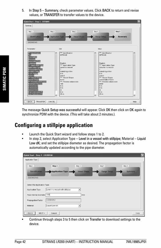
mm
mm
m
SIM
ATIC
PD
M
5. In Step 5 – Summary, check parameter values. Click BACK to return and revisevalues, or TRANSFER to transfer values to the device.
The message Quick Setup was successful will appear. Click OK then click on OK again to synchronize PDM with the device. (This will take about 2 minutes.).
Configuring a stillpipe application• Launch the Quick Start wizard and follow steps 1 to 2. • In step 2, select Application Type – Level in a vessel with stillpipe; Material – Liquid
Low dK; and set the stillpipe diameter as desired. The propagation factor is automatically updated according to the pipe diameter.
• Continue through steps 3 to 5 then click on Transfer to download settings to the device.
Page 42 SITRANS LR200 (HART) – INSTRUCTION MANUAL 7ML19985JP01

mm
mm
m
SIMATIC PD
M
Changing parameter settings using SIMATIC PDM
1. Launch SIMATIC PDM, connect to SITRANS LR200, and upload data from the device.
2. Adjust parameter values in the parameter value field then click on Enter. The status fields read Changed.
3. Open the Device menu, click on Download to device, then use File – Save, to save parameter settings. The status fields are cleared.
Parameters accessed via pull-down menusYou have access to a number of functions via pull-down menus from the menu bar under Device or View.
For a complete list see Pull-down menus via SIMATIC PDM on page 50.
Notes: • For a complete list of parameters, see Parameter Reference on page 50.• Clicking on Cancel during an upload from device to SIMATIC PDM will result in some
parameters being updated.
value fields
pull-down menus
7ML19985JP01 SITRANS LR200 (HART) – INSTRUCTION MANUAL Page 43

mm
mm
m
SIM
ATIC
PD
M
Auto False Echo Suppression
SITRANS LR200 first learns the echo profile. Then the learned profile, or part of it, is used to screen out false echoes. (See Auto False Echo Suppression on page 107 for a more detailed explanation.)
1. Determine Auto Suppression Range (the distance within which the learned TVT will replace the default TVT). Measure the actual distance from the antenna reference point to the material surface using a rope or tape measure, and make allowances for the actual location of the LR200. Subtract 0.5 m (20") from this distance, and use the resulting value.
2. Open the menu Device – Auto False Echo Suppression.
3. Enter the value for Auto Suppression Range and click on Set Range.
4. Click on Learn. While the new curve is being learned all buttons are inaccessible. Unless calculation is instantaneous, buttons may disappear until it is complete.
Notes: • We recommend adjusting Auto False Echo Suppression parameters with an empty
or almost empty vessel.• Set Auto False Echo Suppression and Auto Suppression Range during startup, if
possible.• If the vessel contains an agitator, the agitator should be running. • Before adjusting these parameters, rotate the instrument for best signal (lower
false-echo amplitude).
Page 44 SITRANS LR200 (HART) – INSTRUCTION MANUAL 7ML19985JP01

mm
mm
m
SIMATIC PD
M
5. When buttons are visible, click on Close. Auto TVT is now on, and the learned TVTcurve will be used.
6. To turn Auto False Echo Suppression off or on, reopen menu Device – Auto False Echo Suppression and click on Off or On.
TVT Shaper
This feature allows you to manually adjust the TVT curve to avoid false echoes caused by obstructions. (For an explanation see Auto False Echo Suppression on page 107.)
Open the menu Device – TVT Shaper
• Press Measure to refresh the echo profile and load the current TVT curve from the device.
• Change the position of the cursor on the TVT curve using the Point+ and Point– buttons: raise and lower the curve using Offset+ and Offset–.
• Alternatively, enter values for Point and Offset directly into the dialog boxes.• If desired click on the TVT breakpoints tabs to see settings, then press Transfer to
Device.
Note: Double click on each axis and record the Xscale and Data Scale values, so that you can restore the default view by resetting to these values.
TVT curve
cursor
echo profile
7ML19985JP01 SITRANS LR200 (HART) – INSTRUCTION MANUAL Page 45

mm
mm
m
SIM
ATIC
PD
M
DisplayTo compare outputs in real time open the menu View – Display.
Echo profile
• Open the menu View – Echo Profile• To view a saved profile open the menu View – Show echo profile.•
Note: Double click on each axis and record the Xscale and Data Scale values, so that you can restore the default view by resetting to these values.
delete
save
Page 46 SITRANS LR200 (HART) – INSTRUCTION MANUAL 7ML19985JP01

mm
mm
m
SIMATIC PD
M
Trend
Open the menu View – Trend
MaintenanceFor information on setting maintenance schedules see:• See Remaining Device Lifetime (3.15.) on page 75.• See Remaining Sensor Lifetime (3.16.) on page 78.• See Service Interval (4.16.) on page 83.• See Calibration Interval (4.17.) on page 86.
Self testOpen the menu Device – Self test.
Note: Double click on each axis and record the Xscale and Data Scale values, so that you can restore the default view by resetting to these values.
trend line
7ML19985JP01 SITRANS LR200 (HART) – INSTRUCTION MANUAL Page 47

mm
mm
m
SIM
ATIC
PD
M
Device Reset
Factory Defaults
Use Factory Defaults to reset all parameters excluding device addresses to the default settings.1. Open the menu Device – Device Reset and click on OK to perform a reset to Factory
Defaults.2. After the reset is complete upload parameters to the PC/PG. (If you are performing a
reset after replacing the device with a different instrument, do not upload parameters to the PC/PG).
Configuration Flag ResetTo reset the configuration flag to zero, open the menu Device – Configuration Flag Reset and execute a reset.
Select AnalogOut
Allows you to set the output to Level, Distance, or Space.
If you wish to select Volume, first select a volume application type, and the vessel shape option Linearization Table (see Using Linearization via the Quick Start wizard on page 40).
1. Open the menu Device – Select AnalogOut.2. Inside the window Select AnalogOut a message appears showing the current
setting. Click on OK.3. Select the desired operation type from the pull-down menu. Click on OK.4. Click on OK again to confirm the selection.5. Upload settings from the device.
D/A (Digital/Analog) TrimAllows you to trim the 4 mA and 20 mA points in order to calibrate the mA output.
Open the menu Device – D/A Trim. You will be prompted to attach a calibrated meter and enter the values at 4 mA and at 20 mA.
HART Communication
Allows you to set the number of request/response preambles (minimum 5).
Open the menu Device – HART Communication.
Page 48 SITRANS LR200 (HART) – INSTRUCTION MANUAL 7ML19985JP01

mm
mm
m
SIMATIC PD
M
Simulate AO (Analog Output)Allows you to input a simulated value in order to test the functioning of the mA connections during commissioning or maintenance of the device.
To simulate a user-defined mA value:
1. Open the menu Device – Simulate AO. 2. Select Other, enter the new value, and click on OK. The message ’Field Device
fixed at new value’ appears. Click on OK.3. When you are ready to end simulation, select End and click on OK to return the
device to the original output level.
Device StatusOpen the menu View – Device Status to view Device Status, Extended Diagnostics, Maintenance, and Diagnostics status. See Diagnostics (3.) on page 73 for more detail.
WearReports the number of hours the device has been operating , and the number of times it has been powered up.
Open the menu View – Wear to view:• Powered Days• Power-on Resets
7ML19985JP01 SITRANS LR200 (HART) – INSTRUCTION MANUAL Page 49

mm
mm
m
Para
met
ers
Parameter Reference
Parameters are identified by name and organized into function groups. Menus arranged on up to five levels give access to associated features and options. (See LCD menu structure on page 161 for a chart.)
Parameters accessible via the handheld programmer are preceded by a number. Parameters not preceded by a number are accessible only via SIMATIC PDM.
Some parameters are accessible in SIMATIC PDM via pull-down menus. Where those parameters can also be accessed via the handheld programmer, they are found in the numbered list, and directions for SIMATIC PDM are given beside the individual parameter. Page references for further information can be found under Pull-down menus via SIMATIC PDM below.
Pull-down menus via SIMATIC PDM
Notes: • See Programming via the handheld programmer on page 27 or
Operating via SIMATIC PDM on page 34 for detailed instructions.• In Navigation mode ARROW keys navigate the menu in the
direction of the arrow. • Press RIGHT arrow to open Edit Mode, or to save a modification.• Mode key toggles between PROGRAM and Measurement Modes.
• Default settings in the parameter tables are indicated with an asterisk (*) unless explicitly stated.
• Values shown in the following tables can be entered via the handheld programmer.
Device menus page View menus pageCommunication path Display 46
Download to device
Upload to PC/PG
Update Diagnostic Status
Identification
Trend 47
Echo profile 46
Show Echo Profilea)
Device Status 49
Wear 49
Quick Start 36
Auto False Echo Suppression 44
TVT Shaper 45
Maintenance 47
Self test 47
Device Reset 48
Configuration Flag Reset 48
ToolbarStatus bar
Page 50 SITRANS LR200 (HART) – INSTRUCTION MANUAL 7ML19985JP01

mm
mm
m
Parameters
Quick Start WizardThe Quick Start wizard groups together all the settings you need to configure for a simple application.
• Do not use the Quick Start wizard to modify individual parameters. (Perform customization only after the Quick Start has been completed.)
• Each time the Quick Start Wizard is initiated, the start-up settings are factory defaults. The Wizard will not recall previous user-defined settings.
1. Quick Start
1.1. Material
1.2. Response Rate
1.3. Sensor Units
1.4. Operation
1.5. Low Calibration Point
1.6. High Calibration Point
1.7. Apply? (Apply changes)
2. Setup2.1. Device
2.1.1. Firmware RevisionCorresponds to the software or firmware that is embedded in the SITRANS LR200.
2.1.2. Loader RevisionCorresponds to the software used to update the SITRANS LR200.
2.1.3. Hardware RevisionCorresponds to the electronics hardware of the SITRANS LR200.
Select AnalogOut 48
D/A (Digital/Analog) Trim 48
Simulate AO (Analog Output) 49
Update
HART Communication 48
a) Visible only after an echo profile has been saved.
Note: For detailed instructions see Quick Start Wizard via the handheld programmer on page 30 or Quick Start Wizard via SIMATIC PDM on page 36.
Device menus page View menus (cont’d) page
7ML19985JP01 SITRANS LR200 (HART) – INSTRUCTION MANUAL Page 51
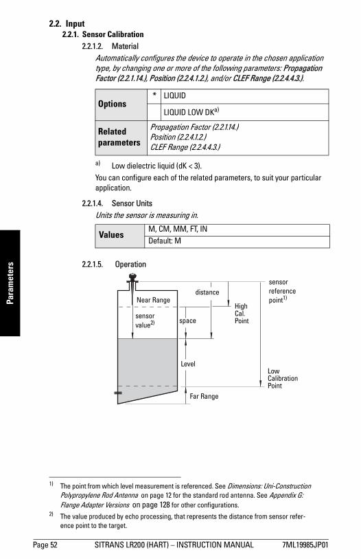
mm
mm
m
Para
met
ers
2.2. Input 2.2.1. Sensor Calibration
2.2.1.2. MaterialAutomatically configures the device to operate in the chosen application type, by changing one or more of the following parameters: Propagation Factor (2.2.1.14.), Position (2.2.4.1.2.), and/or CLEF Range (2.2.4.4.3.).
You can configure each of the related parameters, to suit your particular application.
2.2.1.4. Sensor UnitsUnits the sensor is measuring in.
1) 2)2.2.1.5. Operation
Options* LIQUID
LIQUID LOW DKa)
a) Low dielectric liquid (dK < 3).
Related parameters
Propagation Factor (2.2.1.14.)Position (2.2.4.1.2.)CLEF Range (2.2.4.4.3.)
ValuesM, CM, MM, FT, INDefault: M
1) The point from which level measurement is referenced. See Dimensions: Uni-Construction Polypropylene Rod Antenna on page 12 for the standard rod antenna. See Appendix G: Flange Adapter Versions on page 128 for other configurations.
2) The value produced by echo processing, that represents the distance from sensor refer-ence point to the target.
sensor reference point1)
LevelLow Calibration Point
High Cal. Point
Far Range
sensor value2)
distance
space
Near Range
Page 52 SITRANS LR200 (HART) – INSTRUCTION MANUAL 7ML19985JP01

mm
mm
m
Parameters
2.2.1.6. Low Calibration Pt. Distance from Sensor Reference to Low Calibration Point. Unit is defined in Sensor units.
2.2.1.7. High Calibration Pt. Distance from Sensor Reference to High Calibration Point. Unit is defined in Sensor units.
2.2.1.11. Near RangeThe range in front of the device (measured from the sensor reference point) within which any echoes will be ignored, defined in sensor units. This is sometimes referred to as blanking or a dead zone. The factory set range is dependent on the horn type.
2.2.1.12. Far RangeAllows the material level to drop below Low Calibration Point without generating a Loss of Echo (LOE) state, defined in %. This is sometimes referred to as Range Extension.
Use this feature if the measured surface can drop below the Low Cal. Point in normal operation. Enter value as a percentage of Low Calibration Point.
Options
NO SERVICE
SITRANS LR200 stops updating measurements and associated loop current. Last valid measurement value is displayed.
LEVELDistance to material surface referenced from Low Calibration Point (process empty level).
SPACEDistance to material surface referenced from High Calibration Point (process full level).
DISTANCEDistance to material surface referenced from Sensor Reference Point.
Values Range: 0 to 20 m. Default 20.00 m
Values Range: 0 to 20 m. Default 0.00 m
Values Range: 0 to 20 m (0 to 65.6 ft)
Default: depends on the antenna.See Min. detectable distance on page 8.
Options Range: 0 to 23 m (0 to 75.4 ft) (min. value depends on the setting for Low Calibration Pt. (2.2.1.6.).
Default: Low Calibration Point setting + 1 m (3.2 ft)
7ML19985JP01 SITRANS LR200 (HART) – INSTRUCTION MANUAL Page 53

mm
mm
m
Para
met
ers
2.2.1.14. Propagation Factor
Compensates for the change in microwave velocity from propagation in free space.The value is used to compensate for changes in microwave velocity due to propagation within a metal stillpipe, instead of in free space.
Notes: • When operating with a waveguide antenna or stillpipe, values for the
propagation factor should be set according to the antenna frequency and the antenna/pipe size: see the table below.
• For reliable results the horn size must be close to the pipe size.
5.8 GHz Model
Values Range: 0.3 to 1.5 depending on pipe size.
Default: 1.000
Antenna/Pipe Size (I.D.)a)
a) Since pipe dimensions may vary slightly, the propagation factor may also vary.
50 mm (2”)
80 mm (3”)
100 mm (4”)
150 mm (6”)
200 mm (8”)
Propagation Factor
0.7953 0.9254 0.9530 0.9794 0.9884
6.3 GHz Model
Values Range: 0.3 to 1.5 depending on pipe size.
Default: 1.000
Antenna/Pipe Size (I.D.)a)
a) Since pipe dimensions may vary slightly, the propagation factor may also vary.
50 mm (2”)
80 mm (3”)
100 mm (4”)
150 mm (6”)
200 mm (8”)
Propagation Factor
0.8298 0.9372 0.9603 0.9825 0.9902
Page 54 SITRANS LR200 (HART) – INSTRUCTION MANUAL 7ML19985JP01

mm
mm
m
Parameters
2.2.1.20. Sensor Offset A constant offset that can be added to Sensor value1) to compensate if the sensor has been changed. Units are defined in Sensor Units.
a) Check the material level reported by the device against the actual material level.
b) If necessary adjust Sensor Offset to compensate, until the reading is correct.
2.2.2. Volume conversionCarries out a volume conversion from a level value. 2.2.2.1. Vessel Shape
Defines the vessel shape and allows the LR200 to calculate volume instead of level. If "none" is selected, no volume conversion is performed. Select the vessel shape matching the monitored vessel or reservoir. (Note: Table continues on next page.)
1) See under Operation (2.2.1.5.) on page 52 for an illustration.
ValuesRange: –999999 to 999999
Default: 0 m
Vessel Shape LCD DISPLAY/Description Also required
* NoneNONE/No volume calculation required
N/A
CYLINDER/Flat end horizontal cylinder
maximum volume
SPHERE/Sphere
maximum volume
LINEAR/Upright, linear (flat bottom)
maximum volume
7ML19985JP01 SITRANS LR200 (HART) – INSTRUCTION MANUAL Page 55

mm
mm
m
Para
met
ers
CONICAL BOT/Conical or pyramidal bottom
maximum volume; dimension A
PARABOLIC BOT/Parabolic bottom
maximum volume; dimension A
HALF SPHERE BOT/Half-sphere bottom
maximum volume; dimension A
FLAT SLOPED BOT/Flat sloped bottom
maximum volume; dimension A
PARABOLIC ENDS/Parabolic end horizontal cylinder
maximum volume; dimension A; dimension L
LINEAR TABLE/Linearization table(level/volume breakpoints)
max. volume; level breakpoints; volume breakpoints
Vessel Shape (cont’d)
LCD DISPLAY/Description
Also required (cont’d)
A
A
A
A
A L
Page 56 SITRANS LR200 (HART) – INSTRUCTION MANUAL 7ML19985JP01

mm
mm
m
Parameters
2.2.3. Volume Breakpoints
Enter a value for Maximum Volume, and for dimensions A and L if required. For more complex vessel shapes enter level breakpoints and corresponding volume breakpoints in Table 1-8 (2.2.3.4.) up to Table 25-32 (2.2.3.7.).2.2.3.1. Maximum Volume
The maximum volume of the tank. Enter the numeric value for the vessel volume corresponding to High Calibration Point. The units of volume are not defined in SITRANS LR200, but are understood by the user. For example, if your maximum vessel volume is 8000 L, enter a value of 8000.
2.2.3.2. Dimension AThe height of the vessel bottom in sensor units when the bottom is conical, pyramidal, parabolic, spherical, or flat -sloped. If the vessel is horizontal with parabolic ends, the depth of the end. See Vessel Shape (2.2.2.1.) for an illustration.
2.2.3.3. Dimension LLength of the cylindrical section of a horizontal parabolic end vessel, in sensor units. See Vessel Shape (2.2.2.1.) for an illustration.
Note: Volume breakpoints can be adjusted only after Linearization Table has been selected in Vessel Shape (2.2.2.1.)
ValuesRange: 0 to 999999
Default: 100.0
Related ParametersLow Calibration Pt. (2.2.1.6.)High Calibration Pt. (2.2.1.7.)Vessel Shape (2.2.2.1.)
ValuesRange: 0 to 999999 in units
Default: 0.0
Related Parameters Vessel Shape (2.2.2.1.)
ValuesRange: 0 to 999999 in units
Default: 0.0
Related Parameters Vessel Shape (2.2.2.1.)
7ML19985JP01 SITRANS LR200 (HART) – INSTRUCTION MANUAL Page 57

mm
mm
m
Para
met
ers
2.2.3.4. Table 1-8Volume breakpoints allow you to define a complex vessel shape as a series of segments. A value is assigned to each level breakpoint and a corresponding value is assigned to each volume breakpoint. Level values are defined in sensor units1). Enter the maximum vessel volume 2) in whatever volume units you prefer. Volume units are not explicitly defined in the SITRANS LR200.
Enter up to 32 level breakpoints, where the corresponding volume is known. The values corresponding to 100% and 0% levels must be entered. The breakpoints can be ordered from top to bottom, or the reverse. Breakpoints are grouped into four tables: Table 1-8, Table 9-16, Table 17-24, and Table 25-32.
Entering breakpoints via PDM:
a) Level values are defined in Sensor Units. To change the unit, go to Input > Sensor Calibration > Sensor Units and make a new selection.
b) Go to > Volume conversion and select Linearization Table option.
c) Go to > Volume breakpoints > Table 1-8 and enter values for level and volume breakpoints in table.
d) Repeat step c) till values have been entered for all required breakpoints, using other tables as required.
Entering breakpoints via the handheld programmer:
a) Level values are defined in Sensor Units. To change the unit, go to Input (2.2.) > Sensor Calibration (2.2.1.) > Sensor Units (2.2.1.4.) and make a new selection.
b) Go to Input (2.2.) > Volume conversion (2.2.2.) > Vessel Shape (2.2.2.1.) and select Linearization Table option.
c) Go to the appropriate table for the particular breakpoint you wish to adjust: for example, go to Table 1-8 for breakpoint 1.
d) Under Table 1-8, go to Level 1 (2.2.3.4.1.) to enter the level value for the breakpoint 1.
1) See Sensor Units (2.2.1.4.) on page 52.2) See Maximum Volume (2.2.3.1.) on page 57.
Level Values1)Range: 0 to 99.999 m
Default: 0
Volume Values2)
Range: 0 to 99999
Default: 0
Page 58 SITRANS LR200 (HART) – INSTRUCTION MANUAL 7ML19985JP01

mm
mm
m
Parameters
e) Under Table 1-8, go to Vol 1 (2.2.3.4.2.) to enter the volume value for the breakpoint 1.
f) Repeat steps c) to f) till values have been entered for all required breakpoints, using the other Tables if required.
2.2.3.4.1. Level 1a) Press RIGHT arrow to open Edit mode.b) Enter level value and press RIGHT arrow to accept it.c) Press DOWN arrow to move to corresponding volume breakpoint.
2.2.3.4.2. Vol 1a) Press RIGHT arrow to open Edit mode.b) Enter volume value and press RIGHT arrow to accept it.c) Press DOWN arrow to move to next level breakpoint.
Example:
2.2.3.5. Table 9-162.2.3.6. Table 17-242.2.3.7. Table 25-32
2.2.4. Echo Processing
2.2.4.1. Echo select2.2.4.1.1. Algorithm
Selects the algorithm to be applied to the echo profile to extract the true echo.
Note: values are for example purposes only.
Options
* tF true First echo
LLargest echo (reserved for SMPI service personnel)
BLF Best of First and Largest echo
4 19.5
950
Breakpoint number
321
Breakpoint Number
Level value(m)
Volume value(l)
1 0 02 5 5003 9 30004 19.5 8000
Level value
7ML19985JP01 SITRANS LR200 (HART) – INSTRUCTION MANUAL Page 59
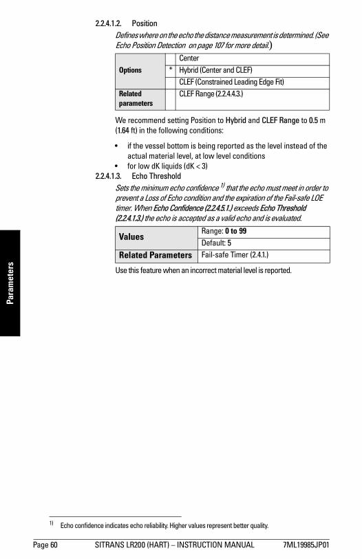
mm
mm
m
Para
met
ers
2.2.4.1.2. Position Defines where on the echo the distance measurement is determined. (See Echo Position Detection on page 107 for more detail.)
We recommend setting Position to Hybrid and CLEF Range to 0.5 m (1.64 ft) in the following conditions:
• if the vessel bottom is being reported as the level instead of the actual material level, at low level conditions
• for low dK liquids (dK < 3)2.2.4.1.3. Echo Threshold
Sets the minimum echo confidence 1) that the echo must meet in order to prevent a Loss of Echo condition and the expiration of the Fail-safe LOE timer. When Echo Confidence (2.2.4.5.1.) exceeds Echo Threshold (2.2.4.1.3.) the echo is accepted as a valid echo and is evaluated.
Use this feature when an incorrect material level is reported.
Options
Center* Hybrid (Center and CLEF)
CLEF (Constrained Leading Edge Fit)Related parameters
CLEF Range (2.2.4.4.3.)
1) Echo confidence indicates echo reliability. Higher values represent better quality.
ValuesRange: 0 to 99Default: 5
Related Parameters Fail-safe Timer (2.4.1.)
Page 60 SITRANS LR200 (HART) – INSTRUCTION MANUAL 7ML19985JP01

mm
mm
m
Parameters
2.2.4.2. SamplingProvides a method of checking the reliability of a new echo before accepting it as the valid reading, based on numbers of samples above or below the currently selected echo.2.2.4.2.1. Echo Lock
Selects the measurement verification process.
For radar applications, Material Agitator is the most often-used setting, to avoid agitator blade detection.
2.2.4.2.4. Sampling up Specifies the number of consecutive echoes that must appear above the echo currently selected, before the measurement is accepted as valid.
2.2.4.2.5. Sampling downSpecifies the number of consecutive echoes that must appear below the echo currently selected, before the measurement is accepted as valid.
Note: Ensure the agitator is always running while SITRANS LR200 is monitoring the vessel, to avoid stationary blade detection.
Options
Lock OffMaximum Verification
* Material AgitatorTotal Lock (not recommended for radar)
Related parame-ters
Fill Rate (2.2.7.2.)Empty rate (2.2.7.3.)Sampling up (2.2.4.2.4.)Sampling down (2.2.4.2.5.)Window (2.2.4.2.6.)
Values Range: 1 to 50Default: 5
Values Range: 1 to 50Default is dependent on the setting for Echo Lock (2.2.4.2.1.)
7ML19985JP01 SITRANS LR200 (HART) – INSTRUCTION MANUAL Page 61

mm
mm
m
Para
met
ers
2.2.4.2.6. WindowA "distance window" centered on the echo1), used to derive the reading. When a new measurement is in the window, the window is re-centered and the reading is calculated.
When the value is 0, the window is automatically calculated after each measurement.
• For slower Measurement Response values, the window is narrow.
• For faster Measurement Response values, the window becomes progressively wider.
2.2.4.3. Filtering2.2.4.3.2. Damping Filter
The time constant for the damping filter. The engineering unit is always in seconds. This is an exponential filter. When a change occurs in the input, the output will be at 63.2% of the change in one time constant, and will be at full change after 5 time constants
2.2.4.4. Tank Bottom Algorithm2.2.4.4.3. CLEF Range
CLEF range is the level below which the Hybrid setting for Position (2.2.4.1.2.) will change to CLEF. If a stillpipe is being used, the setting for CLEF Range will be determined by the horn size. See Propagation Factor (2.2.1.14.) for a table of values.
We recommend setting Position to Hybrid and CLEF Range to 0.5 m (1.64 ft) in the following conditions:
• if the vessel bottom is being reported as the level instead of the actual material level, at low level conditions
• for low dK liquids (dK < 3)
1) See Echo Lock on page 106 for more detail.
Values Range: 0 to 20 mDefault: 0
Note: The echo lock window is stored as standard sample, but displayed sensor units. Any value entered for the echo lock window will be rounded to the nearest sample.
Values Range: 0 to 100.000 sDefault: 10.000 s
Values Range: 0 to 20 m (0 to 65.6 ft)Default: 0.0 m
Related parameters Position (2.2.4.1.2.)
Page 62 SITRANS LR200 (HART) – INSTRUCTION MANUAL 7ML19985JP01

mm
mm
m
Parameters
2.2.4.5. Noise2.2.4.5.1. Echo Confidence
Indicates echo reliability: higher values represent better echo quality. Echo Threshold (2.2.4.1.3.) defines the minimum criterion for echo confidence.
In SIMATIC PDM, open the menu View – Profile.
2.2.4.5.2. Echo StrengthDisplays the absolute strength (in dB above 1 µV rms) of the echo selected as the measurement echo.
In SIMATIC PDM, open the menu View – Profile.
2.2.4.5.3. Noise AverageDisplays the average ambient noise (in dB above 1 µV rms) of a noise profile. Noise level is a combination of transient noise and receiving circuitry. After a measurement, the values from the previous noise shot will be displayed.
2.2.5. TVT (Auto False Echo Suppression) setupFirst SITRANS LR200 learns the echo profile. Then the learned profile, or part of the learned profile, is used to screen out false echoes. See Before Auto False Echo Suppression on page 65 for examples.2.2.5.1. TVT Hover Level
Defines in percent how high the TVT (Time Varying Threshold) curve is placed above the echo profile, with respect to largest echo. When SITRANS LR200 is located in the center of the vessel, lower this parameter to prevent multiple echo detections. (For an illustration, see Before Auto False Echo Suppression on page 65.)
Values (view only)
0 to 99---- Shot not used
Related Parameters
Echo Threshold (2.2.4.1.3.)
Values (view only) –20 to 99
Values (view only) –15 to 90
Values Range: 0 to 100%
Default: 40%
7ML19985JP01 SITRANS LR200 (HART) – INSTRUCTION MANUAL Page 63

mm
mm
m
Para
met
ers
2.2.5.2. Auto False Echo SuppressionEnables a ’learned’ TVT curve to be used in place of the default TVT curve. (See Auto False Echo Suppression on page 107 for an explanation)
a) Before adjusting these parameters, rotate the instrument for best signal (lower false-echo amplitude).
b) Determine Range (the distance within which the learned TVT will replace the default TVT). Measure the actual distance from the antenna reference point to the material surface using a rope or tape measure, and make allowances for the actual location of the LR200.
c) Subtract 0.5 m (20") from this distance, and use the resulting value.
To use Auto False Echo Suppression via SIMATIC PDM:
d) Open the menu Device – Auto False Echo Suppression and set Range. For more detail see Auto False Echo Suppression on page 44.
e) Select Learn. The device will automatically revert to On (Use Learned TVT) after a few seconds.
See also To set Auto False Echo Suppression via the handheld programmer: on page 65
Notes: • We recommend adjusting Auto False Echo Suppression parameters
with an empty or almost empty vessel.• Set Auto False Echo Suppression and Auto False Echo Range during
startup, if possible.• If the vessel contains an agitator, the agitator should be running.
Options
OFF Default TVT curve will be used.
* ON ’Learned’ TVT curve will be used.
LEARN ’Learn’ the TVT curve.
Page 64 SITRANS LR200 (HART) – INSTRUCTION MANUAL 7ML19985JP01

mm
mm
m
Parameters
To set Auto False Echo Suppression via the handheld programmer:
d) Go to Auto Suppression Range (2.2.5.3.) and enter new value.
e) Press RIGHT arrow to open Edit Mode
f) Select Learn. The device will automatically revert to On (Use Learned TVT) after a few seconds.
2.2.5.3. Auto Suppression RangeDefines the endpoint of the Learned TVT distance. Units are defined in sensor units.
a) Press RIGHT arrow to open Edit mode.b) Enter the new value and press RIGHT arrow to accept it.c) Set Auto False Echo Suppression (2.2.5.2.).
2.2.5.4. Shaper ModeAdjusts the TVT curve at a specified range.
Values Range: 0.00 to 20.00 m
Default: 1.00 m
OptionsON
* OFF
Before Auto False Echo Suppression
default TVT
TVTHover Level
echomarker
After Auto False Echo Suppression
learned TVT curve
liquid level
false echo
echo marker
7ML19985JP01 SITRANS LR200 (HART) – INSTRUCTION MANUAL Page 65

mm
mm
m
Para
met
ers
2.2.6. TVT shaper
A breakpoint on the TVT curve. This allows you to reshape the TVT curve to avoid unwanted echoes. There are 40 breakpoints arranged in 5 groups. (We recommend using SIMATIC PDM to access this feature.)
To use TVT shaper via LUI (local user interface):
a) Go to Shaper Mode (2.2.5.4.) and select option ON.b) In TVT shaper, go to Shaper 1-9 (2.2.6.1.).c) Open Shaper 1 and enter the TVT Offset value (between –50 and 50).d) Go to the next Shaper point and repeat step (c) till all desired breakpoint
values have been entered.
2.2.6.1. Shaper 1-9
2.2.6.2. Shaper 10-18
2.2.6.3. Shaper 19-27
2.2.6.4. Shaper 28-36
2.2.6.5. Shaper 37-40
To access TVT shaper via SIMATIC PDM:
• Open the menu Device – TVT shaper. • For more details and an illustration see TVT Shaper on page 45.
Note: The range is –50 to +50 dB.
Values Range:–50 to+50 dB
Default: 0 dB
Values Range: –50 to+50 dB
Default: 0 dB
Values Range: –50 to+50 dB
Default: 0 dB
Values Range: –50 to+50 dB
Default: 0 dB
Values Range: –50 to+50 dB
Default: 0 dB
Page 66 SITRANS LR200 (HART) – INSTRUCTION MANUAL 7ML19985JP01

mm
mm
m
Parameters
2.2.7. Rate
2.2.7.1. Response Rate
Sets the reaction speed of the device to measurement changes in the target range.
Use a setting just faster than the maximum filling or emptying rate (whichever is faster).
2.2.7.2. Fill RateDefines the maximum rate at which the reported sensor value1) is allowed to increase. Allows you to adjust the SITRANS LR200 response to increases in the actual material level. Fill Rate is automatically updated whenever Response Rate is altered.
Enter a value slightly greater than the maximum vessel-filling rate, in Sensor Units per minute.
Note: Changing Response Rate resets Fill Rate, Empty Rate, Filter Time Constant and Echo Lock.
Related parame-
ters
Response Rate
(2.2.7.1.)
Fill Rate (2.2.7.2.)
Empty rate
(2.2.7.3.)
Damping Filter
(2.2.4.3.2.)a)
a) Filter Time Constant
Echo Lock
(2.2.4.2.1.)
Options* slow 0.1 m/min. 0.1 m/min. 10 s
mat. agitator
medium 1 m/min. 1 m/min. 10 smat.
agitator
fast 10 m/min. 10 m/min. 0 smat.
agitator
1) See Operation (2.2.1.5.) on page 52 for an illustration.
ValuesRange: 0.0000 to 99999 m / min.
Default: 0.1 m/min.
Altered by Response Rate (2.2.7.1.)
Related parameters Sensor Units (2.2.1.4.)
Options Meters/MinuteSlow 0.1
Medium 1
Fast 10
7ML19985JP01 SITRANS LR200 (HART) – INSTRUCTION MANUAL Page 67

mm
mm
m
Para
met
ers
2.2.7.3. Empty rateDefines the maximum rate at which the reported sensor value1) is allowed to decrease. Adjusts the SITRANS LR200 response to decreases in the actual material level. Empty Rate is automatically updated whenever Response Rate is altered.
Enter a value slightly greater than the vessel’s maximum emptying rate, in Sensor Units per minute.
2.2.8. Transducer Block (TB) Values (for diagnostic purposes)2.2.8.2. Level Measurement
The value for level. Read Only.In SIMATIC PDM, open the menu View – Display, select the tab Display, and check the Level Measurement field.
2.2.8.3. Space MeasurementThe value for space. Read Only.In SIMATIC PDM, open the menu View – Display, select the tab Display, and check the Space Measurement field.
2.2.8.4. Distance MeasurementThe value for distance. Read Only.In SIMATIC PDM, open the menu View – Display, select the tab Display, and check the Distance Measurement field.
2.2.8.5. Volume MeasurementThe value for volume. Read Only.In SIMATIC PDM, open the menu View – Display, select the tab Display, and check the Volume Measurement field.
1) See Operation (2.2.1.5.) on page 52 for an illustration.
ValuesRange: 0.0000 to 99999 m / min.
Default: 0.1
Altered by Response Rate (2.2.7.1.)
Related Sensor Units (2.2.1.4.)
Options Meters/MinuteSlow 0.1
Medium 1
Fast 10
Page 68 SITRANS LR200 (HART) – INSTRUCTION MANUAL 7ML19985JP01
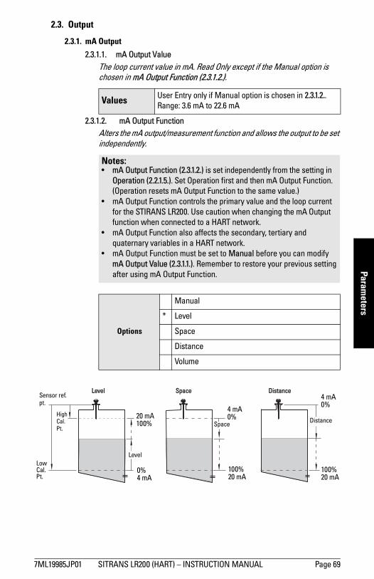
mm
mm
m
Parameters
2.3. Output
2.3.1. mA Output
2.3.1.1. mA Output ValueThe loop current value in mA. Read Only except if the Manual option is chosen in mA Output Function (2.3.1.2.).
2.3.1.2. mA Output FunctionAlters the mA output/measurement function and allows the output to be set independently.
Values User Entry only if Manual option is chosen in 2.3.1.2.. Range: 3.6 mA to 22.6 mA
Notes:• mA Output Function (2.3.1.2.) is set independently from the setting in
Operation (2.2.1.5.). Set Operation first and then mA Output Function. (Operation resets mA Output Function to the same value.)
• mA Output Function controls the primary value and the loop current for the STIRANS LR200. Use caution when changing the mA Output function when connected to a HART network.
• mA Output Function also affects the secondary, tertiary and quaternary variables in a HART network.
• mA Output Function must be set to Manual before you can modify mA Output Value (2.3.1.1.). Remember to restore your previous setting after using mA Output Function.
Options
Manual
* Level
Space
Distance
Volume
Level Space Distance
DistanceSpace
Level
20 mA100%
0%4 mA
HighCal.Pt.
4 mA0%
100% 20 mA
4 mA0%
100% 20 mA
Sensor ref.pt.
Low Cal. Pt.
7ML19985JP01 SITRANS LR200 (HART) – INSTRUCTION MANUAL Page 69
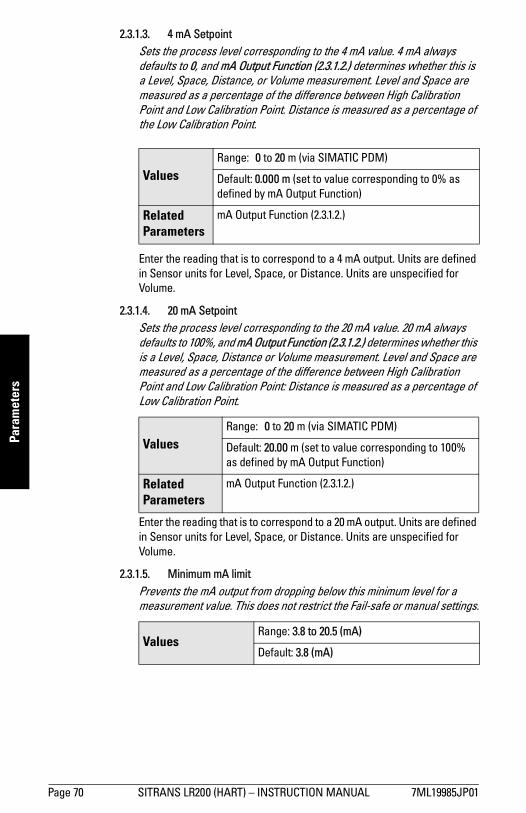
mm
mm
m
Para
met
ers
2.3.1.3. 4 mA SetpointSets the process level corresponding to the 4 mA value. 4 mA always defaults to 0, and mA Output Function (2.3.1.2.) determines whether this is a Level, Space, Distance, or Volume measurement. Level and Space are measured as a percentage of the difference between High Calibration Point and Low Calibration Point. Distance is measured as a percentage of the Low Calibration Point.
Enter the reading that is to correspond to a 4 mA output. Units are defined in Sensor units for Level, Space, or Distance. Units are unspecified for Volume.
2.3.1.4. 20 mA SetpointSets the process level corresponding to the 20 mA value. 20 mA always defaults to 100%, and mA Output Function (2.3.1.2.) determines whether this is a Level, Space, Distance or Volume measurement. Level and Space are measured as a percentage of the difference between High Calibration Point and Low Calibration Point: Distance is measured as a percentage of Low Calibration Point.
Enter the reading that is to correspond to a 20 mA output. Units are defined in Sensor units for Level, Space, or Distance. Units are unspecified for Volume.
2.3.1.5. Minimum mA limitPrevents the mA output from dropping below this minimum level for a measurement value. This does not restrict the Fail-safe or manual settings.
ValuesRange: 0 to 20 m (via SIMATIC PDM)
Default: 0.000 m (set to value corresponding to 0% as defined by mA Output Function)
Related Parameters
mA Output Function (2.3.1.2.)
ValuesRange: 0 to 20 m (via SIMATIC PDM)
Default: 20.00 m (set to value corresponding to 100% as defined by mA Output Function)
Related Parameters
mA Output Function (2.3.1.2.)
ValuesRange: 3.8 to 20.5 (mA)
Default: 3.8 (mA)
Page 70 SITRANS LR200 (HART) – INSTRUCTION MANUAL 7ML19985JP01

mm
mm
m
Parameters
2.3.1.6. Maximum mA limitPrevents the mA output from rising above this maximum level for a measurement value. This does not restrict the Fail-safe or manual settings.
2.3.1.7. 4 mA Output TrimCalibrates the 4 mA output. The mA output of the device is pre-calibrated; however, 4 mA Output Trim can be used to trim remote displays or inputs.
a) Set mA Output Function (2.3.1.2.) to Manual.b) Set mA Output Value (2.3.1.1.) to 4 mA. c) Attach a calibrated meter and check the output at the terminals;
record the remote reading in mA.d) Enter this value in 4 mA Output Trim.e) Restore mA Output Function (2.3.1.2.) to previous setting.f) Confirm that the mA output is as expected.
2.3.1.8. 20 mA Output TrimCalibrates the 20 mA output. The mA output of the device is pre-calibrated; however, 20 mA Output Trim can be used to trim remote displays or inputs.
a) Set mA Output Function (2.3.1.2.) to Manual.b) Set mA Output Value (2.3.1.1.) to 20 mA. c) Attach a calibrated meter and check the output at the terminals;
record the remote reading in mA.d) Enter this value in 20 mA Output Trim.e) Restore mA Output Function (2.3.1.2.) to previous setting.f) Confirm that the mA output is as expected.
ValuesRange: 3.8 to 20.5 (mA)
Default: 20.5 (mA)
Values Range: 2.0 to 6.0 (mA)
Related parameters 20 mA Output Trim (2.3.1.8.)
Values Range: 18.0 to 24.0 (mA)
Related parameters 4 mA Output Trim (2.3.1.7.)
7ML19985JP01 SITRANS LR200 (HART) – INSTRUCTION MANUAL Page 71
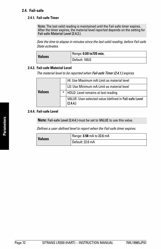
mm
mm
m
Para
met
ers
2.4. Fail-safe
2.4.1. Fail-safe Timer
Sets the time to elapse in minutes since the last valid reading, before Fail-safe State activates.
2.4.2. Fail-safe Material LevelThe material level to be reported when Fail-safe Timer (2.4.1.) expires.
2.4.4. Fail-safe Level
Defines a user-defined level to report when the Fail-safe timer expires.
Note: The last valid reading is maintained until the Fail-safe timer expires. After the timer expires, the material level reported depends on the setting for Fail-safe Material Level (2.4.2.).
Values Range: 0.00 to720 min.
Default: 100.0
Values
HI: Use Maximum mA Limit as material level
LO: Use Minimum mA Limit as material level
* HOLD: Level remains at last reading
VALUE: User-selected value (defined in Fail-safe Level (2.4.4.)
Note: Fail-safe Level (2.4.4.) must be set to VALUE to use this value.
Values Range: 3.58 mA to 22.6 mA
Default: 22.6 mA
Page 72 SITRANS LR200 (HART) – INSTRUCTION MANUAL 7ML19985JP01

mm
mm
m
Parameters
3. Diagnostics
Use these parameters to set up schedules for calibration and maintenance. The device will track itself based on operating hours instead of a calendar-based schedule, and will monitor its predicted lifetime.
The maintenance warnings and alarms are available through HART Communications. This information can be integrated into an Asset Management system. We recommend that you use SIMATIC PCS7 Asset Management Software in conjunction with SIMATIC PDM.
Open the menu View – Device Status and click on the appropriate tab to monitor maintenance and diagnostics conditions.
7ML19985JP01 SITRANS LR200 (HART) – INSTRUCTION MANUAL Page 73
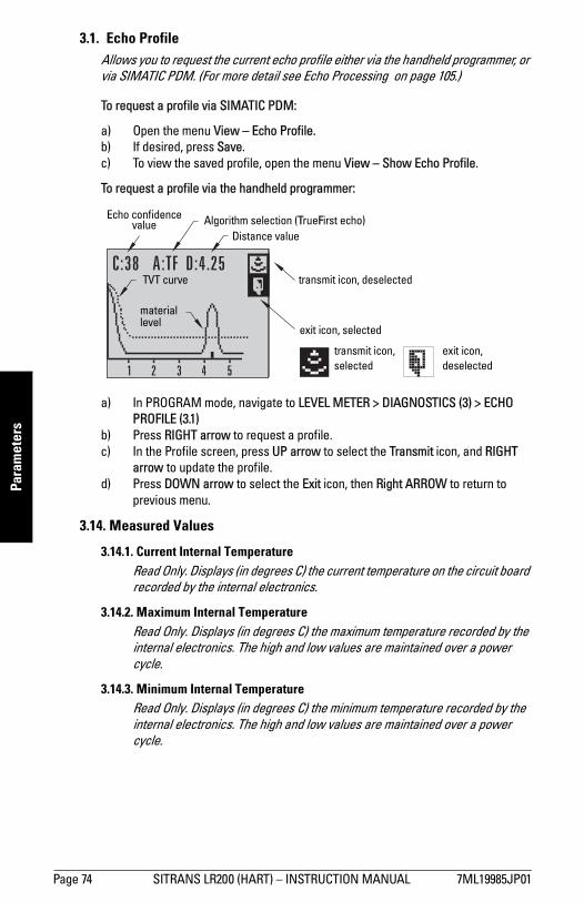
mm
mm
m
Para
met
ers
3.1. Echo ProfileAllows you to request the current echo profile either via the handheld programmer, or via SIMATIC PDM. (For more detail see Echo Processing on page 105.)
To request a profile via SIMATIC PDM:
a) Open the menu View – Echo Profile. b) If desired, press Save. c) To view the saved profile, open the menu View – Show Echo Profile.
To request a profile via the handheld programmer:
a) In PROGRAM mode, navigate to LEVEL METER > DIAGNOSTICS (3) > ECHO PROFILE (3.1)
b) Press RIGHT arrow to request a profile.c) In the Profile screen, press UP arrow to select the Transmit icon, and RIGHT
arrow to update the profile. d) Press DOWN arrow to select the Exit icon, then Right ARROW to return to
previous menu.
3.14. Measured Values
3.14.1. Current Internal TemperatureRead Only. Displays (in degrees C) the current temperature on the circuit board recorded by the internal electronics.
3.14.2. Maximum Internal TemperatureRead Only. Displays (in degrees C) the maximum temperature recorded by the internal electronics. The high and low values are maintained over a power cycle.
3.14.3. Minimum Internal TemperatureRead Only. Displays (in degrees C) the minimum temperature recorded by the internal electronics. The high and low values are maintained over a power cycle.
C:38 A:TF D:4.25
1 2 3 4 5
transmit icon, selected
exit icon, deselected
exit icon, selected
transmit icon, deselected
Distance valueAlgorithm selection (TrueFirst echo)
TVT curve
material level
Echo confidence value
Page 74 SITRANS LR200 (HART) – INSTRUCTION MANUAL 7ML19985JP01

mm
mm
m
Parameters
3.15. Remaining Device Lifetime
The device tracks itself based on operating hours instead of a calendar-based schedule, and monitors its predicted lifetime. You can modify the expected device lifetime, set up schedules for maintenance alerts, and acknowledge them.
The maintenance warnings and alarms are available through HART Communications. This information can be integrated into an Asset Management system. For optimal use, we recommend that you use SIMATIC PCS7 Asset Management Software in conjunction with SIMATIC PDM.
To access these parameters via SIMATIC PDM:• Open the menu Device – Maintenance and select the Remaining Device Lifetime
tab.• After modifying values/units as required, click on Write to accept the change,
and Read to view the effect of the change.• Click on Snooze to add a year to the Total Expected Device Life.
Notes: • Four sets of parameters allow you to monitor the Device/Sensor Lifetimes and
set up Maintenance/Service schedules, based on operating hours instead of a calendar-based schedule. See also Remaining Sensor Lifetime (3.16.), Service Interval (4.16.), and Calibration Interval (4.17.).
• Performing a reset to Factory Defaults will reset all the Maintenance Schedule parameters to their factory defaults.
• The device operates in years. To view Remaining Device Lifetime parameters in hours or days (via SIMATIC PDM only) see Total Expected Device Life (3.15.6.).
7ML19985JP01 SITRANS LR200 (HART) – INSTRUCTION MANUAL Page 75

mm
mm
m
Para
met
ers
3.15.1. Total Device Operating TimeRead only. The amount of time the device has been operating.
3.15.2. Remaining Device LifetimeRead only. Total Expected Device Life (3.15.6.) less Total Device Operating Time (3.15.1.).
3.15.3. Maintenance Required LimitIf Remaining Device Lifetime (3.15.2.) is equal to or less than this limit, the device sets Maintenance Required.
a) Modify limit values as required.b) Set Maintenance Alert Activation (3.15.5.) to the desired option.
3.15.4. Maintenance Demanded LimitIf Remaining Device Lifetime (3.15.2.)is equal to or less than this limit, the device sets Maintenance Demanded.
a) Modify limit values as required. b) Set Maintenance Alert Activation (3.15.5.) to the desired option.
3.15.5. Maintenance Alert Activation
Allows you to enable a maintenance limit.
a) First set the limit values in Maintenance Required Limit (3.15.3.)/Maintenance Demanded Limit (3.15.4.).
b) Select the desired Maintenance Alert Activation option.
ValuesRange: 0 to 20 years
Default: 0.164 years
ValuesRange: 0 to 20 years
Default: 0.019 years
Note: To modify this parameter via SIMATIC PDM it must be accessed via the pull-down menu Device – Maintenance.
Options
Warning Limit 1 (Maintenance Required Limit)
Warning Limit 2 (Maintenance Demanded Limit)
Warning Limits 1 and 2 (Maintenance Required and Maintenance Demanded Limits)
* OFF
Page 76 SITRANS LR200 (HART) – INSTRUCTION MANUAL 7ML19985JP01

mm
mm
m
Parameters
3.15.6. Total Expected Device Life
Allows you to override the factory default.
3.15.7. Maintenance StatusDisplays the status of the Maintenance limits.In SIMATIC PDM open the menu View – Device Status, click on the Maintenance tab, and check the Device Lifetime Status window.
3.15.8. Acknowledge StatusAcknowledges the status of the Maintenance limits.In SIMATIC PDM open the menu View – Device Status, click on the Maintenance tab, and check the Device Lifetime Status window.
3.15.9. Acknowledge Acknowledges the current limit status.
To acknowledge an alert via SIMATIC PDM:
a) Open the menu View – Device Status and click on the Maintenance tab.b) In the Device Lifetime section click on Acknowledge Warnings.
To acknowledge an alert via the handheld programmer: a) Press RIGHT arrow twice to open parameter view and activate Edit
Mode.
b) Press RIGHT arrow to acknowledge the alert.
Note: The device always operates in years. Changing the units affects only the parameter view of the Remaining Device Lifetime parameters in SIMATIC PDM.
ValuesUnitsa): hours, days, years
a) Units are selectable only via SIMATIC PDM.
Range: 0 to 20 years (or equivalent)
Default: 10.00 years
7ML19985JP01 SITRANS LR200 (HART) – INSTRUCTION MANUAL Page 77

mm
mm
m
Para
met
ers
3.16. Remaining Sensor Lifetime
The device monitors the predicted lifetime of the sensor (the components exposed to the vessel environment). You can modify the expected sensor lifetime, set up schedules for maintenance alerts, and acknowledge them.
To access these parameters via SIMATIC PDM:• Open the menu Device – Maintenance and select the Remaining Sensor
Lifetime tab.• After modifying values as required, click on Write to accept the change, and
Read to view the effect of the change.• Click on Snooze to add a year to the Total Expected Sensor Life.• Click on Sensor Replaced to restart the timer and clear any fault messages.
Notes: • Four sets of parameters allow you to monitor the Device/Sensor Lifetimes and
set up Maintenance/Service schedules, based on operating hours instead of a calendar-based schedule. See also Remaining Device Lifetime (3.15.), Service Interval (4.16.), and Calibration Interval (4.17.).
• Performing a reset to Factory Defaults will reset all the Maintenance Schedule parameters to their factory defaults.
• The device operates in years. To view Remaining Sensor Lifetime parameters in hours or days (via SIMATIC PDM only) see Total Expected Sensor Life (3.16.6.).
Page 78 SITRANS LR200 (HART) – INSTRUCTION MANUAL 7ML19985JP01
mm
mm
m
Parameters
3.16.1. Total Sensor Operating TimeThe amount of time the sensor has been operating. Can be reset to zero via the handheld programmer after performing a service or replacing the sensor.To reset to zero:• In SIMATIC PDM, open the menu Device – Maintenance, click on the
Remaining Sensor Lifetime tab, and click on Sensor Replaced to restart the timer and clear any fault messages.
• Via the handheld programmer, manually reset Total Sensor Operating Time (3.16.1.) to zero.
3.16.2. Remaining Sensor LifetimeRead only. Total Expected Sensor Life (3.16.6.) less Total Sensor Operating Time (3.16.1.).
3.16.3. Maintenance Required LimitIf Remaining Sensor Lifetime (3.16.2.) is equal to or less than this limit, the device sets Maintenance Required.
a) Modify limit values as required.b) Set Maintenance Alert Activation (3.16.5.) to the desired option.
3.16.4. Maintenance Demanded LimitIf Remaining Sensor Lifetime (3.16.2.) is equal to or less than this limit, the device sets Maintenance Demanded.
a) Modify limit values as requiredb) Set Maintenance Alert Activation (3.16.5.) to the desired option.
ValuesRange: 0 to 20 years
Default: 0.164 years
ValuesRange: 0 to 20 years
Default: 0.019 years
7ML19985JP01 SITRANS LR200 (HART) – INSTRUCTION MANUAL Page 79
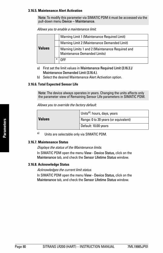
mm
mm
m
Para
met
ers
3.16.5. Maintenance Alert Activation
Allows you to enable a maintenance limit.
a) First set the limit values in Maintenance Required Limit (3.16.3.)/Maintenance Demanded Limit (3.16.4.).
b) Select the desired Maintenance Alert Activation option.
3.16.6. Total Expected Sensor Life
Allows you to override the factory default.
3.16.7. Maintenance StatusDisplays the status of the Maintenance limits.In SIMATIC PDM open the menu View - Device Status, click on the Maintenance tab, and check the Sensor Lifetime Status window.
3.16.8. Acknowledge StatusAcknowledges the current limit status.In SIMATIC PDM open the menu View - Device Status, click on the Maintenance tab, and check the Sensor Lifetime Status window.
Note: To modify this parameter via SIMATIC PDM it must be accessed via the pull-down menu Device – Maintenance.
Values
Warning Limit 1 (Maintenance Required Limit)
Warning Limit 2 (Maintenance Demanded Limit)
Warning Limits 1 and 2 (Maintenance Required and Maintenance Demanded Limits)
* OFF
Note: The device always operates in years. Changing the units affects only the parameter view of Remaining Sensor Life parameters in SIMATIC PDM.
ValuesUnitsa): hours, days, years
a) Units are selectable only via SIMATIC PDM.
Range: 0 to 20 years (or equivalent)
Default: 10.00 years
Page 80 SITRANS LR200 (HART) – INSTRUCTION MANUAL 7ML19985JP01

mm
mm
m
Parameters
3.16.9. Acknowledge Acknowledges the current limit status.
To acknowledge an alert via SIMATIC PDM:
a) Open the menu View – Device Status and click on the Maintenance tab.b) In the Sensor Lifetime section click on Acknowledge Warnings.
To acknowledge an alert via the handheld programmer:
a) Press RIGHT arrow twice to open parameter view and activate Edit
Mode.
b) Press RIGHT arrow to acknowledge the alert.
4. Service 4.1. Device Reset
Resets all parameter to factory defaults, with the following exceptions:
• The Lock and Unlock values are not reset. • The learned TVT curve is not lost.
To perform a reset to factory defaults via SIMATIC PDM, open the menu Device – Device Reset and click on Factory Defaults.
4.2. Manufacture DateThe date of manufacture of the SITRANS LR200 (yy mm dd).
4.3. LCD Fast Mode
Enables a faster rate of measurement from the device by disabling most of the display area. Only the bar graph will be refreshed when LCD Fast Mode is set to ON.
Note: Following a reset to factory defaults, complete reprogramming is required.
Options* Idle or Done (Return to previous menu)
Factory Defaults
Note: Affects Measurement mode only: has no effect on Navigation mode.
Values ON or OFF. Default: OFF
7ML19985JP01 SITRANS LR200 (HART) – INSTRUCTION MANUAL Page 81

mm
mm
m
Para
met
ers
4.4. LCD Contrast The factory setting is for optimum visibility at room temperature and in average light conditions. Extremes of temperature will lessen the contrast.
Adjust the value to improve visibility in different temperatures and luminosity. Change the value in small steps to ensure you can continue to read the display.
4.6. Powered HoursDisplays the number of hours the unit has been powered up since manufacture (displayed in days, in SIMATIC PDM).
Open the menu View – Wear.
4.8. Power-on ResetsThe number of power cycles that have occurred since manufacture.
Open the menu View – Wear.
4.11. Memory Test
Allows verification of the RAM, EEPROM, and Flash memory of the SITRANS LR200.
Press any numeric key from 1 to 9 to activate the test. The reading will display BUSY followed by the test result text.
Values Range: 0 (High contrast) to 20 (Low contrast). Default: 8
LCD Display
IDLE No test in progress.
BUSY Test in progress.
PASS Memory test successful.
FAIL Test failed.
Err1 Test returned unexpected results.
P Oxcafe Test passed with result data.
F Oxcafe Test failed with result data.
Handheld programmer entry to
Any numeric key from 1 to 9 activates test.
Page 82 SITRANS LR200 (HART) – INSTRUCTION MANUAL 7ML19985JP01

mm
mm
m
Parameters
4.16. Service Interval
The device tracks service intervals based on operating hours and monitors the predicted lifetime to the next service. You can modify the Total Service Interval, set schedules for Maintenance Alerts, and acknowledge them.
The maintenance warnings and alarms are available through HART Communication. This information can be integrated into an Asset Management system. For optimal use, we recommend that you use SIMATIC PCS7 Asset Management Software in conjunction with SIMATIC PDM.
To access these parameters via SIMATIC PDM:• Open the menu Device – Maintenance and select the Service Interval tab.• After modifying values/units as required, click on Write to accept the change,
and Read to view the effect of the change. • Click on Service Performed to restart the timer and clear any fault messages.
Notes: • Four sets of parameters allow you to monitor the Device/Sensor Lifetimes and
set up Maintenance/Service schedules, based on operating hours instead of a calendar-based schedule. See also Remaining Device Lifetime (3.15.), Remaining Sensor Lifetime (3.16.), and Calibration Interval (4.17.).
• Performing a reset to Factory Defaults will reset all the Maintenance Schedule parameters to their factory defaults.
• The device operates in years. To view Service Interval parameters in hours or days (via SIMATIC PDM only) see Total Service Interval (4.16.6.).
7ML19985JP01 SITRANS LR200 (HART) – INSTRUCTION MANUAL Page 83
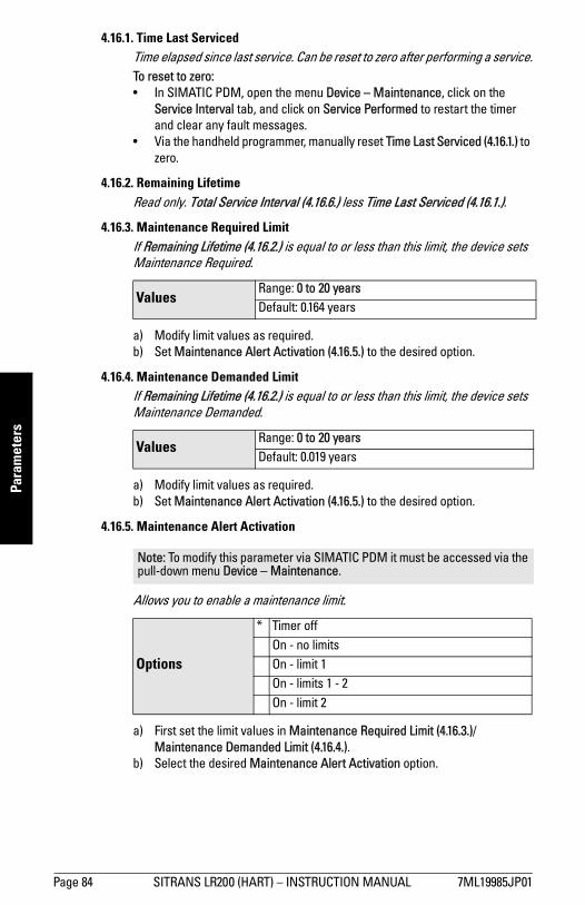
mm
mm
m
Para
met
ers
4.16.1. Time Last ServicedTime elapsed since last service. Can be reset to zero after performing a service.To reset to zero:• In SIMATIC PDM, open the menu Device – Maintenance, click on the
Service Interval tab, and click on Service Performed to restart the timer and clear any fault messages.
• Via the handheld programmer, manually reset Time Last Serviced (4.16.1.) to zero.
4.16.2. Remaining LifetimeRead only. Total Service Interval (4.16.6.) less Time Last Serviced (4.16.1.).
4.16.3. Maintenance Required LimitIf Remaining Lifetime (4.16.2.) is equal to or less than this limit, the device sets Maintenance Required.
a) Modify limit values as required.b) Set Maintenance Alert Activation (4.16.5.) to the desired option.
4.16.4. Maintenance Demanded LimitIf Remaining Lifetime (4.16.2.) is equal to or less than this limit, the device sets Maintenance Demanded.
a) Modify limit values as required.b) Set Maintenance Alert Activation (4.16.5.) to the desired option.
4.16.5. Maintenance Alert Activation
Allows you to enable a maintenance limit.
a) First set the limit values in Maintenance Required Limit (4.16.3.)/Maintenance Demanded Limit (4.16.4.).
b) Select the desired Maintenance Alert Activation option.
ValuesRange: 0 to 20 yearsDefault: 0.164 years
ValuesRange: 0 to 20 yearsDefault: 0.019 years
Note: To modify this parameter via SIMATIC PDM it must be accessed via the pull-down menu Device – Maintenance.
Options
* Timer offOn - no limitsOn - limit 1 On - limits 1 - 2On - limit 2
Page 84 SITRANS LR200 (HART) – INSTRUCTION MANUAL 7ML19985JP01

mm
mm
m
Parameters
4.16.6. Total Service Interval
User-configurable recommended time between product inspections
4.16.7. Maintenance StatusDisplays the status of the Maintenance limits.Open the menu View – Device Status, click on the Maintenance tab and check the Service Schedule Status window.
4.16.8. Acknowledge StatusAcknowledges the status of the Maintenance limits.Open the menu View – Device Status, click on the Maintenance tab and check the Service Schedule Status window.
4.16.9. AcknowledgeAcknowledges the current limit status.
To acknowledge an alert via SIMATIC PDM:
a) Open the menu View – Device Status and click on the Maintenance tab.b) In the Service Schedule Status section click on Acknowledge Warnings.
To acknowledge an alert via the handheld programmer:
a) Press RIGHT arrow twice to open parameter view and activate Edit
Mode.
b) Press RIGHT arrow to acknowledge the alert.
Note: The device always operates in years. Changing the units affects only the parameter view of the Service Interval parameters in SIMATIC PDM.
ValuesUnitsa): hours, days, years
a) Units are selectable only via SIMATIC PDM.
Range: 0 to 20 years
Default: 1.0 year
7ML19985JP01 SITRANS LR200 (HART) – INSTRUCTION MANUAL Page 85

mm
mm
m
Para
met
ers
4.17. Calibration Interval
The device tracks calibration intervals based on operating hours and monitors the predicted lifetime to the next calibration. You can modify the Total Calibration Interval, set schedules for Maintenance Alerts, and acknowledge them.
To access these parameters via SIMATIC PDM:• Open the menu Device – Maintenance and select the Calibration Interval tab.• After modifying values/units as required, click on Write to accept the change,
and Read to view the effect of the change.• Click on Calibration Performed to restart the timer and clear any fault
messages.
Notes: • Four sets of parameters allow you to monitor the Device/Sensor Lifetimes and
set up Maintenance/Service schedules, based on operating hours instead of a calendar-based schedule. See also Remaining Device Lifetime (3.15.), Remaining Sensor Lifetime (3.16.), and Service Interval (4.16.).
• Performing a reset to Factory Defaults will reset all the Maintenance Schedule parameters to their factory defaults.
• The device operates in years. To view Calibration Interval parameters in hours or days (via SIMATIC PDM only) see Total Calibration Interval (4.17.6.).
Page 86 SITRANS LR200 (HART) – INSTRUCTION MANUAL 7ML19985JP01

mm
mm
m
Parameters
4.17.1. Time Last CalibratedTime elapsed since last calibration. Can be reset to zero after performing a calibration.
To reset to zero:
• In SIMATIC PDM, open the menu Device – Maintenance, click on the Calibration Interval tab, and click on Calibration Performed to restart the timer and clear any fault messages.
• Via the handheld programmer, manually reset Time Last Calibrated (4.17.1.) to zero.
4.17.2. Remaining LifetimeRead only. Total Calibration Interval (4.17.6.) less Time Last Calibrated (4.17.1.).
4.17.3. Maintenance Required LimitIf Remaining Lifetime (4.17.2.) is equal to or less than this limit, the device sets Maintenance Required.
a) Modify limit values as required.
b) Set Maintenance Alert Activation (4.17.5.) to the desired option.
4.17.4. Maintenance Demanded LimitIf Remaining Lifetime (4.17.2.) is equal to or less than this limit, the device sets Maintenance Demanded.
a) Modify limit values as required.
b) Set Maintenance Alert Activation (4.17.5.) to the desired option.
ValuesRange: 0 to 20 years
Default: 0.164 years
ValuesRange: 0 to 20 years
Default: 0.019 years
7ML19985JP01 SITRANS LR200 (HART) – INSTRUCTION MANUAL Page 87

mm
mm
m
Para
met
ers
4.17.5. Maintenance Alert Activation
Allows you to enable a maintenance limit.
a) First set the limit values in Maintenance Required Limit (4.17.3.)/Maintenance Demanded Limit (4.17.4.).
b) Select the desired Maintenance Alert Activation option.
4.17.6. Total Calibration Interval
User-configurable recommended time between product calibrations.
4.17.7. Maintenance StatusDisplays the status of the Maintenance limits.In SIMATIC PDM, open the menu View – Device Status, click on the Maintenance tab and check the Calibration Schedule Status window.
4.17.8. Acknowledge StatusAcknowledges the status of the Maintenance limits.In SIMATIC PDM, open the menu View – Device Status, click on the Maintenance tab and check the Calibration Schedule Status window.
Note: To modify this parameter via SIMATIC PDM it must be accessed via the pull-down menu Device – Maintenance.
Options
* Timer off
On - no limits
On - limit 1
On - limits 1 - 2
On - limit 2
Note: The device always operates in years. Changing the units affects only the parameter view of the Calibration Interval parameters in SIMATIC PDM.
ValuesUnitsa): hours, days, years
a) Units are selectable only via SIMATIC PDM.
Range: 0 to 20 years
Default: 1.0 year
Page 88 SITRANS LR200 (HART) – INSTRUCTION MANUAL 7ML19985JP01

mm
mm
m
Parameters
4.17.9. AcknowledgeAcknowledges the current limit status.
To acknowledge an alert via SIMATIC PDM:
a) Open the menu View – Device Status and click on the Maintenance tab.b) In the Calibration Schedule Status section click on Acknowledge
Warnings.
To acknowledge an alert via the handheld programmer:
a) Press RIGHT arrow twice to open parameter view and activate Edit
Mode.
b) Press RIGHT arrow to acknowledge the alert.
5. Communication5.1. Device Address
Sets the device address or poll ID on a HART network. Any address other than 0 will cause the output current to be a fixed value, and the current will not indicate the reading.
To change Device Address via SIMATIC PDM:
a) Open the menu Device – Set Address.b) Enter value in New Address field and click on Assign Address.
To change Device Address via the handheld programmer:
• See Device Address on page 32.
5.2. Communication Control
Enables /disables the read/write access to parameters via remote communications.
ValuesRange: 0 to 15Default: 0
Note: SITRANS LR200 can only reset this parameter via the handheld programmer.
Options
Read Only No changes are permitted via remote communications.
* Read Write Changes are permitted.
Restricted Sets the status to Read Only, with the potential for another HART device to change this via remote communications.
7ML19985JP01 SITRANS LR200 (HART) – INSTRUCTION MANUAL Page 89

mm
mm
m
Para
met
ers
6. Security6.1. Lock
Prevents any changes to parameters via the handheld programmer.
Note: This lock applies only to the handheld programmer. A remote master can change configuration if 5.2 Communication Control is set to allow this.
To secure the programming lock: key in any value other than the unlock value. Parameters are now locked and cannot be changed.
To unlock the device and enable handheld programming changes: key in the unlock value. Parameters are now unlocked and may be changed.
6.2. Unlock value
Stores the value to be entered in Lock (6.1.) to unlock programming. If Lock is on, Unlock Value will not display the unlocked value
Note: Do not lose the unlock value.
Handheld programmer Values
1954 (factory default unlock value)
Off (enables local programming)
any other value On (disables local programming)
Notes: • Default setting for Lock (6.1.) is Unlocked. • After a new value is stored in Unlock value (6.2.), that value will be recalled after
a Factory Reset.• Consult your Siemens Milltronics representative if you have forgotten the
unlock value.
Handheld programmer Values
Range 1 to 9999
Default 1954
---- Display when Lock is on
Page 90 SITRANS LR200 (HART) – INSTRUCTION MANUAL 7ML19985JP01

mm
mm
m
Parameters
7. LanguageSelects the language to be displayed on the LCD.
Options
* English
German
French
Spanish
7ML19985JP01 SITRANS LR200 (HART) – INSTRUCTION MANUAL Page 91

mm
mm
m
Para
met
ers
Notes
Page 92 SITRANS LR200 (HART) – INSTRUCTION MANUAL 7ML19985JP01

mm
mm
m
A: Param
eter List
Appendix A: Alphabetical Parameter List
Note: Maintenance Parameters are not listed below. See Remaining Device Lifetime (3.15.) on page 75 , Remaining Sensor Lifetime (3.16.) on page 78 , Service Interval (4.16.) on page 83 , and Calibration Interval (4.17.) on page 86 for those parameters.
Parameter Name (Parameter Number) Page Number
20 mA Output Trim (2.3.1.8.) 7120 mA Setpoint (2.3.1.4.) 704 mA Output Trim (2.3.1.7.) 714 mA Setpoint (2.3.1.3.) 70Algorithm (2.2.4.1.1.) 59Auto False Echo Suppression (2.2.5.2.) 64Auto Suppression Range (2.2.5.3.) 65CLEF Range (2.2.4.4.3.) 62Communication Control (5.2.) 89Current Internal Temperature (3.14.1.) 74Damping Filter (2.2.4.3.2.) 62Device Address (5.1.) 89Device Reset (4.1.) 81Dimension A (2.2.3.2.) 57Dimension L (2.2.3.3.) 57Distance Measurement (2.2.8.4.) 68Echo Confidence (2.2.4.5.1.) 63Echo Lock (2.2.4.2.1.) 61Echo Profile (3.1.) 74Echo Strength (2.2.4.5.2.) 63Echo Threshold (2.2.4.1.3.) 60Empty rate (2.2.7.3.) 68Fail-safe Level (2.4.4.) 72Fail-safe Material Level (2.4.2.) 72Fail-safe Timer (2.4.1.) 72Far Range (2.2.1.12.) 53Fill Rate (2.2.7.2.) 67Firmware Revision (2.1.1.) 51Hardware Revision (2.1.3.) 51High Calibration Point (1.6.) 51Language (7.) 91Level Measurement (2.2.8.2.) 68
7ML19985JP01 SITRANS LR200 (HART) – INSTRUCTION MANUAL Page 93
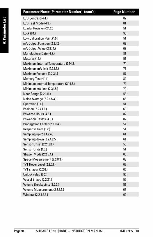
mm
mm
m
A: P
aram
eter
Lis
t
LCD Contrast (4.4.) 82LCD Fast Mode (4.3.) 81Loader Revision (2.1.2.) 51Lock (6.1.) 90Low Calibration Point (1.5.) 51mA Output Function (2.3.1.2.) 69mA Output Value (2.3.1.1.) 69Manufacture Date (4.2.) 81Material (1.1.) 51Maximum Internal Temperature (3.14.2.) 74Maximum mA limit (2.3.1.6.) 71Maximum Volume (2.2.3.1.) 57Memory Test (4.11.) 82Minimum Internal Temperature (3.14.3.) 74Minimum mA limit (2.3.1.5.) 70Near Range (2.2.1.11.) 53Noise Average (2.2.4.5.3.) 63Operation (1.4.) 51Position (2.2.4.1.2.) 60Powered Hours (4.6.) 82Power-on Resets (4.8.) 82Propagation Factor (2.2.1.14.) 54Response Rate (1.2.) 51Sampling up (2.2.4.2.4.) 61Sampling down (2.2.4.2.5.) 61Sensor Offset (2.2.1.20.) 55Sensor Units (1.3.) 51Shaper Mode (2.2.5.4.) 65Space Measurement (2.2.8.3.) 68TVT Hover Level (2.2.5.1.) 63TVT shaper (2.2.6.) 66Unlock value (6.2.) 90Vessel Shape (2.2.2.1.) 55Volume Breakpoints (2.2.3.) 57Volume Measurement (2.2.8.5.) 68Window (2.2.4.2.6.) 62Parameter Name (Parameter Number) (cont’d) Page Number
Page 94 SITRANS LR200 (HART) – INSTRUCTION MANUAL 7ML19985JP01

mm
mm
m
B: Troubleshooting
Appendix B: Troubleshooting
Communication Troubleshooting1. Check the following:
• There is power at the instrument• The LCD shows the relevant data• The device can be programmed using the hand programmer
2. Verify that the wiring connections are correct.
3. See the table below for specific symptoms.
If you continue to experience problems, go to our website at:
www.siemens.com/processautomation, and check the FAQs for SITRANS LR200, or contact your local Siemens Milltronics representative.
Symptom Corrective action
The device cannot be pro-grammed via the handheld pro-grammer.
• Ensure Lock (6.1.) is set to the unlock value.
You try to set a parameter via remote communications but it remains unchanged.
• Make sure Lock (6.1.) on page 90 is set to the unlock value, then try setting the parameter via the handheld programmer.
• Make sure Communication Control (5.2.) on page 89 is set to READ WRITE to enable changes.
• Some parameters can only be changed when the device is not scanning. Try pressing Mode to put the device into PROGRAM mode.
You see unanticipated dis-plays, for example:• PROGRAM mode
displayed instead of Measurement mode
• the wrong parameter displayed in response to a command
• a parameter displayed in response to no command
• Make sure no infrared-capable device is close to SITRANS LR200. Any device with infrared capabilities (laptops, cell phones, PDAs) can cause interference which simulates a command to the SITRANS LR200, potentially causing it to switch modes or to change a parameter.
Operation is erratic. • Make sure the handheld programmer is not being
used at the same time as SIMATIC PDM.
7ML19985JP01 SITRANS LR200 (HART) – INSTRUCTION MANUAL Page 95

mm
mm
m
B: T
roub
lesh
ootin
g
Device Status Icons
Icon PriorityLevel Meaning
1 • Maintenance alarm • Measurement values are not valid
2 • Maintenance warning: maintenance demanded immediately• Measured signal still valid
3 • Maintenance required• Measured signal still valid
1 • Process value has reached an alarm limit
2 • Process value has reached a warning limit
3 • Process value has reached a tolerance limit
1 • Configuration error• Device will not work because one or more parameters/
components is incorrectly configured
2 • Configuration warning• Device can work but one or more parameters/components is
incorrectly configured
3 • Configuration changed• Device parameterization not consistent with parameterization in
project. Look for info text.
1 • Manual operation (local override)• Communication is good; device is in manual mode.
2 • Simulation or substitute value• Communication is good; device is in simulation mode or works
with substitute values.
Page 96 SITRANS LR200 (HART) – INSTRUCTION MANUAL 7ML19985JP01
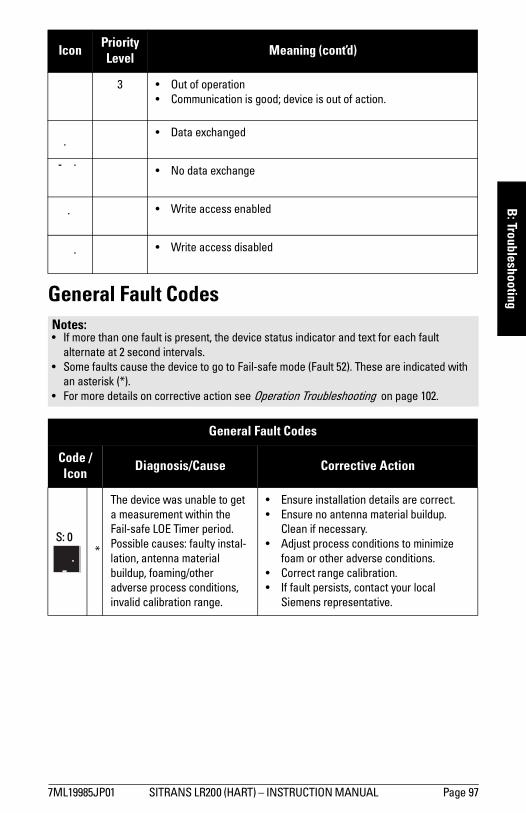
mm
mm
m
B: Troubleshooting
General Fault Codes3 • Out of operation• Communication is good; device is out of action.
• Data exchanged
• No data exchange
• Write access enabled
• Write access disabled
Notes: • If more than one fault is present, the device status indicator and text for each fault
alternate at 2 second intervals.• Some faults cause the device to go to Fail-safe mode (Fault 52). These are indicated with
an asterisk (*).• For more details on corrective action see Operation Troubleshooting on page 102.
General Fault Codes
Code /Icon Diagnosis/Cause Corrective Action
S: 0*
The device was unable to get a measurement within the Fail-safe LOE Timer period. Possible causes: faulty instal-lation, antenna material buildup, foaming/other adverse process conditions, invalid calibration range.
• Ensure installation details are correct.• Ensure no antenna material buildup.
Clean if necessary.• Adjust process conditions to minimize
foam or other adverse conditions. • Correct range calibration. • If fault persists, contact your local
Siemens representative.
Icon PriorityLevel Meaning (cont’d)
7ML19985JP01 SITRANS LR200 (HART) – INSTRUCTION MANUAL Page 97

mm
mm
m
B: T
roub
lesh
ootin
g
S: 2*
Unable to collect profile because of a power condition that is outside the operating range of the device.
Repair required. Contact your local Siemens representative.
S: 3Device is nearing its lifetime limit according to the value set in Maintenance Required Limit.
Replacement is recommended.
S: 4Device is nearing its lifetime limit according to the value set in Maintenance Demanded Limit.
Replacement is recommended.
S: 6Sensor is nearing its lifetime limit according to the value set in Maintenance Required Limit.
Replacement is recommended.
S: 7Sensor is nearing its lifetime limit according to the value set in Maintenance Demanded Limit.
Replacement is recommended.
S: 8 Service interval as defined in Maintenance Required Limit has expired.
Perform service.
S: 9 Service interval as defined in Maintenance Demanded Limit has expired.
Perform service.
S: 11 Internal temperature sensor failure.
Repair required: contact your local Siemens representative.
General Fault Codes (cont’d)
Code /Icon Diagnosis/Cause Corrective Action
Page 98 SITRANS LR200 (HART) – INSTRUCTION MANUAL 7ML19985JP01

mm
mm
m
B: Troubleshooting
S: 12Internal temperature of device has exceeded specifications: it is operating outside its tem-perature range.
• Relocate device and/or lower ambient temperature enough to cool device.
• Inspect for heat-related damage and contact your local Siemens representative if repair is required.
• Fault code will persist until a manual reset is performed using PDM or the LCD interface.
S: 17 Calibration interval as defined in Maintenance Required Limit has expired.
Perform calibration.
S: 18 Calibration interval as defined in Maintenance Demanded Limit has expired.
Perform calibration.
S: 28*
Internal device failure caused by a RAM memory error.
Repair required: contact your local Siemens representative.
S: 29* EEPROM damaged.
Repair required: contact your local Siemens representative.
S: 31* Flash error.
Repair required: contact your local Siemens representative.
S: 33*
Factory calibration for the internal temperature sensor has been lost.
Repair required: contact your local Siemens representative.
S: 34*
Factory calibration for the device has been lost.
Repair required: contact your local Siemens representative.
General Fault Codes (cont’d)
Code /Icon Diagnosis/Cause Corrective Action
7ML19985JP01 SITRANS LR200 (HART) – INSTRUCTION MANUAL Page 99

mm
mm
m
B: T
roub
lesh
ootin
g
S: 35*
Factory calibration for the device has been lost.
Repair required: contact your local Siemens representative.
S: 36*
Unable to start microwave module.
Cycle power. If fault persists, contact your local Siemens representative.
S: 37*
Measurement hardware prob-lem.
Cycle power. If fault persists, contact your local Siemens representative.
S: 38*
Microwave module hardware failure: unable to calculate distance measurement.
Cycle power. If fault persists, contact your local Siemens representative: repair required.
S: 43*
Factory calibration for the radar receiver has been lost.
Repair required: contact your local Siemens representative.
S: 45*
No valid boot program detected: firmware corrupt.
Repair required: contact your local Siemens representative.
S: 48 * User configuration is invalid. One or more of parameters: Low Calibration Point, High Calibration Point, and/or Auto False-Echo Suppression, are set to invalid values.
Reconfigure the unit. Ensure the difference between High Calibration Point and Low Cal-ibration Point is not less than or equal to zero; do a master reset.
S: 49 * EEPROM corrupt. Repair required: contact your local Siemens representative.
General Fault Codes (cont’d)
Code /Icon Diagnosis/Cause Corrective Action
Page 100 SITRANS LR200 (HART) – INSTRUCTION MANUAL 7ML19985JP01
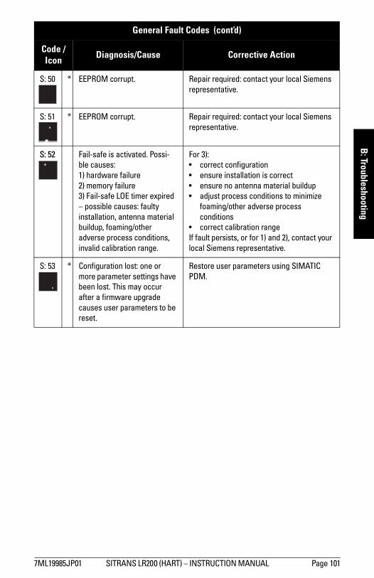
mm
mm
m
B: Troubleshooting
S: 50 * EEPROM corrupt. Repair required: contact your local Siemens representative.
S: 51 * EEPROM corrupt. Repair required: contact your local Siemens representative.
S: 52 Fail-safe is activated. Possi-ble causes: 1) hardware failure2) memory failure3) Fail-safe LOE timer expired – possible causes: faulty installation, antenna material buildup, foaming/other adverse process conditions, invalid calibration range.
For 3):• correct configuration• ensure installation is correct• ensure no antenna material buildup • adjust process conditions to minimize
foaming/other adverse process conditions
• correct calibration rangeIf fault persists, or for 1) and 2), contact your local Siemens representative.
S: 53 * Configuration lost: one or more parameter settings have been lost. This may occur after a firmware upgrade causes user parameters to be reset.
Restore user parameters using SIMATIC PDM.
General Fault Codes (cont’d)
Code /Icon Diagnosis/Cause Corrective Action
7ML19985JP01 SITRANS LR200 (HART) – INSTRUCTION MANUAL Page 101

mm
mm
m
B: T
roub
lesh
ootin
g
Operation TroubleshootingOperating symptoms, probable causes, and resolutions.
Operation Troubleshooting Symptom Cause Action
Display shows S: 0 LOE
level or target is out of range
• check specifications• check Low Calibration Pt. (2.2.1.6.)• increase Echo Confidence (2.2.4.5.1.)
material build-up on antenna
• clean the antenna• re-locate SITRANS LR200
location or aiming:• poor installation• flange not level
• ensure antenna protrudes from end of nozzle
• check to ensure nozzle is vertical
antenna malfunction:• temperature too high• physical damage• excessive foam
• check Current Internal Temperature (3.14.1.) and relocate device
• replace device• use foam deflector or stillpipe, or use a
defoamer
Reading does not change, but the level does
SITRANS LR200 process-ing wrong echo (vessel wall or structural mem-ber)
• re-locate SITRANS LR200• check nozzle for internal burrs or welds• rotate instrument 90°• use Auto False Echo Suppression (2.2.5.2.)
and Auto Suppression Range (2.2.5.3.)
Measurement is consistently off by a constant amount
• setting for Low Calibration Pt. (2.2.1.6.) not correct
• setting for Sensor Offset (2.2.1.20.) not correct
• check distance from sensor reference point to Low Calibration Pt. (2.2.1.6.)
• check Sensor Offset (2.2.1.20.)
Screen blank
power error• check nameplate rating against voltage
supply• check power wiring or source
too much load resistance• change barrier type, or• remove something from the loop, or• increase supply voltage
Page 102 SITRANS LR200 (HART) – INSTRUCTION MANUAL 7ML19985JP01

mm
mm
m
B: Troubleshooting
Reading erratic
echo confidence weak
• refer to Echo Confidence (2.2.4.5.1.)• use Auto False Echo Suppression (2.2.5.2.)
and Auto Suppression Range (2.2.5.3.) • use foam deflector or stillpipe
liquid surface vortexed
• decrease Fill Rate (2.2.7.2.) • relocate instrument to side pipe• increase confidence threshold in Echo
Threshold (2.2.4.1.3.)material filling • re-locate SITRANS LR200
Reading response slow
Fill Rate (2.2.7.2.) setting incorrect
• increase measurement response if possible
Reads correctly but occasionally reads high when vessel is not full
• detecting close range echo
• build up near top of vessel or nozzle
• nozzle problem
• clean the antenna• use Auto False Echo Suppression (2.2.5.2.)
and Auto Suppression Range (2.2.5.3.)
Level reading lower than mate-rial level
• material is within Near Range zone
• decrease Near Range (2.2.1.11.) (minimum value depends on antenna type)
• raise SITRANS LR200• vessel near empty and
low dK material • ensure Material (2.2.1.2.) selection is
LIQUID LOW DK, Position (2.2.4.1.2.) is set to Hybrid, and CLEF Range (2.2.4.4.3.) is set to 0.5 m
Operation Troubleshooting (cont’d)Symptom Cause Action (cont’d)
7ML19985JP01 SITRANS LR200 (HART) – INSTRUCTION MANUAL Page 103

Page 104 SITRANS LR200 (HART) – INSTRUCTION MANUAL 7ML19985JP01
mm
mm
m
C: M
aint
enan
ce
Appendix C: Maintenance
SITRANS LR200 requires no maintenance or cleaning under normal operating conditions.
Under severe operating conditions, the antenna may require periodic cleaning. If cleaning becomes necessary:• Note the antenna material and the process medium, and select a cleaning solution
that will not react adversely with either.• Remove the instrument from service and wipe the antenna clean using a cloth and
suitable cleaning solution.
Unit Repair and Excluded LiabilityAll changes and repairs must be done by qualified personnel, and applicable safety regulations must be followed. Please note the following:
• The user is responsible for all changes and repairs made to the device.• All new components must be provided by Siemens Milltronics Process Instruments Inc.• Restrict repair to faulty components only.• Do not re-use faulty components.
Replacing the antenna• When a new antenna is installed the propagation factor will not change.• After replacing the antenna check the material level reported by the device against
the actual material level, and if necessary use Sensor Offset (2.2.1.20.) on page 55 to compensate.

mm
mm
m
D: Technical Reference
Appendix D: Technical Reference
Principles of Operation SITRANS LR200 is a sophisticated radar instrument that uses advanced microwave pulse technology1) to provide non-contacting continuous level measurement in liquids or slurries. Radar level measurement uses the time of flight principle to determine distance to a material surface. The device transmits a signal and waits for the return echo. The transit time is directly proportional to the distance from the material.
Pulse radar uses polarized electromagnetic waves. Microwave pulses are emitted from the antenna at a fixed repetition rate, and reflect off the interface between two materials with different dielectric constants (the atmosphere and the material being monitored).
Electromagnetic wave propagation is virtually unaffected by temperature or pressure changes, or by changes in the vapor levels inside a vessel. Electromagnetic waves are not attenuated by dust.
SITRANS LR200 consists of an enclosed electronic circuit coupled to an antenna and process connection. The electronic component generates a radar signal (6.3 GHz in North America, 5.8 GHz elsewhere) that is directed to the antenna.
The signal is emitted from the antenna, and the reflected echoes are digitally converted to an echo profile. The profile is analyzed to determine the distance from the material
surface to the sensor reference point2). This distance is used as a basis for the display of material level and mA output.
Echo Processing
Process IntelligenceThe signal processing technology embedded in Siemens radar level devices is known as Process Intelligence.
Process intelligence provides high measurement reliability regardless of the dynamically changing conditions within the vessel being monitored. The embedded Process Intelligence dynamically adjusts to the constantly changing material surfaces within these vessels.
1) The microwave output level is significantly less than that emitted from cellular phones.
2) See Dimensions: Uni-Construction Polypropylene Rod Antenna on page 12 or Appen-dix G: Flange Adapter Versions on page 128 onwards.
7ML19985JP01 SITRANS LR200 (HART) – INSTRUCTION MANUAL Page 105
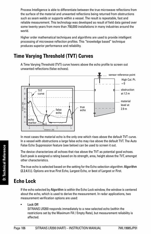
mm
mm
m
D: T
echn
ical
Ref
eren
ce
Process Intelligence is able to differentiate between the true microwave reflections from the surface of the material and unwanted reflections being returned from obstructions such as seam welds or supports within a vessel. The result is repeatable, fast and reliable measurement. This technology was developed as result of field data gained over some twenty years from more than 750,000 installations in many industries around the world.Higher order mathematical techniques and algorithms are used to provide intelligent processing of microwave reflection profiles. This “knowledge based” technique produces superior performance and reliability.
Time Varying Threshold (TVT) CurvesA Time Varying Threshold (TVT) curve hovers above the echo profile to screen out unwanted reflections (false echoes).
In most cases the material echo is the only one which rises above the default TVT curve. In a vessel with obstructions a large false echo may rise above the default TVT. The Auto False Echo Suppression feature (see below) can be used to screen it out.
The device characterizes all echoes that rise above the TVT as potential good echoes. Each peak is assigned a rating based on its strength, area, height above the TVT, amongst other characteristics.
The true echo is selected based on the setting for the Echo selection algorithm: Algorithm (2.2.4.1.1.). Options are true First Echo, Largest Echo, or best of Largest or First.
Echo LockIf the echo selected by Algorithm is within the Echo Lock window, the window is centered about the echo, which is used to derive the measurement. In radar applications, two measurement verification options are used:
• Lock Off: SITRANS LR200 responds immediately to a new selected echo (within the
restrictions set by the Maximum Fill / Empty Rate), but measurement reliability is affected.
Distance [M]0 1 2 3
Pro
file
[dB
]0
10
20
30
40
50
60
70
High Cal. Pt.= 0
obstruction at 1.2 m
material level at 2.9 m
echo marker
false echo
true echo
TVT curve
sensor reference point
Page 106 SITRANS LR200 (HART) – INSTRUCTION MANUAL 7ML19985JP01

mm
mm
m
D: Technical Reference
• Material Agitator: A new measurement outside the Echo Lock Window must meet the sampling
criteria before the window will move to include it.
The other available options, Maximum Verification and Total Lock are not recommended for radar.
Echo Position DetectionThe echo position algorithm Position (2.2.4.1.2.) determines which point on the echo will be used to calculate the precise time of flight, and calculates the range using the calibrated propagation velocity (adjusted by a propagation factor, if necessary).
The options are Center or CLEF (Constrained Leading Edge Fit). CLEF uses the leading edge of the echo. It can be used to compensate for materials with a low dK value, which may cause the vessel bottom to be reported as the level instead of the actual material level, in low level conditions. CLEF range is the level below which the CLEF algorithm will be used: above this level the Center algorithm is used.
Hybrid uses a combination of Center and CLEF, depending on the setting for CLEF range.
Auto False Echo SuppressionIf an obstruction is causing a large echo before the material level echo, that echo will rise above the default TVT curve and may be selected as the true echo. Auto False-Echo Suppression modifies the TVT curve so that the false echo will not rise above the TVT curve.
When you use Auto False Echo Suppression, the device first learns the echo profile at that moment. A learned TVT curve follows the echo profile and rises above the false echo. You set Auto Suppression Range so that the learned profile replaces the default TVT curve up to a point past the obstruction. From that point on, the default TVT curve is used. The material level echo rises above this, and is selected as the true echo.
Example after Auto False Echo Suppression learned
TVT curve
liquid level
Leve
l (db
)
false echo
echo marker
7ML19985JP01 SITRANS LR200 (HART) – INSTRUCTION MANUAL Page 107

mm
mm
m
D: T
echn
ical
Ref
eren
ce
Measurement Range
Near RangeNear Range (2.2.1.11.) programs SITRANS LR200 to ignore the zone in front of the antenna. The default blanking distance is 50 mm (1.97") from end of horn antenna.
Near Range allows you to increase the blanking value from its factory default. But Auto False Echo Suppression (2.2.5.2.) is generally recommended in preference to extending the blanking distance from factory values.
Far RangeIn applications where the base of the vessel is conical or parabolic, a reliable echo may be available below the vessel empty distance, due to an indirect reflection path. Increasing the range extension to 30% or 40% can provide stable empty vessel readings.
Measurement ResponseThe measurement response (response rate) limits the maximum rate at which the display and output respond to changes in the measurement. Once the real process fill/empty rate (m/s) is established, a response rate can be selected that is slightly higher than the application rate. The response rate automatically adjusts the filters that affect the output response rate.
There are three preset options: slow, medium, and fast.
mA OutputThe mA output is proportional to the level, in the range 4 to 20 mA. Generally, the output is set so that the output for 0% is 4 mA, and the output for 100% is 20 mA. 0 and 100% are percentages of the full-scale reading (m, cm, mm, ft, in).
Fill Rate (2.2.7.2.)
Fill Rate (2.2.7.2.)/Empty rate (2.2.7.3.)
Echo Lock (2.2.4.2.1.)
Fail-safe Timer (2.4.1.)
(time in min.)
Slow * 0.1 m/min MATLAGITATOR 100
Medium 1 m/min MATLAGITATOR 10
Fast 10 m/min MATLAGITATOR 1
Page 108 SITRANS LR200 (HART) – INSTRUCTION MANUAL 7ML19985JP01

mm
mm
m
D: Technical Reference
When SITRANS LR200 is put into PROGRAM mode it stops responding to the process. It stores the most recent measurement, and holds the associated readings and mA signal output. The instrument reverts to the parameter last addressed during the previous program session.
When the instrument is returned to Measurement mode, the transceiver resumes operation. The reading and mA output default to the last measurement taken. The reading and associated outputs migrate to the current process level at a rate controlled by the response rate (2.2.7.1).
If SITRANS LR200 is left in PROGRAM mode for 10 minutes without input, it automatically reverts to Measurement mode.
DampingA damping filter smooths out the response to a sudden change in level. This is an exponential filter and the engineering unit is always in seconds. The setting can be modified in Damping Filter (2.2.4.3.2.).
Damping example
Level Space Distance
Distance
Space
Level
20 mA100%
0%4 mA
HighCal.Point
4 mA0%
100% 20 mA
4 mA0%
100% 20 mA
Sensorreferencepoint
LowCal.Point
0
0.5
1
1.5
2
2.5
3
3.5
4
4.5
1 2 3 4 5 6 7
Series1 Series2
time constant = 2 seconds
input (level) change = 2 m
In 5 time constants the output rises exponentially:from 63.2% of the change in the first time constant, to almost 100% of the change by the end of the 5th time constant.
Level (m)
Time (s)
smoothed outputinput (level)
7ML19985JP01 SITRANS LR200 (HART) – INSTRUCTION MANUAL Page 109

mm
mm
m
D: T
echn
ical
Ref
eren
ce
Loss of Echo (LOE)A loss of echo (LOE) occurs when the calculated measurement is judged to be unreliable because the echo confidence value has dropped below the echo confidence threshold.
If the LOE condition persists beyond the time limit set in Fail-safe Timer (2.4.1.) the LCD displays the Service Required icon, and the text region displays the fault code S: 0 and the error message LOE.
If two faults are present at the same time, the fault code, error text, and error icon for each fault are displayed alternately. For example, Loss of Echo and Fail-safe High.
S: 0 LOE S: 52 FAIL-SAFE
Fail-safe ModeThe purpose of the Fail-safe setting is to put the process into a safe mode of operation in the event of a fault or failure. The value to be reported in the event of a fault is selected so that a loss of power or loss of signal triggers the same response as an unsafe level.
Fail-safe TimerFail-safe Timer determines the time to elapse after the last valid reading before a Fail-safe state is activated. Fail-safe Material Level determines the level to be reported when the Fail-safe timer expires. Upon receiving a reliable echo, the loss of echo condition is aborted, the Service Required icon and error message are cleared, and the reading and mA output return to the current level.
Fail-safe valueWhen the Fail-safe Timer (2.4.1.) expires, the material level to be reported is determined by Fail-safe Material Level (2.4.2.).
Fail-safe Material LevelHI Use Maximum mA Limit as material levelLO Use Minimum mA Limit as material level
HOLD Level remains at last readingVALUE User-selected value
Page 110 SITRANS LR200 (HART) – INSTRUCTION MANUAL 7ML19985JP01

mm
mm
m
D: Technical Reference
Maximum Process Temperature Chart
.
Where the chart does not apply, please use your own judgement regarding the use of SITRANS LR200.
See Current Internal Temperature (3.14.1) to monitor the internal temperature.
If the internal temperature exceeds the maximum allowable limit, a sun shield or a longer nozzle may be required.
WARNING: Internal temperature must not exceed 80 oC (176 oF). Note: The chart below is for guidance only:
Maximum Flange and Process Temperatures versus Allowable Ambient for Polypropylene Rod or Flange Adaptor versions of SITRANS LR200
flange temperature
process temperatureA
mbi
ent T
empe
ratu
re (o C)
Process Flange Surface Temperature (oC)
polypropylene rod temperature (no flange)
• The chart does not represent every possible process connection arrangement. For example, it will NOT apply if you are mounting SITRANS LR200 on a nozzle greater than 8” nominal, or directly on a metallic vessel surface.
• The chart does not take into consideration heating from direct sunshine exposure.
ambient temperature
process temperature
internal enclosure temperature
7ML19985JP01 SITRANS LR200 (HART) – INSTRUCTION MANUAL Page 111

mm
mm
m
D: T
echn
ical
Ref
eren
ce
Process Pressure/Temperature derating curves1)
WARNINGS: • Never attempt to loosen, remove or disassemble process connection
or instrument housing while vessel contents are under pressure.• This product is designated as a Pressure Accessory per Directive 97/ 23 / EC
and is not intended for use as a safety device.• Materials of construction are chosen based on their chemical
compatibility (or inertness) for general purposes. For exposure to specific environments, check with chemical compatibility charts before installing.
• The user is responsible for the selection of bolting and gasket materials which will fall within the limits of the flange and its intended use and which are suitable for the service conditions.
• Improper installation may result in loss of process pressure.Notes: • The Process Device Tag shall remain with the process pressure boundary
assembly1). In the event the instrument package is replaced, the Process Device Tag shall be transferred to the replacement unit.
• SITRANS LR200 units are hydrostatically tested, meeting or exceeding the requirements of the ASME Boiler and Pressure Vessel Code and the European Pressure Equipment Directive.
• The serial numbers stamped in each process connection body, (flange, threaded, or sanitary), provide a unique identification number indicating date of manufacture.Example: MMDDYY – XXX (where MM = month, DD = day, YY = year, and
XXX= sequential unit produced) • Further markings (space permitting) indicate flange configuration, size, pressure
class, material, and material heat code.
1) The process pressure boundary assembly comprises the components that act as a barrier against pressure loss from the process vessel: that is, the combination of process connection body and emitter, but normally excluding the electrical enclosure.
Page 112 SITRANS LR200 (HART) – INSTRUCTION MANUAL 7ML19985JP01

mm
mm
m
D: Technical Reference
PTFE Rod Antenna ANSI Hole Pattern, 150#1), 2)
PTFE Rod Antenna DN Hole Pattern, PN161), 2)
1) UHMW-PE antennas are rated to a maximum of 80°C (176°F) of continuous duty, how-ever, they can be used for periods of up to 3 hours at temperatures up to 120°C (248°F) at 1 bar pressure.
2) Customer to provide adequate bolting to retain vessel pressure and provide sufficient sealing.
WARNING: Never attempt to loosen, remove or disassemble process connection or instrument housing while vessel contents are under pressure.
Process Configuration:• 51003 with flange series 22452.• Flange will be stamped
22452. Process connection tag will have the series identified as 51003.
• Reference drawing number is shown on the process device tag. You can find this drawing on our website: www.siemens.com/processautomation, on the LR200 product page, under Process Connection Specifications.
2” 3”4” 6”
process temperature (°C)
pres
sure
(bar
, gau
ge)
pres
sure
(ba
r, g
auge
)
100 mm50 mm
150 mm80 mm
process temperature (°C)
Process Configuration:• 51003 with flange series
22452.• Flange will be stamped
22452. Process connection tag will have the series identified as 51003.
• Reference drawing number is shown on the process device tag. You can find this drawing on our website: www.siemens.com/processautomation, on the LR200 product page, under Process Connection
7ML19985JP01 SITRANS LR200 (HART) – INSTRUCTION MANUAL Page 113

mm
mm
m
D: T
echn
ical
Ref
eren
ce
PTFE Rod Antenna Threaded Connection
PTFE Rod Antenna Sanitary Connection1)
WARNING: Never attempt to loosen, remove or disassemble process connection or instrument housing while vessel contents are under pressure.
1) UHMW-PE antennas are rated to a maximum of 80°C (176°F) of continuous duty; however, they can be used for periods of up to 3 hours at temperatures up to 120°C (248°F) at 1 bar pressure.
Process Connection Series:• 51002, 51004, 51005• Ensure the instrument has a
process connection identification tag showing one of this series.
• Reference drawing number is shown on the process device tag. You can find this drawing on our website: www.siemens.com/processautomation on the LR200 product page, under Process Connection Specifications.
1 1/2” and 2"
pres
sure
(bar
, gau
ge)
process temperature (°C)
0.01.02.03.04.05.06.07.08.09.0
-100 -50 0 50 100 150 200 250
2", 3" & 4"
pres
sure
(ba
r, g
auge
)
Process Connection Series:• 51010• Ensure instrument has the
process identification tag showing this series number.
• Reference drawing number is shown on the process device tag. You can find this drawing on our website: www.siemens.com/processautomation, on the LR200 product page, under Process Connection Specifications.
process temperature (°C)
Page 114 SITRANS LR200 (HART) – INSTRUCTION MANUAL 7ML19985JP01

mm
mm
m
D: Technical Reference
Horn Antenna or Wave Guide – ANSI Hole Pattern, 150#1)
Horn Antenna or Wave Guide DN Hole Pattern, PN161)
1) Customer to provide adequate bolting and flat-faced gasket to retain vessel pressure and provide sufficient sealing.
WARNING: Never attempt to loosen, remove or disassemble process connection or instrument housing while vessel contents are under pressure.
Process Connection Series:• 51006 to 51008, and 51010 to
51012, with 22452 series flange.
• Ensure your instrument has the process identification tag showing one of this series, and 22452 stamped on flange.
• Reference drawing number is shown on the process device tag. You can find this drawing on our website: www.siemens.com/processautomation on the LR200 product page, under Process Connection Specifications.
process temperature (°C)
pres
sure
(bar
, gau
ge)
4”63”
8”
50
2.0
4.0
6.0
8.0
10.0
12.0
14.0
16.0
18.0
0-50 100 150 200
Process Connection Series:• 51006 to 51008, and 51010 to
51012 with 22452 series flange.
• Ensure your instrument has the process identification tag showing one of this series, and 22452 stamped on flange.
• Reference drawing number is shown on the process device tag. You can find this drawing on our website: www.siemens.com/processautomation on the LR200 product page, under Process Connection Specifications.
process temperature (°C)100 mm
150 mm 200 mm80 mm
pres
sure
(bar
, gau
ge)
7ML19985JP01 SITRANS LR200 (HART) – INSTRUCTION MANUAL Page 115

mm
mm
m
D: T
echn
ical
Ref
eren
ce
Loop powerTypical Connection Drawing
Curve 1 (General Purpose, Intrinsically Safe, Non-incendive)
Note: Loop voltage is the voltage at the terminals of the power supply (not the voltage at the terminals of the device).
+
-
loop resistance RL
loop current IL
loop voltageVL
power supply
LR200
Power Supply Requirements
0
100
200
300
400
500
600
700
800
900
15 17 19 21 23 25 27 29
Loop Voltage - VL
(Source Voltage)
Lo
op
Re
sis
tan
ce
-R
L
(30.0V, 845 ohms)
RL = 44.6 * VL - 493.4
(17.8V, 300 ohms)
(16.7V, 0 ohms)
RL = 272.7 * VL - 4554.1
Loop Voltage versus Loop Resistance
Loop Voltage – VL
Loop
Res
ista
nce
– R L
ALLOWABLE OPERATING AREA
Power Supply Requirements
Page 116 SITRANS LR200 (HART) – INSTRUCTION MANUAL 7ML19985JP01

mm
mm
m
D: Technical Reference
Curve 2 (Flameproof, Increased Safety, Explosion-proof)
Startup Curve
Note: At startup, it can take anywhere from 25 to 55 seconds for the device to report the actual material level.
Loop Voltage versus Loop Resistance
Power Supply Requirements
0
50
100
150
200
250
300
350
400
15 20 25 30
Loop Voltage - VL
(Source Voltage)
Lo
op
Re
sis
tan
ce
-R
L
(30.0V, 375 ohms)
RL = 14.88 * VL - 71.43
(21.6V, 250 ohms)
(18.2V, 0 ohms)
RL = 73.53 * VL - 1338.24
Power Supply Requirements
Loop Voltage – VL
Loop
Res
ista
nce
– R L
ALLOWABLE OPERATING AREA
0
5
10
15
20
25
30
35
40
0 5 10 15 20 25 30 35 40 45 50 55
Time (secs)
Cu
rre
nt
(mA
)
No Current Limit Current Limited Power Supply
Curr
ent (
mA
)
Time (seconds)No current limit Current-limited power
Loop Power Supply (no Current Limit)
Loop Power Supply with 25 mA Current Limit
actual material level (example value 18 mA )
7ML19985JP01 SITRANS LR200 (HART) – INSTRUCTION MANUAL Page 117

mm
mm
m
E: S
peci
al A
pplic
atio
ns
Appendix E: Application ExamplesYou can use these examples as setup references. Enter the values in the parameter tables to select the corresponding functions.
Liquid resin in storage vessel, level measurementNotes: • The minimum distance from the flange face to the target is limited by Near Range
(2.2.1.11.).• We recommend adjusting Auto False Echo Suppression parameters with an empty
or almost empty vessel.
Parameter type
Parameter Name (number) Value Function
Quick start wizardparameters
Material (1.1.) LIQUID
Response Rate (1.2.) MED 1 m/minute
Sensor Units (1.3.) M meters
Operation (1.4.) LEVEL Level
Low Calibration Point (1.5.) 5 5 m
High Calibration Point (1.6.) 0.5 0.5 m
Apply? (Apply changes) (1.7.) YES
Other parameters
Fail-safe Timer (2.4.1.) 2 2 minutes
Fail-safe Material Level (2.4.2.) HI Hi
• The application is to obtain a level measurement and corresponding 4 to 20 mA output proportional to resin levels in a storage vessel.
• Low Calibration Point is the vessel bottom (5 m (16.5 ft) from the sensor reference point).
• High Calibration Point is 0.5 m (1.64 ft) from the sensor reference point.
• The maximum rate of filling or emptying is about 0.2 m/min.
• In the event of a loss of echo, SITRANS LR200 is to go into Fail-safe Hi after 2 minutes.
0.5 m
Low Cal Point
5 m
100% Level
0% Level
HighCalPoint
Sensorreferencepoint
Page 118 SITRANS LR200 (HART) – INSTRUCTION MANUAL 7ML19985JP01
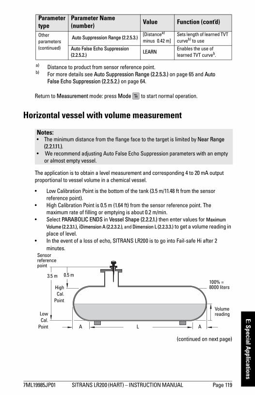
mm
mm
m
E: Special Applications
Return to Measurement mode: press Mode to start normal operation.
Horizontal vessel with volume measurement
The application is to obtain a level measurement and corresponding 4 to 20 mA output proportional to vessel volume in a chemical vessel.
• Low Calibration Point is the bottom of the tank (3.5 m/11.48 ft from the sensor reference point).
• High Calibration Point is 0.5 m (1.64 ft) from the sensor reference point. The maximum rate of filling or emptying is about 0.2 m/min.
• Select PARABOLIC ENDS in Vessel Shape (2.2.2.1.) then enter values for Maximum Volume (2.2.3.1.), iDimension A (2.2.3.2.), and Dimension L (2.2.3.3.) to get a volume reading in place of level.
• In the event of a loss of echo, SITRANS LR200 is to go into Fail-safe Hi after 2 minutes.
(continued on next page)
Other parameters (continued)
Auto Suppression Range (2.2.5.3.)[Distancea) minus 0.42 m]
Sets length of learned TVT curveb) to use
Auto False Echo Suppression (2.2.5.2.)
LEARNEnables the use of learned TVT curveb.
a) Distance to product from sensor reference point.b) For more details see Auto Suppression Range (2.2.5.3.) on page 65 and Auto
False Echo Suppression (2.2.5.2.) on page 64.
Notes: • The minimum distance from the flange face to the target is limited by Near Range
(2.2.1.11.).• We recommend adjusting Auto False Echo Suppression parameters with an empty
or almost empty vessel.
Parameter type
Parameter Name (number) Value Function (cont’d)
Volume reading
0.5 m 3.5 m
A AL
HighCal.
Point
LowCal.
Point
100% = 8000 liters
Sensor reference point
7ML19985JP01 SITRANS LR200 (HART) – INSTRUCTION MANUAL Page 119
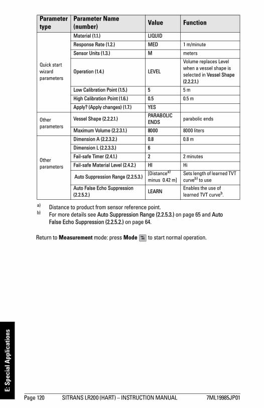
mm
mm
m
E: S
peci
al A
pplic
atio
ns
Return to Measurement mode: press Mode to start normal operation.
Parameter type
Parameter Name (number) Value Function
Quick start wizardparameters
Material (1.1.) LIQUID
Response Rate (1.2.) MED 1 m/minute
Sensor Units (1.3.) M meters
Operation (1.4.) LEVEL
Volume replaces Level when a vessel shape is selected in Vessel Shape (2.2.2.1.)
Low Calibration Point (1.5.) 5 5 m
High Calibration Point (1.6.) 0.5 0.5 m
Apply? (Apply changes) (1.7.) YES
Other parameters
Vessel Shape (2.2.2.1.)PARABOLIC ENDS
parabolic ends
Maximum Volume (2.2.3.1.) 8000 8000 liters
Other parameters
Dimension A (2.2.3.2.) 0.8 0.8 m
Dimension L (2.2.3.3.) 6
Fail-safe Timer (2.4.1.) 2 2 minutes
Fail-safe Material Level (2.4.2.) HI Hi
Auto Suppression Range (2.2.5.3.)[Distancea) minus 0.42 m]
Sets length of learned TVT curveb) to use
Auto False Echo Suppression (2.2.5.2.)
LEARNEnables the use of learned TVT curveb.
a) Distance to product from sensor reference point.b) For more details see Auto Suppression Range (2.2.5.3.) on page 65 and Auto
False Echo Suppression (2.2.5.2.) on page 64.
Page 120 SITRANS LR200 (HART) – INSTRUCTION MANUAL 7ML19985JP01

mm
mm
m
E: Special Applications
Sliding Waveguide on Anaerobic Digesters
This application is to obtain a level measurement and corresponding 4 to 20 mA output
proportional to the sludge level on a digester.
Notes: • Minimum distance from the flange face to the target is limited by Near Range
(2.2.1.11.).• We recommend adjusting Auto False Echo Suppression parameters with an empty
or almost empty vessel.
Note: Table continues on next page.
Parame-ter type
Parameter Name (number) Value Function
Quick start wizardparameters
Material (1.1.) LIQUID
Response Rate (1.2.) MED 1 m/minute
Sensor Units (1.3.) M meters
Operation (1.4.) LEVEL Level
Low Calibration Point (1.5.) 10 10 m
High Calibration Point (1.6.) 2 2 m
Apply? (Apply changes) (1.7.) YES
2 m
10 m
horn
• The raised position is for installation and maintenance.
• The lowered position is for operation.• Program the instrument for operation
in the lowered position.
• Low Cal. Pt. is the bottom of the digester (10 m/33 ft from sensor reference point when the instrument is lowered to its normal operating position).
• High Cal.Pt. is 2 m (6.56 ft) from sensor reference point.
• The maximum rate of filling or emptying is about 0.1 m (4")/min.
High Cal. Point
Low Cal. Point
sensor reference point
7ML19985JP01 SITRANS LR200 (HART) – INSTRUCTION MANUAL Page 121

mm
mm
m
E: S
peci
al A
pplic
atio
ns
Return to Measurement mode: press Mode to start normal operation.
Stillpipe Application This is an alternative to the waveguide antenna option, used for products with a dK of less than 3, or if extremely turbulent or vortex conditions exist. This mounting arrangement can also be used to provide optimum signal conditions on foaming materials.
This application is to obtain a level measurement and corresponding 4 to 20 mA output proportional to the oil level in a fuel storage vessel.
Other parameters
Fail-safe Timer (2.4.1.) 2 2 minutes
Fail-safe Material Level (2.4.2.) HI Hi
Auto Suppression Range (2.2.5.3.)[Distancea) minus 0.42 m]
Sets length of learned TVT curveb) to use
Auto False Echo Suppression (2.2.5.2.)
LEARNEnables the use of learned TVT curveb.
a) Distance to product from sensor reference point.b) For more details see Auto Suppression Range (2.2.5.3.) on page 65 and Auto
False Echo Suppression (2.2.5.2.) on page 64.
Notes: • For dK < 3, the lower 400 mm of vessel level may not be measurable.• Near Range (2.2.1.11.)will be set at the factory. Check the process device tag for
specific values.• Suitable pipe diameters are 50 mm (2”) to 250 mm (10”). See Propagation Factor
(2.2.1.14.) on page 54 for typical values.• We recommend adjusting Auto False Echo Suppression parameters with an empty
or almost empty vessel.
Parame-ter type
Parameter Name (number) Value Function (cont’d)
• Low Calibration Point is the vessel bottom (5 m (16.5 ft) from the sensor reference point).
• High Calibration Point is 0.5 m (1.64 ft) from the sensor reference point.
• The stillpipe inside diameter is 100 mm (4").
• The maximum rate of filling or emptying is about 0.1 m (4")/min.
• In the event of a loss of echo, SITRANS LR200 is to go into Fail-safe Hi after 2 minutes.
100 mm (4”) diameter
vent hole
5 m
0.5 m
HighCal. Pt.
Low Cal. Pt.
sensor reference pt.
Page 122 SITRANS LR200 (HART) – INSTRUCTION MANUAL 7ML19985JP01

mm
mm
m
E: Special Applications
Return to Measurement mode: press Mode to start normal operation.
Parameter type
Parameter Name (number) Value Function
Quick start wizardparameters
Material (1.1.)LIQUID LOW DK
Response Rate (1.2.) MED 1 m/minute
Sensor Units (1.3.) M meters
Operation (1.4.) LEVEL Level
Low Calibration Point (1.5.) 5 5 m
High Calibration Point (1.6.) 0.5 0.5 m
Apply? (Apply changes) (1.7.) YES
Other parameters
Fail-safe Timer (2.4.1.) 2 2 minutes
Fail-safe Material Level (2.4.2.) HI Hi
Other parameters
Auto Suppression Range (2.2.5.3.)[Distancea) minus 0.42 m]
a) Distance to product from sensor reference point.
Sets length of learned TVT curveb) to use
b) For more details see Auto Suppression Range (2.2.5.3.) on page 65 and Auto False Echo Suppression (2.2.5.2.) on page 64.
Auto False Echo Suppression (2.2.5.2.)
LEARNEnables the use of learned TVT curveb.
Propagation Factor (2.2.1.14.)Depends on pipe diameter: see table on page 54.
7ML19985JP01 SITRANS LR200 (HART) – INSTRUCTION MANUAL Page 123

mm
mm
m
F: H
ART
Com
mun
icat
ions
Appendix F: HARTHART CommunicationHighway Addressable Remote Transducer, HART, is an industrial protocol that is superimposed on the 4-20 mA signal. It is an open standard, and full details about HART can be obtained from the HART Communication Foundation at www.hartcomm.org
SITRANS LR200 Rev 3 can be configured over the HART network using either the HART Communicator 3751) by Fisher-Rosemount, or a software package. There are a number of different software packages available. The recommended software package is the SIMATIC Process Device Manager (PDM) by Siemens.
SIMATIC PDMThis software package is designed to permit easy configuration, monitoring, and troubleshooting of HART devices. The HART DD for SITRANS LR200 was written with SIMATIC PDM in mind and has been extensively tested with this software.
For more information, see Operating via SIMATIC PDM on page 34.
HART Device Description (DD)
In order to configure a HART device, the configurator must have the HART Device Description for the device in question. HART DDs are controlled by the HART Communication Foundation.
Please check with the HART Communication Foundation for the availability of the HART DD for SITRANS LR200. Older versions of the library will have to be updated in order to use all the features of SITRANS LR200.
1) Versions of SITRANS LR200 earlier than Rev. 3 can be configured using the HART Commu-nicator 275.
Note: SITRANS LR200 HART cannot be configured using a generic DD.
Page 124 SITRANS LR200 (HART) – INSTRUCTION MANUAL 7ML19985JP01

mm
mm
m
F: HART Com
munications
HART Communicator 375 Menu Structure
QUICK STARTMATERIALRESPONSE RATESENSOR UNITSOPERATIONLOW CALIB. PT.HIGH CALIB. PT.APPLY?
SETUPDEVICE
SOFTWARE REVLOADER REVHARDWARE REV
INPUTSENSOR CALIB.
MATERIALSENSOR UNITSOPERATIONLOW CALIB. PT.HIGH CALIB. PT.NEAR RANGEFAR RANGEPROPAG. FACTORSENSOR OFFSET
VOL CONVERSIONVESSEL SHAPE
VOLUME BREAKPTMAX. VOLUMEDIMENSION ADIMENSION LTABLE 1 – 8 (Lev./Vol. Breakpoints 1-8)TABLE 9 – 16 (Lev./Vol. Breakpoints 9-16)TABLE 17 – 24 (Lev./Vol. Breakpoints 17-24)TABLE 25 – 32 (Lev./Vol. Breakpoints 25-32)
ECHO PROC.ECHO SELECTALGORITHMPOSITIONECHO THRESHOLDSAMPLINGECHO LOCKUP SAMP. DOWN SAMP. WINDOWFILTERINGDAMPING FILTERTANK BOTTOM ALG
CLEF RANGE
Notes: • HART Communicator 375 is supported by SITRANS LR200 HART Rev. 3.03. The menu
structure is aligned with the menu structure of SIMATIC PDM.• HART Communicator 275 is no longer supported by SITRANS LR200 HART Rev. 3.03.
7ML19985JP01 SITRANS LR200 (HART) – INSTRUCTION MANUAL Page 125

mm
mm
m
F: H
ART
Com
mun
icat
ions
ECHO PROC (continued)NOISE
CONFIDENCESTRENGTHNOISE AVERAGE
TVT SETUPTVT HOVER LEVELAUTO ECHO SUPPAUTO SUPP RANGESHAPER MODE
TVT SHAPERSHAPER 1-9(Shaper Points 1-9)SHAPER 10-18 (Shaper Points 10-18)SHAPER 19-27 (Shaper Points 19-27)SHAPER 28-36 (Shaper Points 28-36)SHAPER 37-40 (Shaper Points 37-40)
RATERESPONSE RATEFILL RATE/minEMPTY RATE/min
TB VALUESREADING MEAS.LEVEL MEAS.SPACE MEAS.DISTANCE MEAS.VOLUME MEAS.
OUTPUTMA OUTPUT
MA OUTPUT VALUEMA OUTPUT FUNC.4 MA SETPOINT20 MA SETPOINTMIN. MA LIMITMAX. MA LIMIT4 MA OUTPUT TRIM20 MA OUTPUT TRIM
FAIL-SAFEFAILSAFE TIMERFAILSAFE MAT. LEVELFAILSAFE LEVEL
DIAGNOSTICSECHO PROFILEMEAS. VALUES
CURR. INTERN. TEMP.MAX. INTERN. TEMP.MIN. INTERN TEMP.
REMAIN. DEV. LIFETOTAL OP--TIMEREMAIN. LIFETIMEMAINT REQ LIMITMAINT DEM LIMITALERT ACTIVATIONTOTAL EXP. LIFEMAINT STATACK STATUSACK
Page 126 SITRANS LR200 (HART) – INSTRUCTION MANUAL 7ML19985JP01

mm
mm
m
F: HART Com
munications
DIAGNOSTICS (continued)REMAIN. SENS. LIFE
SENS OP--TIMEREMAIN. LIFETIMEMAINT REQ LIMITMAINT DEM LIMITALERT ACTIVATIONTOTAL EXP. LIFEMAINT STATACK STATUSACK
SERVICEDEVICE RESETMANUF. DATELCD FAST MODELCD CONTRASTPOWERED HOURSPOWERON RESETSMEM. TESTSERVICE INTERVAL
TIME LAST SERVREMAIN LIFETIMEMAINT REQ LIMITMAINT DEM LIMITALERT ACTIVATIONSERVICE INTERVALMAINT STATACK STATUSACK
CALIB. INTERVALTIME LAST CAL.REMAIN LIFETIMEMAINT REQ LIMITMAINT DEM LIMITALERT ACTIVATIONTOTAL CALIB.INTRVMAINT STATACK STATUSACK
COMMUNICATIONDEVICE ADDRESSCOMM. CONTROL
SECURITYLOCKUNLOCK VALUE
LANGUAGE
HART VersionSITRANS LR200 conforms to HART rev. 5.
Burst ModeSITRANS LR200 does not support burst mode.
HART Multidrop ModeWe do not recommend the use of HART Multidrop Mode.
7ML19985JP01 SITRANS LR200 (HART) – INSTRUCTION MANUAL Page 127
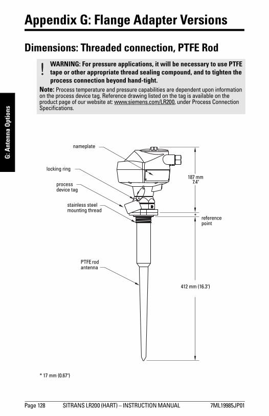
mm
mm
m
G: A
nten
na O
ptio
ns
Appendix G: Flange Adapter Versions
Dimensions: Threaded connection, PTFE Rod WARNING: For pressure applications, it will be necessary to use PTFE tape or other appropriate thread sealing compound, and to tighten the process connection beyond hand-tight.
Note: Process temperature and pressure capabilities are dependent upon information on the process device tag. Reference drawing listed on the tag is available on the product page of our website at: www.siemens.com/LR200, under Process Connection Specifications.
412 mm (16.3")
reference point
187 mm 7.4"
nameplate
locking ring
process device tag
stainless steel mounting thread
PTFE rod antenna
*
* 17 mm (0.67")
Page 128 SITRANS LR200 (HART) – INSTRUCTION MANUAL 7ML19985JP01
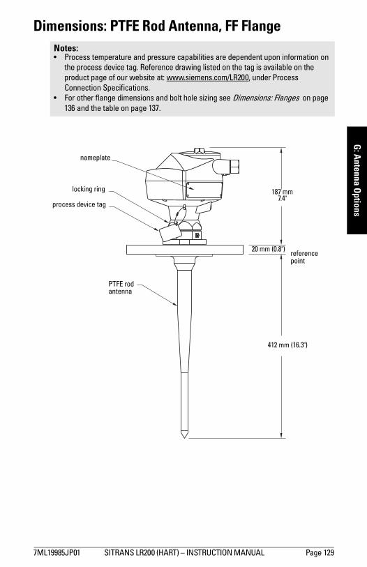
mm
mm
m
G: A
ntenna Options
Dimensions: PTFE Rod Antenna, FF Flange Notes: • Process temperature and pressure capabilities are dependent upon information on
the process device tag. Reference drawing listed on the tag is available on the product page of our website at: www.siemens.com/LR200, under Process Connection Specifications.
• For other flange dimensions and bolt hole sizing see Dimensions: Flanges on page 136 and the table on page 137.
PTFE rod antenna
reference point
nameplate
locking ring
process device tag
187 mm 7.4"
20 mm (0.8")
412 mm (16.3")
7ML19985JP01 SITRANS LR200 (HART) – INSTRUCTION MANUAL Page 129

mm
mm
m
G: A
nten
na O
ptio
ns
Dimensions: Threaded Connection, PTFE Rod, Shielded
WARNING: For pressure applications, it will be necessary to use PTFE tape or other appropriate thread sealing compound, and to tighten the process connection beyond hand-tight.
Note: Process temperature and pressure capabilities are dependent upon information on the process device tag. Reference drawing listed on the tag is available on the product page of our website at: www.siemens.com/LR200, under Process Connection Specifications.
stainless steel antenna shield (inactive length)
active antenna
Shield Length
SL
OverallLength
L
reference point
nameplate
locking ring
process device tag
187 mm 7.4"
*
stainless steel mounting thread
SL = min. 100 mm (4") (customer-specified)
L = 374 mm (14.7") plus shielded length
Page 130 SITRANS LR200 (HART) – INSTRUCTION MANUAL 7ML19985JP01

mm
mm
m
G: A
ntenna Options
Dimensions: FF Flange with Horn Antenna and Waveguide extension1)
1) A purging system is an option available for this antenna type. This provides an inlet on the flange where cooling air or cleaning fluid may be supplied. The air or liquid passes through the flange and exits the inside of the horn to clean the antenna sys-tem.
Notes: • For other flange dimensions and bolt hole sizing see Dimensions: Flanges on page
136 and the table on page 137.• See Horn dimensions on page 132 for more details.• Process temperature and pressure capabilities are dependent upon information on
the process device tag. Reference drawing listed on the tag is available on the product page of our website at: www.siemens.com/LR200, under Process Connection Specifications.
• Optional waveguide extensions and/or purging1) system can be installed between the flange and the antenna.
threaded cover
enclosure/electronics
187 mm (7.40")
154 mm (6.1")
185 mm (7.3")
1/2" NPT cable entry (or alternatively, M20 cable gland)
sensor referencepoint
131 mm (5.2")
100 mm (4.0") nom.
50 mm (2.0")
flange
80 mm (3.0") dia.
waveguide extensions 100 mm (4.00") to
300 mm (12.0")(optional)
hornantenna
process device tag
* 20 mm (0.80") (nominal)
*
325 mm (12.80")
226 mm (9.0")
150 mm (6.0") nom.
200 mm (8.0") nom.
7ML19985JP01 SITRANS LR200 (HART) – INSTRUCTION MANUAL Page 131

mm
mm
m
G: A
nten
na O
ptio
ns
Horn dimensions
Notes:• Signal amplitude increases with horn diameter, so use the largest practical size.• 80 mm ( 3") and 100 mm ( 4") are not recommended in vessels due to the wide beam/
poor performance. They are to be used in stillpipe applications only.
Nominal Horn Size Horn O.D. Horn Heighta)
a) Height from bottom of horn to sensor reference point
Beam Angleb)
b) – 3dB in the direction of the polarization axis (see Polarization reference point on page 16 for an illustration).
100 mm (4”) 95.3 mm (3.75”) 131.0 mm (5.16”) 29 degrees
150 mm (6”) 146.0 mm (5.75”) 225.8 mm (8.89”) 20 degrees
200 mm (8”) 199.4 mm (7.85”) 325.1 mm (12.79”) 17 degrees
Page 132 SITRANS LR200 (HART) – INSTRUCTION MANUAL 7ML19985JP01
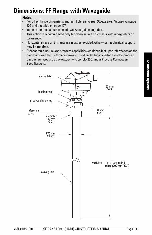
mm
mm
m
G: A
ntenna Options
Dimensions: FF Flange with WaveguideNotes:• For other flange dimensions and bolt hole sizing see Dimensions: Flanges on page
136 and the table on page 137.• You can connect a maximum of two waveguides together.• This option is recommended only for clean liquids on vessels without agitators or
turbulence. • Horizontal stress on this antenna must be avoided, otherwise mechanical support
may be required. • Process temperature and pressure capabilities are dependent upon information on the
process device tag. Reference drawing listed on the tag is available on the product page of our website at: www.siemens.com/LR200, under Process Connection Specifications.
nameplate
variable min: 100 mm (4")max: 3000 mm (123")
waveguide
57.2 mm(2.250”)
reference point
locking ring
process device tag
187 mm (7.4”)
40 mm (1.6”)
diameter 80 mm(3.0”)
7ML19985JP01 SITRANS LR200 (HART) – INSTRUCTION MANUAL Page 133

mm
mm
m
G: A
nten
na O
ptio
ns
Dimensions: Sliding Waveguide ConfigurationNotes:• Always clamp the instrument in the same position for operation.• For other flange dimensions and bolt hole sizing see Dimensions: Flanges on page
136 and the table on page 137.• Maximum pressure 0.5 bar at 60° C (140° F) for sliding flange option.• Process temperature and pressure capabilities are dependent upon information on the
process device tag. Reference drawing listed on the tag is available on the product page of our website at: www.siemens.com/LR200, under Process Connection Specifications.
sliding flange (See Flange Table on page 137.)
nameplate
1000 mm (40.8")
131.0 mm (5.16")
225.8 mm (8.89")
325.1 mm (12.8")150 mm
(6")
200 mm (8")
100 mm (4")
reference point
locking ring
process device tag
187 mm (7.4")
40 mm (1.6")
Page 134 SITRANS LR200 (HART) – INSTRUCTION MANUAL 7ML19985JP01
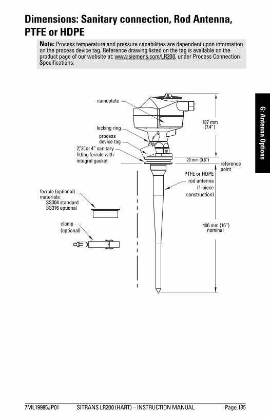
mm
mm
m
G: A
ntenna Options
Dimensions: Sanitary connection, Rod Antenna, PTFE or HDPE
Note: Process temperature and pressure capabilities are dependent upon information on the process device tag. Reference drawing listed on the tag is available on the product page of our website at: www.siemens.com/LR200, under Process Connection Specifications.
ferrule (optional)materials:
SS304 standardSS316 optional
2”, 3”, or 4” sanitary fitting ferrule with integral gasket
clamp(optional)
406 mm (16”) nominal
nameplate
reference point
locking ringprocess device tag
187 mm (7.4”)
20 mm (0.8”)
PTFE or HDPErod antenna
(1-piececonstruction)
7ML19985JP01 SITRANS LR200 (HART) – INSTRUCTION MANUAL Page 135

mm
mm
m
G: A
nten
na O
ptio
ns
Dimensions: Flanges
“A” “A”
process side
20 mm (0.8”), nominal
enclosure mounting holes(threaded)
bolt hole Ø
bolt hole circle Ø
flange O.D.
horn/waveguide mounting holes (threaded)
Page 136 SITRANS LR200 (HART) – INSTRUCTION MANUAL 7ML19985JP01

mm
mm
m
G: A
ntenna Options
Pipe size Flange Size Flange O.D. Bolt Hole Circle Ø Bolt Hole Ø Number
of Bolts
2” ANSI 150# 6.0” 4.75” .7” 4
3” ANSI 150# 7.5” 6.0” .75” 4
4” ANSI 150# 9.0” 7.50” .75” 8
6” ANSI 150# 11.0” 9.50” .88” 8
8” ANSI 150# 13.5” 11.75” .88” 8
2” ANSI 300#a) 6.50” 5.00” .75” 4a)
3” ANSI 300# 8.25” 6.62” .88” 8
4” ANSI 300# 10.00” 7.88” .88” 8
6” ANSI 300# 12.50” 10.62” .88” 12
8” ANSI 300# 15.00” 13.00” 1.00” 12
50 mm DIN PN 16 165 mm 125 mm 18 mm 4
80 mm DIN PN 16 200 mm 160 mm 18 mm 8
100 mm DIN PN 16 220 mm 180 mm 18 mm 8
150 mm DIN PN 16 285 mm 240 mm 22 mm 8
200 mm DIN PN 16 340 mm 295 mm 22 mm 12
200 mm DIN PN 25 360 mm 310 mm 26 mm 12
50 mm DIN PN 40 165 mm 125 mm 18 mm 4
80 mm DIN PN 40 200 mm 160 mm 18 mm 8
100 mm DIN PN 40 235 mm 190 mm 22 mm 8
150 mm DIN PN 40 300 mm 250 mm 26 mm 8
200 mm DIN PN 40 375 mm 320 mm 30 mm 12
50 mm JIS 10K 155 mm 120 mm 19 mm 4
80 mm JIS 10K 185 mm 150 mm 19 mm 8
100 mm JIS 10K 210 mm 175 mm 19 mm 8
150 mm JIS 10K 280 mm 240 mm 23 mm 8
200 mm JIS 10K 330 mm 290 mm 23 mm 12
a) Due to the limited space on this flange, SITRANS LR200 can only use 4 of the stan-dard 8 bolt holes of the 2” ANSI #300 size.
7ML19985JP01 SITRANS LR200 (HART) – INSTRUCTION MANUAL Page 137

mm
mm
m
G: A
nten
na O
ptio
ns
Flange markingThe flange markings are located around the outside edge of the flange.
Serial number: a unique number allotted to each flange, including the date of manufacture (mmddyy) followed by a number from 001 to 999.
Flange series: the SMPI drawing identification.
Nominal size: a combination of the nominal pipe size and the hole pattern for a particular flange class. In the examples above, a 2 inch (or 80 mm) nominal pipe size is combined with the hole pattern corresponding to an ASME 150 lb class flange (or EN 1092-1 PN 16 class flange).
Material: the basic flange material (AISI or EU material designation).
Heat code: a flange material batch code identification.
Threaded Connection MarkingsThreaded connection markings are found on the flat face/faces of the process connection.
Serial number:a unique number allotted to each flange, including the date of manufacture (MMDDYY) followed by a number from 001 to 999.
Serial No. Logo
Flange Series Nominal Size Material
Heat Code
North American
MMDDYYXXX
22452 2 150 316/316L A1B2C3
European MMDDYYXXX
22452 DN 80 PN 16 1.4571 A1B2C3
Logo Serial Number Thread Size Thread Series
MMDDYYXXX1.5
NPT
BSP
G/PF
Page 138 SITRANS LR200 (HART) – INSTRUCTION MANUAL 7ML19985JP01

mm
mm
m
G: A
ntenna Options
Flange Mounting Instructions
1)
* Refer to the Rod Extension Requirements table on page 140.
Notes:• The integral process seal MUST rest on the customer-supplied flange (see the
detail below). • The straight/taper transition of the rod should extend past the nozzle/vessel
opening. Add extensions as required1).
1) Refer to the Rod Extension Requirements table on page 140
1/2" NPT or M20 x 1.5cable entry
straight/taper transition
nozzle/vessel juncture
integral process seal
customer-supplied flange
customer-flanged nozzle to suit
wiring access cover
minimum diameter 2" / DIN 50
vessel
locking ringprocess device tag
7ML19985JP01 SITRANS LR200 (HART) – INSTRUCTION MANUAL Page 139

mm
mm
m
G: A
nten
na O
ptio
ns
Rod Assembly
Rod Extension Requirements
WARNING: For pressure applications, it will be necessary to use PTFE tape or other appropriate thread sealing compound, and to tighten the process connection beyond hand-tight.
Nozzle I.D. Nozzle Heighta) mm (inches)
a) Consult Siemens Milltronics for assistance with nozzle sizes not listed.
<100 (4) 100 to 150 (4 to 6) 150 to 200 (6 to 8)50 mm (2”)
extension not required
Application not recommended for 50 mm (2”) I.D. nozzles
longer than 100 mm (4”)b).
b) Shielded rod antennas are available for these applications.
80 mm (3”) 50 mm 100 mm
100 mm (4”) 50 mm 100 mm
150 mm (6”) 50 mm 100 mm
>150 mm (6”) extension not required
50 mm(2”)
PTFE paste is supplied with PTFE rod antenna versions (non-sanitary type)
OptionalExtension 100 mm
(4")
Notes:• Water or process fluids must not
enter the connecting threads: this could cause reflections at the connection, which will appear as false echoes.
• Apply a small amount of PTFE paste to the antenna threads before threading the antenna together, and tighten slowly. Ensure that the rod sections mate securely with no gaps. Do not apply too much PTFE paste or the parts will not mate securely.
• Do not use wrenches or pliers. Hand tighten only (except in pressure applications: see warning above).
Page 140 SITRANS LR200 (HART) – INSTRUCTION MANUAL 7ML19985JP01

mm
mm
m
G: A
ntenna Options
Mounting Guidelines
Nozzle fabricationWeld seams must be on the outside of the nozzle. Seams or lips on the inside of the nozzle may cause erratic readings.
Nozzle design• The nozzle should be as short as possible. • If your application requires a nozzle longer than our
recommended maximum length consider using a shielded rod.
Horn AntennasThe end of the horn should protrude a minimum of 10 mm (0.4”) to avoid interference from the nozzle.
Threaded Rod Antenna
1.5” or 2” threaded process connections are available in three thread types: NPT, BSP, and G.
Sanitary Rod Antenna2”, 3”, and 4” sanitary fitting ferrule with integral gasket, with rod antenna
WARNING: For pressure applications, it is necessary to use PTFE tape or other appropriate thread sealing compound, and to tighten the process connection beyond hand-tight.
Max. nozzle height: 100 mm (4")
10 mm (0.4")
min. I.D. 100 mm (4")
For smaller diameters use a shielded rod
316 S.S.
PTFE
Max. nozzle height 100 mm (4")
sanitary fitting ferrule
7ML19985JP01 SITRANS LR200 (HART) – INSTRUCTION MANUAL Page 141

mm
mm
m
G: A
nten
na O
ptio
ns
Waveguide Antenna
• Recommended for products with a dK lower than 3.• See Propagation Factor (2.2.1.14.) on page 54 for the
related propagation factor.
Horn with Waveguide Extensions• Recommended for long nozzles with a
small diameter.
For example, if the nozzle is 100 mm (4”) in diameter and 460 mm (18”) in length), the rod antenna is not suitable due to interference from the nozzle.
• Waveguide extensions are available in custom lengths.
• The horn must be connected to the SITRANS LR200 process flange.
Notes: • You can connect a maximum of two waveguides
together.• This option is recommended only for clean liquids,
and only on vessels without an agitator, with no turbulence.
• Horizontal stress on this antenna must be avoided, otherwise mechanical support may be required.
• Process temperature and pressure capabilities are dependent upon information on the process device tag. The reference drawing listed on the tag can be downloaded from our website at: www.siemens.com/LR200.
vent hole
minimum 80 mm (3")
If horn diameter is too large for the nozzle opening, insert it from inside the vessel.
Page 142 SITRANS LR200 (HART) – INSTRUCTION MANUAL 7ML19985JP01

mm
mm
m
G: A
ntenna Options
Mounting on a Stillpipe or Bypass Pipe• Used for products with a dK less than 3.• Used when vortex or extremely turbulent conditions exist.• Provides optimum signal conditions on foaming materials.• A horn antenna is preferred, but a rod antenna may also be used.
Stillpipe or Bypass Pipe requirements
• One continuous length of metallic pipe is preferred, without joints1). If joints are unavoidable they must be machined to ± 0.25 mm (± 0.010”) and must
have a welded connecting sleeve on the outside.• Suitable pipe diameters: 50 mm (2”) to 250 mm (10”).
• Bypass vent: required at the upper end of the bypass2) • Propagation factor. depends on pipe diameter. See Propagation Factor
(2.2.1.14.) on page 54 for a table.
Device orientation
1) Bad joints create reflections.2) To equalize pressure and keep the liquid level in the bypass constant with the liquid
level in the vessel.
align front or back of device with vents
Bypass Installation Stillpipe Installation
align front or back of device with stillpipe slots
optimum diameter80 mm (3”)
vent
slots
7ML19985JP01 SITRANS LR200 (HART) – INSTRUCTION MANUAL Page 143

mm
mm
m
H: A
TEX
Cert
ifica
tes
Appendix H: ATEX Certificates
Flameproof/Increased Safety: ATEX Certificate
Note: ATEX certificates can be downloaded from the product page of our website at: www.siemens.com/LR200.
Page 144 SITRANS LR200 (HART) – INSTRUCTION MANUAL 7ML19985JP01

mm
mm
m
H: ATEX Certificates
Flameproof/Increased Safety: ATEX Certificate (continued)
7ML19985JP01 SITRANS LR200 (HART) – INSTRUCTION MANUAL Page 145

mm
mm
m
H: A
TEX
Cert
ifica
tes
Flameproof/Increased Safety: ATEX Certificate (continued)
Page 146 SITRANS LR200 (HART) – INSTRUCTION MANUAL 7ML19985JP01

mm
mm
m
H: ATEX Certificates
Flameproof/Increased Safety: ATEX Certificate (continued)
7ML19985JP01 SITRANS LR200 (HART) – INSTRUCTION MANUAL Page 147
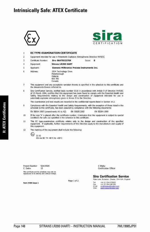
mm
mm
m
H: A
TEX
Cert
ifica
tes
Intrinsically Safe: ATEX Certificate
Page 148 SITRANS LR200 (HART) – INSTRUCTION MANUAL 7ML19985JP01

mm
mm
m
H: ATEX Certificates
Intrinsically Safe: ATEX Certificate (continued)
7ML19985JP01 SITRANS LR200 (HART) – INSTRUCTION MANUAL Page 149
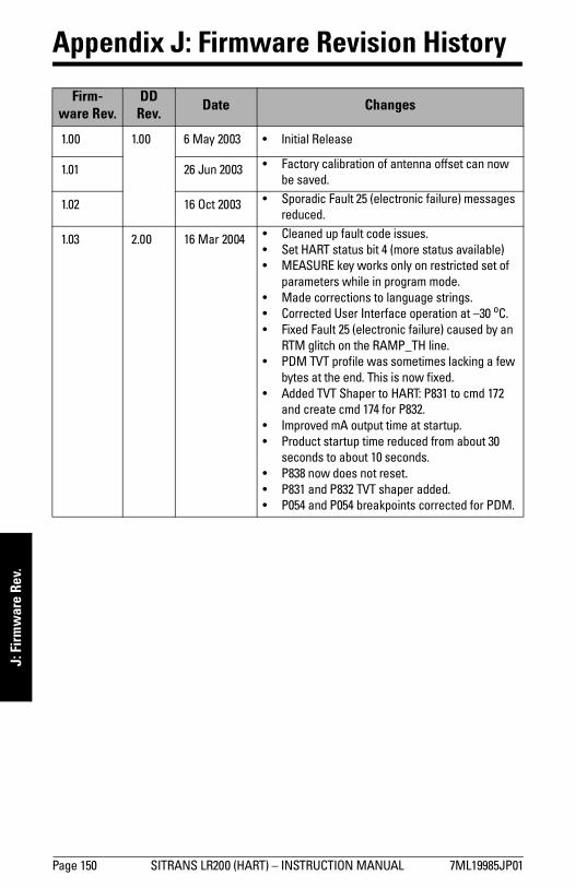
mm
mm
m
J: F
irmw
are
Rev.
Appendix J: Firmware Revision History
Firm-ware Rev.
DD Rev. Date Changes
1.00 1.00 6 May 2003 • Initial Release
1.01 26 Jun 2003 • Factory calibration of antenna offset can now be saved.
1.02 16 Oct 2003 • Sporadic Fault 25 (electronic failure) messages reduced.
1.03 2.00 16 Mar 2004 • Cleaned up fault code issues.• Set HART status bit 4 (more status available)• MEASURE key works only on restricted set of
parameters while in program mode.• Made corrections to language strings.• Corrected User Interface operation at –30 oC.• Fixed Fault 25 (electronic failure) caused by an
RTM glitch on the RAMP_TH line.• PDM TVT profile was sometimes lacking a few
bytes at the end. This is now fixed.• Added TVT Shaper to HART: P831 to cmd 172
and create cmd 174 for P832.• Improved mA output time at startup.• Product startup time reduced from about 30
seconds to about 10 seconds.• P838 now does not reset. • P831 and P832 TVT shaper added.• P054 and P054 breakpoints corrected for PDM.
Page 150 SITRANS LR200 (HART) – INSTRUCTION MANUAL 7ML19985JP01
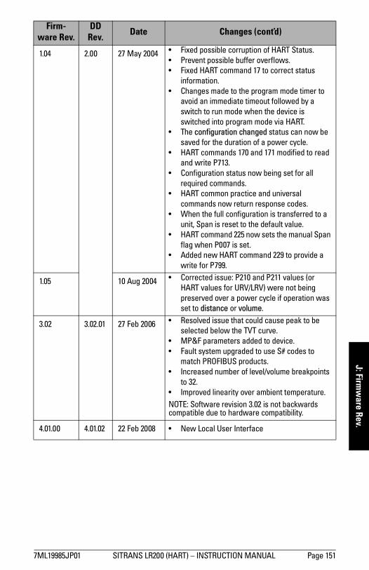
mm
mm
m
J: Firmw
are Rev.
1.04 2.00 27 May 2004 • Fixed possible corruption of HART Status.• Prevent possible buffer overflows.• Fixed HART command 17 to correct status
information.• Changes made to the program mode timer to
avoid an immediate timeout followed by a switch to run mode when the device is switched into program mode via HART.
• The configuration changed status can now be saved for the duration of a power cycle.
• HART commands 170 and 171 modified to read and write P713.
• Configuration status now being set for all required commands.
• HART common practice and universal commands now return response codes.
• When the full configuration is transferred to a unit, Span is reset to the default value.
• HART command 225 now sets the manual Span flag when P007 is set.
• Added new HART command 229 to provide a write for P799.
1.05 10 Aug 2004 • Corrected issue: P210 and P211 values (or HART values for URV/LRV) were not being preserved over a power cycle if operation was set to distance or volume.
3.02 3.02.01 27 Feb 2006 • Resolved issue that could cause peak to be selected below the TVT curve.
• MP&F parameters added to device.• Fault system upgraded to use S# codes to
match PROFIBUS products.• Increased number of level/volume breakpoints
to 32.• Improved linearity over ambient temperature.NOTE: Software revision 3.02 is not backwards compatible due to hardware compatibility.
4.01.00 4.01.02 22 Feb 2008 • New Local User Interface
Firm-ware Rev.
DD Rev. Date Changes (cont’d)
7ML19985JP01 SITRANS LR200 (HART) – INSTRUCTION MANUAL Page 151

mm
mm
m
J: F
irmw
are
Rev.
Notes
Page 152 SITRANS LR200 (HART) – INSTRUCTION MANUAL 7ML19985JP01

mm
mm
m
Glossary
Glossary
accuracy: degree of conformity of a measure to a standard or a true value.
agitator: mechanical apparatus for mixing or aerating. A device for creating turbulence.
algorithm: a prescribed set of well-defined rules or processes for the solution of a problem in a finite number of steps.
ambient temperature: the temperature of the surrounding air that comes in contact with the enclosure of the device.
antenna: an aerial which sends out and receives a signal in a specific direction. There are four basic types of antenna in radar level measurement, horn, parabolic, rod, and waveguide.
attenuation: a term used to denote a decrease in signal magnitude in transmission from one point to another. Attenuation may be expressed as a scalar ratio of the input magnitude to the output magnitude or in decibels.
Auto False-Echo Suppression: a technique used to adjust the level of a TVT curve to avoid the reading of false echoes. (See TVT.)
Auto False-Echo Suppression Distance: defines the endpoint of the TVT distance. (See TVT.) This is used in conjunction with auto false echo suppression.
beam angle: the angle diametrically subtended by the one-half power limits (-3 dB) of the sound beam.
beam spreading: the divergence of a beam as it travels through a medium.
blanking: a blind zone extending away from the reference point plus any additional shield length.The instrument is programmed to ignore this zone.
capacitance: the property of a system of conductors and dielectrics that permits the storage of electricity when potential differences exist between the conductors. Its value is expressed as the ratio of a quantity of electricity to a potential difference, and the unit is a Farad.
confidence: see Echo Confidence
damping: term applied to the performance of an instrument to denote the manner in which the measurement settles to its steady indication after a change in the value of the level.
dB (decibel): a unit used to measure the amplitude of signals.
derating: to decrease a rating suitable for normal conditions according to guidelines specified for different conditions.
dielectric: a nonconductor of direct electric current.1)
1) Many conductive liquids/electrolytes exhibit dielectric properties; the relative dielec-tric constant of water is 80.
7ML19985JP01 SITRANS LR200 (HART) – INSTRUCTION MANUAL Page 153

mm
mm
m
Glo
ssar
y
dielectric constant (DK): the ability of a dielectric to store electrical potential energy under theinfluence of an electric field. Also known as Relative Permittivity. An increase in the dielectric constant is directly proportional to an increase in signal amplitude. The value is usually given relative to a vacuum /dry air: the dielectric constant of air is 11.
echo: a signal that has been reflected with sufficient magnitude and delay to be perceived in some manner as a signal distinct from that directly transmitted. Echoes are frequently measured in decibels relative to the directly transmitted signal.
Echo Confidence: describes the quality of an echo. Higher values represent higher quality. Echo Threshold defines the minimum value required for an echo to be accepted as valid and evaluated.
Echo Lock Window: a window centered on an echo in order to locate and display the echo’s position and true reading. Echoes outside the window are not immediately processed.
Echo Marker: a marker that points to the processed echo.
Echo Processing: the process by which the radar unit determines echoes.
Echo Profile: a graphical display of a processed echo.
Echo Strength: describes the strength of the selected echo in dB referred to 1 µV rms.
Echo Threshold: see Echo Confidence
false echo: any echo which is not the echo from the desired target. Generally, false echoes are created by vessel obstructions.
frequency: the number of periods occurring per unit time. Frequency may be stated in cycles per second.
hertz (Hz): unit of frequency, one cycle per second. 1 Gigahertz (GHz) is equal to 109 Hz.
HART: Highway Addressable Remote Transducer. An open communication protocol used to address field instruments.
horn antenna: a conical, horn-shaped antenna which focuses microwave signals. The larger the horn diameter, the more focused the radar beam.
inductance: the property of an electric circuit by virtue of which a varying current induces an electromotive force in that circuit or in a neighboring circuit. The unit is a Henry.
microwaves: the term for the electromagnetic frequencies occupying the portion of the radio frequency spectrum from 1 GHz to 300 GHz.
multiple echoes: secondary echoes that appear as double, triple, or quadruple echoes in the distance from the target echo.
Near Blanking: see Blanking
nozzle: a length of pipe mounted onto a vessel that supports the flange.
parameters: in programming, variables that are given constant values for specific purposes or processes.
Page 154 SITRANS LR200 (HART) – INSTRUCTION MANUAL 7ML19985JP01

mm
mm
m
Glossary
polarization: the property of a radiated electromagnetic wave describing the time-varying direction and amplitude of the electric field vector.
polarization error: the error arising from the transmission or reception of an electromagnetic wave having a polarization other than that intended for the system.
propagation factor (pf): where the maximum velocity is 1.0, pf is a value that represents a reduction in propagation velocity as a result of the wave travelling through a pipe or medium.
pulse radar: a radar type that directly measures distance using short microwave pulses. Distance is determined by the return transmit time.
radar: radar is an acronym for RAdio Detection And Ranging. A device that radiates electromagnetic waves and utilizes the reflection of such waves from distant objects to determine their existence or position.
range: distance between a transmitter and a target.
range extension: the distance below the zero percent or empty point in a vessel.
relative humidity: the ratio of the actual amount of moisture in the atmosphere to the maximum amount of moisture the atmosphere could hold (which varies depending on the air temperature).
relative permittivity: see dielectric constant.
repeatability: the closeness of agreement among repeated measurements of the same variable under the same conditions.
shield: the area of the rod which is inactive. The shield length must be longer than the vessel nozzle height.
shot: one transmit pulse or measurement.
speed of light: the speed of electromagnetic waves (including microwave and light) in free space. Light speed is a constant 299, 792, 458 meters per second.
stillpipe: a pipe that is mounted inside a vessel parallel to the vessel wall, and is open to the vessel at the bottom.
stilling-well: see stillpipe.
two wire radar: a low-energy radar. Can be loop powered, analog, intrinsically safe 4 to 20 mA, or a digital (BUS) transmitter.
TVT (time varying threshold): a time-varying curve that determines the threshold level above which echoes are determined to be valid.
waveguide antenna: a hollow, metallic tube that transmits a microwave signal to the product target.
7ML19985JP01 SITRANS LR200 (HART) – INSTRUCTION MANUAL Page 155

mm
mm
m
Glo
ssar
y
Notes
Page 156 SITRANS LR200 (HART) – INSTRUCTION MANUAL 7ML19985JP01

mm
mm
m
Index
Index
Aabbreviations
meanings 4activating LR200 24address
reset via handheld programmer 33agitator blade detection
avoiding 61analog output
in Measure mode 108antenna
replacement 104application example
level setup via LUI 33Auto False Echo Suppression
explanation 107setup 63setup via PDM 44TVT shaper adjustment 45
Bbeam angle
values 132beam angle spread 15blanking (see Near Range) 108burst mode 127bypass pipe
installation 143Ccables
requirements 17Calibration Interval
setup 86cleaning
instructions 104CLEF range 62Communication Control
enable remote operation 89conduits
requirements 17configuration
new device via PDM 35DD/A Trim
via PDM 48
damping filter 62Device Address
reset via handheld programmer 33reset via PDM 89
Device Description (DD)HART 124
Device Statusaccess via PDM 49diagnostic status 49extended diagnostics 49maintenance 49see Diagnostics 73
device statusicons 96
Diagnostics 73dimensions
flange-mounted rod antenna 129flanges 136horn 133horn antenna 133PTFE threaded rod antenna 128sanitary rod antenna 135shielded PTFE rod antenna 130sliding waveguide 134threaded horn with extension 131Uni-construction Polypropylene Rod
Antenna 12waveguide 133
displayview online via PDM 46
Eecho profile viewing
via LUI 32via PDM 46
edit modehandheld programmer 28
emission coneillustration 15
enclosureopening 17
error messagessee general fault codes 97
Ffactory defaults
device reset via LUI 81device reset via PDM 48
7ML19985JP01 SITRANS LR200 (HART) – INSTRUCTION MANUAL Page 157

mm
mm
m
Inde
x
Fail-safesettings 72Fail-safe Mode
explanation 110Fail-safe Timer
explanation 110Fail-safe value
explanation 110Far Range
explanation 108fault codes
general fault codes 97Fault Reset 73flange marking 138flange sizes
chart 137function keys
Edit mode 29measurement mode 26navigation mode 28
Ggeneral fault codes 97Hhandheld programmer
edit mode 28function keys, measurement mode 26navigation 28
HARTDevice Description (DD) 124multidrop mode 127typical PLC/mA configuration 18
HART Communicationsdetails 124
HART version 127hazardous area installations
wiring requirements 19Iicons
device status 96identifications and abbreviations
meanings 4installation
device orientation 16enclosure rotating 16hazardous area requirements 19on a vessel with obstructions 16requirements 13temperature guidelines 15vessel shape notes 14
Llanguage 91LCD display
Contrast 82echo profile viewing 32Fast Mode 81fault code/error message 24Measurement mode 24PROGRAM mode 25
level trendview via PDM 47
lid-lock set screw 17local operation enable 90lock parameter
enable/disable local operation 90locking ring 16
set-screw size 17loop voltage
versus loop resistance 116Loss of Echo (LOE)
explanation 110LUI
local user interface 24MmA output in Measure mode 108mA output settings 69maintenance
cleaning 104parameter settings via PDM 47
maintenance settingssee Diagnostics 73
Measurement Responseexplanation 108
Memory Test 82mounting
bypass requirements 143flange mounting instructions 139flange-mounted options 141handheld programmer access 14manhole cover 14nozzle design 14nozzle location 14stillpipe requirements 143sunshield recommended 15
multidrop mode 127NNear Range
explanation 108
Page 158 SITRANS LR200 (HART) – INSTRUCTION MANUAL 7ML19985JP01

mm
mm
m
Index
Ooperating principles 105Pparameter settings
adjust via LUI 28adjusting via PDM 43
PDMsee SIMATIC PDM 34
pipe sizesflange mounting 137
polarization reference point 16power
requirements 7power source
input terminal requirements 17insulation requirements 17
process temperaturemaximum 111
programmingvia LUI 26via PDM 43
QQuick Access
to parameters via LUI 28Quick Start (PDM)
launching 36Quick Start Wizard
via LUI 30via SIMATIC PDM 36
Rrange extension
see Far Range 108remote operation enable 89repair
antenna replacement 104excluded liability 104
resetfactory defaults via LUI 81factory defaults via PDM 48
rod assembly 140rod extension requirements 140Ssafety notes 1sensor reference point
threaded horn 131sensor value
illustration 52Service Interval
setup 83
service required icon 24set address
via handheld programmer 33settings
adjust parameters via LUI 28adjust parameters via PDM 43Fail-safe 72mA output 69Quick Access via LUI 28
sidepipesee bypass pipe 143
SIMATIC PDMconfiguring new device 35overview 34Quick Start 36Rev. 5.2, SP1 features 34Rev. 6.0 SP3 features 34
simulate analog outputvia PDM 49
SITRANS LR200overview 5
startup curve 117stillpipe
installation 143stillpipe application
configuring via PDM 42support
contact information 3Ttechnical support
contact information 3temperature de-Rating
curves 112terminal access 17threaded connection markings 138trend
view level trend via PDM 47troubleshooting
communications 95operation 102
TVT curve 107TVT setup 63TVT Shaper
manual adjustment via PDM 45Uunlock value 90Vvessel shape
installation notes 14selection 55
7ML19985JP01 SITRANS LR200 (HART) – INSTRUCTION MANUAL Page 159

mm
mm
m
Inde
x
volume breakpointssetup 57Wwear
view via PDM 49wiring
cables 17conduit seals 17connecting HART 18hazardous area installations 19terminal access 17
Page 160 SITRANS LR200 (HART) – INSTRUCTION MANUAL 7ML19985JP01
SITRAN RANS LR200 (HART) – INSTRUCTION MANUAL 7ML19985JP01
App
endi
x C:
men
u ch
art
S LR200 (HART) – INSTRUCTION MANUAL Page 161 SIT
LCD menu structure
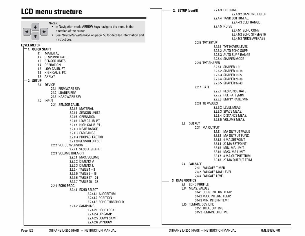
Page 162 SIT 200 (HART) – INSTRUCTION MANUAL 7ML19985JP01
App
endi
x C:
men
u ch
art LCD menu structure
LEVEL METER1. QUICK START
1.1 MATE1.2 RESPO1.3 SENS1.4 OPER1.5 LOW C1.6 HIGH 1.7 APPLY
2. SETUP2.1 DEVIC
222
2.2 INPUT2
2
2
2
2.2.4.3 FILTERING2.2.4.3.2 DAMPING FILTER
2.2.4.4 TANK BOTTOM AL.2.2.4.4.3 CLEF RANGE
2.2.4.5 NOISE2.2.4.5.1 ECHO CONF.2.2.4.5.2 ECHO STRENGTH2.2.4.5.3 NOISE AVERAGE
2.2.5 TVT SETUP2.2.5.1 TVT HOVER LEVEL2.2.5.2 AUTO ECHO SUPP2.2.5.3 AUTO SUPP RANGE2.2.5.4 SHAPER MODE
2.2.6 TVT SHAPER2.2.6.1 SHAPER 1-92.2.6.2 SHAPER 10-182.2.6.3 SHAPER 19-272.2.6.4 SHAPER 28-362.2.6.5 SHAPER 37-40
2.2.7 RATE2.2.7.1 RESPONSE RATE2.2.7.2 FILL RATE /MIN2.2.7.3 EMPTY RATE /MIN
2.2.8 TB VALUES2.2.8.2 LEVEL MEAS.2.2.8.3 SPACE MEAS.2.2.8.4 DISTANCE MEAS.2.2.8.5 VOLUME MEAS.
3 OUTPUT2.3.1 MA OUTPUT
2.3.1.1 MA OUTPUT VALUE2.3.1.2 MA OUTPUT FUNC.2.3.1.3 4 MA SETPOINT2.3.1.4 20 MA SETPOINT2.3.1.5 MIN. MA LIMIT2.3.1.6 MAX. MA LIMIT2.3.1.7 4 MA OUTPUT TRIM2.3.1.8 20 MA OUTPUT TRIM
4 FAIL-SAFE2.4.1 FAILSAFE TIMER2.4.2 FAILSAFE MAT. LEVEL2.4.4 FAILSAFE LEVEL
OSTICSECHO PROFILE
4 MEAS. VALUES3.14.1 CURR. INTERN. TEMP.3.14.2 MAX. INTERN. TEMP.3.14.3 MIN. INTERN TEMP.
5 REMAIN. DEV. LIFE3.15.1 TOTAL OP-TIME3.15.2 REMAIN. LIFETIME
Notes: • In Navigation mode ARROW keys navigate the menu in the
direction of the arrow.. • See Parameter Reference on page 50 for detailed information and
2. SETUP (cont’d)
RANS LR200 (HART) – INSTRUCTION MANUAL SITRANS LR
RIALNSE RATE
OR UNITSATION
ALIB. PT.CALIB. PT.?
E.1.1 FIRMWARE REV.1.2 LOADER REV.1.3 HARDWARE REV
.2.1 SENSOR CALIB.2.2.1.2 MATERIAL2.2.1.4 SENSOR UNITS2.2.1.5 OPERATION2.2.1.6 LOW CALIB. PT.2.2.1.7 HIGH CALIB. PT.2.2.1.11 NEAR RANGE2.2.1.12 FAR RANGE2.2.1.14 PROPAG. FACTOR2.2.1.20 SENSOR OFFSET
.2.2 VOL CONVERSION2.2.2.1 VESSEL SHAPE
.2.3 VOLUME BREAKPT2.2.3.1 MAX. VOLUME2.2.3.2 DIMENS. A2.2.3.3 DIMENS. L2.2.3.4 TABLE 1 – 82.2.3.5 TABLE 9 – 162.2.3.6 TABLE 17 – 242.2.3.7 TABLE 25 – 32
.2.4 ECHO PROC.2.2.4.1 ECHO SELECT
2.2.4.1.1 ALGORITHM2.2.4.1.2 POSITION2.2.4.1.3 ECHO THRESHOLD
2.2.4.2 SAMPLING2.2.4.2.1 ECHO LOCK2.2.4.2.4 UP SAMP. 2.2.4.2.5 DOWN SAMP. 2.2.4.2.6 WINDOW
2.
2.
3. DIAGN3.13.1
3.1
instructions.

mm
mm
m
LCD menus
3.15.3 MAINT REQ LIMIT3.15.4 MAINT DEM LIMIT3.15.5 ALERT ACTIVATIO.3.15.6 TOTAL EXP. LIFE3.15.7 MAINT STAT3.15.8 ACK STATUS3.15.9 ACK
3.16 REMAIN. SENS. LIFE3.16.1 SENS OP--TIME3.16.2 REMAIN. LIFETIME3.16.3 MAINT REQ LIMIT3.16.4 MAINT DEM LIMIT3.16.5 ALERT ACTIVATION3.16.6 TOTAL EXP. LIFE3.16.7 MAINT STAT3.16.8 ACK STATUS3.16.9 ACK
4. SERVICE4.1 DEVICE RESET4.2 MANUF. DATE4.3 LCD FAST MODE4.4 LCD CONTRAST4.6 POWERED HOURS4.8 POWERON RESETS4.11 MEM. TEST4.16 SERVICE INTERVA.
4.16.1 TIME LAST SERV4.16.2 REMAIN LIFETIME4.16.3 MAINT REQ LIMIT4.16.4 MAINT DEM LIMIT4.16.5 ALERT ACTIVATIO.4.16.6 SERVICE INTERVA.4.16.7 MAINT STAT4.16.8 ACK STATUS4.16.9 ACK
4.17 CALIB. INTERVAL4.17.1 TIME LAST CAL.4.17.2 REMAIN LIFETIME4.17.3 MAINT REQ LIMIT4.17.4 MAINT DEM LIMIT4.17.5 ALERT ACTIVATIO.4.17.6 TOTAL CALIB.INT..4.17.7 MAINT STAT4.17.8 ACK STATUS4.17.9 ACK
5. COMMUNICATION5.1 DEVICE ADDRESS5.2 COMM. CONTROL
6. SECURITY6.1 LOCK6.2 UNLOCK VALUE
7. LANGUAGE
3. DIAGNOSTICS (cont’d)
7ML19985JP01 SITRANS LR200 (HART) – INSTRUCTION MANUAL Page 163

mm
mm
m
LCD
men
us
Notes
Page 164 SITRANS LR200 (HART) – INSTRUCTION MANUAL 7ML19985JP01

*7ml19985JP01*Rev. 1.0
www.siemens.com/processautomation
Siemens Milltronics Process Instruments Inc.1954 Technology Drive, P.O. Box 4225Peterborough, ON, Canada K9J 7B1Tel: (705) 745-2431 Fax: (705) 741-0466Email: [email protected]
Siemens Milltronics Process Instruments Inc. 2008Subject to change without prior notice
Printed in Canada


