Family of Curves for Dosamatic A-21 Proportioner Percent Foam Blend versus Flowrate
Silvex
.5%, 85 psi
.7%, 85psi
0.00
0.20
0.40
0.60
0.80
1.00
1.20
1.40
1.60
1.80
0 25 50 75 100
125
150
175
200
225
250
275
300
Per
cent
Foa
m B
lend
Flowrate--GPM
Foam Blend Comparison Curves for 0.7% Foam Blend, 300 psi
Robwen 500
Foam Pro 1601
Foam Pro 2001
0.7% Foam Blend plus 30%0.7% Foam Blend minus 30%
FOAM PROPERTIONERTEST UNIT
FOAM CONCENTRATE
P1 P2
FLOWMETER
3" FLOWCONTROL VALVE
WATER SUPPLY
SCALE TO WEIGH FOAM CONCENTRATE
FLOW FLOW
Foam Proportioner Performance EvaluationbyWilliam V. CraneCivil Engineer (Retired)
USDA Forest ServiceSan Dimas Technology & Development CenterSan Dimas, California
August 2011
The information contained in this publication has been developed for the guidance of employees of the Forest Service, U.S. Department of Agriculture, its contractors, and cooperating Federal and State agencies. The Forest Service assumes no responsibility for the interpretation or use of this information by other than its own employees. The use of trade, firm, or corporation names is for the information and convenience of the reader. Such use does not constitute an official evaluation, conclusion, recommendation, endorsement, or approval of any product or service to the exclusion of others that may be suitable.
The U.S. Department of Agriculture (USDA) prohibits discrimination in all its programs and activities on the basis of race, color, national origin, age, disability, and where applicable, sex, marital status, familial status, parental status, religion, sexual orientation, genetic information, political beliefs, reprisal, or because all or part of an individual’s income is derived from any public assistance program. (Not all prohibited bases apply to all programs.) Persons with disabilities who require alternative means for communication of program information (Braille, large print, audiotape, etc.) should contact USDA’s TARGET Center at (202) 720-2600 (voice and TDD). To file a complaint of discrimination, write USDA, Director, Office of Civil Rights, 1400 Independence Avenue, S.W., Washington, D.C. 20250-9410, or call (800) 795-3272 (voice) or (202) 720-6382 (TDD). USDA is an equal opportunity provider and employer.
-20.00
0.00
20.00
40.00
60.00
80.00
100.00
120.00
140.00
0 20 40 60 80 100
120
140
160
Pre
ssur
e Lo
ss--
psi
Flowrate--gpm
Family of Curves for Robwen Hydroflow 100 Proportioner Pressure Loss versus Flowrate
Silvex
.3%, 100psi
.5%, 50psi
.5%, 100psi
.5%, 300 psi
.7%, 100psi
0.00
5.00
10.00
15.00
20.00
25.00
30.00
35.00
40.00
0 25 50 75 100
125
150
175
200
225
250
275
300
Pre
ssur
e Lo
ss--
psi
Flowrate--GPM
Pressure Loss Comparison Curves for0.3% Foam Blend, 300 psi
Family of Curves for Dosamatic A-21 Proportioner Percent Foam Blend versus Flowrate
Silvex
.5%, 85 psi
.7%, 85psi
0.00
0.20
0.40
0.60
0.80
1.00
1.20
1.40
1.60
1.80
0 25 50 75 100
125
150
175
200
225
250
275
300
Per
cent
Foa
m B
lend
Flowrate--GPM
Foam Blend Comparison Curves for 0.7% Foam Blend, 300 psi
Robwen 500
Foam Pro 1601
Foam Pro 2001
0.7% Foam Blend plus 30%0.7% Foam Blend minus 30%
FOAM PROPERTIONERTEST UNIT
FOAM CONCENTRATE
P1 P2
FLOWMETER
3" FLOWCONTROL VALVE
WATER SUPPLY
SCALE TO WEIGH FOAM CONCENTRATE
FLOW FLOW
Table of Contents
Introduction .......................................................................................................................................................1Automatic Regulating Proportioning Systems ..................................................................................................2 Direct Injection...........................................................................................................................................2 Venturi System ..........................................................................................................................................2
Testing and Evaluation Methods......................................................................................................................4Discussion ........................................................................................................................................................4 High Viscosity Foam Concentrates ...........................................................................................................4 Effects of Temperatures ............................................................................................................................5 Proportioner Accuracy and Economics .....................................................................................................5
Proportioner Test Results and Performance Curves ........................................................................................6 Darley Fast Foam 50 .................................................................................................................................6 Robwen Hydroflow 100 .............................................................................................................................7 Hale V Series 1.01V ..................................................................................................................................9 Foam Pro 1600........................................................................................................................................10 Foam Pro 1601........................................................................................................................................12 Foam Pro 2001........................................................................................................................................13 Haler Foam Logix 2.1A ............................................................................................................................14 Robwen 500P ..........................................................................................................................................15
Conclusions and Recomendations .................................................................................................................17
Considerations for Choosing a Foam Proportioner ........................................................................................17
Choosing a Proportioner.................................................................................................................................17
Appendix B .....................................................................................................................................................27
Appendix C .....................................................................................................................................................29
Appendix D .....................................................................................................................................................31
1
The San Dimas Technology and Development Center of the Forest Service, an agency of the U.S. Department of Agriculture, evaluated commercially available foam concentrate proportioners suitable for wildland fire use. The purpose of these evaluations was to provide a selection tool for proportioners that best meet wildland firefighter needs.
First, SDTDC (we) determined the accuracy of the proportioners by simulating various field operating conditions. Second, we developed test methods to compare current and future commercial proportioning equipment. SDTDC also considered cost, maintenance, ease of use, ease of repair in the field, and parts availability.
Proportioner performance is based on the Forest Service’s “National Wildland Fire Engine Guide” requirements for foam proportioners used on Forest Service engines:
The proportioner must be installed on the discharge side of the fire engine pump.
The accuracy shall be +/- 30 percent of the proportioner setting over the proportioner’s operating range.
The foam proportioning system shall be installed so foam concentrate or foam solution cannot return to the water source (engine tank, hydrant, or draft source).
Figure 1—General test schematic.
Introduction
FOAM PROPERTIONERTEST UNIT
FOAM CONCENTRATE
P1 P2
FLOWMETER
3" FLOWCONTROL VALVE
WATER SUPPLY
SCALE TO WEIGH FOAM CONCENTRATE
FLOW FLOW
2
All proportioners we evaluated are automatic regulating proportioning systems (the proportion of foam concentrate to water remains constant over a wide range of operating conditions). There are two system types.
Direct Injectiona. Electric powered. An electronically controlled positive displacement
metering pump injects foam concentrate directly into the discharge side of the water pump. Waterflow is measured by a flowmeter, which sends signals to a microprocessor that controls the speed of the electric motor powering the foam concentrate metering pump.
b. Water powered. A positive displacement metering pump, powered by existing waterflow, injects foam concentrate directly into the discharge side of the water pump. The amount of foam concentrate injected is proportional to the amount of water passing through the water motor.
Venturi systemsa. Balanced pressure venturi with bladder pressure tank. Foam
concentrate is contained within a bladder inside a pressure tank. The tank is pressurized with line pressure upstream from the proportioner. Foam concentrate is fed from the bladder to a venturi through a metering valve in the proportioner. The amount of foam introduced through the venturi is proportional to the pressure difference between the line pressure upstream of the proportioner and the pressure in the venturi. Static pressure in the venturi varies proportionally with waterflow through the venturi. The metering valve controls the percentage of foam used in the mix.
b. Balanced pressure venturi with pump. This system is similar in principal to the bladder pressure tank except that the bladder pressure tank is replaced with a pump and a pilot-operated relief valve. The pump provides foam under pressure to the venturi. The pilot-operated relief valve senses upstream line pressure and returns foam concentrate to the reservoir maintaining concentrate fed to the venturi at upstream line pressure. The reduced pressure in the venturi allows concentrate to flow into the water stream. The amount of concentrate flowing is proportional to the pressure difference between the upstream line pressure and the pressure in the venturi. A metering valve controls the percentage of foam used in the mix.
The primary advantages of automatic regulating proportioning systems are: The proportioner keeps the water/foam concentrate mix proportional over a wide range of flows and is not affected by changes in engine pump inlet pressure, changes in hose length and size, or changes in nozzle adjustment, size, or elevation.
There is no risk of chemicals being fed back into the engine water tank or being passed through the pump.
Automatic Regulating Proportioning Systems
3
The mix percentage can be changed during operation, and both positive and negative pressure outside water sources can be used to feed the engine pump.
The engine tank and foam concentrate reservoir can be refilled during operation. The foam concentrate level is clearly visible in the concentrate reservoir. The major disadvantages of automatic regulating proportioners are their cost and relative complexity. Routine maintenance is critical to their operation.
We evaluated each proportioner using the following criteria: see table 3.
1. Once the percentage of foam concentrate is programmed, it should remain proportional over the entire range of the water pump’s flow capacity and pressure (automatic regulation). The percentage of foam concentrate should remain constant down to near-zero flow (5 percent of the engine pump rated flow rate) and foam delivery should cease when the water is completely shut off.
2. The proportioner should maintain accurate foam concentrate proportioning of +/- 30 percent of the set proportion over the operating pressure and flow ranges of the water pump it is operating with.
3. The proportioner should not be affected significantly by changes in engine pump pressure, hose length and size, waterflow, concentrate viscosity, hose nozzle adjustments/size, or elevation.
4. The proportioner should inject foam concentrate directly into the water stream on the discharge side of the water pump.
5. The proportioner should be comparatively low cost and a relatively simple design. It must have very high reliability (infrequent breakdowns) and very high availability (will work almost all the time when turned on). It also should have very high maintainability (if it does not work, it can be repaired quickly). Under normal use in wildfire suppression, it should require servicing only once a year.
6. The proportioner should be compatible with different types of foam concentrates, either class A (Forest Service approved) or class B up to 1-percent concentration. Higher percentages may be desirable for class B foam. The user should be able to change percentages during operation, either increase or decrease concentration, and be able to change from one type foam concentrate to another.
7. The proportioner reservoir should meet the standards in the “National Wildfire Fire Engine Guide” (5 gallons minimum) (appendix B).
8. The proportioner should provide a method to indicate how much usable concentrate is left in the proportioner reservoir.
9. The proportioner should not cause excessive pressure loss as water flows through the proportioner at working flow rates.
Evaluation Criteria
4
10. Ideally, the proportioner should not require any external power to operate. If external power is required, and the fire engine’s 12-volt electrical system is the power source, the proportioner should require less than 40 amperes to operate.
11. The proportioner must be constructed of materials compatible for use with foams when routinely flushed and maintained.
We determined proportioner accuracy by measuring the volume of foam concentrate used at each flow setting and comparing it to the total measured volume of water/concentrate mixture that passed through the system at each setting. We determined concentrate volume using a precision scale and calculating the volume. A coriolis mass flowmeter measured the total mixture volume passed during each test setting. At each test point pressure we measured foam concentrate, temperature, and water temperature. Pressure was measured at the inlet and outlet of the proportioner to determine the pressure loss across the proportioner. We also determined foam concentrate viscosity—as a function of temperature—at each test setting. Testing was performed in successive tests by maintaining proportioner upstream pressure settings of 100 and 300 psig (gauge indicated pressure per square inch) respectively to determine the influence, if any, of upstream pressure on accuracy. Also, concentrate viscosity was varied during successive tests by selecting concentrate products that maintained an average viscosity of 50 centipoise and 500 centipoise respectively to determine what, if any, affect viscosity has on proportioner performance. We measured the amount of electrical current required to operate the proportioner unit in amperes using an ammeter.
Table 1—Test
SDTDC evaluated the test data using a standard data collection form (appendix D). We used the data to prepare performance curves for flow versus percent foam mix and flow versus pressure loss. See appendix A for the comparison curves for the proportional test results and performance curves.
SDTDC tested some units with high viscosity foam concentrate (Firechoke). None of the units tested using Firechoke performed well. The results using the high viscosity foam concentrate were inconsistent. In general, concentrate proportions ran high (rich) at low flows and low (lean) at high flows. When a unit was tested with Firechoke, we included those test results with the other tests. The following discussion is from tests using low viscosity foam concentrate.
Property Range Upstream pressure 100 – 300 psi
Concentrate viscosity 50 – 500 centipoise
Testing and Evaluation Methods
DiscussionHigh Viscosity Foam Concentrates
5
Low temperatures, such as cooling overnight, affected the viscosity of the foam concentrate and, in some cases, affected the performance of the proportioner. The user will have to make operational adjustments for temperature in some instances when operating under low temperatures conditions.
SDTDC did not test the proportioners long enough to gather data for a life cycle cost analysis. We did find that some of the units tested required more maintenance than others and some were less reliable than others even during short-term testing. We discuss these characteristics for each proportioner.
The other characteristic that potentially contributes to life cycle cost is accuracy. Most of the units were relatively inaccurate at very low flows, similar to what’s required during mopup operations. If a unit proportions more foam concentrate to the mix than its setting indicates, this foam is possibly wasted and adds to the unit’s life-cycle cost. However, there are factors mitigating this potential waste. First, the potential waste is small since it occurs only at low flows. During mopup, for example, if a proportioner mixes at 1 percent instead of 0.1 percent at 10 gallons per minute (gpm) total flow (a factor of 10) the concentrate used will be 0.01 gpm (about 1 1/4 ounce per minute instead of 1/8 ounce).
Several engine captains said that with over-rich foam mixtures the nozzle operator will direct the pump operator to adjust the foam mix based on visual appearance. Firefighters are taught the visual characteristics of different foam proportions. Note that foam manufacturers certify their products will perform as described at proportions within 0.1 percent and 1.0-percent foam concentrate.
A proportioner’s consistency is more important than accuracy. It must have the ability to maintain a constant mix setting over a broad range of flows and pressures as a hose lay is lengthened and the nozzle elevation is raised or lowered. A relatively flat curve on the foam concentrate versus flow rate graph indicates consistency. Most proportioners were not accurate at low flows, typically providing more foam concentrate than needed. The exception was the Hale Series V, which provided less concentrate than was needed for the proper mix at low flows.
Effects of Temperature
Proportioner Accuracy and Economics
6
The Darley Fast Foam 50 is a balanced-pressure pump, with a venturi type proportioner suitable for type 4 or smaller wildland engines. In addition to advantages and disadvantages discussed previously, this unit requires a 12-volt external power source. This proportioner provided consistent foam mix results above 25 gpm. However, concentrate levels were always lower than the programmed level, and rarely met the requirement (setting minus 30 percent). At flows under 25 gpm, the unit provided more foam than was needed and was significantly richer at lowest flows and highest foam concentrate mixes. Additionally, the unit could not produce flow rates of 150 gpm, as claimed by the manufacturer. Check valves, to prevent recirculating foam concentrate back into the water tank and check valves to keep foam concentrate out of the main pump, must be purchased separately. Foam concentrate tanks are available in several sizes. Low-concentrate indicators must be purchased separately. The following two graphs represent the unit’s performance in a general way across a wide range of flows and foam mixes.
Figure 2—Darley Fast Foam 50 proportioner percent foam blend versus flowrate–Silvex.
Figure 3—Darley Fast Foam 50 proportioner pressure loss versus flowrate–Silvex.
-5.00
0.00
5.00
10.00
15.00
20.00
25.00
30.00
0 20 40 60 80
100
120
Pre
ssur
e Lo
ss--
psi
Flowrate--gpm
Family of Curves for Darley Fast Foam 50 Proportioner Pressure Loss versus Flowrate
Silvex
.3%, 100psi
.5%, 100psi
.7%,100 psi
.5%, 50psi
.5%, 150psi
Proportioner Test Results and Performance CurvesDarley Fast Foam 50
7
The Robwen Hydroflow 100 is a balanced pressure venturi with a water-motor powered pump. The unit we tested was unreliable and did not provide consistent results. Several problems occurred during testing, including piston seizure in the pump and sticking check valves. To its credit, the manufacturer did provide timely repairs under warranty. The unit must be flushed after each use; failure to do so could result in required disassembly prior to future use. The following four graphs represent the unit’s performance in a general way across a wide range of flows and foam mixes. SDTDC does not recommend this unit.
Figure 4—Robwen Hydroflow 100 proportioner percent foam blend versus flowrate–Silvex.
Figure 5—Robwen Hydroflow 100 proportioner pressure loss versus flowrate–Silvex.
Robwen Hydroflow 100
-0.10
0.00
0.10
0.20
0.30
0.40
0.50
0.60
0.70
0 20 40 60 80
100
120
140
160
Per
cent
Foa
m B
lend
Flowrate--gpm
Family of Curves for Robwen Hydroflow 100 Proportioner Percent Foam Blend versus Flowrate
Silvex
.3%, 100 psi
.5%, 50 psi
.5%, 100psi
.5%, 300psi
.7%, 100psi
-20.00
0.00
20.00
40.00
60.00
80.00
100.00
120.00
140.00
0 20 40 60 80 100
120
140
160
Pre
ssur
e Lo
ss--
psi
Flowrate--gpm
Family of Curves for Robwen Hydroflow 100 Proportioner Pressure Loss versus Flowrate
Silvex
.3%, 100psi
.5%, 50psi
.5%, 100psi
.5%, 300 psi
.7%, 100psi
8
Figure 6—Robwen Hydroflow 100 proportioner percent foam blend versus flowrate–Firechoke.
Figure 7—Robwen Hydroflow 100 proportioner pressure loss versus flowrate–Firechoke.
0.00
0.10
0.20
0.30
0.40
0.50
0.60
0.70
0.80
0.90
1.00
0 20 40 60 80 100
120
140
160
Per
cent
Foa
m B
lend
Flowrate--gpm
Family of Curves for Robwen Hydroflow 100 Proportioner Percent Foam Blend versus Flowrate
Firechoke
.5%, 200 psi
.5%, 100psi
-50.00
0.00
50.00
100.00
150.00
200.00
250.00
0 20 40 60 80 100
120
140
160
Pre
ssur
e Lo
ss--
psi
Flowrate--gpm
Family of Curves for Robwen Hydroflow 100 Proportioner Pressure Loss versus Flowrate
Firechoke
.5%, 100psi
.5%, 200psi
9
The Hale V Series is a direct injection foam proportioner suitable for type 2 structural engines or type 3 wildland engines. In addition to advantages and disadvantages listed in the section on automatic regulating proportioning systems, this proportioner requires an external 12-volt power supply. The unit provided reasonably consistent foam mix results at flows greater than 50 gpm, however, concentrate levels typically were lower than the programmed level, and rarely met the requirement of the setting minus 30 percent. At flows below 50 gpm, foam mixes were very lean. Check valves to prevent recirculating foam concentrate back into the water tank and to keep foam concentrate out of the main pump must be purchased separately. Foam concentrate tanks are available in several sizes; low-concentrate indicators also are purchased separately. The following two graphs represent the unit’s performance in a general way across a wide range of flows and foam mixes.
Figure 8—Hale V Series 1.0V proportioner percent foam blend versus flowrate–Silvex.
Figure 9—Hale V Series 1.0V proportioner pressure loss versus flowrate–Silvex.
Hale V Series 1.01V
0.00
0.05
0.10
0.15
0.20
0.25
0.30
0.35
0.40
0.45
0.50
0 25 50 75
100
125
150
175
200
225
250
275
300
Per
cent
Foa
m B
lend
Flowrate--gpm
Family of Curves for Hale V Series 1.0V Proportioner Percent Foam Blend versus Flowrate
Silvex
.3%, 100 psi
.5%, 100 psi
.5%, 200psi
.7%, 100psi
-10.00
0.00
10.00
20.00
30.00
40.00
50.00
60.00
70.00
0 25 50 75 100
125
150
175
200
225
250
275
300
Pre
ssur
e Lo
ss--
psi
Flowrate--gpm
Family of Curves for Hale V-Series 1.0V Proportioner Pressure Loss versus Flowrate
Silvex
.5%, 100psi
.5%, 200psi
.7%, 200 psi
.3%, 100psi
10
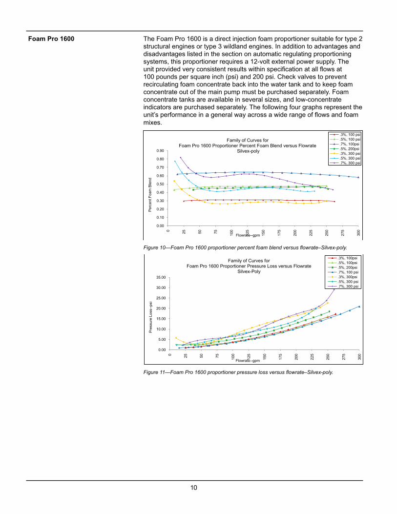
The Foam Pro 1600 is a direct injection foam proportioner suitable for type 2 structural engines or type 3 wildland engines. In addition to advantages and disadvantages listed in the section on automatic regulating proportioning systems, this proportioner requires a 12-volt external power supply. The unit provided very consistent results within specification at all flows at 100 pounds per square inch (psi) and 200 psi. Check valves to prevent recirculating foam concentrate back into the water tank and to keep foam concentrate out of the main pump must be purchased separately. Foam concentrate tanks are available in several sizes, and low-concentrate indicators are purchased separately. The following four graphs represent the unit’s performance in a general way across a wide range of flows and foam mixes.
Figure 10—Foam Pro 1600 proportioner percent foam blend versus flowrate–Silvex-poly.
Figure 11—Foam Pro 1600 proportioner pressure loss versus flowrate–Silvex-poly.
Foam Pro 1600
0.00
0.10
0.20
0.30
0.40
0.50
0.60
0.70
0.80
0.90
0 25 50 75
100
125
150
175
200
225
250
275
300
Per
cent
Foa
m B
lend
Flowrate--gpm
Family of Curves for Foam Pro 1600 Proportioner Percent Foam Blend versus Flowrate
Silvex-poly
.3%, 100 psi
.5%, 100 psi
.7%, 100psi
.5%, 200psi
.3%, 300 psi
.5%, 300 psi
.7%, 300 psi
0.00
5.00
10.00
15.00
20.00
25.00
30.00
35.00
0 25 50 75 100
125
150
175
200
225
250
275
300
Pre
ssur
e Lo
ss--
psi
Flowrate--gpm
Family of Curves for Foam Pro 1600 Proportioner Pressure Loss versus Flowrate
Silvex-Poly
.3%, 100psi
.5%, 100psi
.5%, 200psi
.7%, 100 psi
.3%, 300psi
.5%, 300 psi
.7%, 300 psi
11
Figure 12—Foam Pro 1600 proportioner percent foam blend versus flowrate–Firechoke.
Figure 13—Foam Pro 1600 proportioner pressure loss versus flowrate–Firechoke.
0.00
0.10
0.20
0.30
0.40
0.50
0.60
0.70
0 25 50 75 100
125
150
175
200
225
250
275
300
Per
cent
Foa
m B
lend
Flowrate--gpm
Family of Curves for Foam Pro 1600 Proportioner Percent Foam Blend versus Flowrate
Firechoke
.5%, 100psi
.5%, 200psi
0.00
5.00
10.00
15.00
20.00
25.00
30.00
0 25 50 75 100
125
150
175
200
225
250
275
300
Pre
ssur
e Lo
ss--
psi
Flowrate--gpm
Family of Curves for Foam Pro 1600 Proportioner Pressure Loss versus Flowrate
Firechoke
.5%, 100psi
.5%, 200psi
12
The Foam Pro 1601 is a direct injection foam proportioner suitable for type 2 structural engines or type 3 wildland engines. In addition to advantages and disadvantages listed in the section on automatic regulating proportioning systems, this proportioner requires a 12-volt external power supply. This unit was tested only at 300 psi, however, results at lower pressures should be nearly the same as the Foam Pro 1600. The only difference between the Foam Pro 1600 and 1601 is the capacity of the foam concentrate pump. The 1600’s concentrate pump is capable of pumping 1.7 gpm while the 1601 pumps 1.0 gpm. The Foam Pro 1600 is capable of mixing higher percentages of mixed foam, which is not necessary for Forest Service use. Check valves to prevent recirculating foam concentrate back into the water tank and to keep foam concentrate out of the main pump must be purchased separately. Foam concentrate tanks are available in several sizes, and low-concentrate indicators are purchased separately. The following two graphs represent the unit’s performance in a general way across a wide range of flows and foam mixes.
Figure 14—Foam Pro 1601 proportioner percent foam blend versus flowrate–Silvex-poly.
Figure 15—Foam Pro 1601 proportioner pressure loss versus flowrate–Silvex-poly.
Foam Pro 1601
0.00
0.10
0.20
0.30
0.40
0.50
0.60
0.70
0.80
0.90
0 25 50 75 100
125
150
175
200
225
250
275
300
Per
cent
Foa
m B
lend
Flowrate--gpm
Family of Curves for Foam Pro 1601 Proportioner Percent Foam Blend versus Flowrate
Silvex-poly
.3%, 300 psi
.5%, 300 psi
.7%, 300 psi
0.00
5.00
10.00
15.00
20.00
25.00
30.00
35.00
0 25 50 75 100
125
150
175
200
225
250
275
300
Pre
ssur
e Lo
ss--
psi
Flowrate--gpm
Family of Curves for Foam Pro 1601 Proportioner Pressure Loss versus Flowrate
Silvex-Poly
.3%, 300psi
.5%, 300 psi
.7%, 300 psi
13
The Foam Pro 2001 is a direct injection foam proportioner suitable for type 2 structural engines or type 3 wildland engines. In addition to advantages and disadvantages listed in the section on automatic regulating proportioning systems, this proportioner requires a 12-volt external power supply. The unit provided very consistent results, with the exception of the 300 psi and 0.7-percent foam blend operating condition. SDTDC performed this test a second time to verify this result. The unit apparently does not perform well at high pressure when using a rich foam blend. Check valves to prevent recirculating foam concentrate back into the water tank and to keep foam concentrate out of the main pump are included with the proportioner. Foam concentrate tanks are available in several sizes; low-concentrate indicators are purchased separately. The following two graphs represent the unit’s performance in a general way across a wide range of flows and foam mixes.
Figure 16—Foam Pro 2001 proportioner percent foam blend versus flowrate–Silvex.
Figure 17—Foam Pro 2001 proportioner pressure loss versus flowrate–Silvex.
Foam Pro 2001
0
0.2
0.4
0.6
0.8
1
1.2
1.4
1.6
1.8
0 25 50 75 100
125
150
175
200
225
250
275
300
Per
cent
Foa
m B
lend
Flowrate--gpm
Family of Curves for Foam Pro 2001 Proportioner Percent Foam Blend versus Flowrate
Silvex
.3%, 100 psi
.3%, 300 psi
.5%, 100psi
.5%, 300psi
.7%. 100psi
.7%. 300psi
0
2
4
6
8
10
12
14
16
0 25 50 75 100
125
150
175
200
225
250
275
300
Pre
ssur
e Lo
ss--
psi
Flowrate--gpm
Family of Curves for Foam Pro 2001 Proportioner Pressure Loss versus Flowrate
Silvex
.3%, 100psi
.3%, 300psi
.5%, 100psi
.5%, 300ps
.7%, 100psi
.7%, 300psi
14
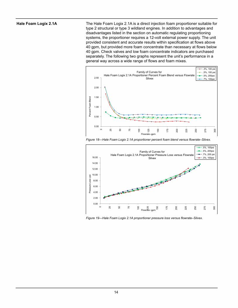
The Hale Foam Logix 2.1A is a direct injection foam proportioner suitable for type 2 structural or type 3 wildland engines. In addition to advantages and disadvantages listed in the section on automatic regulating proportioning systems, the proportioner requires a 12-volt external power supply. The unit provided consistent and accurate results within specification at flows above 40 gpm, but provided more foam concentrate than necessary at flows below 40 gpm. Check valves and low foam concentrate indicators are purchased separately. The following two graphs represent the unit’s performance in a general way across a wide range of flows and foam mixes.
Figure 19—Hale Foam Logix 2.1A proportioner pressure loss versus flowrate–Silvex.
Hale Foam Logix 2.1A
0.00
0.50
1.00
1.50
2.00
2.50
0 25 50 75 100
125
150
175
200
225
250
275
300
Per
cent
Foa
m B
lend
Flowrate--gpm
Family of Curves for Hale Foam Logix 2.1A Proportioner Percent Foam Blend versus Flowrate
Silvex
.3%, 100 psi
.5%, 100 psi
.5%, 200psi
.7%, 100psi
0.00
2.00
4.00
6.00
8.00
10.00
12.00
14.00
16.00
0 25 50 75 100
125
150
175
200
225
250
275
300
Pre
ssur
e Lo
ss--
psi
Flowrate--gpm
Family of Curves for Hale Foam Logix 2.1A Proportioner Pressure Loss versus Flowrate
Silvex
.5%, 100psi
.5%, 200psi
.7%, 200 psi
.3%, 100psi
15
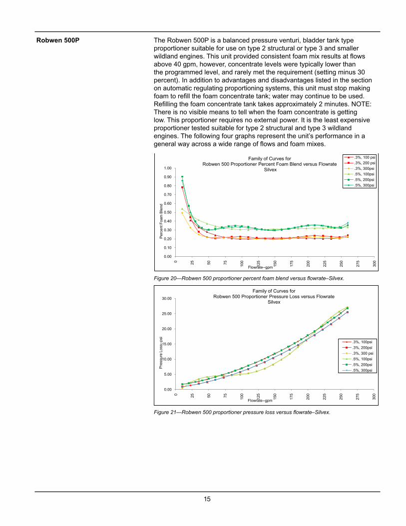
The Robwen 500P is a balanced pressure venturi, bladder tank type proportioner suitable for use on type 2 structural or type 3 and smaller wildland engines. This unit provided consistent foam mix results at flows above 40 gpm, however, concentrate levels were typically lower than the programmed level, and rarely met the requirement (setting minus 30 percent). In addition to advantages and disadvantages listed in the section on automatic regulating proportioning systems, this unit must stop making foam to refill the foam concentrate tank; water may continue to be used. Refilling the foam concentrate tank takes approximately 2 minutes. NOTE: There is no visible means to tell when the foam concentrate is getting low. This proportioner requires no external power. It is the least expensive proportioner tested suitable for type 2 structural and type 3 wildland engines. The following four graphs represent the unit’s performance in a general way across a wide range of flows and foam mixes.
Figure 20—Robwen 500 proportioner percent foam blend versus flowrate–Silvex.
Figure 21—Robwen 500 proportioner pressure loss versus flowrate–Silvex.
Robwen 500P
0.00
0.10
0.20
0.30
0.40
0.50
0.60
0.70
0.80
0.90
1.00
0 25 50 75 100
125
150
175
200
225
250
275
300
Per
cent
Foa
m B
lend
Flowrate--gpm
Family of Curves for Robwen 500 Proportioner Percent Foam Blend versus Flowrate
Silvex
.3%, 100 psi
.3%, 200 psi
.3%, 300psi
.5%, 100psi
.5%, 200psi
.5%, 300psi
0.00
5.00
10.00
15.00
20.00
25.00
30.00
0 25 50 75 100
125
150
175
200
225
250
275
300
Pre
ssur
e Lo
ss--
psi
Flowrate--gpm
Family of Curves for Robwen 500 Proportioner Pressure Loss versus Flowrate
Silvex
.3%, 100psi
.3%, 200psi
.3%, 300 psi
.5%, 100psi
.5%, 200psi
.5%, 300psi
16
Figure 22—Robwen 500 proportioner percent foam blend versus flowrate–Firechoke.
Figure 23—Robwen 500 proportioner pressure loss versus flowrate–Firechoke.
0.00
0.10
0.20
0.30
0.40
0.50
0.60
0.70
0 25 50 75 100
125
150
175
200
225
250
275
300
Per
cent
Foa
m B
lend
Flowrate--gpm
Family of Curves for Robwen 500 Proportioner Percent Foam Blend versus Flowrate
Firechoke
.5%, 100psi
.5%, 200psi
0.00
5.00
10.00
15.00
20.00
25.00
30.00
0 25 50 75 100
125
150
175
200
225
250
275
300
Pre
ssur
e Lo
ss--
psi
Flowrate--gpm
Family of Curves for Robwen 500 Proportioner Pressure Loss versus Flowrate
Firechoke
.5%, 100psi
.5%, 200psi
17
In general, most of the proportioners provided reasonably consistent performance over a fairly broad range of flows and pressures, the one exception was the Robwen Hydroflow 100. Many of the proportioners, while providing consistent results, fell outside the allowed +/- 30 percent accuracy. However, in actual use, accuracy is less important than consistency over a broad range of flows, because the operator can adjust the amount of concentrate to achieve the desired mix. Once the desired mix is achieved, it will remain constant over its operating range of pressures and flows. See the section titled proportioner accuracy and economics.
SDTDC tested these units under laboratory conditions; so, long-term reliability and maintenance requirements are unknown. The Robwen Hydroflow 100 was very unreliable and often required disassembling to clean and to replace parts. Therefore, SDTDC does not recommend this unit.
The correct proportioner must be sized for the job, provide accurate and consistent results, and be economically compatible with the system it will be used with. The user should not place an expensive proportioner on a small, inexpensive foam system. In fact, for small and seldom-used foam systems, one should question the need for an expensive automatically adjusting foam proportioner. For example, if the unit is used only occasionally for campfires, mopup, and so forth, a manually adjusting proportioner might be a more reasonable solution. The least expensive automatically adjusting proportioner costs several thousand dollars, while a manual unit is a few hundred dollars.
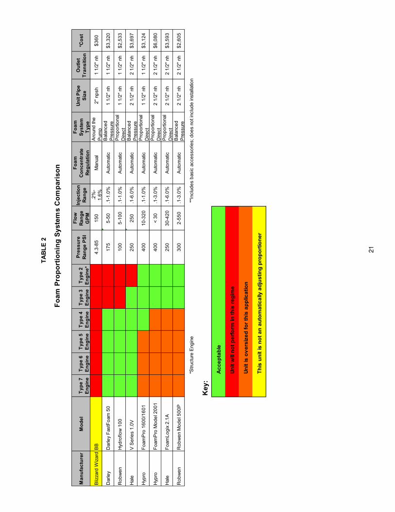
Table 2 provides a visual means to help choose a proportioner. Besides the proportioner’s basic characteristics, the user also must consider how it will be used. If it will be used infrequently, a less expensive unit may be appropriate. However, for demanding applications, such as type 2 structural engines and type 3 wildland engines using complex hose lays, a highly consistent unit may prove beneficial, despite its higher cost.
To decide which proportioner is correct for your particular application, use table 2 to choose the group of proportioners that best fit your application. For instance, if you are looking for a proportioner for a type 4 engine, there are three possible choices: the Darley Fast Foam 50, the Hale V Series 1.0V, and the Foam Pro 1600/1601.
Then, check table 3 to ensure that your choice meets the evaluation criteria.
Finally, use the comparison curves and performance curves for those proportioners in appendix A to make a final choice based on the cost, overall value and performance as well as their advantages and disadvantages.
Performance curves for other SDTDC-tested proportioners are in appendix C.
Conclusions and Recommendations
Considerations for Choosing a Foam Proportioner
Choosing a Proportioner
19
SDTDC thanks the following staff for their technical review of this publication:
Dave Haston, mechanical engineer, senior project leader SDTDCTrevor Maynard, mechanical engineer, SDTDCGeorge Broyles, fire project leader SDTDC
The National Technology and Development Center’s national publications are available on the Internet at<http://www.fs.fed.us/eng/pubs/>.
Forest Service and U.S. Department of the Interior, Bureau of Land Management employees also can view videos, CDs, and National Technology and Development Center’s individual project pages on their internal computer network at <http://fsweb.sdtdc.wo.fs.fed.us/>.
For additional information on foam proportioners contact Ralph Gonzales, fire program leader. Phone: 909–599–1267 ext 212. Email <[email protected]>.
TA
BL
E 2
Fo
am P
rop
ort
ion
ing
Sys
tem
s C
om
par
iso
n
Ma
nu
fac
ture
rM
od
el
Ty
pe
7
En
gin
eT
yp
e 6
E
ng
ine
Ty
pe
5
En
gin
eT
yp
e 4
E
ng
ine
Ty
pe
3
En
gin
eT
yp
e 2
E
ng
ine
*
Pre
ss
ure
R
an
ge
PS
I
Flo
w
Ra
ng
e
GP
M
Inje
cti
on
R
an
ge
Fo
am
C
on
ce
ntr
ate
Re
gu
lati
on
Fo
am
S
ys
tem
T
yp
e
Un
it P
ipe
S
ize
Ou
tle
t T
ran
sit
ion
*Co
st
Bliz
zard
Wiz
ard
BB
4.3
-85
15
0.2
%-
1.6
%M
anua
lA
roun
d th
e
Pum
p2
" np
sh1
1/2
" nh
$3
60
Dar
ley
Dar
ley
Fas
tFo
am 5
01
75
5-5
0.1
-1.0
%A
uto
mat
icB
alan
ced
P
ress
ure
1
1/2
" nh
1 1
/2"
nh$
3,3
20
Ro
bw
en
Hyd
roflo
w 1
00
10
05
-10
0.1
-1.0
%A
uto
mat
icP
rop
ort
iona
l D
irect
1
1/2
" nh
1 1
/2"
nh$
2,5
33
Hal
eV
Se
ries
1.0
V2
50
25
0.1
-6.0
%A
uto
mat
icB
alan
ced
P
ress
ure
2
1/2
" nh
2 1
/2"
nh$
3,6
97
Hyp
roF
oam
Pro
16
00
/16
01
40
01
0-3
20
.1-1
.0%
Aut
om
atic
Pro
po
rtio
nal
Dire
ct
1 1
/2"
nh1
1/2
" nh
$3
,12
4
Hyp
roF
oam
Pro
Mo
de
l 20
01
40
0<
30
.1-3
.0%
Aut
om
atic
Pro
po
rtio
nal
Dire
ct
2 1
/2"
nh2
1/2
" nh
$6
,08
0
Hal
eF
oam
Lo
gix
2.1
A2
50
30
-42
0.1
-6.0
%A
uto
mat
icP
rop
ort
iona
l D
irect
2
1/2
" nh
2 1
/2"
nh$
3,5
93
Ro
bw
en
Ro
bw
en
Mo
de
l 50
0P
30
02
-55
0.1
-3.0
%A
uto
mat
icB
alan
ced
P
ress
ure
2
1/2
" nh
2 1
/2"
nh$
2,6
05
*Str
uctu
re E
ngin
e *
*Inc
lud
es
bas
ic a
cce
sso
ries;
do
es
not i
nclu
de
inst
alla
tion
Key
:
Ac
ce
pta
ble
Un
it w
ill n
ot
pe
rfo
rm in
th
is r
eg
ime
Un
it is
ov
ers
ize
d f
or
this
ap
plic
ati
on
Th
is u
nit
is n
ot
an
au
tom
ati
ca
lly a
dju
sti
ng
pro
po
rtio
ne
r
21
22
TAB
LE 3
PR
OP
OR
TIO
NE
R
EV
ALU
AT
ION
CR
ITE
RIA
Darley Fast Foam 50
Robwen Hydroflow 100
Hale V Series 1.0V
Hypro Foam Pro
1600
Hypro Foam Pro
1601
Hypro Foam Pro
2001
Hale Foam Logix
2.1A
Robwen 500p
Item
Des
crip
tion
Yes No
N/A
Not
Te
sted
Yes No
N/A
Not
Te
sted
Yes No
N/A
Not
Te
sted
Yes No
N/A
Not
Te
sted
Yes No
N/A
Not
Te
sted
Yes No
N/A
Not
Te
sted
Yes No
N/A
Not
Te
sted
Yes No
N/A
Not
Te
sted
1T
he p
ropo
rtio
ning
uni
t ave
rage
acc
urac
y is
with
in +
/- 3
0% o
f eac
h se
tting
.N
O—
SE
E P
ER
FO
RM
AN
CE
CU
RV
ES
2T
he p
ropo
rtio
ning
uni
t acc
urac
y is
not
sig
nific
antly
affe
cted
by
chan
ges
in fl
ow
rate
.N
O—
SE
E P
ER
FO
RM
AN
CE
CU
RV
ES
3T
he p
ropo
rtio
ning
uni
t acc
urac
y is
not
sig
nific
antly
affe
cted
by
chan
ges
in
upst
ream
pre
ssur
e.Y
NY
YY
YY
Y
4T
he c
once
ntra
te v
isco
sity
doe
s no
t affe
ct th
e pr
opor
tioni
ng u
nit a
ccur
acy.
NN
NN
NN
NN
5T
he p
ropo
rtio
ning
uni
t doe
s no
t req
uire
add
ing
foam
con
cent
rate
to th
e fir
e en
gine
wat
er r
eser
voir.
YY
YY
YY
YY
6T
he p
ropo
rtio
ner
unit
does
not
req
uire
that
foam
con
cent
rate
pas
s th
roug
h th
e fir
e en
gine
pum
p.Y
YY
YY
YY
Y
7T
he p
ropo
rtio
ner
ensu
res
foam
con
cent
rate
can
not c
onta
min
ate
the
fire
engi
ne
wat
er r
eser
voir,
sys
tem
plu
mbi
ng o
r pu
mp.
YY
YY
YY
YY
8T
he p
ropo
rtio
ner
does
not
req
uire
ser
vice
mor
e th
an o
nce
per
year
.N
TN
TN
TN
TN
TN
TN
TN
T
9T
he p
ropo
rtio
ner
prov
ides
an
indi
cato
r th
at te
lls th
e op
erat
or h
ow m
uch
foam
co
ncen
trat
e re
mai
ns in
the
syst
em fo
r us
e.Y
ES
, HO
WE
VE
R IN
DIC
AT
OR
S A
RE
PU
RC
HA
SE
D
SE
PA
RA
TE
LYN
10T
he p
ress
ure
loss
acr
oss
the
prop
ortio
ner
unit
is le
ss th
an 2
0 ps
id a
t a fl
ow o
f 30
0 gp
m.
SE
E P
ER
FO
RM
AN
CE
CU
RV
ES
11T
he p
ropo
rtio
ner
unit
requ
ires
less
than
40
amps
of a
vera
ge c
urre
nt to
pro
vide
its
pow
er.
YN
/AY
YY
YY
N/A
12T
he p
ropo
rtio
ner
unit
is c
onst
ruct
ed o
f mat
eria
ls th
at a
re c
ompa
tible
with
foam
s w
hen
it is
rou
tinel
y flu
shed
.Y
YY
YY
YY
Y
13T
he p
ropo
rtio
ner
conc
entr
ate
rese
rvoi
r ca
n be
refi
lled
whi
le it
is o
pera
ting.
YY
YY
YY
YN
14P
ropo
rtio
ner
mix
rat
ios
can
be e
asily
adj
uste
d.
YY
YY
YY
YY
15T
he p
ropo
rtio
ner
can
accu
rate
ly u
se d
iffer
ent t
ypes
of f
oam
con
cent
rate
s ei
ther
cl
ass
“A”
(US
DA
For
est S
ervi
ce a
ppro
ved)
or
clas
s “B
,” a
t up
to 1
per
cent
co
ncen
trat
ion.
NT
NT
NT
NT
NT
NT
NT
NT
22
23
APPENDIX A.PROPORTIONAL TEST RESULTS AND PERFORMANCE CURVESCOMPARISON CURVES
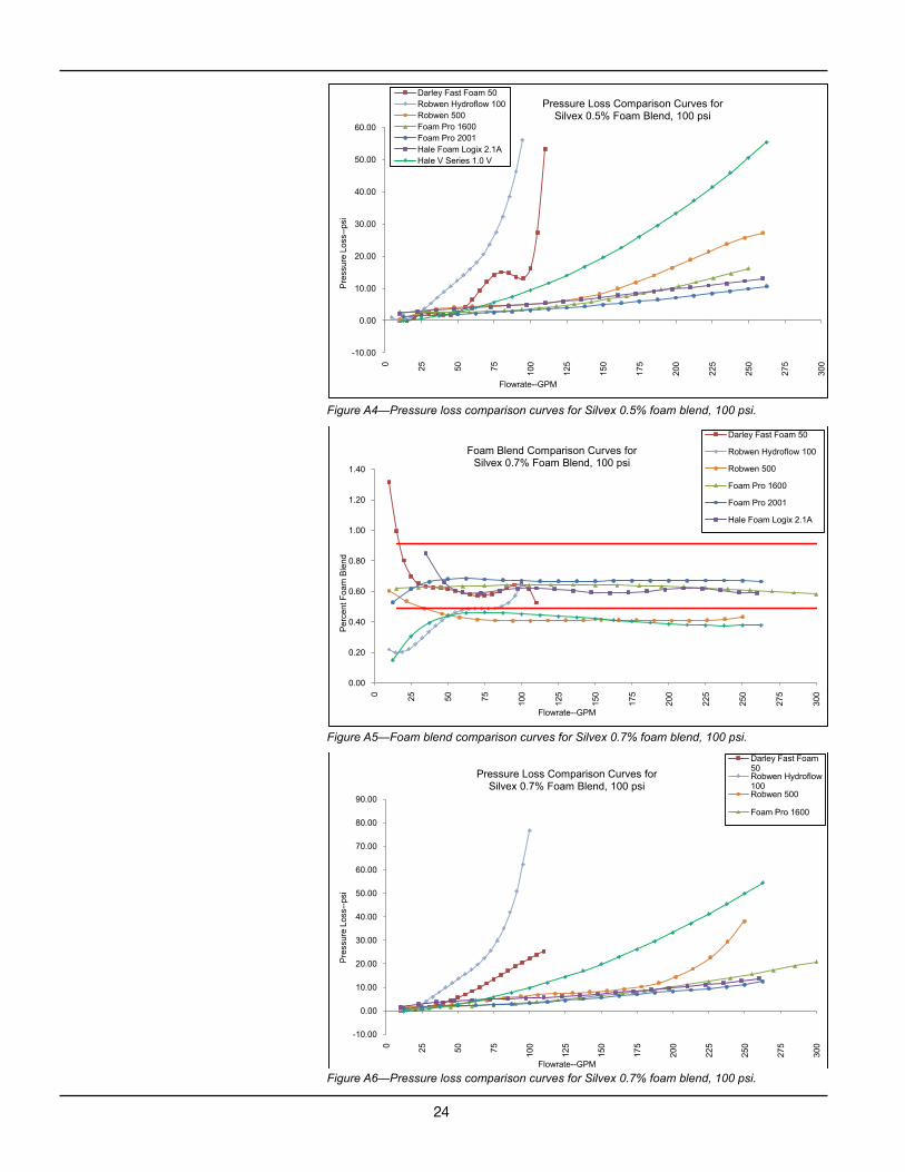
Figure A8—Pressure loss comparison curves for 0.7% foam blend, 300 psi.
Figure A9—Foam blend comparison curves for Firechoke.
0.00
0.20
0.40
0.60
0.80
1.00
1.20
1.40
1.60
1.80
0 25 50 75 100
125
150
175
200
225
250
275
300
Per
cent
Foa
m B
lend
Flowrate--GPM
Foam Blend Comparison Curves for 0.7% Foam Blend, 300 psi
Robwen 500
Foam Pro 1601
Foam Pro 2001
0.7% Foam Blend plus 30%0.7% Foam Blend minus 30%
-5.00
0.00
5.00
10.00
15.00
20.00
25.00
30.00
35.00
0 25 50 75 100
125
150
175
200
225
250
275
300
Pre
ssur
e Lo
ss--
psi
Flowrate--GPM
Pressure Loss Comparison Curves for0.7% Foam Blend, 300 psi
Robwen 500
Foam Pro 1601
Foam Pro 2001
0.00
0.20
0.40
0.60
0.80
1.00
1.20
0 25 50 75 100
125
150
175
200
225
250
275
300
Per
cent
Foa
m B
lend
Flowrate--GPM
Foam Blend Comparison Curves for Firechoke
Foam Pro 1600 .5% 100psiFoam Pro 1600 .5% 200psiFoam Pro 2001 .5% 100psiFoam Pro 2001 .5% 200psiRobwen 500 .3% 100psiRobwen 500 .3%, 200psi.5% plus 30%
26
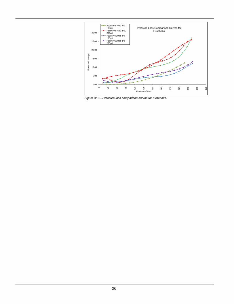
Figure A10—Pressure loss comparison curves for Firechoke.
0.00
5.00
10.00
15.00
20.00
25.00
30.00
0 25 50 75
100
125
150
175
200
225
250
275
300
Pre
ssur
e Lo
ss--
psi
Flowrate--GPM
Pressure Loss Comparison Curves forFirechoke
Foam Pro 1600 .5% 100psiFoam Pro 1600 .5%, 200psiFoam Pro 2001 .5% 100psiFoam Pro 2001 .5% 200psi
27
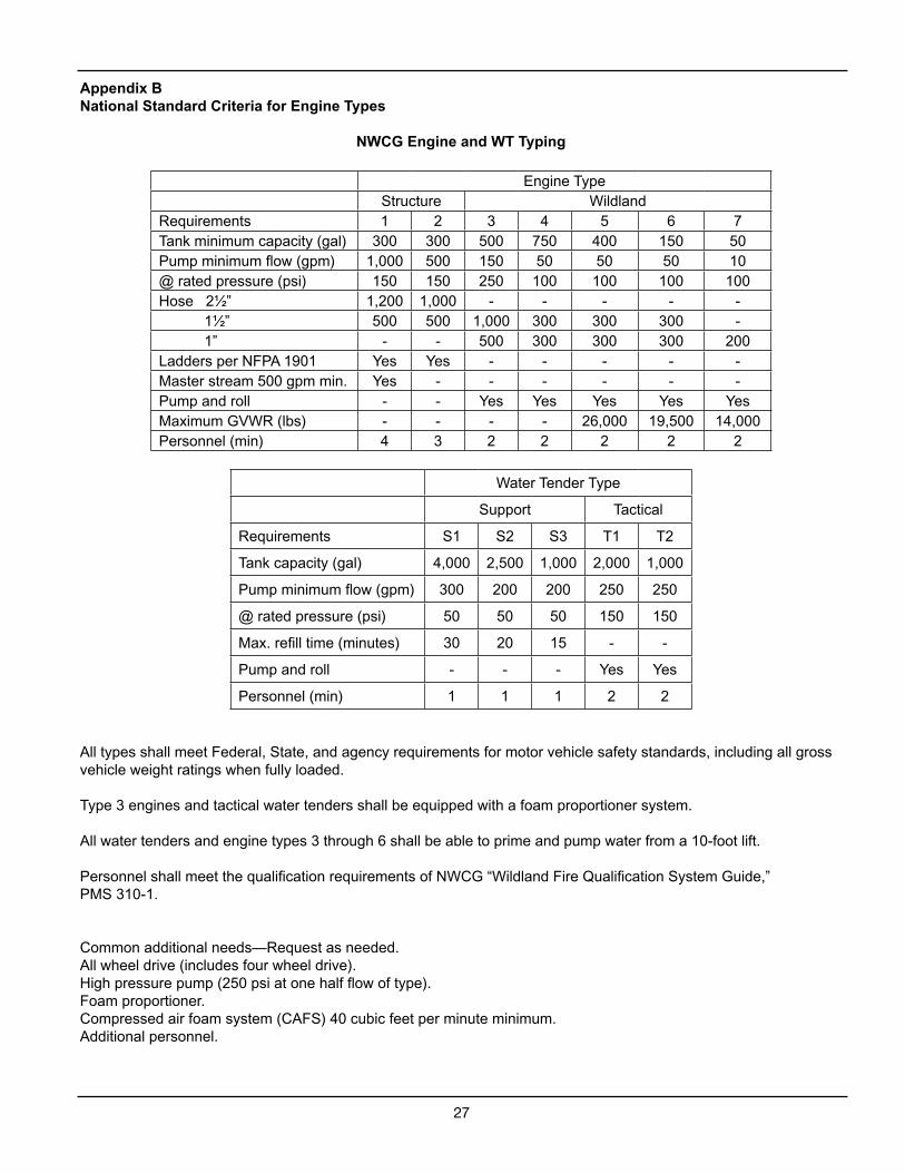
Appendix BNational Standard Criteria for Engine Types
All types shall meet Federal, State, and agency requirements for motor vehicle safety standards, including all gross vehicle weight ratings when fully loaded.
Type 3 engines and tactical water tenders shall be equipped with a foam proportioner system.
All water tenders and engine types 3 through 6 shall be able to prime and pump water from a 10-foot lift.
Personnel shall meet the qualification requirements of NWCG “Wildland Fire Qualification System Guide,” PMS 310-1.
Common additional needs—Request as needed.All wheel drive (includes four wheel drive).High pressure pump (250 psi at one half flow of type).Foam proportioner.Compressed air foam system (CAFS) 40 cubic feet per minute minimum.Additional personnel.
29
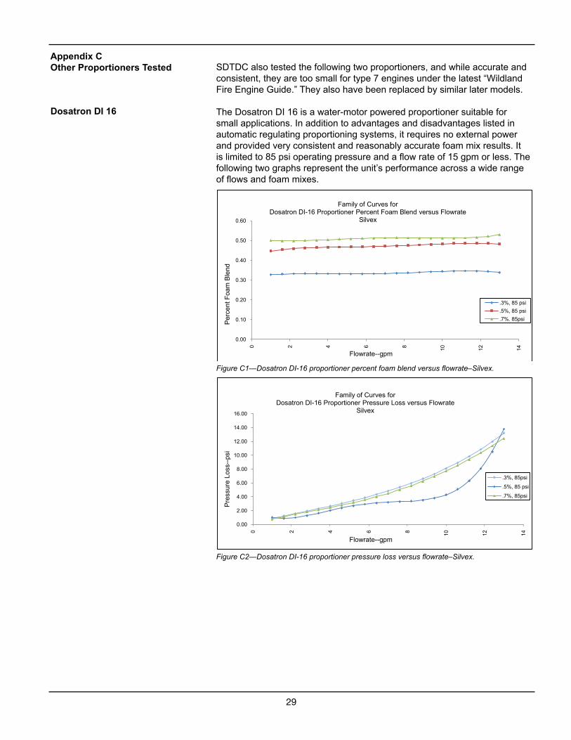
SDTDC also tested the following two proportioners, and while accurate and consistent, they are too small for type 7 engines under the latest “Wildland Fire Engine Guide.” They also have been replaced by similar later models.
The Dosatron DI 16 is a water-motor powered proportioner suitable for small applications. In addition to advantages and disadvantages listed in automatic regulating proportioning systems, it requires no external power and provided very consistent and reasonably accurate foam mix results. It is limited to 85 psi operating pressure and a flow rate of 15 gpm or less. The following two graphs represent the unit’s performance across a wide range of flows and foam mixes.
Figure C1—Dosatron DI-16 proportioner percent foam blend versus flowrate–Silvex.
Figure C2—Dosatron DI-16 proportioner pressure loss versus flowrate–Silvex.
Appendix COther Proportioners Tested
Dosatron DI 16
0.00
0.10
0.20
0.30
0.40
0.50
0.60
0 2 4 6 8 10 12 14
Per
cent
Foa
m B
lend
Flowrate--gpm
Family of Curves for Dosatron DI-16 Proportioner Percent Foam Blend versus Flowrate
Silvex
.3%, 85 psi
.5%, 85 psi
.7%. 85psi
0.00
2.00
4.00
6.00
8.00
10.00
12.00
14.00
16.00
0 2 4 6 8 10 12 14
Pre
ssur
e Lo
ss--
psi
Flowrate--gpm
Family of Curves for Dosatron DI-16 Proportioner Pressure Loss versus Flowrate
Silvex
.3%, 85psi
.5%, 85 psi
.7%, 85psi
30
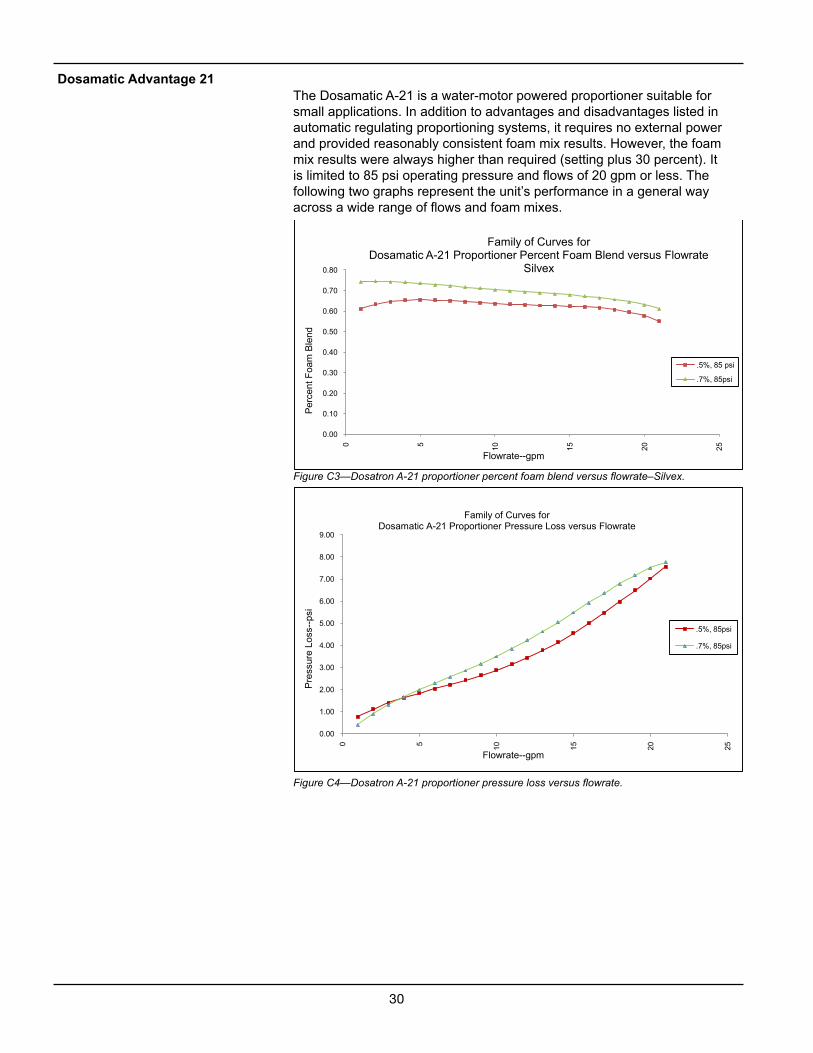
The Dosamatic A-21 is a water-motor powered proportioner suitable for small applications. In addition to advantages and disadvantages listed in automatic regulating proportioning systems, it requires no external power and provided reasonably consistent foam mix results. However, the foam mix results were always higher than required (setting plus 30 percent). It is limited to 85 psi operating pressure and flows of 20 gpm or less. The following two graphs represent the unit’s performance in a general way across a wide range of flows and foam mixes.
Figure C3—Dosatron A-21 proportioner percent foam blend versus flowrate–Silvex.
Figure C4—Dosatron A-21 proportioner pressure loss versus flowrate.
0.00
0.10
0.20
0.30
0.40
0.50
0.60
0.70
0.80
0 5 10 15 20 25
Per
cent
Foa
m B
lend
Flowrate--gpm
Family of Curves for Dosamatic A-21 Proportioner Percent Foam Blend versus Flowrate
Silvex
.5%, 85 psi
.7%, 85psi
Dosamatic Advantage 21
0.00
1.00
2.00
3.00
4.00
5.00
6.00
7.00
8.00
9.00
0 5 10 15 20 25
Pre
ssur
e Lo
ss--
psi
Flowrate--gpm
Family of Curves for Dosamatic A-21 Proportioner Pressure Loss versus Flowrate
.5%, 85psi
.7%, 85psi
31
APPENDIX DStandard Form Developed To Collect Proportioner Test DataQuestions To Be Answered by the Test Conductor Proportioner Make and Model: ___________________________ Test Conductor: ______________________Date: ____________
Proportioning unit average accuracy:Low flow tests?
High flow tests?
Is the proportioning unit accuracy significantly affected by changes in system flow rate?
Is proportioning unit accuracy affected by the concentrate viscosity?
Does the proportioning unit require that foam concentrate be added to the fire engine water reservoir?
Does the proportioner unit require that foam concentrate pass through the fire engine pump?
Does the proportioner assure that the fire engine water reservoir, system plumbing, and pump cannot be contaminated with concentrate? Explain how.
What is the service required to keep the proportioner unit working properly and how often should this service be done?
Were there any problems experienced during the testing of the proportioner? Explain.
If the proportioner unit has an integral foam concentrate reservoir, can it provide enough foam concentrate to treat 500 gallons at a 0.5 percent injection rate?
Does the proportioner have an indicator that tells the operator how much foam concentrate is left in the system for use? If not, explain how to overcome this problem or if it is a problem.
Does the pressure loss measured across the proportioner unit indicate a problem?
Does the proportioner unit require external power? If yes, explain and discuss any issue this could cause.
Is the proportioner unit constructed of materials that are compatible with foams when it is routinely flushed? If not, describe materials of construction.
Is the proportioner unit recommended for general use by the Forest Service? If not, explain why, considering the Forest Service National Wildland Fire Engine Committee (NWFEC) adopted requirements for foam proportioning systems for use on a Forest Service engine.
Those requirements are as follows:
The proportioning system shall be installed on the fire engine pump discharge (downstream of the pump).
Automatic regulating proportioning systems shall be used on high capability fire engines.
The accuracy of the proportioning system over the operating range of the system shall be +/- 30 percent of the proportioning system setting.
Foam proportioning systems shall be installed so foam concentrate or foam solution cannot return to, or contaminate, the water source (fire engine water storage reservoir [tank], water hydrant, or water draft source).