Focus on Power: Advancements in Ceramic Capacitors
Michael CannonProduct Marketing Dept.
2
APEC 2011: Ceramic Capacitor Update
Topics
1. Materials
2. Construction
3. Applications
Recent advances in material technology and design have allowed multilayer ceramic capacitors (MLCCs) to extend beyond replacing electrolytic capacitors in output filtering applications. While still offering the attributes of ultra low ESR and high ripple current capability, MLCCs with higher effective capacitance, thermal/mechanical robustness, and stability have been developed. These constructions offer many advantages to power applications.
3
APEC 2011: Ceramic Capacitor Update
Major Themes in MLCC TechnologyThe technology themes for MLCC capacitors are strongly tied to material developments and construction techniques. Continued refinements of dielectric powders and internal electrode materials are required for increasing layer counts in these capacitors. Through microstructure control of the functional dielectric phase, improved dispersion of additives, and accurate lamination of smooth layers, the volumetric efficiency of the MLCC capacitor is greatly improved.
APEC 2011 Special Presentation 1.3.1 MLCC Advancements in Ceramic Capacitors March 2011
HiCV Material DevelopmentDielectric grain size reduction typically leads to the shell having an increased role. Increasing the core volume in the grain structure slows dielectric constant reduction with smaller grain size.
5
APEC 2011: Ceramic Capacitor Update
Dielectric Layer Thickness ReductionBeyond merely extending the CV product in the MLCC, reliability is also improved through these technology themes. Albeit with thin dielectric layers, reliability is preserved/improved, by maintaining/increasing the number of grains per dielectric layer.
6
APEC 2011: Ceramic Capacitor Update
[200][002]0.50um
0.45um
0.35um
0.30um
0.25um
0.20um
0.15um
0.10um
Particle size
0
500
1000
1500
2000
2500
3000
3500
0 0.2 0.4 0.6
grain size
ε
Grain size [um]
Die
lect
ric c
onst
ant
0.2μm0.2μm
0.35μm0.35μm
0.2μm0.2μm
0.2μm0.2μm
0.2μm0.2μm0.2μm
0.15μm0.15μm
Fine BaTiO3 is required in order to compose the thinner dielectric.However, permittivity of BaTiO3 is reduced in smaller grain sizes. Both crystal anisotropy and crystallinity of BaTiO3 decrease with particle size.
BaTiO3 crystallinity improvements become more important for sub-micron high-K dielectric layer designs.
BaTiO3 Powder DevelopmentWithin a material set, as barium titanate grain sizes decrease, crystallinity decreases leading to the dielectric constant being lower. The amount of capacitance per MLCC layer is reduced.
APEC 2011 Special Presentation 1.3.1 MLCC Advancements in Ceramic Capacitors March 2011
Development of New MaterialImprovement of crystallinity of BaTiO3
-5000
0
5000
10000
15000
20000
25000
30000
44.0 44.5 45.0 45.5 46.0
2θ (deg)
Cou
nt (
Kcp
s)
New BT
Current BT
Using high crystallinity (c/a) BaTiO3 and optimizing formulation. Grain size was decreased, while to maintaining the same permittivity of current material.
K=3000 @ 0.25um ⇒ K=4100 @0.25um
K=4000 @ 0.30um ⇒ K=4100 @0.25um
To overcome the drop in capacitance per layer, barium titanate grains with larger core volume (optimized microstructure) is used.
8
APEC 2011: Ceramic Capacitor Update
0
5
10
15
20
1 2 3 4 5 6 7
Analysis point
RE (AT%)● HALT 208hr● HALT 0hr
Grain boundary
TEM-EDS analysis of high-K dielectric
Concentration of Rare-earth additives around grain boundary is the most important factor for improving HALT result.
Design of Grain BoundaryReliability is directly related to the integrity of the grain boundaries in the ceramic layers.
9
APEC 2011: Ceramic Capacitor Update
Improved Additive DispersionSuperior dispersion of coating materials in green sheet
The traditional method of mixing dielectric and additive powders together has limited effectiveness. Coating the dielectric with the additives, on a liquid scale, prevents low insulation resistance regions caused by agglomeration of the additives. Coating processes provide even coverage on the grain surface.
APEC 2011 Special Presentation 1.3.1 MLCC Advancements in Ceramic Capacitors March 2011
HALT: Additive Method ComparisonAdditive coating materials provide 6x lifetime when compared to the powder slurry mixing method.
Conventional mixing materials
Coating material
The improvement in HALT results indicates that the improved dispersion and even coating of additives on the dielectric grains is very effective. These failures are based on 10x increase in leakage current.
11
APEC 2011: Ceramic Capacitor Update
Conventional mixing materials
950
669
0
200
400
600
800
1000
1200
Brea
k D
own
Volta
ge /
V
99.999.090.063.250.030.0
10.05.03.0
1.00.50.3
0.1
-8.0
-7.0
-6.0
-5.0
-4.0
-3.0
-2.0
-1.0
0.0
1.0
2.0
10 100 1000
Break Down Voltage / V
ln(ln
(1/(1
-F)))
Ft(%
)
Breakdown Voltage: Additive Method Comparison
Coating material
Coating material
Conventionalmixing materials
Breakdown voltage is improved by coating method
Breakdown voltage level and variation are improved. Failures here are based on true rupture of the dielectric (100V/sec)…usually audible cracking.
12
APEC 2011: Ceramic Capacitor Update
Thin Layer DevelopmentThe MLCC construction quality is also dependent upon the electrode characteristics. Closely matching the firing profile performance of the electrode and the dielectric creates fewer gaps. Ceramic particle loading of the electrode paste improves the mechanical strength of the fired body.
APEC 2011 Special Presentation 1.3.1 MLCC Advancements in Ceramic Capacitors March 2011
Improved dispersion technique + high accuracy coating
1um1um
Packing density : 56% Packing density : 62%
Better dispersion of additives = better reliability.
*EPMA Mapping on surface of green sheet
MTTF 0.8hr MTTF:1.8hr MTTF:7.0hr
- Better uniformity -- Worse uniformity -
Packing density : 63%
1um
Optimization of MicrostructureDispersion of additives and consistent layer thicknesses eliminates electric field concentrations, improving long-term reliability and dielectric strength. The MLCC’s volumetric efficiency gains through the improved packing density.
14
APEC 2011: Ceramic Capacitor Update
MLCC Technology RoadmapIn particular, high CV MLCC capacitors have undergone remarkable case size reductions. Additionally, lower circuit voltages have allowed for lower rated voltage capacitors. The combined effect is great board space savings and improved cost-effectiveness.
15
APEC 2011: Ceramic Capacitor Update
MLCC HiCV ProgressionThe market is driven to provide high effective capacitance in small case sizes.
APEC 2011 Special Presentation 1.3.1 MLCC Advancements in Ceramic Capacitors March 2011
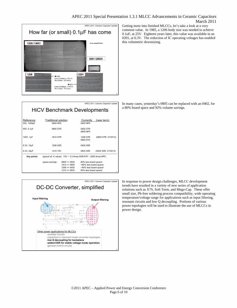
How far (or small) 0.1μF has comeGetting more into finished MLCCs, let’s take a look at a very common value. In 1985, a 1206 body size was needed to achieve 0.1uF, at 25V. Eighteen years later, this value was available in an 0201, at 6.3V. The reduction of IC operating voltages has enabled this volumetric downsizing.
17
APEC 2011: Ceramic Capacitor Update
HiCV Benchmark Developments
Reference Traditional solution Currently (near term)50V, 1000pF 0805 NP0 0402 NP0
Key points -typical ref. K values: Y5V ~ 3.5 times X5R/X7R ~ 3500 times NP0
-space savings: 0805 => 0402 80% less board space!1812 => 0805 >80% less board space!1206 => 0402 ~90% less board space!1210 => 0603 85% less board space!
In many cases, yesterday’s 0805 can be replaced with an 0402, for a 80% board space and 92% volume savings.
18
APEC 2011: Ceramic Capacitor Update
DC-DC Converter, simplified
Other power applications for MLCCs-snubber circuits-capacitors in resonant mode converter topologies-low Q decoupling for backplane-added ESR for stable voltage mode operation-general control circuits
Input filtering Output filtering
In response to power design challenges, MLCC development trends have resulted in a variety of new series of application solutions such as X7S, Soft Term, and Mega-Cap. These offer small size, Pb-free soldering process compatibility, wide operating temperature/voltage range for applications such as input filtering, resonant circuits and low Q decoupling. Portions of various power topologies will be used to illustrate the use of MLCCs in power design.
APEC 2011 Special Presentation 1.3.1 MLCC Advancements in Ceramic Capacitors March 2011
Current technology allows for component count and/or case size reduction.
1812 1206, 0805ex.Telecom/Datacom
Typically, these applications require 500V-1kV box film caps, etc.
Current technology allows for MLCCs (and stacks) to be used.
ex. 1uF at 630V in 2 stack 2220 size
For input filtering already using MLCC solutions, technology improvements allow for 2-3 case size reductions. In higher power/voltage applications, it is possible to switch to MLCCs.
20
APEC 2011: Ceramic Capacitor Update
Applications: Output FilteringIt is widely known that MLCCs offer ultra low ESR/high ripple capability and capacitance stability with frequency. For high frequency converters (>100kHz or so), MLCCs can offer greater noise reduction and ripple suppression while using fewer capacitors.
21
APEC 2011: Ceramic Capacitor Update
MLCCs: Tailored for Application Conditions
X7S out of X7R window at temp extremesMost power apps not affected
Growing trend in MLCCs:Higher effective capacitance at operating conditions esp. power supply and CPU/GPU applications.
-capacitance performance versus temperature-capacitance versus DC bias
In general, capacitors are rated at room temperature, low voltage, and low frequency. At the actual operating conditions, capacitor performance is much different. For the power and CPU/GPU markets, MLCC manufacturers are responding with higher performance capacitors. X7S is one example.
APEC 2011 Special Presentation 1.3.1 MLCC Advancements in Ceramic Capacitors March 2011
APEC 2011: Ceramic Capacitor UpdateMLCCs: Tailored for Application Conditions In most cases, having an ESR value in the single digit milliohm range is accepted as an attribute. However, in some power conversion applications, the ESR can be too low. Instability and unwanted oscillation can occur if sufficient ESR (damping resistance) is not present. Power backplane applications, that may use hundreds of MLCCs in parallel, may have stability issues. Adding ESR provides a level load line.
23
APEC 2011: Ceramic Capacitor UpdateMLCCs: Tailored for Application Conditions
|Z|
Freq.
Adding ESR turns the MLCC into an “anti-resonant cap” suitable for low Q decoupling.
24
APEC 2011: Ceramic Capacitor UpdateCrack Mitigation Strategies Post-solder handling of circuit boards (bending, torsion) continues to be the main cause for cracking of SMT components. Strategy one is to use the smallest possible component. This provides the shortest span between solder pads (bending moment) and the best aspect ratio (thickness:length) to resist cracking. Strategy two is to add a lead frame to the component. Three different styles provide varying stress relief to the component body.
APEC 2011 Special Presentation 1.3.1 MLCC Advancements in Ceramic Capacitors March 2011
“Open Mode” or “Fail Safe” Construction*active stack is moved inside of terminal bands
Typically, in MLCCs, the flexure crack propagation path is from the bottom termination edge toward the side edge of the termination. Moving the overlapping portion (active stack) inside of the bottom termination edges, the path is through common electrodes. This preserves insulation resistance.
Two other additional countermeasures are soft termination and floating electrode. Soft term adds a polymeric resin material to the termination layering. This provides significant drop test improvements and 5-10 times board bending versus standard constructions.
Floating electrode is constructed as two series-connected capacitors per layer. Similar to the “open mode” design, the insulation resistance is maintained.
Stacked designs– Double capacitance in same X-Y space– Thermal/mechanical isolation off-the-board– Improved bending performance/reduced piezo noise
Another MLCC cracking countermeasure involves use of a lead frame. MLCCs are attached to a lead frame. Paying special attention to the position of the MLCC on the lead frame is required to minimize thermal and mechanical stresses. Reduced piezo noise is an additional benefit of the proper use of the lead frame construction.
APEC 2011 Special Presentation 1.3.1 MLCC Advancements in Ceramic Capacitors March 2011
MLCC Summary1. Through material advancements, volumetric efficiency (CV product), reliability and stability at actual operating conditions continue significant improvements.
2. Developments in construction have allowed for greater thermal/mechanical robustness and board space savings.
3. MLCCs offer small size, high temp solder/environmental compatibility, and broad temperature/voltage ranges. Principal targets are high power density, high efficiency, and high reliability power applications.
Use of MLCCs with high effective capacitance (at real operating conditions), and high reliability continues to expand in power applications. This is especially so for those applications that require small size, high efficiency/power density, and maintenance-free reliability.