1
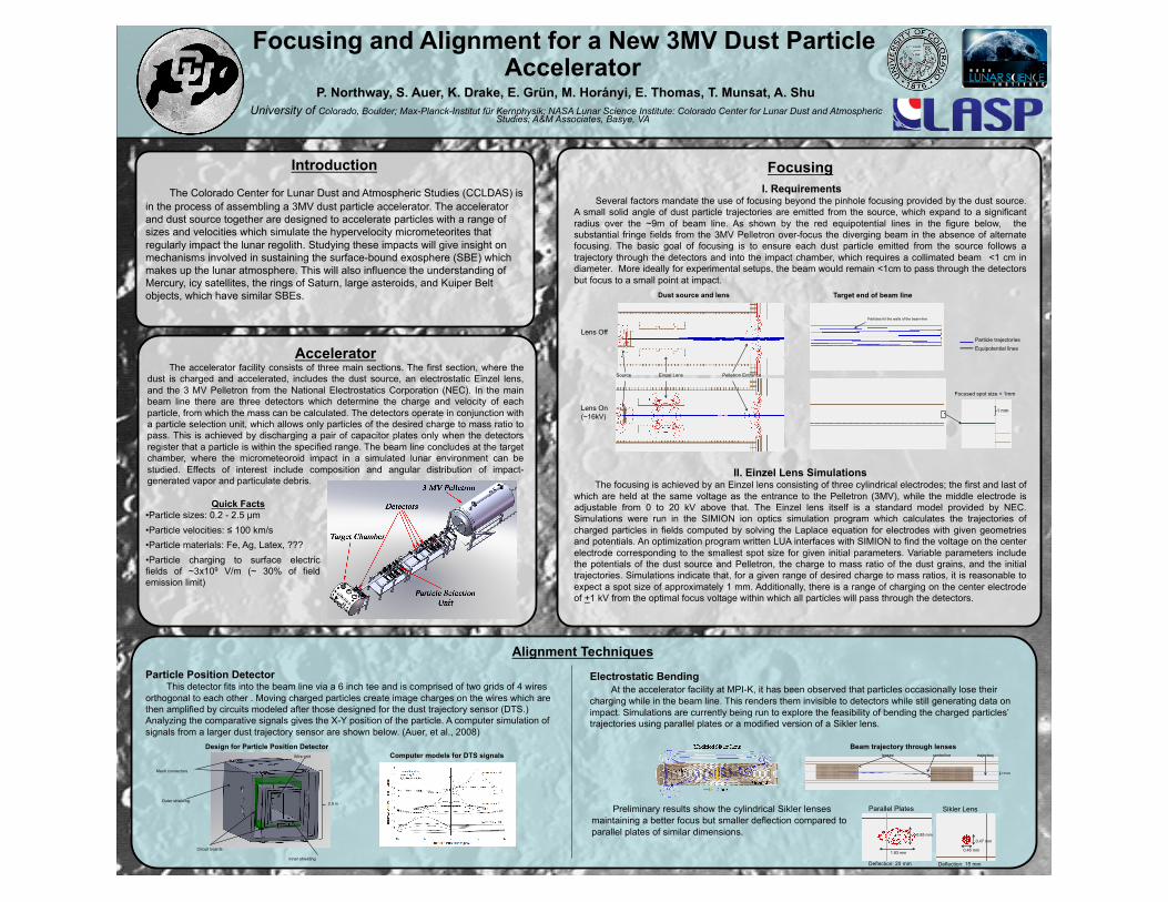
Focusing and Alignment for a New 3MV Dust Particle Accelerator P. Northway, S. Auer, K. Drake, E. Grün, M. Horányi, E. Thomas, T. Munsat, A. Shu University of Colorado, Boulder; Max-Planck-Institut für Kernphysik; NASA Lunar Science Institute: Colorado Center for Lunar Dust and Atmospheric Studies; A&M Associates, Basye, VA Introduction The Colorado Center for Lunar Dust and Atmospheric Studies (CCLDAS) is in the process of assembling a 3MV dust particle accelerator. The accelerator and dust source together are designed to accelerate particles with a range of sizes and velocities which simulate the hypervelocity micrometeorites that regularly impact the lunar regolith. Studying these impacts will give insight on mechanisms involved in sustaining the surface-bound exosphere (SBE) which makes up the lunar atmosphere. This will also influence the understanding of Mercury, icy satellites, the rings of Saturn, large asteroids, and Kuiper Belt objects, which have similar SBEs. Accelerator The accelerator facility consists of three main sections. The first section, where the dust is charged and accelerated, includes the dust source, an electrostatic Einzel lens, and the 3 MV Pelletron from the National Electrostatics Corporation (NEC). In the main beam line there are three detectors which determine the charge and velocity of each particle, from which the mass can be calculated. The detectors operate in conjunction with a particle selection unit, which allows only particles of the desired charge to mass ratio to pass. This is achieved by discharging a pair of capacitor plates only when the detectors register that a particle is within the specified range. The beam line concludes at the target chamber, where the micrometeoroid impact in a simulated lunar environment can be studied. Effects of interest include composition and angular distribution of impact- generated vapor and particulate debris. Focusing I. Requirements Several factors mandate the use of focusing beyond the pinhole focusing provided by the dust source. A small solid angle of dust particle trajectories are emitted from the source, which expand to a significant radius over the ~9m of beam line. As shown by the red equipotential lines in the figure below, the substantial fringe fields from the 3MV Pelletron over-focus the diverging beam in the absence of alternate focusing. The basic goal of focusing is to ensure each dust particle emitted from the source follows a trajectory through the detectors and into the impact chamber, which requires a collimated beam <1 cm in diameter. More ideally for experimental setups, the beam would remain <1cm to pass through the detectors but focus to a small point at impact. II. Einzel Lens Simulations The focusing is achieved by an Einzel lens consisting of three cylindrical electrodes; the first and last of which are held at the same voltage as the entrance to the Pelletron (3MV), while the middle electrode is adjustable from 0 to 20 kV above that. The Einzel lens itself is a standard model provided by NEC. Simulations were run in the SIMION ion optics simulation program which calculates the trajectories of charged particles in fields computed by solving the Laplace equation for electrodes with given geometries and potentials. An optimization program written LUA interfaces with SIMION to find the voltage on the center electrode corresponding to the smallest spot size for given initial parameters. Variable parameters include the potentials of the dust source and Pelletron, the charge to mass ratio of the dust grains, and the initial trajectories. Simulations indicate that, for a given range of desired charge to mass ratios, it is reasonable to expect a spot size of approximately 1 mm. Additionally, there is a range of charging on the center electrode of + 1 kV from the optimal focus voltage within which all particles will pass through the detectors. Alignment Techniques 17mm centerline trajectory lenses Electrostatic Bending At the accelerator facility at MPI-K, it has been observed that particles occasionally lose their charging while in the beam line. This renders them invisible to detectors while still generating data on impact. Simulations are currently being run to explore the feasibility of bending the charged particles’ trajectories using parallel plates or a modified version of a Sikler lens. Parallel Plates Sikler Lens 0.85 mm 1.83 mm 0.47 mm 0.46 mm Deflection: 20 mm Deflection: 15 mm Preliminary results show the cylindrical Sikler lenses maintaining a better focus but smaller deflection compared to parallel plates of similar dimensions. Particle Position Detector This detector fits into the beam line via a 6 inch tee and is comprised of two grids of 4 wires orthogonal to each other . Moving charged particles create image charges on the wires which are then amplified by circuits modeled after those designed for the dust trajectory sensor (DTS.) Analyzing the comparative signals gives the X-Y position of the particle. A computer simulation of signals from a larger dust trajectory sensor are shown below. (Auer, et al., 2008) Computer models for DTS signals Beam trajectory through lenses Circuit boards Wire grid Inner shielding Mesh connectors Design for Particle Position Detector Outer shielding 2.5 in Particles hit the walls of the beam-line Dust source and lens Target end of beam line 1 mm Source Einzel Lens Pelletron Entrance Lens Off Lens On (~16kV) Focused spot size < 1mm Particle trajectories Equipotential lines Quick Facts •Particle sizes: 0.2 - 2.5 μm •Particle velocities: ≤ 100 km/s •Particle materials: Fe, Ag, Latex, ??? •Particle charging to surface electric fields of ~3x10 9 V/m (~ 30% of field emission limit)