Foil Bearing Starting Considerations and Requirements for Rotorcraft Engine Applications by Kevin C. Radil and Christopher DellaCorte ARL-TR-4873 August 2009 Approved for public release; distribution unlimited. https://ntrs.nasa.gov/search.jsp?R=20120012857 2018-05-17T11:40:00+00:00Z
Transcript
Foil Bearing Starting Considerations and Requirements for
Rotorcraft Engine Applications
by Kevin C. Radil and Christopher DellaCorte
ARL-TR-4873 August 2009
Approved for public release; distribution unlimited.
Disclaimers The findings in this report are not to be construed as an official Department of the Army position unless so designated by other authorized documents. Citation of manufacturer’s or trade names does not constitute an official endorsement or approval of the use thereof. Destroy this report when it is no longer needed. Do not return it to the originator.
Army Research Laboratory Cleveland, OH 44135
ARL-TR-4873 August 2009
Foil Bearing Starting Considerations and Requirements for Rotorcraft Engine Applications
Kevin C. Radil
Vehicle Technology Directorate, NASA-Glenn Research Center, ARL
and
Christopher DellaCorte NASA-Glenn Research Center, Cleveland, OH
Approved for public release; distribution unlimited.
ii
REPORT DOCUMENTATION PAGE Form Approved OMB No. 0704-0188
Public reporting burden for this collection of information is estimated to average 1 hour per response, including the time for reviewing instructions, searching existing data sources, gathering and maintaining the data needed, and completing and reviewing the collection information. Send comments regarding this burden estimate or any other aspect of this collection of information, including suggestions for reducing the burden, to Department of Defense, Washington Headquarters Services, Directorate for Information Operations and Reports (0704-0188), 1215 Jefferson Davis Highway, Suite 1204, Arlington, VA 22202-4302. Respondents should be aware that notwithstanding any other provision of law, no person shall be subject to any penalty for failing to comply with a collection of information if it does not display a currently valid OMB control number. PLEASE DO NOT RETURN YOUR FORM TO THE ABOVE ADDRESS.
1. REPORT DATE (DD-MM-YYYY)
August 2009 2. REPORT TYPE
Final 3. DATES COVERED (From - To)
October 2008 to January 2009 4. TITLE AND SUBTITLE
Foil Bearing Considerations and Requirements for Rotorcraft Engine Applications 5a. CONTRACT NUMBER
5b. GRANT NUMBER
5c. PROGRAM ELEMENT NUMBER
6. AUTHOR(S)
Kevin C. Radil (ARL) and Christopher DellaCorte (NASA-Glenn) 5d. PROJECT NUMBER
5e. TASK NUMBER
5f. WORK UNIT NUMBER
7. PERFORMING ORGANIZATION NAME(S) AND ADDRESS(ES)
NASA Glenn Attn: RDRL-VTP-NASA 21000 Brookpark Rd Cleveland, OH 44135
8. PERFORMING ORGANIZATION REPORT NUMBER
ARL-TR-4873
9. SPONSORING/MONITORING AGENCY NAME(S) AND ADDRESS(ES)
10. SPONSOR/MONITOR’S ACRONYM(S)
11. SPONSOR/MONITOR'S REPORT NUMBER(S)
12. DISTRIBUTION/AVAILABILITY STATEMENT
Approved for public release; distribution unlimited.
13. SUPPLEMENTARY NOTES
14. ABSTRACT
Foil gas bearings under development for rotorcraft-sized, hot core engine applications have been susceptible to damage from the slow acceleration and rates typically encountered during the pre-ignition stage in conventional engines. Recent laboratory failures have been assumed to be directly linked to operating foil bearings below their lift-off speed while following conventional startup procedures for the engines. In each instance, the continuous sliding contact between the foils and shaft was believed to thermally overload the bearing and cause the engines to fail. These failures highlight the need to characterize required acceleration rates and minimum operating speeds for these applications. In this report, startup experiments were conducted with a large, rotorcraft engine sized foil bearing under moderate load and acceleration rates to identify the proper start procedures needed to avoid bearing failure. The results showed that a bearing under a 39.4 kPa static load can withstand a modest acceleration rate of 500 rpm/s and excessive loitering below the bearing lift-off speed provided an adequate solid lubricant is present. 15. SUBJECT TERMS
Foil bearing, gas bearing, turbomachinery
16. SECURITY CLASSIFICATION OF: 17. LIMITATION OF ABSTRACT
UU
18. NUMBER OF PAGES
20
19a. NAME OF RESPONSIBLE PERSON
Kevin Radil a. REPORT
Unclassified
b. ABSTRACT
Unclassified
c. THIS PAGE
Unclassified 19b. TELEPHONE NUMBER (Include area code)
(216) 433-5047 Standard Form 298 (Rev. 8/98)
Prescribed by ANSI Std. Z39.18
iii
Contents
List of Figures iv
1. Introduction 1
2. Foil Bearing Description 3
3. Journal Coating 4
4. Test Rig 4
5. Test Plan 5
6. Test Setup and Procedure 5
7. Discussion of Results 6
8. Conclusions 11
9. References 12
Distribution List 13
iv
List of Figures
Figure 1. Generation I overlapping leaf-type foil air bearing. ........................................................4
Figure 2. Slow-speed foil bearing test rig. ......................................................................................5
Figure 3. Bearing break-away torque for loads from 44.5 to 266.9 N. The y-intercept represents the break-away torque caused by the preload in the bearing. ...................................7
Figure 4. Setup to determine the foil bearing’s lift-off speed while supporting 266.9 N. ..............8
Figure 5. Time history plot of start-stop interval 76–100. ..............................................................8
Figure 6. Bearing after 100 start-stop cycles showing removal of soft polymer from top foils. ....9
Figure 7. PS304 coated journal after 100 start-stop cycles. No spallation or delamination is evident. .......................................................................................................................................9
Figure 8. Bearing temperature profile during operation at 3 krpm while supporting 266.9 N for 10 min. ............................................................................................................................10
Figure 9. Condition of top foils after continuous sliding test. ......................................................10
Figure 10. Condition of the PS304 coating after continuous sliding for 10 min while supporting 266.9 N. No spallation or delamination is evident. ..............................................11
1
1. Introduction
With successful applications in high-speed, high-temperature systems such as turbochargers, turbocompressors, and microturbines for power generation, the introduction of foil bearings into gas turbine engines for rotorcraft is a technologically viable alternative to oil-lubricated, rolling element bearings (1–3). Their ability to operate without oil provides designers the freedom to locate the bearings in the hot sections of the engine, near the combustor or turbine, without having health concerns for a liquid lubricant. Additionally, with the absence of rolling elements, they are not speed limited and can operate up to the burst speed of the shaft that they are supporting. These two advantages make it possible to develop the first generation of Oil-Free, gas turbine engines for rotorcraft that will weigh 15% less, have a power density increase of 20% or more, and will require less maintenance by up to 50% (4)
Foil bearings are self acting, compliant surface, hydrodynamic bearings that rely on a very thin gas film, approximately 2.5 m, to provide load support. They typically consist of an outer shell that houses a top foil and a bump foil made from thin, nickel-based superalloy foils for high-temperature operation. The top foil rests on the bump foil and its function is to form and contain the hydrodynamic pressure generated by the rotating shaft. The bump foils act as an elastic foundation that permits the top foil to locally deflect in response to changes in the hydrodynamic pressure. This compliancy allows foil bearings to accommodate significant centrifugal and thermal growth of the shaft and engine housing, high levels of misalignment and shock loads, and improved tolerance to dirt and dust contamination.
During start-stops and low speed operation when an air film is not present, wear occurs at the sliding interface between the top foil and shaft surface. To combat wear and extend operating life, solid lubricant coatings are applied to the shaft surface and/or bearing top foils. Traditionally, in a low-temperature environment, solid lubrication is provided by applying a thin polymer film or coating to the foil surface. This is the lubrication system used in air cycle machines that enables over 100,000 h of operation before requiring a major overhaul. For applications beyond the temperature limits of polymer coatings, an alternate approach of applying high temperature solid lubricant coatings to the shaft is taken. The ever-evolving National Aeronautics and Space Administration (NASA) PS300 series of shaft coatings is one example (5). This technique overcomes the problem of localized coating removal from the foil by distributing sliding wear over the entire shaft surface and it promotes the transfer of a lubricious film to the foil surface to improve tribological performance.
Transitioning over to Oil-Free gas turbine engines for rotorcraft will not be an endeavor as simple as retrofitting current engines with foil air bearings. On the contrary, integrating air bearings and their unique operating characteristics will require a complete departure from the turbine engine design philosophy that has guided the industry for over 60 years. For example,
2
the longstanding design criteria of using thin shafts to avoid rolling element bearings from operating above their DN threshold becomes obsolete because Oil-Free engines will require large diameter, hollow shafts operating at high speeds to produce the hydrodynamic pressure needed for load support. Consequentially, using rigid, stiffer shafts should allow the rotors to be designed to operate below their first bending critical speed. By not traversing any bending modes, compressor and turbine blade tip clearances can be reduced, which would improve engine performance. Another alternate design being explored for Oil-Free turboshaft engines is to couple it with a high power density transmission lubricated with high viscosity gear oil (6). In this setup the transmission bearings would support the low spool thrust loads, thereby augmenting the limited load capacity of thrust foil air bearings. This hybrid approach would then allow specially formulated, high viscosity gear oil to be used in the transmission resulting in a significant improvement in gear and bearing life. Based on these two examples, it is clear that incorporating compliant foil air bearing technology will result in new, revolutionary gas turbine engine designs but will not be possible without a major commitment by the manufacturers in terms of design and infrastructure in order to incorporate their unique operating characteristics.
Not only will there be architectural differences but Oil-Free engines will also require adjustments to a few operating procedures as well, one being the most effective technique to start the engine. For conventional gas turbine engines, start-up relies on an electric or air starter to slowly accelerate the compressor to a prescribed rpm that triggers ignition and the delivery of fuel to the combustor. Once the engine surpasses its self-sustaining speed at some point the starter and ignition are turned off to allow the engine to reach idle speed.
The start-up procedure for Oil-Free engines, on the other hand, will have to be tailored to account for the operating behavior of foil bearings. Because surface motion is required to produce a hydrodynamic air film, the rotor of an Oil-Free engine will be in direct contact with the bearing’s top foil when it is at rest. If the prescribed start-up procedure is slow, similar to a conventional engine, the long period of sliding contact could lead to premature wear of the shaft and bearing. This will alter bearing and shaft geometry leading to reduced preload and changes in the bearing’s stiffness and damping properties. Previous endurance tests on PS304 have demonstrated lives in excess of 100,000 start-stop cycles but occurred under lighter loads (3.4–6.9 kPa) and temperatures above 540 ºC where the solid lubricants become active (7). However, the coating did not perform as well at room temperature where the bearing operating life was cut by over half. Given that a foil bearing operating in a rotorcraft engine environment will see higher static loads than tested in reference 7 and at least one third of the start-ups will be at low temperature, it is unclear how the coating will respond to this type of operating conditions.
Therefore, an Oil-Free engine will require a much faster acceleration rate to reach the bearing’s lift-off speed in order to limit the amount of sliding contact at the compressor shaft/foil bearing interface. In fact, it is recommended that the compressor and turbine be accelerated to at least twice the lift-off speed of the bearing based on its size and supported static load to ensure a fully developed air film. With the additional frictional torque from the bearing preload and static
3
weight along and the higher acceleration rate a larger, more powerful starter will most likely be needed. However, at this early stage of engine development the start-up profile for an Oil-Free, gas turbine engine is, as yet, undefined in terms of achievable acceleration rates and duration of sliding before lift-off. To address this unknown, wear tests were performed on large, more heavily loaded, engine size bearings to help understand the durability limitations of a candidate shaft and top foil coatings when subjected to current start-up procedures.
This report presents the results from performing durability tests on a rotorcraft-sized foil air bearing operating against a journal coated with PS304. The test bearing is an overlapping leaf-type foil bearing with top foils coated with a soft polymer. PS304 is a high-temperature solid lubricant that has a proven track record as a shaft coating for foil air bearing applications. The tests consisted of performing 100 start-stops at an acceleration rate of 500 rpm/s from 0 to 15 krpm while supporting a load of 266.9 N. Unit loading on the bearing was 39.4 kPa. These parameters closely simulate bearing conditions during start-up of current rotorcraft-sized gas turbine engines, such as the T700.
The bearing and PS304 coating were also subjected to a more tortuous condition of continuous sliding at 3 krpm (below lift-off) for 10 min at room temperature while supporting the 266.9 N load to simulate possible engine wind milling after an in-flight shutdown. For both tests, durability was based on signs of damage to the bearing’s top foils and indications of coating damage in the form of wear, delamination, or spallation.
2. Foil Bearing Description
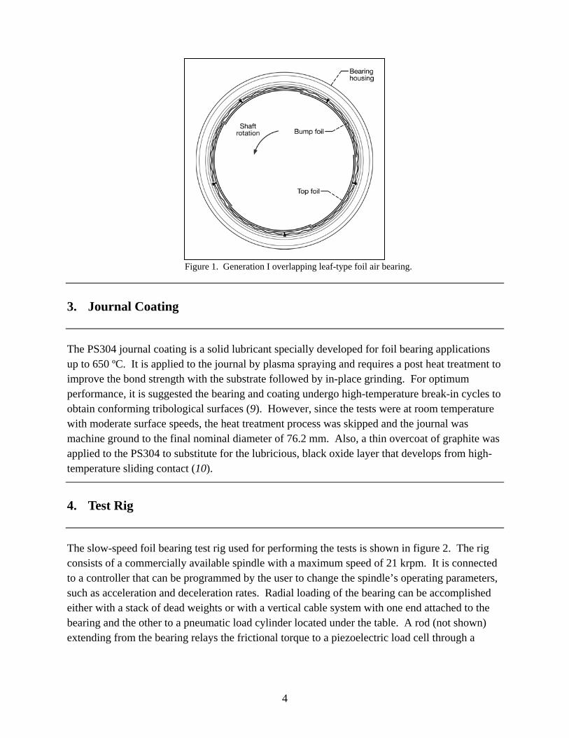
A cross-sectional view of the overlapping, leaf-type foil bearing used for testing is shown in figure 1. The bearing’s inside diameter (ID) was nominally 76.2 mm and its length was 88.9 mm. The bearing was constructed from five segmented foils in an overlapped arrangement around the entire circumference of the bearing. Each foil segment was coated with a soft polymer and supported by a bump foil. The bump foil was continuous across the bearing’s axial width, not split or in a staggered arrangement, putting it in the category of a Generation I bearing (8). The bearing was instrumented with three, type K thermocouples to monitor frictional heating during sliding contact. The thermocouples were secured on the lower curved portion of the bumps as near to the top foil as possible with high thermal conductive cement. Access to the bumps was provided by holes burned in the bearing’s shell by electro-discharge machining (EDM). The three thermocouples were in the same circumferential plane, with one hole located at the bearing’s center and one at each edge.
4
Figure 1. Generation I overlapping leaf-type foil air bearing.
3. Journal Coating
The PS304 journal coating is a solid lubricant specially developed for foil bearing applications up to 650 ºC. It is applied to the journal by plasma spraying and requires a post heat treatment to improve the bond strength with the substrate followed by in-place grinding. For optimum performance, it is suggested the bearing and coating undergo high-temperature break-in cycles to obtain conforming tribological surfaces (9). However, since the tests were at room temperature with moderate surface speeds, the heat treatment process was skipped and the journal was machine ground to the final nominal diameter of 76.2 mm. Also, a thin overcoat of graphite was applied to the PS304 to substitute for the lubricious, black oxide layer that develops from high-temperature sliding contact (10).
4. Test Rig
The slow-speed foil bearing test rig used for performing the tests is shown in figure 2. The rig consists of a commercially available spindle with a maximum speed of 21 krpm. It is connected to a controller that can be programmed by the user to change the spindle’s operating parameters, such as acceleration and deceleration rates. Radial loading of the bearing can be accomplished either with a stack of dead weights or with a vertical cable system with one end attached to the bearing and the other to a pneumatic load cylinder located under the table. A rod (not shown) extending from the bearing relays the frictional torque to a piezoelectric load cell through a
5
section of wire cable. A data acquisition system controls the motor and collects speed and temperature data.
Figure 2. Slow-speed foil bearing test rig.
5. Test Plan
The durability tests were performed in two separate phases, both at room temperature. The first phase consisted of subjecting the bearing and PS304 coating to 100 start-stop cycles while the bearing supported a load of 266.9 N. The spindle was programmed to accelerate at a rate of 500 rpm/s from 0 to 15 krpm, which is 400 rpm/s less than the ramp rate during start-up of a typical T700 engine, making for a more severe operating condition since the test will consist of a longer period of sliding contact. In the second phase of testing, the bearing and coating were placed under continuous sliding contact at 3 krpm for 10 min while the bearing supported 266.9 N to simulate wind milling of the engine. After both phases, the bearing and coating were inspected for signs of wear or damage.
6. Test Setup and Procedure
Setup for the 100 start-stop tests consisted of installing the PS304-coated journal on the spindle and performing dynamic balancing iterations to reach 15 krpm. After applying the graphite overcoat, the bearing was installed on the journal and the cable was placed between the rod and load cell to measure torque. Since the combined weight of the bearing and ancillary hardware was 22.3 N, an additional load of 244.6 N was applied. With the controller programmed for a 500 rpm/s ramp rate, the data acquisition system was turned on and power was delivered to the spindle. Since the spindle was unable to overcome the approximately 3.6 N-m of static frictional
6
torque produced by the load and bearing preload, the load was partially supported manually at the beginning of each test to initiate journal rotation. At the onset of rotation the load was immediately released to permit the bearing to fully support the load while the journal’s speed increased to 15 krpm, which took about 30 s. After a few seconds, power to the spindle was removed causing the journal to freely decelerate to rest, which took about 26 s. This spindle acceleration and deceleration constituted one start-stop test cycle. After completing cycles 5, 15, 25, 35, 50, 75, and 100 testing was stopped to inspect the bearing and PS304 coating for damage and wear.
Upon completion of the phase I tests, the bearing was placed back on the journal, the load re-applied, and the spindle programmed for a ramp rate of 1200 rpm/s. No additional graphite coating was applied. To begin the phase II test, the load was partially supported at startup then released as the spindle quickly accelerated to 3 krpm, which is about half of the bearing’s lift-off speed. This speed was held for 10 min while bearing temperature data was collected. At the test’s conclusion the bearing and PS304 coating were inspected for signs of damage and wear.
7. Discussion of Results
A full understanding of the test conditions required that two of the bearing’s main operating characteristics, its spring preload and lift-off speed, be known. The bearing’s preload was obtained by following the technique described in reference 7. Outlined there, the first step is to measure the break-away torque at various static loads with a torque wrench and then plot the data with torque as a function of load. When a linear least square fit is performed on the data, the resulting y-intercept is the preload contribution to the torque. Knowing the coefficient of friction the preload can then be calculated. As shown by the plot in figure 3, the bearing was loaded from 44.5 to 266.9 N in 44.5 N increments and the break-away torque measured. The curve fit indicates that the preload torque is approximately 1.48 N-m. Assuming the coefficient of friction between the soft polymer and PS304 is 0.20, the bearing preload was calculated to be 9.1 kPa.
7
y = 0.0077x + 1.4763
0.0
0.5
1.0
1.5
2.0
2.5
3.0
3.5
4.0
0 50 100 150 200 250 300
Radial Load, N
To
rqu
e,
N-m
0.0
4.4
8.8
13.1
17.5
21.9
26.3
30.6
35.0
To
rqu
e, i
n-l
bs
9.1kPa preload
Figure 3. Bearing break-away torque for loads from 44.5 to 266.9 N. The y-intercept represents the break-away torque caused by the preload in the bearing.
To determine the bearing’s lift-off speed at a load of 266.9 N, a large donut weighing 253.5 N was manufactured from a heavy tungsten alloy. As shown in figure 4, the bearing sat inside of the donut and the threaded rod extending from the donut transmitted the bearing torque to a load cell. Including the bearing and rod the final weight was a little over 266.9 N. By monitoring for a sharp increase in torque (signifying loss of the air film) during coast-down of a start-stop cycle, the bearing’s lift-off speed was found to be approximately 6 krpm.
A time history plot for start-stop interval 76–100 showing journal speed and bearing temperatures is shown in figure 5 and is representative of the data collected during the other intervals. The three upper curves are bearing temperatures and the lower saw-toothed curve is the speed profile of the journal. As seen in the plot, the bearing experienced a small, non-uniform increase in temperature from frictional heating due to sliding contact and viscous shear in the air film during the 25 start-stops.
8
Figure 4. Setup to determine the foil bearing’s lift-off speed while supporting 266.9 N.
0
3
6
9
12
15
18
21
24
27
30
0 200 400 600 800 1000 1200 1400 1600 1800 2000
Time, Seconds
Sp
eed
, k
rpm
0.0
5.5
11.0
16.5
22.0
27.5
33.0
38.5
44.0
49.5
55.0
Tem
per
atu
re,
ºC
Middle
Outboard
Inboard
Figure 5. Time history plot of start-stop interval 76–100.
At the start of the test the bearing’s bulk temperature was 24 ºC but increased to approximately 49 ºC at the middle and 41 ºC at the bearing edges. The close proximity in edge temperatures suggest that the load was evenly distributed across the bearing’s length. Also, the axial temperature distribution, with the maximum temperature in the middle, corroborates well with the findings in the literature (11).
The condition of the bearing and PS304 coating after 100 start-stops is shown in figures 6 and 7, respectively. As shown in figure 6, the loss of the soft polymer from the top foils occurred in a tiger striped pattern around the circumference of the bearing. In fact, removal of the polymer was first seen in the high load region after only 5 start-stop cycles, indicating that the remaining 95 cycles were performed with the foil substrate in direct contact with the PS304 coating. As the testing progressed, the coating continued to be removed from other parts of the bearing exposing more of the foil substrate to the PS304 coating. Visual inspection of the PS304 after the predetermined set of cycles did not uncover any wear or damage to the coating except for a few
9
areas of fine surface polishing. Measurements with a micrometer confirmed the absence of any diametric changes in the PS304 coating.
Figure 6. Bearing after 100 start-stop cycles showing removal of soft polymer from top foils.
Figure 7. PS304 coated journal after 100 start-stop cycles. No spallation or delamination is evident.
A plot of the temperature results from the simulated wind milling test is shown in figure 8. The test was performed with a 266.9 N load and 3 krpm journal speed, which is half of the bearing’s lift-off speed. Therefore, the PS304 coating was in direct sliding contact with the bearing’s top foils throughout the entire test. Again, the frictional heating caused a small, non-uniform increase in the bearing’s temperature after sliding for 10 min, which suggests that thermal loading under this condition is not a concern. At the beginning of the test the bearing’s bulk temperature was 82 °F, but at the test’s conclusion the temperatures were approaching steady-
10
state with the middle at 110 °F, the inboard edge at 105 °F, and the outboard edge at 101 °F. A more accurate representation of operating conditions after an in-flight shutdown would be to perform some of the tests at higher temperatures since the engine would be hot from running. However, testing at room temperature represents a worst-case scenario since PS304 has demonstrated excellent wear resistance at high temperatures but its performance degrades as the temperature drops. The bearing’s structural integrity remained intact and a comparison between figures 6 and 9 indicates that any additional amount of coating removal from the top foils was small. As seen in figure 10, the PS304 coating did not experience any wear, delamination, or spallation. Measurements with a micrometer corroborate the lack of any diametric changes.
0
5
10
15
20
25
30
35
40
45
50
0 100 200 300 400 500 600 700 800
Time, seconds
Te
mp
era
ture
, ºC
Middle
Inboard
Outboar
Figure 8. Bearing temperature profile during operation at 3 krpm while supporting 266.9 N for 10 min.
Figure 9. Condition of top foils after continuous sliding test.
11
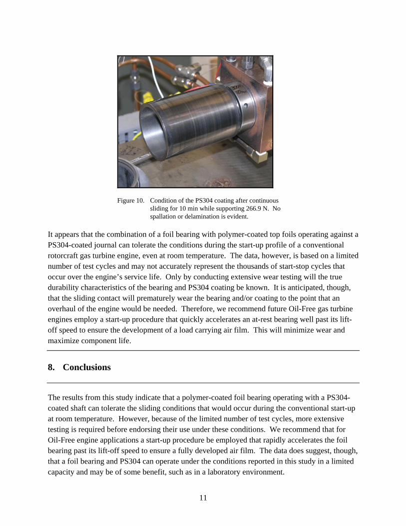
Figure 10. Condition of the PS304 coating after continuous sliding for 10 min while supporting 266.9 N. No spallation or delamination is evident.
It appears that the combination of a foil bearing with polymer-coated top foils operating against a PS304-coated journal can tolerate the conditions during the start-up profile of a conventional rotorcraft gas turbine engine, even at room temperature. The data, however, is based on a limited number of test cycles and may not accurately represent the thousands of start-stop cycles that occur over the engine’s service life. Only by conducting extensive wear testing will the true durability characteristics of the bearing and PS304 coating be known. It is anticipated, though, that the sliding contact will prematurely wear the bearing and/or coating to the point that an overhaul of the engine would be needed. Therefore, we recommend future Oil-Free gas turbine engines employ a start-up procedure that quickly accelerates an at-rest bearing well past its lift-off speed to ensure the development of a load carrying air film. This will minimize wear and maximize component life.
8. Conclusions
The results from this study indicate that a polymer-coated foil bearing operating with a PS304-coated shaft can tolerate the sliding conditions that would occur during the conventional start-up at room temperature. However, because of the limited number of test cycles, more extensive testing is required before endorsing their use under these conditions. We recommend that for Oil-Free engine applications a start-up procedure be employed that rapidly accelerates the foil bearing past its lift-off speed to ensure a fully developed air film. The data does suggest, though, that a foil bearing and PS304 can operate under the conditions reported in this study in a limited capacity and may be of some benefit, such as in a laboratory environment.
12
9. References
1. Emerson, T. P. The Application of Foil Air Bearing Turbomachinery in Aircraft Environmental Control Systems. Proc. of the ASME Intersociety Conference on Environ-mental Systems, San Diego, CA, Paper No. 780-ENAS-18, 1978.
2. Agrawal, G. L. Foil Gas Bearings for Turbomachinery. Proc. of 20th Intersociety Conference on Environmental Systems, Williamsburg, VA. SAE Paper No. 901236.
3. Lubell, D.; DellaCorte, C.; Stanford, M. K. Test Evolution and Oil-Free Engine Experience of a High Temperature Foil Air Bearing Coating. Proc. of GT2006: ASME Turbo Expo 2006, Barcelona, Spain, GT2006-90572, 2006.
4. Valco, M. J.; DellaCorte, C. Oil-Free Turbomachinery Technology for Regional Jet, Rotorcraft and Supersonic Business Jet Propulsion Engines. 16th International Symposium on Air Breathing Engines, Cleveland, OH, Aug. 31–Sept. 5, 2003.
5. DellaCorte, C. The Evaluation of a Modified Chrome Oxide Based High Temperature Solid Lubricant Coating for Foil Gas Bearings; NASA-TM-1998-20860; 1998.
6. Howard, S. A.; Bruckner, R.; DellaCorte, C.; Radil, K. C. Preliminary Analysis for an Optimized Oil-Free Rotorcraft Engine Concept; NASA/TM 2008-215064; 2008.
7. DellaCorte, C.; Lukaszewicz, V.; Valco, M. J.; Radil, K. C.; Heshmat, H. Performance and Durability of High Temperature Foil Air Bearings for Oil-Free Turbomachinery. NASA TM-2000-209187; 1999.
8. DellaCorte, C.; Valco, M. J. Load Capacity Estimation of Foil Air Journal Bearings for Oil-Free Turbomachinery Applications. STLE Tribology Transactions 2000, 43 (4), 795–801.
9. Radil, K. C.; DellaCorte, C. The Effect of Journal Roughness and Foil Coatings on the Performance of Heavily Loaded Foil Air Bearings; NASA TM-2001-210941; 2001.
10. DellaCorte, C.; Zaldana, A. R.; Radil, K. C. A Systems Approach to the Solid Lubrication of Foil Air Bearings for Oil-Free Turbomachinery ASME J. of Trib. 2004, 126, 200-207.
11. Radil, K.; Zeszotek, M. An Experimental Investigation into the Temperature Profile of a Compliant Foil Air Bearing. STLE Tribology. 2003, 46 (4).
13
NO. OF COPIES ORGANIZATION 1 ADMNSTR PDF DEFNS TECHL INFO CTR ATTN DTIC OCP 8725 JOHN J KINGMAN RD STE 0944 FT BELVOIR VA 22060-6218 1 HC DARPA ATTN IXO S WELBY 3701 N FAIRFAX DR ARLINGTON VA 22203-1714 1 CD OFC OF THE SECY OF DEFNS ATTN ODDRE (R&AT) THE PENTAGON WASHINGTON DC 20301-3080 1 HC US ARMY RSRCH DEV AND ENGRG CMND ARMAMENT RSRCH DEV AND ENGRG CTR ARMAMENT ENGRG AND TECHNLGY CTR ATTN AMSRD AAR AEF T J MATTS BLDG 305 ABERDEEN PROVING GROUND MD 21005-5001 20 HCs NASA GLENN RSRCH
ATTN RDRL VTP K RADIL (20 HCS)
MS 23-2 21000 BROOKPARK RD CLEVELAND OH 44135 1 HC PM TIMS, PROFILER (MMS-P) AN/TMQ-52 ATTN B GRIFFIES BUILDING 563 FT MONMOUTH NJ 07703 1 HC US ARMY INFO SYS ENGRG CMND ATTN AMSEL IE TD A RIVERA FT HUACHUCA AZ 85613-5300 1 HC COMMANDER US ARMY RDECOM ATTN AMSRD AMR W C MCCORKLE 5400 FOWLER RD REDSTONE ARSENAL AL 35898-5000
NO. OF COPIES ORGANIZATION 1 HC US GOVERNMENT PRINT OFF DEPOSITORY RECEIVING SECTION ATTN MAIL STOP IDAD J TATE 732 NORTH CAPITOL ST NW WASHINGTON DC 20402 1 HC US ARMY RSRCH LAB ATTN RDRL CIM G TECHL LIB T LANDFRIED BLDG 4600 ABERDEEN PROVING GROUND MD 21005-5066 3 HCS US ARMY RSRCH LAB ATTN RDRL CIM P TECHL PUB ATTN RDRL CIM L TECHL LIB ATTN IMNE ALC HRR MAIL & RECORDS MGMT ADELPHI MD 20783-1197