12
FOLDING DOOR ASSEMBLY AND MAINTENANCE MANUAL Rev.: 11.2005 AUTOMATIC DOORS FOR LIFTS ACMAP1 *ACMAP1* INS-TEC-GC-40.02 V1

FOLDING DOOR ASSEMBLY AND MAINTENANCE MANUAL
Rev.: 11.2005
AUTOMATIC DOORS FOR LIFTS
ACMAP1*ACMAP1* INS-TEC-GC-40.02 V1
AUTOMATIC DOORS FOR LIFTS
FOLDING DOORS2
INDEX
PACKAGING CONTENT .................................................................................3
TECHNICAL DRAWING .................................................................................3
OPERATOR ASSEMBLY INTO THE CABIN DOOR .............................................4
SILL ASSEMBLY ..........................................................................................4
PANEL ASSEMBLY .......................................................................................4
PANEL CLOSING ADJUSTMENT. ...................................................................5
FINISHING CONTACTS ADJUSTMENT ...........................................................5
ELECTRICAL AND WIRES DIAGRAM (WITH C4T CIRCUIT) ..............................6
ELECTRICAL AND WIRES DIAGRAM ..............................................................8
LANDING DOOR COUPLING ..........................................................................9
TECHNICAL SUPPORT ...............................................................................10
NECESSARY TOOLS ...................................................................................11
DECLARATION OF CONFORMITY .................................................................11
FOLDING DOORS 3
AUTOMATIC DOORS FOR LIFTS
= =
100
1167
27
200
70100 *
6
100
6
10021
100
62
120
6
2525
158
21
550
*
20
2525
1
2
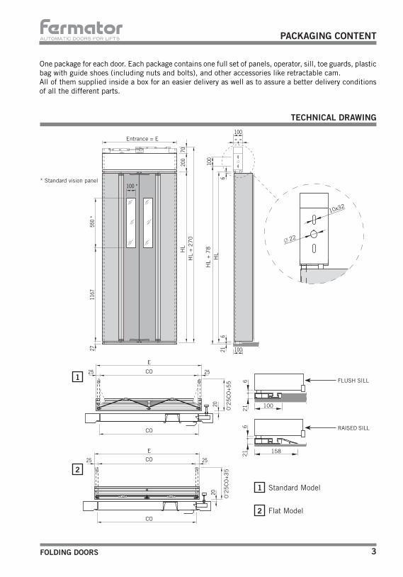
One package for each door. Each package contains one full set of panels, operator, sill, toe guards, plastic bag with guide shoes (including nuts and bolts), and other accessories like retractable cam.All of them supplied inside a box for an easier delivery as well as to assure a better delivery conditions of all the different parts.
2
1 Standard Model
Flat Model
PACKAGING CONTENT
TECHNICAL DRAWING
* Standard vision panel
Entrance = E
E
E
CO
CO
HL
+ 7
8
HL
+ 2
70
HL
HL
CO
CO
FLUSH SILL
RAISED SILL
0’2
5C
O+5
50
’25
CO
+3
5
22
10x32

AUTOMATIC DOORS FOR LIFTS
FOLDING DOORS4
PANEL ASSEMBLY
Remove the elastic rings that fix the moving shaft to the operator and move it 20mm upwards.
Put the vertical shaft of the panel in the sill sleeve.
Push down the moving shaft, putting it in the panel vertical shaft, checking the alignment of both millings.
Place again the fixation rings of the lateral shaft on the operator.
Put back the elastic rings. Verify that supports and guides move freely in both aluminium rails.
OPERATOR ASSEMBLY INTO THE CABIN DOOR
Drill four holes (10,25mm.) in the entrance door posts and fix, with four screws, the operator to the door posts using the slots of the operator side cartouches.Place the operator centred with the cabin and at the right height from the floor. If the drills are made centred, this will allow a regulation of (+/-)10mm.Verify that the side arms free the cabin door posts in the upper side of the operator, if this does not happen, cut the door posts until they are at 5mm of the operator upper base.
SILL ASSEMBLY
Check the vertical alignment with the operator. Drill three holes in the cabin floor which will coincide with the position of the screw holes in the sill rails. It is recommended to drill four big enough holes in the sill rails, coinciding with those in the sill to evacuate any waste.
12
66
21
100 158
21
6
21
6FLUSH SILL RAISED SILL
Elastic ring
Lateral shaft
Panels
Sill Sleeve
Supportsand
guides
FOLDING DOORS 5
AUTOMATIC DOORS FOR LIFTS
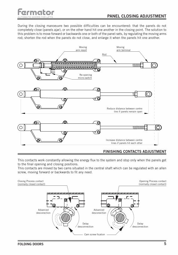
During the closing manoeuvre two possible difficulties can be encountered: that the panels do not completely close (panels ajar), or on the other hand hit one another in the closing point. The solution to this problem is to move forward or backwards one or both of the panel-sets, by regulating the moving arms rod; shorten the rod when the panels do not close, and enlarge it when the panels hit one another.
This contacts work constantly allowing the energy flux to the system and stop only when the panels get to the final opening and closing positions. This contacts are moved by two cams situated in the central shaft which can be regulated with an allen screw, moving forward or backwards to fit any need.
PANEL CLOSING ADJUSTMENT
Movingarm resort
Movingarm terminal
Rod
Re-opening micro-switch
Reduce distance between centre line if panels remain open
Increase distance between centre lines if panels hit each other
FINISHING CONTACTS ADJUSTMENT
Closing Process contact(normally closed contact)
Opening Process contact(normally closed contact)
Advanceddesconection
Delaydesconnection
Cam screw fication
Advanceddesconection
Delaydesconnection
AUTOMATIC DOORS FOR LIFTS
FOLDING DOORS6
SW1 SW2
F1
IC1
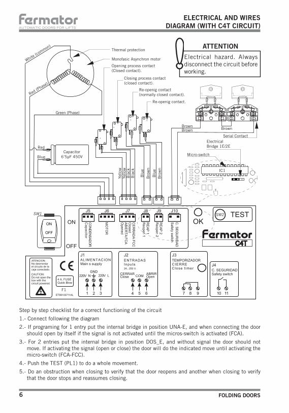
Step by step checklist for a correct functioning of the circuit
1.- Connect following the diagram
2.- If programing for 1 entry put the internal bridge in position UNA-E, and when connecting the door should open by itself if the signal is not activated until the micros-switch is activated (FCA).
3.- For 2 entries put the internal bridge in position DOS_E, and without signal the door should not move. If activating the signal (open or close) the door will do the indicated move until activating the micro-switch (FCA-FCC).
4.- Push the TEST (PL1) to do a whole movement.
5.- Do an obstruction when closing to verify that the door reopens and another when closing to verify that the door stops and reassumes closing.
ELECTRICAL AND WIRESDIAGRAM (WITH C4T CIRCUIT)
Monofasic Asynchron motorWhite (co
mmon)Thermal protection
Red (Phase
)
Green (Phase)
Capacitor6’5µF 450V
Red
Blue
Brown
Serial Contact
Opening process contact (Closed contact).
Closing process contact (closed contact).
Re-openig contact (normally closed contact).
Re-openig contact.
Blu
e
Bro
wn
Bro
wn
Bla
ckB
lack
Yello
wYe
llow
ATTENTION
Electrical hazard. Always disconnect the circuit before working.
Brown
Blu
e
Brown
ElectricalBridge 1E/2E
Micro-switch
FOLDING DOORS 7
AUTOMATIC DOORS FOR LIFTS
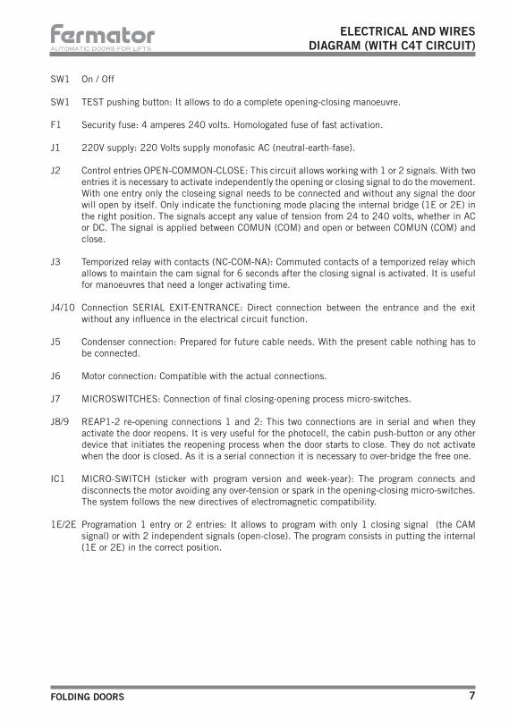
SW1 On / Off
SW1 TEST pushing button: It allows to do a complete opening-closing manoeuvre.
F1 Security fuse: 4 amperes 240 volts. Homologated fuse of fast activation.
J1 220V supply: 220 Volts supply monofasic AC (neutral-earth-fase).
J2 Control entries OPEN-COMMON-CLOSE: This circuit allows working with 1 or 2 signals. With two entries it is necessary to activate independently the opening or closing signal to do the movement. With one entry only the closeing signal needs to be connected and without any signal the door will open by itself. Only indicate the functioning mode placing the internal bridge (1E or 2E) in the right position. The signals accept any value of tension from 24 to 240 volts, whether in AC or DC. The signal is applied between COMUN (COM) and open or between COMUN (COM) and close.
J3 Temporized relay with contacts (NC-COM-NA): Commuted contacts of a temporized relay which allows to maintain the cam signal for 6 seconds after the closing signal is activated. It is useful for manoeuvres that need a longer activating time.
J4/10 Connection SERIAL EXIT-ENTRANCE: Direct connection between the entrance and the exit without any influence in the electrical circuit function.
J5 Condenser connection: Prepared for future cable needs. With the present cable nothing has to be connected.
J6 Motor connection: Compatible with the actual connections.
J7 MICROSWITCHES: Connection of final closing-opening process micro-switches.
J8/9 REAP1-2 re-opening connections 1 and 2: This two connections are in serial and when they activate the door reopens. It is very useful for the photocell, the cabin push-button or any other device that initiates the reopening process when the door starts to close. They do not activate when the door is closed. As it is a serial connection it is necessary to over-bridge the free one.
IC1 MICRO-SWITCH (sticker with program version and week-year): The program connects and disconnects the motor avoiding any over-tension or spark in the opening-closing micro-switches. The system follows the new directives of electromagnetic compatibility.
1E/2E Programation 1 entry or 2 entries: It allows to program with only 1 closing signal (the CAM signal) or with 2 independent signals (open-close). The program consists in putting the internal (1E or 2E) in the correct position.
ELECTRICAL AND WIRESDIAGRAM (WITH C4T CIRCUIT)

AUTOMATIC DOORS FOR LIFTS
FOLDING DOORS8
ATTENTION
Electrical hazard. Always disconnect the circuit before working.
ELECTRICAL AND WIRES DIAGRAM
White (common II or Phase III)AC II or III ASINC. MOTOR
Green - Yellow
Red (Phase)Green (P
hase)
Brown
Re-opening contact (closed contact)
Closing process contact (closed contact)
Opening process contact (closed contact)
Yello
w
Bla
ck
Blu
e
Motor FCA FCC Reop. Serial
Blu
e
Bla
ck
Yello
w
Serial Contact
Capacitor6’5µF 450V
White
Brown
Brown
1
This is the suitable connection to be able to work with the NC contacts (normally closed) of the reopening microswitches.
To be able to work with NA terminals (normally opened) the connection must be in parallel as shown in the picture.
1
Blu
e
Blu
e
Bro
wn
Brown
Only II Motor

FOLDING DOORS 9
AUTOMATIC DOORS FOR LIFTS
SEMIAUTOMATICLANDING DOOR OPEN SYSTEM
Place the retractive cam in the cabin door. With the door closed, the cam will remain folded. (fig. 1) When the door is open, the cam remains unfolded actioning the roller in the landing lock. (fig. 2)
Fig. 1
Fig. 2
OPEN SYSTEM WITH RETRACTABLE CAM (FRONTAL ACTING)
Fig. 1
Fig. 2
OPEN SYSTEM WITH RETRACTABLE CAM (SIDE ACTING)
45 10
7520
2248
25
7520
2248 10
0
80
25
PL
PL
100
35
32
5
32
70
50
20
5045
(± 1
1)
100
10
5
45
70
50PL 25
755
5050
35
PL 25
2010
020
100
45
75

AUTOMATIC DOORS FOR LIFTS
FOLDING DOORS10
TECHNICAL SUPPORT
FAILURE POSSIBLE CAUSE SOLUTION- The operator does not open or
close, it remains stoped.- The electrical supply does not
reach the motor.- Check entering tension in the
connection terminals.
- There is supply but the motor does not open or close.
- Broken trapezoidal belt.
- Broken cogged be it.
- Motor pulley too lose.
- Reduction pulley not blocked.
- Replace trapezoidal belt and adjust tension.
- Replace the cogged be it.
- Tighten the motor pulley.
- Change the pulley and check the malling.
- The operator works but the panels do not move.
- The moving shafts do not move the panels.
- The shaft does not gear into the panels.
-Blocked panels.
- Trapezoidal belt too tight.
- Check the position of the moving shaft over the panel.
- Move down the operator until the shaft enters completely in the moving panel shaft.
- Unlock the panels and inspection rails.
-Untighten the motor screws until the belt is correctly tensed.
- The door opens but does not close.
- Re-opening contact actioned (Open).
- Re-opening contact opposed to what is indicted.
- Blocked actioning arm.
- No cam signal.
- No motor disconnection.
- Adjust the re-opening micro-switch.
- Change the contact terminal connection (third cable).
- Disseamble the arm and check the internal.
- Check the entering signal parallel to the existing cam.
- Adjust the cam that actions the closing final micro-switch.
- The operator motor does not disconnect.
- Wrong adjustment of the closing final micro-swich.
- Adjust the cams that activate the micro-switch.
- The re-opening works constantly. - Obstruction in the cabin door threeshold.
- Re-opening spring loose.
- The panels get blocked during the closing process.
- Retire the obstruction and cleand the sill.
- Change the spring.
- Clean the grease the sleeves and hinges.
- The door operator does some kind of noise.
- The sleeves in both shaft need grease or oil.
- Oil or grease, never with spray.
- There is an electrical fault on the signal of the panels presence.
- There is no continuity in any of the two serial contacts.
- Check whether the contact is working properly centred with no carbon deposit or dirt.
- The panels do not close or open completly.
- The central shaft does not rotate 180º.
- Adjust the arm following the explanations in pag. 5.
- Move backwards the cams that action the micro-switches.

FOLDING DOORS 11
AUTOMATIC DOORS FOR LIFTS
Keys for hexagonal screws: 6/7 (x2) - 8/9 (x2) - 10/11 (x2) - 12/13 (x2)
Keys for Allen screws: 2,5 - 3
Screwdrivers: 1 and 1 Phillips screwdriver
Electric drill with drills of: 6,25 - 8,25
Nylon Hammer.
Spirit level
Pliers with drills tip for elastic rings.
NECESSARY TOOLS
Tecnolama, S.A.Ctra. Constantí Km. 343206 REUS (Spain)
Herewith declares that the products mentioned below conform with the following E.U. council directives:
Tecnolama S.A., 2007
Josep Vilà GomisAdministrator
E.U. council directive of electromagnetic compatibility and immunity 89/336-CEE, conform with Norms EN12015 and EN12016,
about lift doors:
Manoeuvre system for lift doors 40/10 mechanical model(EMI-370)
DECLARATION OF CONFORMITY

ATENTION: Any type of modification not reflexed in this manual, before testing it should be notified to our Tecnichal Department.TECNOLAMA declines all responsability in the case of damages produced in the operator and installation, if the instructions given have not been followed.TECNOLAMA reserves the rights to modify the products specifications of this technical brochure without any previous advise.
Ctra. Constantí, Km 3 - 43206 REUS (Spain) - Tel. +34 977 774 065 - Fax +34 977 771 615 h t t p : / / w w w . f e r m a t o r . c o m e - m a i l : c o m e r c i a l @ f e r m a t o r . c o m


