40
Food & Beverage Cabinet
Food & Beverage Cabinet

Part No. 22958 Rev. P June 2017 - 2 - Fusion, Food & Beverage Cabinet
Copyright © June 2017 Future Products Group Limited. All rights reserved.
No part of this publication may be reproduced, stored in a retrieval system, or transmitted in any form or by any means, electronic, mechanical, photocopying, recording or otherwise, without the prior written permission of Future Products Group Ltd.

IN-FUS-HC10 - 3 - © Future Products Group
Table of Contents
INTRODUCTION ................................................................................................................. 7
Welcome ........................................................................................................................................................... 7
Future Products Group (FPG) .................................................................................................................... 7 Guidance and Help ..................................................................................................................................... 7
Warranty ........................................................................................................................................................... 7
Warranty Period .......................................................................................................................................... 7 Liability Exceptions ..................................................................................................................................... 8 Specific Exclusions ..................................................................................................................................... 8 Assessment ................................................................................................................................................ 8 Time Limit ................................................................................................................................................... 8 Caution ....................................................................................................................................................... 8
OPERATION ....................................................................................................................... 9
Cabinet Layout ................................................................................................................................................. 9
Fusion Series Cabinets .............................................................................................................................. 9 Lighting ....................................................................................................................................................... 9 Refrigeration Equipment ............................................................................................................................. 9 Heated Section ........................................................................................................................................... 9 Thermometers ............................................................................................................................................ 9
Controls .......................................................................................................................................................... 10
Mains Power ............................................................................................................................................. 10 Refrigerated Section Controls .................................................................................................................. 10 Heated Section Controls .......................................................................................................................... 10
Preparation ..................................................................................................................................................... 11
Power Supply ........................................................................................................................................... 11 Heating ..................................................................................................................................................... 11 Refrigeration ............................................................................................................................................. 11 Defrost Cycle ............................................................................................................................................ 11 Load Cabinet ............................................................................................................................................ 11 Shelves Positions ..................................................................................................................................... 11 Shelf Loading ............................................................................................................................................ 11
Operational Routines .................................................................................................................................... 12
After Hours ............................................................................................................................................... 12 Cleaning ................................................................................................................................................... 12 Refrigeration Condensate ........................................................................................................................ 12 Warning- Flammable Products ................................................................................................................. 12
Equipment Disposal ...................................................................................................................................... 12
Specialist Disposal ................................................................................................................................... 12
TROUBLE SHOOTING ..................................................................................................... 13
Dixell XR40CX Alarm Responses ................................................................................................................. 14
Probe Faults ............................................................................................................................................. 14 HA Alarm .................................................................................................................................................. 14 HA2 Alarm ................................................................................................................................................ 14

Part No. 22958 Rev. P June 2017 - 4 - Fusion, Food & Beverage Cabinet
CLEANING ........................................................................................................................ 15
Cautions ......................................................................................................................................................... 15
Power ....................................................................................................................................................... 15 Water ........................................................................................................................................................ 15
Exterior ........................................................................................................................................................... 15
Painted and Metal Surfaces ..................................................................................................................... 15
Interior............................................................................................................................................................. 15
Condensate Tray ...................................................................................................................................... 15 Shelves & Trays ....................................................................................................................................... 15 Cabinet Well ............................................................................................................................................. 16 Cooling Fins .............................................................................................................................................. 16 Temperature Probe .................................................................................................................................. 16 Drain Holes ............................................................................................................................................... 16
Routines ......................................................................................................................................................... 17
Schedules ................................................................................................................................................. 17 Condenser Radiator ................................................................................................................................. 17 ACR Tray .................................................................................................................................................. 17 Warning .................................................................................................................................................... 17 Inspection ................................................................................................................................................. 17 Correction ................................................................................................................................................. 17
INSTALLATION ................................................................................................................ 18
Regulations .................................................................................................................................................... 18
Compliance with Local Requirements ...................................................................................................... 18 Operational Safety .................................................................................................................................... 18
Preparation ..................................................................................................................................................... 18
Unpacking ................................................................................................................................................. 18 Cabinet Preparation.................................................................................................................................. 18 Power Supply ........................................................................................................................................... 18 Earthing .................................................................................................................................................... 18 Equipotential Bonding .............................................................................................................................. 18
Location .......................................................................................................................................................... 19
Ventilation ................................................................................................................................................. 19 Access ...................................................................................................................................................... 19 Draughts ................................................................................................................................................... 19 Level Site .................................................................................................................................................. 19

IN-FUS-HC10 - 5 - © Future Products Group
SERVICING ....................................................................................................................... 20
Mains Lead ..................................................................................................................................................... 20
Lead Replacement ................................................................................................................................... 20
Lighting ........................................................................................................................................................... 20
Protection ................................................................................................................................................. 20 Caution ..................................................................................................................................................... 20 LED Strips ................................................................................................................................................ 20 LED Power Supplies................................................................................................................................. 20
Heating ............................................................................................................................................................ 21
Heating Elements ..................................................................................................................................... 21 Element Replacement .............................................................................................................................. 21 Temperature Control ................................................................................................................................ 21 Thermometer Battery Replacement ......................................................................................................... 21 Control Gear ............................................................................................................................................. 22 Ventilation Fan .......................................................................................................................................... 22
Refrigeration .................................................................................................................................................. 22
Caution ..................................................................................................................................................... 22 Access to Control Gear etc. ..................................................................................................................... 22 Access to Condensing Unit etc. ............................................................................................................... 23 Condenser Ventilation .............................................................................................................................. 23 Controller Adjustment ............................................................................................................................... 23 Probe Locations ........................................................................................................................................ 24 Thermometer ............................................................................................................................................ 24 Fan Deck .................................................................................................................................................. 24 Condensate Disposal ............................................................................................................................... 25 ACR Fault Finding Guide ......................................................................................................................... 25 Temperature Regulator XR40CX ............................................................................................................. 26 XR40CX Compressor Control .................................................................................................................. 26 XR40CX Defrost Control .......................................................................................................................... 26 XR40CX Key Functions ............................................................................................................................ 27 XR40CX LED Functions ........................................................................................................................... 27 XR40CX Min & Max Recorded Temperature .......................................................................................... 28 XR40CX Reset Max/Min Temperature Memory ...................................................................................... 28 XR40CX Display the Set-point ................................................................................................................. 28 XR40CX Change the Set-point ................................................................................................................ 28 XR40CX Start a Manual Defrost ............................................................................................................. 28 XR40CX Programming Mode ................................................................................................................... 28 XR40CX The Hidden Menu ...................................................................................................................... 29 XR40CX Locking and Unlocking the Keyboard ........................................................................................ 29 FPG Settings ............................................................................................................................................ 30 XR40CX Hot Key ..................................................................................................................................... 31 XR40CX Alarm Signals ............................................................................................................................ 32 XR40CX Alarm Recovery ......................................................................................................................... 32 XR40CX Other Messages ........................................................................................................................ 32 XR40CX Connections .............................................................................................................................. 32

Part No. 22958 Rev. P June 2017 - 6 - Fusion, Food & Beverage Cabinet
SPECIFICATIONS ............................................................................................................. 33
Mechanical ..................................................................................................................................................... 33
Electrical ......................................................................................................................................................... 33
Cabinet Performance ..................................................................................................................................... 34
Refrigerated Section Performance ........................................................................................................... 34
Controller Settings ........................................................................................................................................ 34
Application Specific Settings .................................................................................................................... 34 XR40CX Settings...................................................................................................................................... 34
Compliance .................................................................................................................................................... 35
Safety Aspects .......................................................................................................................................... 35 Hazardous Substances ............................................................................................................................ 35
Improvements ................................................................................................................................................ 35
On-going Development ............................................................................................................................ 35
ELECTRICAL CIRCUIT DIAGRAM .................................................................................. 36
Model: IN-FUS-HC10-A004 ...................................................................................................................... 36
SPARE PARTS ................................................................................................................. 37
Cabinet Serial Number ............................................................................................................................. 37
MECHANICAL DRAWINGS .............................................................................................. 38
IN-FUS-HC10-A004.................................................................................................................................. 38

IN-FUS-HC10 - 7 - © Future Products Group
INTRODUCTION
Welcome COMBINED FOOD & BEVERAGE CABINETS - INTRODUCTION
Future Products Group (FPG)
Welcome to the world of FPG! Our products are designed and engineered to give you the optimal performance that you deserve with innovative visual merchandising appeal. We are confident that you will be delighted with your state of the art door-less bottle cooler, and that it will become a valued appliance in your store.
Guidance and Help
Any new appliance can seem very complex and confusing at first glance. To ensure you receive the utmost benefit from your new door-less bottle cooler, there are two things you can do.
Before operating the cabinet, please read the instruction book carefully and follow its recommendations. The time taken will be well spent. These instructions both general and technical tell you how to operate and look after your door-less bottle cooler so that you can receive the full benefits that this cabinet has to offer.
These instructions cannot, however, cover all eventualities. If you are unsure of any aspect of the installation, instructions or performance of your cabinet, contact your dealer promptly or contact us via email to [email protected].
Warranty COMBINED FOOD & BEVERAGE CABINETS - INTRODUCTION
Warranty Period
Future Products Group Limited warrants, to the original purchaser of an FPG manufactured door-less bottle cooler that for ONE YEAR (12 months), from the date of purchase, any defect in workmanship or material resulting in the product malfunctioning while under correct use will be rectified.
Liability under this warranty is limited to replacing or repairing a part, without charge.
Continued on next page

Part No. 22958 Rev. P June 2017 - 8 - Fusion, Food & Beverage Cabinet
Warranty cont. COMBINED FOOD & BEVERAGE CABINETS - INTRODUCTION
Liability Exceptions
Liability under this warranty does not include:
Any loss, or damage or expenses directly or indirectly arising from use or inability to use the product or from any other cause.
Any part of the cabinet which has been subject to misuse, neglect, alteration, incorrect installation, accident, or damage caused by transportation, use of abrasive chemicals, flooding, fire or acts of God.
Damage, resulting from failure to have the cabinet regularly serviced every three months by a refrigeration engineer. NB: You will be required to provide copies of service records in the event of compressor failure.
Any damage or malfunction resulting from the use of non-FPG supplied spare parts.
Specific Exclusions
The following are specifically excluded from warranty:
Breakage of glass or plastic components or the replacement of LED lighting strips or gaskets.
Maladjustment of the electronic refrigeration controller, by an unqualified person.
Routine compressor / radiator cleaning.
Failure to re-assemble the cabinet correctly after cleaning.
Fair wear and tear.
Assessment The liability under this warranty is dependent on an assessment by FPG, to
determine the defect in workmanship or materials.
Time Limit FPG does not guarantee that any service to be performed under this warranty
will be carried out within any particular time limit.
Caution No warranty claim will be accepted unless authorised by FPG prior to
commencement of service.

IN-FUS-HC10 - 9 - © Future Products Group
OPERATION
Cabinet Layout COMBINED FOOD & BEVERAGE CABINETS - OPERATION
Fusion Series Cabinets
The Fusion Series cabinets are open fronted with closed backs.
The upper section of the cabinet is heated and the lower section is refrigerated.
Although the combined cabinet is constructed as a single unit, each half is electrically independent, with its own power supply cable and plug.
Lighting Each half of the cabinet is fitted with high efficiency LED lighting as standard.
The lighting in the cold section is independently controlled, but the lighting in the heated section is on when the heating is turned on.
Refrigeration Equipment
The refrigeration equipment is located in the base of the cabinet.
The cabinet has openings to allow adequate ventilation to ensure efficient performance.
Articles which could restrict air flow must NOT be placed against the cabinet.
Heated Section Heat is provided by radiant elements,
above the shelves, and the lower shelf is directly heated.
The control for the heated section is on the back of the cabinet.
A fan circulates air to cool the pelmet, and this must not be obstructed.
Thermometers Thermometers are located on the left side, below the heated section and below
the return-air grill of the refrigerated section.
These indicate the operating temperatures of the heated and refrigerated sections of the cabinet.

Part No. 22958 Rev. P June 2017 - 10 - Fusion, Food & Beverage Cabinet
Controls COMBINED FOOD & BEVERAGE CABINETS - OPERATION
Mains Power Mains power is independently supplied to each section of the cabinet.
The upper heated section has a readily accessible mains switch on the left of the pelmet, which controls both heating and lighting.
The refrigerated section has a safety mains isolation switch behind the front louver panel, but will normally be controlled from the supply socket. The air circulation and condenser fans will operate as soon as the power is turned on, but there is a separate switch for the lights, on the left of the upper shelf space.
Refrigerated Section Controls
Apart from the light switch, there are no operator control switches on the refrigerated section. It is fully operational as soon as it is connected to a
mains power point. The control gear is located in the base of the cabinet.
The controller has indicator displays and programming buttons.
A safety mains isolator switch is provided for servicing.
A miniature circuit breaker protects the lighting and low power devices against overload.
Heated Section Controls
The mains switch controls both heating and lighting.
The thermostat for the heated section is on the back of the cabinet.

IN-FUS-HC10 - 11 - © Future Products Group
Preparation COMBINED FOOD & BEVERAGE CABINETS - OPERATION
Power Supply Ensure that power is connected to both cabinet sections.
Heating Use the power switch on the front left of the cabinet to turn on the heating.
The lighting in this section will come on whenever the heating is on.
Refrigeration The compressor and cabinet fans will run as soon as power is connected.
Use the light switch to control the illumination of the refrigerated section.
As the compressor runs, the cabinet temperature will begin to fall.
The temperature controller is pre-set to maintain products in a chilled state, and should not need adjustment.
Defrost Cycle The refrigeration system will automatically defrost periodically. By sensing the
temperature of the cooling fins, the timing and duration of the defrost periods is optimised and has minimal effect on product temperature.
Load Cabinet
When the appropriate section has reached its operating temperature, load the cabinet with pre-heated and pre-chilled product.
Hot products must be pre-heated before loading.
Shelves Positions
The shelf positions are factory set to achieve correct temperature distribution.
Consult FPG if product sizes require shelves to be moved.
Ticketing can be inserted along the front of each shelf.
Shelf Loading The maximum loading of any shelf must not exceed 15kg of evenly
distributed products.

Part No. 22958 Rev. P June 2017 - 12 - Fusion, Food & Beverage Cabinet
Operational Routines COMBINED FOOD & BEVERAGE CABINETS - OPERATION
After Hours Products should be removed from the heated section after hours.
This section of the cabinet can then be switched off, to conserve power and enable cleaning.
If the refrigerated section is left running, turn the lighting off to save power.
Cleaning Since the cabinet needs to be switched off during cleaning operations, it is best to clean it at the end of the working day.
The cabinet will then have time to resume its normal operation, before customers are next expected.
Refrigeration Condensate
Condensate from the evaporator cooling coils drains into a “boil off” tray, located under the right hand side of the cabinet.
The element is controlled by a water detection system, to conserve energy use.
The boil off system copes with the condensed water formed under normal operating conditions. However, as the cabinet is open fronted, the amount of condensate is affected by atmospheric conditions.
If the cabinet is located in an un-controlled atmosphere, it is possible that in periods of high humidity, there could be more condensate collected than the boil off system can remove. This could result in temporary water spillage onto the floor.
Warning- Flammable Products
Do not store explosive substances, such as aerosol cans with a flammable propellant, in this appliance.
Equipment Disposal COMBINED FOOD & BEVERAGE CABINETS - OPERATION
Specialist Disposal
Specialist disposal procedures are required for the safe removal of refrigerant gasses and potentially flammable foam materials.
Pentane, Dimethyl Ether, Isobutene, Butane and Propane may be present.

IN-FUS-HC10 - 13 - © Future Products Group
TROUBLE SHOOTING
FAULT POSSIBLE CAUSE REMEDY
Heated section does not operate
The mains switch is off, circuit breaker or fuses are off at the power board
Turn mains switch on and check circuit breakers and fuses
Heated section temperature incorrect
Heating element failed Check and replace
Incorrect thermostat setting Adjust (CW to increase temp)
Strong draught Relocate or shield cabinet
Refrigerated section does not operate/start
The mains isolating switch on the wall, circuit breaker or fuses are off at the power board
Turn isolating switch circuit breaker or fuses on
High condenser temperature Clean condenser radiator
Refrigerated section is not cold enough
Ventilation grills are blocked Vacuum or remove blockage
Product blocking air grill Place product on shelves
Evaporator coil fins blocked Clean coil fins of debris etc.
Strong draught Relocate or shield cabinet
Trays obstructing air flow Re-position trays on shelves
Thermostat needs adjustment Adjust the controller
Ambient temperature > 25C Adjust store air conditioning
Evaporator coil iced up De-ice coil
Condenser radiator blocked Remove dust and debris
Thermostat faulty Replace the controller
Temperature probe damaged Replace temperature probe
Defrost cycle not suitable Adjust to match environment
Fans not operating Have fans checked/replaced
Cabinet lights not working
LED strip has failed Replace LED strip
Internal circuit breaker has tripped
Have wiring checked and reset circuit breaker
Water on floor
Boil off element failed Have element replaced
Float switch faulty Have switch replaced
Float switch relay faulty Have relay replaced
High humidity atmosphere Temporary condition, no remedy
Refrigerated section circulation fan rattling
Build-up of ice in cabinet well due to blocked drain or cabinet not being level
Clear drain, level cabinet and defrost ice
Service Personnel Only
The table entries in italics indicate actions to be taken only by qualified Service Personnel.

Part No. 22958 Rev. P June 2017 - 14 - Fusion, Food & Beverage Cabinet
Dixell XR40CX Alarm Responses COMBINED FOOD & BEVERAGE CABINETS - TROUBLE SHOOTING
Probe Faults P1, P2, P3 or P4 Alarm – Probe fault:
Check appropriate probe wiring and probe resistance. Repair or replace as required.
HA Alarm HA Alarm – High cabinet internal temperature alarm:
Clean condenser and condenser pre filter if fitted. Check evaporator coil for ice build-up and defrost as required. Check for correct air circulation. Check refrigeration system for correct operation.
HA2 Alarm HA2 Alarm – High discharge pipe temperature alarm:
Clean condenser and condenser pre filter if fitted. Check condenser fan for correct operation. Check gas pressures, system may be over charged or low on refrigerant.

IN-FUS-HC10 - 15 - © Future Products Group
CLEANING
Cautions COMBINED FOOD & BEVERAGE CABINETS - CLEANING
Power ALWAYS TURN THE POWER SUPPLY OFF BEFORE CLEANING.
Water THIS UNIT IS NOT WATERPROOF. DO NOT USE A WATER JET SPRAY TO
CLEAN THE INTERIOR OR EXTERIOR OF THIS CABINET.
Exterior COMBINED FOOD & BEVERAGE CABINETS - CLEANING
Painted and Metal Surfaces
Painted, stainless steel or aluminium surfaces should be cleaned with hot soapy water or a good quality metal cleaning compound. DO NOT clean surfaces with abrasive pads or cleaners (e.g. Scotchbrite pads or Jif), as paint, stainless steel and aluminium surfaces will be damaged.
Interior COMBINED FOOD & BEVERAGE CABINETS - CLEANING
Condensate Tray
The condensate boil off heater is only designed to handle cooling-coil defrosting liquid that drains from the well.
DO NOT fill the well with liquid, or attempt to hose it out as the condensate tray will overflow and leak onto the floor.
Shelves & Trays
Shelves and trays can be removed for cleaning.
They should be cleaned with hot soapy water, or in a dishwasher. Do not use abrasive pads or cleaners (e.g. Scotchbrite pads or Jif), as these may damage surfaces.
Continued on next page

Part No. 22958 Rev. P June 2017 - 16 - Fusion, Food & Beverage Cabinet
Interior cont. COMBINED FOOD & BEVERAGE CABINETS - CLEANING
Cabinet Well After removing the trays and
shelves, remove two screws to allow the fan deck and coil cover to be lifted off.
Take care not to stretch the fan leads or damage the coil fins.
When replacing the fan deck, make sure that it is correctly located and that the leads are not trapped by metal parts.
Cooling Fins If there is debris stuck in the
cooling fins, it is best to use a wet and dry vacuum cleaner to suck it out. DO NOT attempt to hose debris from fins. Caution: The fins are very sharp. Take extra care when cleaning this area.
Temperature Probe
Take care not to damage or move the temperature probes, when cleaning the cooling fins.
Drain Holes Make sure that the condensate drain in the
cabinet base is free of debris.
If the drains become blocked, and water cannot drain away, the evaporator cooling coils may be damaged by a build-up of ice.

IN-FUS-HC10 - 17 - © Future Products Group
Routines COMBINED FOOD & BEVERAGE CABINETS - CLEANING
Schedules To maintain optimum performance, the following cleaning routine should be
scheduled on a regular basis.
Initially, the following cleaning should be scheduled monthly, but this period may be adjusted to match the environmental conditions.
Condenser Radiator
Remove the front grill to reveal the condenser radiator.
For efficient refrigeration performance, the condenser radiator must be kept clean, (see Servicing, Condenser Radiator).
Regular vacuuming will prevent a build-up of dust and fluff, but periodic cleaning of the fins, by a refrigeration engineer, is recommended.
ACR Tray Remove any debris that may have
accumulated in the ACR tray.
Warning Failure to carry out routine cleaning/servicing schedules will void the
warranty on the refrigeration equipment.
Inspection As part of the cleaning routine, the controls, mechanical parts and electrical
wiring should be inspected for damage, deterioration or need of adjustment.
Correction If any small faults are found, have them attended to promptly by a competent
serviceman. Don’t wait until they cause a complete breakdown.

Part No. 22958 Rev. P June 2017 - 18 - Fusion, Food & Beverage Cabinet
INSTALLATION
Regulations COMBINED FOOD & BEVERAGE CABINETS - INSTALLATION
Compliance with Local Requirements
It is very important that your door-less cabinet is installed correctly and that the operation is correct before use. Installation must comply with local electrical, health & safety and hygiene requirements.
Operational Safety
The appliance is not intended for use by persons (including children) with reduced physical, sensory or mental capabilities, or lack of experience and knowledge, unless they have been given supervision or instruction concerning use of the appliance by a person responsible for their safety. Children should be supervised to ensure that they do not play with the appliance.
Preparation COMBINED FOOD & BEVERAGE CABINETS - INSTALLATION
Unpacking Unpack and check unit for damage and report any damage to the carrier and
supplier.
The cabinet is supplied fully assembled. Report any deficiencies to your supplier.
Cabinet Preparation
Remove all tapes, ties and packers, used to prevent movement during transit.
Lift out the deck trays and grills to gain access to the cabinet well.
Power Supply Before connecting to the power supply, check that the local supply is correct to
that shown on the rating plate, located on the rear of the cabinet.
Earthing WARNING-THIS APPLIANCE MUST BE EARTHED/GROUNDED
Cabinets will usually be earthed via the earth conductors in the three core mains leads of the refrigerated and heated cabinet sections.
Equipotential Bonding
An externally accessible terminal is also provided for bonding cabinets together and to earth.
IN-FUS-HC10 - 19 - © Future Products Group
Location COMBINED FOOD & BEVERAGE CABINETS - INSTALLATION
Ventilation To assist ventilation, locate the cabinet at least 20mm away from a back wall.
Do not block the front ventilation grill, as this will cause the cabinet to overheat.
The maximum recommended operating ambient temperature is 32°C.
Access The mains power points supplying the cabinet should be accessible, to allow the
cabinet to be turned off in case of emergency.
The cabinet should also be positioned so the shelves are easily reached for loading and unloading.
An isolating switch, circuit breaker and controls for the refrigerated section are behind the front grill.
Draughts The refrigerated section features an “air curtain” to retain the cold air within the
cabinet. A “curtain” of cold air falls from a linear vent, above the section, to be re-circulated through the evaporator cooling coils.
The cabinet should not be sited where strong draughts will deflect the “air curtain”. If this happens, excess condensation will form on the products, and cooling will be less effective.
Similarly, strong draughts can cause uneven heating in the upper section.
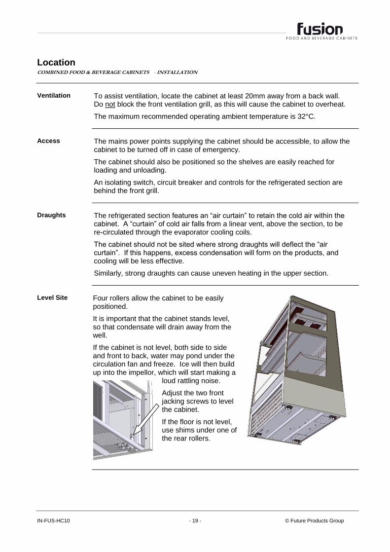
Level Site Four rollers allow the cabinet to be easily
positioned.
It is important that the cabinet stands level, so that condensate will drain away from the well.
If the cabinet is not level, both side to side and front to back, water may pond under the circulation fan and freeze. Ice will then build up into the impellor, which will start making a
loud rattling noise.
Adjust the two front jacking screws to level the cabinet.
If the floor is not level, use shims under one of the rear rollers.
Part No. 22958 Rev. P June 2017 - 20 - Fusion, Food & Beverage Cabinet
SERVICING Mains Lead COMBINED FOOD & BEVERAGE CABINETS - SERVICING
Lead Replacement
The mains leads must only be replaced by the manufacturer, their service agent or similarly qualified person, in order to avoid a hazard.
Lighting COMBINED FOOD & BEVERAGE CABINETS - SERVICING
Protection The lighting and low power circuits are protected by a circuit breaker on the
control gear chassis, located behind the front grill of the refrigerated section and on the back of the heated section.
If the lights do not work but the rest of the cabinet is operating, get an electrician to check the lighting circuits.
Caution DO NOT service lights without isolating the cabinet by unplugging it from the
mains supply socket, or turning off the servicing isolation switch.
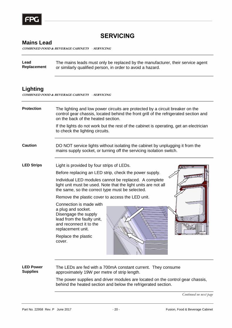
LED Strips Light is provided by four strips of LEDs.
Before replacing an LED strip, check the power supply.
Individual LED modules cannot be replaced. A complete light unit must be used. Note that the light units are not all the same, so the correct type must be selected.
Remove the plastic cover to access the LED unit.
Connection is made with a plug and socket. Disengage the supply lead from the faulty unit, and reconnect it to the replacement unit.
Replace the plastic cover.
LED Power Supplies
The LEDs are fed with a 700mA constant current. They consume approximately 19W per metre of strip length.
The power supplies and driver modules are located on the control gear chassis, behind the heated section and below the refrigerated section.
Continued on next page

IN-FUS-HC10 - 21 - © Future Products Group
Heating COMBINED FOOD & BEVERAGE CABINETS - SERVICING
Heating Elements
Radiant heating elements are used above the shelves, and the lower shelf is directly heated by a contact element.
Temperature probes for the thermostat and thermometer are mounted above the upper shelf.
Element Replacement
To replace the upper radiant element, first remove the screws retaining the wire guard. The element assembly can then be released and a new one fitted.
Because of the restricted space, it is easier to replace the radiant shelf elements by first removing the complete shelf assembly. To do this, the wiring must first be disconnected from behind the back panel.
The base element can only be replaced by fitting a complete element/panel assembly. Note that it has fixings from the back of the cabinet as well as inside.
Temperature Control
The overall temperature of the heated section is controlled by a thermostat, on the back of the cabinet.
Turn clockwise to increase temperature.
It is important to confirm that the cabinet temperature gauge indicates at least 68°C.
Thermometer Battery Replacement
The digital thermometer is self-contained, fitted with two batteries.
The thermometer is a push-fit in the cabinet, and may be extracted to replace the batteries.
Fresh batteries should be fitted in pairs.
Continued on next page

Part No. 22958 Rev. P June 2017 - 22 - Fusion, Food & Beverage Cabinet
Heating cont. COMBINED FOOD & BEVERAGE CABINETS - SERVICING
Control Gear The control gear for the heated section is located under a removable panel, on
the back of the cabinet.
The MCB and LED power supply are here, together with connections to the heating and lighting circuits etc.
Ventilation Fan A fan is mounted on the upper back of
the cabinet. This circulates air through the top of the cabinet, to prevent surfaces becoming too hot to touch.
It is important that the fan is operating correctly, and that its grill is not blocked with dust and fluff.
Insufficient air circulation will allow surface temperatures to rise, and can result in shortened LED life.
Refrigeration COMBINED FOOD & BEVERAGE CABINETS - SERVICING
Caution DO NOT attempt to service the refrigeration equipment without isolating
the cabinet by unplugging it from the mains supply socket.
Access to Control Gear etc.
The control gear chassis is reached by removing the louver panel from the front of the cabinet.
The chassis houses the refrigeration controller, mains isolation switch, MCB, LED power supply and the terminal block for all interconnections.
Remove the four screws retaining the lower side panel to access the interior of the chassis.
Continued on next page

IN-FUS-HC10 - 23 - © Future Products Group
Refrigeration cont. COMBINED FOOD & BEVERAGE CABINETS - SERVICING
Access to Condensing Unit etc.
The condenser unit and boil off element can be reached from the front and rear of the cabinet.
Remove the fixing screws to open the cabinet back panel and to remove the front louvers.
Condenser Ventilation
For efficient refrigeration performance, the condenser radiator and front and rear louvers must be kept clean. Failure to do this will lead to a build-up of dust, and restricted airflow will prevent the unit from working properly.
The compressor may overheat and the cabinet temperature may rise.
Regular vacuuming will prevent a build-up of dust and fluff, however, the condenser and radiator should be cleaned with compressed air during the mandatory three monthly service checks by a refrigeration engineer.
Be very careful not to bend or damage the soft aluminium fins when vacuuming the radiator. If the fins are flattened, airflow will be restricted and overheating will again result.
Controller Adjustment
The controller must NOT be tampered with by an unqualified person.
The indicated temperature will be lower than the air temperature inside the cabinet, because the refrigeration compressor is controlled in response to the exit air temperature from the evaporator cooling coil.
The controller can also display fault messages, caused by condenser overheating or low refrigerant gas pressure.
Continued on next page

Part No. 22958 Rev. P June 2017 - 24 - Fusion, Food & Beverage Cabinet
Refrigeration cont. COMBINED FOOD & BEVERAGE CABINETS - SERVICING
Probe Locations
The temperature control probe is positioned in the off air stream from the evaporator coil.
A second probe, inserted in the fins of the coil controls the defrost termination.
A third probe (temperature sensor), is located in a pocket on the discharge line from the compressor. The function of this probe is to avoid the refrigeration system overheating.
Thermometer A barrel thermometer is located in
the return air duct, at the front of the cabinet.
It will therefore indicate the temperature of the air returning from the display area, before passing through the cooling coil. This will be slightly higher than the product temperature.
Fan Deck The fan deck is fitted with two fans, and is electrically connected to the cabinet with a plug and socket.
After removing the retaining screws, the complete assembly can be removed for servicing.
Take care to avoid trapping cables with the metalwork, when re-assembling
Continued on next page

IN-FUS-HC10 - 25 - © Future Products Group
Refrigeration cont. COMBINED FOOD & BEVERAGE CABINETS - SERVICING
Condensate Disposal
The condensate disposal system consists of a water tray, a water level detector and a boil-off element with an over temperature cut-out.
If the element fails, it may be replaced by springing it from the mounting bracket. Cut and splice the leads and protect with heat-shrink sleeves.
ACR Fault Finding Guide
First check if the condensate water level probe in the ACR tank is dirty and needs cleaning (a dirty probe may either fail to detect water, or give a false indication of water) clean if required.
Check the Finder Level Control unit sensitivity range adjustment is set to 75k. If the sensitivity is set too low, the Finder Level Control unit may not detect the condensate water and won’t switch on the ACR element. If the sensitivity is set too high, the Finder Level Control unit may get a false indication of the condensate water and switch on the ACR element without water present.
Fault: ACR element is on continuously when no condensate water is present.
Test: Check if the Finder Level Control unit is faulty by disconnecting the probe wire from terminal B1 on the Finder Level Control unit. With the cabinet power turned on and after waiting 10 seconds, check for 230V across terminals 11 and 14. If 230v is not present across terminals 11 & 14, replace the Finder Level Control unit.
Fault: ACR element does not heat even though condensate water is present and touching the water level probe.
Test: First check the ACR unit has a 230V power supply.
Next, check the Finder Level Control unit water sensing circuit by short-circuiting the level sensor terminals B1 & B3. Turn the cabinet power on and wait 10 seconds and then check if the ACR element heats. If the element heats, check for an open circuit in the water sensing probe circuit and clean the probe.
If the element does not heat, turn the cabinet power off and take the element wire out of terminal 11 and wire into terminal 14 on the Finder Level Control unit. Turn the cabinet power on and wait 10 seconds and then check if the ACR element heats. If the element heats, replace the Finder Level Control Unit. If the element does not heat replace the element and Therm-O-Disc assembly.
Note: The element and Therm-O-Disc are supplied as a complete assembly.
Continued on next page

Part No. 22958 Rev. P June 2017 - 26 - Fusion, Food & Beverage Cabinet
ON
Time
Refrigeration cont. COMBINED FOOD & BEVERAGE CABINETS - SERVICING
Temperature Regulator XR40CX
Model XR40CX is a microprocessor based controller. It is provided with three NTC or PTC probe inputs, the first one for temperature control, the second one, to be located
onto the evaporator, to control the defrost termination temperature, the third one, optional, to connect to the HOT KEY terminals to signal the condenser temperature alarm or to display a temperature.
The indicated set-point temperature will be lower than the air temperature inside the cabinet, because the refrigeration compressor is controlled in response to the exit air temperature from the evaporator cooling coils.
The HOT KEY output allows one to programme the controller by means the HOT KEY programming keyboard.
The instrument is fully configurable through special parameters that can be easily programmed through the keyboard.
XR40CX Compressor Control
The regulation is performed according to the temperature measured by the thermostat probe with a positive differential from the set point: if the temperature increases and reaches set point plus differential the compressor is started and then turned off when the temperature reaches the set point value again.
In case of a fault in the thermostat probe the start and stop of the compressor are timed through parameters COn and COF.
XR40CX Defrost Control
Parameters are used to control the interval between defrost cycles (IdF), its maximum length (MdF) and two defrost modes: timed or controlled by the evaporator’s probe (P2P).
In this cabinet, the start of the defrost cycle is timed, but the cycle will be terminated as soon as the defrost probe reaches the pre-determined temperature.
At the end of defrost dripping time is started, its length is set in the FSt parameter. With FSt =0 the dripping time is disabled
Continued on next page

IN-FUS-HC10 - 27 - © Future Products Group
Refrigeration cont. COMBINED FOOD & BEVERAGE CABINETS - SERVICING
XR40CX Key Functions KEY FUNCTION
To display target set point; in programming mode it selects a parameter or confirm an operation
(DEF) To start a manual defrost
(UP): To see the max. stored temperature; in programming mode it browses the parameter codes or increases the displayed value
(DOWN): To see the min stored temperature; in programming mode it browses the parameter codes or decreases the displayed value
To switch the instrument off, if onF = oFF. Not enabled
To lock & unlock the keyboard
To enter into programming mode
To return to the temperature display mode
XR40CX LED Functions LED MODE FUNCTION
ON Compressor enabled
Flashing Anti-short cycle delay enabled
ON Defrost enabled
Flashing Drip time in progress
ON An alarm is occurring
ON Continuous cycle is running
ON Energy saving enabled
ON Measurement unit
Flashing Programming phase
Continued on next page

Part No. 22958 Rev. P June 2017 - 28 - Fusion, Food & Beverage Cabinet
Refrigeration cont. COMBINED FOOD & BEVERAGE CABINETS - SERVICING
XR40CX Min & Max Recorded Temperature
Press and release the key.
Lo will be displayed followed by the minimum temperature recorded.
Press the key again or wait 5s to restore the normal display.
Press and release the key.
Hi will be displayed followed by the maximum temperature recorded.
Press the key again or wait 5s to restore the normal display.
XR40CX Reset Max/Min Temperature Memory
Press the SET key for more than 3s, while the max. or min. temperature is displayed. (rSt message will be displayed)
To confirm the operation the rSt message starts blinking and the normal temperature will be displayed.
XR40CX Display the Set-point
To show the set-point value, press and immediately release the SET key.
Press and immediately release the SET key or wait for 5 seconds to display the probe temperature again.
XR40CX Change the Set-point
To change the set-point value, press the SET key for more than 2 seconds; The value of the set-point will be displayed and the °C or °F LED starts blinking;
To change the set value push the or arrows within 10s.
To memorise the new set-point value push the SET key again or wait 10s.
XR40CX Start a Manual Defrost
To start a manual defrost, press the (DEF) key for more than 2 seconds.
XR40CX Programming Mode
Enter the Programming mode by pressing the keys for 3s (the °C or °F LED starts blinking).
Use the or keys to select the required parameter.
Press the key to display its value.
Use the or keys to change its value.
Press to store the new value and move to the following parameter.
To exit Programming mode, press or wait 15s without pressing a key.
NOTE: the set value is stored even when the procedure is exited by waiting for the time-out to expire.
Continued on next page

IN-FUS-HC10 - 29 - © Future Products Group
Refrigeration cont. COMBINED FOOD & BEVERAGE CABINETS - SERVICING
XR40CX The Hidden Menu
The hidden menu includes all the parameters of the instrument.
TO ENTER THE HIDDEN MENU
Enter the Programming mode by pressing the keys for 3s, (the °C or °F LED starts blinking).
Release the keys, then press the keys again, for more than 7s. The Pr2 label will be displayed immediately followed from the Hy parameter.
NOW YOU ARE IN THE HIDDEN MENU.
Select the required parameter.
Press the key to display its value
Use or to change its value.
Press to store the new value and move to the following parameter.
To exit: Press or wait 15s without pressing a key.
NOTE 1: If no parameter is present in Pr1, after 3s the noP message is displayed. Keep the keys pushed till the Pr2 message is displayed.
NOTE 2: The set value is stored even when the procedure is exited by waiting for the time-out period to expire.
TO MOVE A PARAMETER FROM THE HIDDEN MENU TO THE FIRST LEVEL AND VICEVERSA.
Each parameter present in the HIDDEN MENU can be removed or put into “THE FIRST LEVEL” (user level) by pressing
In HIDDEN MENU when a parameter is present in the First Level the decimal point is shown.
XR40CX Locking and Unlocking the Keyboard
To lock the keyboard, press the keys for more than 3 s.
The POF message will be displayed, followed by the previous temperature display.
If a key is pressed more than 3s the POF message will be displayed.
To unlock the keyboard, press the keys for more than 3s, till the Pon message is displayed.
Continued on next page

Part No. 22958 Rev. P June 2017 - 30 - Fusion, Food & Beverage Cabinet
Refrigeration cont. COMBINED FOOD & BEVERAGE CABINETS - SERVICING
FPG Settings Note that the following settings are Dixell factory defaults. Refer to the
Specification section for the correct FPG settings for your cabinet.
Dixell Default Settings
Label Name Range Default Setting
Set Set point LS÷ US -5.0
Hy Differential 0,1÷25.5°C/ 1÷ 255°F 2.0
LS Minimum set point -50°C÷SET/-58°F÷SET -50.0
US Maximum set point SET÷110°C/ SET ÷ 230°F 110
Ot Thermostat probe calibration -12÷12°C /-120÷120°F 0.0
P2P Evaporator probe presence n=not present; Y=pres. Y
OE Evaporator probe calibration -12÷12°C /-120÷120°F 0.0
P3P Third probe presence n=not present; Y=pres. n
O3 Third probe calibration -12÷12°C /-120÷120°F 0
P4P Fourth probe presence n=not present; Y=pres. n
O4 Fourth probe calibration -12÷12°C /-120÷120°F 0
OdS Outputs delay at start up 0÷255 min 0
AC Anti-short cycle delay 0 ÷ 50 min 1
rtr P1-P2 percentage for regulation 0 ÷ 100 (100=P1 , 0=P2) 100
CCt Continuous cycle duration 0.0÷24.0h 0.0
CCS Set point for continuous cycle (-55.0÷150,0°C) (-67÷302°F) -5
COn Compressor ON time with faulty probe 0 ÷ 255 min 15
COF Compressor OFF time with faulty probe 0 ÷ 255 min 30
CF Temperature measurement unit °C ÷ °F °C
rES Resolution in=integer; dE= dec.point dE
Lod Probe displayed P1;P2 P1
rEd2 X-REP display P1 - P2 - P3 - P4 - SEt - dtr P1
dLy Display temperature delay 0 ÷ 20.0 min (10 sec.) 0
dtr P1-P2 percentage for display 1 ÷ 99 50
tdF Defrost type EL=el. heater; in= hot gas EL
dFP Probe selection for defrost termination nP; P1; P2; P3; P4 P2
dtE Defrost termination temperature -50 ÷ 50 °C 8
IdF Interval between defrost cycles 1 ÷ 120 ore 6
MdF (Maximum) length for defrost 0 ÷ 255 min 30
dSd Start defrost delay 0÷99min 0
dFd Displaying during defrost rt, it, SEt, DEF it
dAd MAX display delay after defrost 0 ÷ 255 min 30
Fdt Draining time 0÷120 min 0
dPo First defrost after start-up n=after IdF; y=immed. n
dAF Defrost delay after fast freezing 0 ÷ 23h e 50’ 0.0
ALc Temperature alarms configuration rE= related to set; Ab = absolute Ab
ALU MAXIMUM temperature alarm Set÷110.0°C; Set÷230°F 110
ALL Minimum temperature alarm -50.0°C÷Set/ -58°F÷Set -50.0
Continued on next page

IN-FUS-HC10 - 31 - © Future Products Group
Refrigeration cont. COMBINED FOOD & BEVERAGE CABINETS - SERVICING
Dixell Default Settings cont.
Label Name Range Default Setting
AFH Differential for temperat. alarm recovery (0,1 °C÷25,5°C) (1 °F÷45°F) 1
ALd Temperature alarm delay 0 ÷ 255 min 15
dAO Delay of temperature alarm at start up 0 ÷ 23h e 50’ 1.3
AP2 Probe for temperat. alarm of condenser nP; P1; P2; P3; P4 P4
AL2 Condenser for low temperat. alarm (-55 ÷ 150°C) (-67÷ 302°F) -40
AU2 Condenser for high temperat. alarm (-55 ÷ 150°C) (-67÷ 302°F) 110
AH2 Differ. for condenser temp. alar. recovery [0,1 °C ÷ 25,5°C] [1 °F ÷ 45°F] 5
Ad2 Condenser temperature alarm delay 0 ÷ 254 (min.) , 255=nU 15
dA2 Delay of cond. temper. alarm at start up 0.0 ÷ 23h 50’ 1,3
bLL Compressor OFF for condenser low temperature alarm n(0) - Y(1) n
AC2 Compressor OFF for condenser high temperature alarm n(0) - Y(1) n
i1P Digital input polarity oP=opening; CL=closing cL
i1F Digital input configuration EAL, bAL, PAL, dor; dEF; Htr, AUS EAL
did Digital input alarm delay 0÷255min 5
Nps Number of activation of pressure switch 0 ÷15 15
odc Compress status when open door no; Fan; CPr; F_C no
rrd Regulation restart with door open alarm n – Y y
HES Differential for Energy Saving (-30°C÷ 30°C) (-54°F÷ 54°F) 0
Adr Serial address 0÷247 1
PbC Kind of probe Ptc; ntc ntc
onF on/off key enabling nu, oFF; ES nu
dP1 Room probe display -- --
dP2 Evaporator probe display -- --
dP3 Third probe display -- --
dP4 Fourth probe display -- --
rSE Set operating value actual set --
rEL Software release -- --
Ptb Map code -- --
XR40CX Hot Key
To program the controller from a Hot Key:
Turn OFF the instrument.
Insert a programmed Hot Key into the 5 PIN socket and then turn the Controller ON.
The parameter list of the Hot Key is automatically downloaded into the Controller memory, the doL will blink, followed a by a flashing End.
After 10 seconds the instrument will restart working with the new parameters.
Remove the Hot Key.
NOTE the message Err is displayed if programming fails. In this case turn the unit off and then on again, if you want to restart the download again, or remove the Hot Key to abort the operation.
Continued on next page

Part No. 22958 Rev. P June 2017 - 32 - Fusion, Food & Beverage Cabinet
Refrigeration cont. COMBINED FOOD & BEVERAGE CABINETS - SERVICING
XR40CX Alarm Signals
Message Cause Outputs
P1 Room probe failure Compressor output acc. to par. Con and COF
P2 Evaporator probe failure Defrost end is timed
P3 Third probe failure Outputs unchanged
P4 Fourth probe failure Outputs unchanged
HA Maximum temperature alarm Outputs unchanged.
LA Minimum temperature alarm Outputs unchanged.
HA2 Condenser high temperature It depends on the Ac2 parameter
LA2 Condenser low temperature It depends on the bLL parameter
dA Door open Compressor according to rrd
EA External alarm Output unchanged.
CA Serious external alarm (i1 F=bAL) All outputs OFF.
CA Pressure switch alarm (i1 F=PAL) All outputs OFF
XR40CX Alarm Recovery
Probe alarms P1, P2, P3 and P4 start some seconds after the fault in the related probe; they automatically stop some seconds after the probe restarts normal operation. Check connections before replacing the probe.
Temperature alarms HA, LA, HA2 and LA2 automatically stop as soon as the temperature returns to normal values.
Alarms EA and CA (with i1 F=bAL) recover as soon as the digital input is disabled. Alarm CA (with i1 F=PAL) recovers only by switching off and on the instrument.
XR40CX Other Messages
Message Cause
Pon Keyboard unlocked.
PoF Keyboard locked
noP In programming mode: none parameter is present in Pr1
On the display or in dP2, dP3, dP4: the selected probe is not enabled
noA No alarm is recorded.
XR40CX Connections

IN-FUS-HC10 - 33 - © Future Products Group
SPECIFICATIONS
Mechanical COMBINED FOOD & BEVERAGE CABINETS - SPECIFICATIONS
CABINET MODEL
IN-FUS-HC10-A004
Cold Section Hot Section
Height 1480 mm
Width 1009 mm
Depth 714 mm
Levelling adjustment +30mm
Dry Weight 230 kg
Number of Shelves 1 + base 1 + base
Display Area 0.7 m2 0.72 m
2
Refrigerant R-134a N/A
Refrigerant charge, see Cabinet Rating Label
approx. 400 g N/A
Condensate capacity 3 litres N/A
Electrical COMBINED FOOD & BEVERAGE CABINETS - SPECIFICATIONS
CABINET MODEL
IN-FUS-HC10-A004
Cold Section Hot Section
Voltage 220-240 V 50 Hz 1
Maximum Power 1.2 kW 1.9 kW
ACR Element Power 400 W N/A
Maximum Current 5.3 A 8.3 A
Connection Three core cable with
3 pin plug Three core cable with
3 pin plug
Lights 2 x LED strips
Cool White 2 x LED strips Warm White
Energy Consumption in 25ºC, 60%RH Ambient 0.75 kWh/h

Part No. 22958 Rev. P June 2017 - 34 - Fusion, Food & Beverage Cabinet
Cabinet Performance COMBINED FOOD & BEVERAGE CABINETS - SPECIFICATIONS
Refrigerated Section Performance
Operating Temperature Average Internal Humidity Climatic Class 3 Test Conditions
+2° to +4°C 70% RH 25°C Ambient with 60% RH
Controller Settings COMBINED FOOD & BEVERAGE CABINETS - SPECIFICATIONS
Application Specific Settings
The following table specifies the settings for the Dixell XR40CX Controller which are specifically for this FPG cabinet.
XR40CX Settings
Parameter Description Setting Unit / Range
Set Set Point -4 degC
Hy Differential 3.5 degC
P3P Third Probe Used Y n=no, Y=yes
AC Anti Short Cycle Delay 0 Min
C0n Comp On Time - Faulty Probe 4 Min
C0F Comp Off Time - Faulty Probe 6 Min
dtE Defrost Terminate Temp 6 degC
IdF Interval Between Defrosts 2 Hrs
dFd Display During Defrost DEF rt, it, Set, DEF
AP2 Probe For High Discharge Temp Alarm P3 nP, P1, P2, P3, P4
AU2 High Discharge Temp Alarm Set Point 100 degC
AH2 High Discharge Temp Alarm Diff 25 degC
Ad2 High Discharge Temp Alarm delay 0 Min
dA2 High Discharge Alarm Delay At Start 0 Min
AC2 Comp Off For High Discharge Temp Alarm Y(1) n(0)=no, Y(1)=yes

IN-FUS-HC10 - 35 - © Future Products Group
Compliance COMBINED FOOD & BEVERAGE CABINETS - SPECIFICATIONS
Safety Aspects This cabinet has been designed to comply with the relevant requirements of the
following specifications:
AS/NZS 3100 : General Requirements for Electrical Equipment
IEC 60335-1: General Requirements
IEC 60335-2-24: Particular requirements for refrigerating appliances, ice- cream appliances and ice-makers
IEC 60335-2-34: Particular requirements for motor compressors
IEC 60335-2-49: Particular requirements for commercial electric hot cupboards
IEC 60335-2-89: Particular requirements for commercial refrigerating appliances with an incorporated or remote refrigerant condensing unit or compressor
Hazardous Substances The cabinet does not contain any of the following, in its construction:
Asbestos
PCBs (Oils containing polychlorinated biphenyl)
Mercury
Improvements COMBINED FOOD & BEVERAGE CABINETS - SPECIFICATIONS
On-going Development
FPG reserves the right to change specifications and construction, as part of on-going product improvement.

Part No. 22958 Rev. P June 2017 - 36 - Fusion, Food & Beverage Cabinet
ELECTRICAL CIRCUIT DIAGRAM
Model: IN-FUS-HC10-A004 1000 mm Open-front Food & Beverage Cabinet

IN-FUS-HC10 - 37 - © Future Products Group
SPARE PARTS
Cabinet Serial Number
When ordering spare parts, it is important to quote the Serial Number printed on the label fixed to the cabinet. This will enable FPG to trace details of the build specification of your particular cabinet, and hence ensure that spare parts are fully compatible. To satisfy warranty conditions, and ensure optimum performance, use only FPG supplied spare parts.
Part Description FPG Part No
Side glass kit 68554
Chicken Tray – base with load limit 68626
Chicken Tray – top shelf 68627
One-piece Shelf 58546
LED power supply 24V 60W 21613
LED Driver 700mA 25672
Anti-surge thermistor 10 Ohm 3A 22354
Cold section top light LED assembly 72286
Cold section top light plastic cover 25316
Cold section bottom light LED assembly 71614
Cold section bottom light plastic cover 26953
Heated section top light LED assembly 71612
Heated section top light plastic cover 25315
Heated section shelf light LED assembly 72312
Heated section shelf light plastic cover 25337
Ventilation fan 21614
Condensate Water Sensor, Finder 72.01.8.240.0000 25309
ACR Boil off Element 400W 18274
Quartz Heating Element 600W 23173
Thermostat 90°C 26207
Thermostat Knob 12849
Danfoss SC18 Compressor 21669
Condenser Fan Unada 200mm 1800rpm 72935
Evaporator EBM Papst ACi4420 10709
Barrel Thermometer 11924
Digital Thermometer 23189
Digital Thermometer Battery 26189
Toroid Ring 12.5mm 22565
Circuit Breaker 6 Amp 10522
Mains Switch DPST 16A 250V Rocker 23876
Light Switch Rocker 15811
Dixell XR40CX digital refrigeration controller 21219
NTC temperature probe 15870
EMI Line Filter 22873
Filter Toroid 23217(22565)
Thermal Fuse G4A01152C 25612
Product Manual for Fusion Food & Beverage cabinet 25706

Part No. 22958 Rev. P June 2017 - 38 - Fusion, Food & Beverage Cabinet
MECHANICAL DRAWINGS
IN-FUS-HC10-A004

IN-FUS-HC10 - 39 - © Future Products Group

Part No. 22958 Rev. P June 2017


