68
INDUSTRIAL BELT AND DRIVE P REVENTIVE MAINTENANCE For a long and trouble-free service life E2/20087

IndustrIal Belt and drIve PreventIve MaIntenance
For a long and trouble-free service life
E2/20087

Throughouttheyears,theGatesCorporationhasplayedakeyroleinthecreationanddevelopmentofhighqualitybelts. Gates’ continuous product development has resulted in a comprehensive programme of V-belts, synchronous belts, tensioners, pulleys, flexible couplings and complete drive systems covering a multitude of applications. TypicalexamplesareV-belts suchasPredator®,Quad-Power®II,SuperHC®MN,Hi-Power®,Predator®PowerBand®,Quad-Power®IIPowerBand®,Polyflex®JB™andMicro-V®.
The latest innovations in Gates' synchronous belt rangearePolyChain®GTCarbon™,themostpowerfulpolyurethanesynchronousbelt in themarketwithpatented carbon tensile cord design, designed for hightorque,lowspeeddrives,andPowerGrip®GT3rubber synchronous belt with optimised GT tooth profile available in small as well as in large pitches, covering a wide range of industrial applications.
AllGatesEuropeanPowerTransmissionoperationsareISO9001andISO14001accredited.TheinternationalISO9001assessmentcoversdesign,development,production, installation and servicing of products and is evidence of Gates’ solid commitment to quality.GatesalsoachievedtheISO14001standardby demonstrating that environmental issues and protectionaremanagedwithinacoordinatedframeworkof controls and well-defined procedures.
hIGh PErforMAncE And coMPrEhEnSIVE
Product rAnGE
® Registered trademark of Gates Corporation.

1
I. Introduction
1. Whypreventivemaintenance? ................................................ 2 2. Componentsofagoodmaintenanceprogramme ........... 2
II. A safe working environment .............................................. 3
III. Preventive “routine” maintenance 1. Simple drive inspection .............................................................. 4 2. Frequencyofinspection............................................................. 4 3. When to perform preventive maintenance ........................ 4
IV. drive shutdown and thorough inspection
1. Guard inspection ..........................................................................5 2. Belt inspection ...............................................................................5 3. Pulley inspection ...........................................................................6 4. Checkalignmenttolerances ......................................................6 5. Checkotherdrivecomponents ................................................6 6. Checkbelttension ......................................................................... 7
V. Belt and pulley installation 1. V-belt installation ........................................................................... 9 2. Synchronous belt installation..................................................10 3. Pulley installation and alignment .........................................10
VI. Belt identification 1. Industrial belt types ...................................................................11 2. Sections and nominal dimensions: V-belts ....................................................................22 3. Sections and nominal dimensions: synchronous belts .............................................25
VII. cross-reference list: V-belts ................................................28
VIII. cross-reference list: synchronous belts ...................30
IX. Belt drive performance evaluation 1. Upgrading drive performance ...............................................32 2. Improving poor drive performance .....................................32
X. troubleshooting guide: V-belts 1. Problems on V-belt drives ........................................................33 2. Problem/cause/solutiontable ...............................................34
XI. troubleshooting guide: synchronous belts 1. Problems on synchronous belt drives .................................38 2. Problem/cause/solutiontable ...............................................39
XII. troubleshooting methods and tools 1. Eyes,ears,noseandhands ......................................................41 2. Squirtbottlewithsoapywater ..............................................41 3. Ball of string ..................................................................................41 4. Belt and sheave gauge ..............................................................41 5. Longstraightedge .....................................................................41 6. MROengineeringtoolbag ......................................................41
XIII. Belt storagei
1. General guidelines ......................................................................43 2. Methods of storage .....................................................................43 3. Effectsofstorage .........................................................................43
XIV. technical data .................................................................. 44
XV. Support .............................................................................. 58
IndEX
GAtES coSt SAVInG ProGrAMMEThe Gates cost saving programme includes plant surveys toevaluatecurrentbeltdriveefficienciesand the calculation of concrete cost saving opportunities for a specific drive.Formoreinformationonthissubject,seepage58.Onpage61youwillfindan inquiry sheet foranexpertiseofyourmachinepark.

2
I. IntroductIon
Improper belt or pulley installation
Environmental factors
Improper drive maintenance
Poor drive design
defective drive components
Sources of drive problems
Improper belt storage or handling
1. Why preventive maintenance?When compared to chain drives (with constant lubrication problems), or gear drives (with mechanical problems and high costs), belt drives are the most cost-effective and reliable means of power transmission. This reliability can however only be obtained when belts and drives are properly maintained.
The potential for long service life is built into every Gates belt. When coupled to a regular maintenance programme, your belts and drives will run relatively trouble-free for a long period of time. Always inspect belts and drives before they fail. This will reduce costly downtime and production delays.
2. components of a good maintenance programmeA complete and effective maintenance programme should include following elements:
• maintainingasafeworkingenvironment;• regularbeltdriveinspections;• properbeltinstallationprocedures;• beltproductknowledge;• beltdriveperformanceevaluations;• troubleshooting.
All these aspects will be dealt with in the different sections of this manual.
this manual has been designed as a guide to help you install and maintain Gates industrial belts, including standard V-belts, multi-ribbed belts and synchronous belts. through proper installation and maintenance, the service life of your belt drives will dramatically improve — reducing downtime and production standstills.

3
It is common sense to establish a safe working environment in and around your belt drives. Besides making maintenance easier, the following precautions will ensure safety for the operator.
1. trained personnelAlwayshavetrainedpersonnelworkingonyourbeltdrives.
2. Always turn equipment offTurnoffthepowertothedrivebeforeyoustartworking,evenifyouaregoingforabriefinspection.Lockthecontrolboxand tag it with a warning sign “Down for maintenance. Do notturnpoweron.”Keepthekeyinyourpocket.Foraddedsafety, and if possible, remove fuses. Inspecting the drive usually involves watching the machine running - but never touch it before it stops.
3. check position of componentsMakesureallmachinecomponentsare ina“safe”position.Place fly-wheels, counterweights, gears and clutches in a neutral position to avoid accidental movements. Always follow the manufacturer’s recommendations for safe maintenance practices.
4. Wear proper clothingNeverwear looseorbulkyclothes (e.g. ties, loose sleeves,lab coats) around belt drives. Wear gloves when inspecting pulleys toavoidbeingcutbynicksor sharplywornpulleyedges.
5. Maintain safe access to the drivesKeep the areas around the drive free of clutter, debris and otherobstructions.Floorsshouldbecleanandfreeofoilanddebris to ensure good footing and balance of the operator whilstworkingonthemachine.
6. drive guardsAlways keep drives properly guarded. Every beltdrive must be completely guarded while in operation. Amakeshift,partialguardisoftenmoredangerous,sinceitgives a false sense of security and encourages unsafe action. Besides being a safety asset, a goodguardmakes your
No loose or bulky clothing.
A properly guarded belt drive.
Do not clutter area around belt drive.
A properly designed guard has following features:• itcompletelyenclosesthedrive;
• itisequippedwithgrillsorventsforgoodventilation;
• thesizeoftheopeningsmustbeadequate,i.e.smallenough toprevent"pinchpoints";
• itispreferablyequippedwithanautomaticshut-offdevice whichdeactivatesthedriveassoonastheguardisremoved;
• ithasaccessibleinspectiondoorsorpanels;
• itcaneasilyberemovedandreplacedifdamaged;
• wherenecessary,itshouldprotectthedrivefromweather, debris and damage.
maintenance job easier since it protects the drive from outside damaging influences.
7. test runBeforeyouputyourdrivebackintonormaloperation,havea"testrun"tocheckwhethereverything functionsnormally. Makeanyverificationsnecessaryand takecorrectiveaction if needed.
II. A SAfE WorkInG EnVIronMEnt

4
III. PrEVEntIVE “routInE” MAIntEnAncE
Maintenance has two aspects: shorter, regular preventive inspections and thorough inspections with a longer period of machine shutdown. this section deals with the first type of routine inspection.
3. When to perform preventive maintenanceThe following guidelines will help you establish a preventive maintenance schedule.
critical drivesAquickvisualandhearinginspectionmaybeneededevery onetotwoweeks.
normal drivesWithmostdrives,aquickvisualandhearinginspectioncanbe performed once a month.
complete inspectionA drive shutdown, for a thorough inspection of belts or pulleys andotherdrivecomponentsmayberequiredevery three to sixmonths. See section IV.
1. Simple drive inspectionAgoodway tobeginpreventivemaintenance ismakingperiodic drive inspection a normal part of your maintenance rounds.
Look and listenLookand listen for anyunusual vibrationor soundwhileobserving the guarded drive in operation. A well-designed andmaintaineddrivewilloperatesmoothlyandquietly.
Guard inspectionInspect the guard for looseness or damage. Keep it free of debris and grime buildup. Any accumulation of material on the guard will act as insulation and could cause the drive to run hotter. Temperature is an important factor of belt performance and durability.Forexample,above60°Caninternaltemperatureincreaseof10°C(50°F)–orapproximately20°C(68°F)riseinambienttemperature–maycutV-beltlifeinhalf.
oil and greaseAlsolookforoilorgreasedrippingfromtheguard.Thismayindicateover-lubricatedbearings.Oilandgreaseattackrubbercompounds, causing them to swell and distort. This will lead to early belt failure.
AttachmentsFinally, checkmotormounts forproper tightness. Checktakeupslotsor rails to see that theyarecleanand lightlylubricated.
2. frequency of inspectionThe following factorswill influence the frequencyofdriveinspection:
• driveoperatingspeed;
• driveoperatingcycle;
• criticalnatureofequipment;
• temperatureextremesinenvironment;
• environmentalfactors;
• accessibilityofequipment.
Experiencewithyourownequipmentwillbethebestguideto how often you need to inspect the belt drives. High speeds,heavyloads,frequentstart/stopconditions,extremetemperaturesanddrivesoperatingoncriticalequipmentwillmeanmorefrequentinspections.

5
IV. drIVE ShutdoWn And thorouGh InSPEctIon
Belt inspection.
Once the drive has been disconnected from power supply and tagged, and the machine components are in safe position, remove the guard and begin inspection.
1. Guard inspectionCheckguardsforwearorpossibledamage.Lookforsignsofwearorrubbingagainstdrivecomponents. Cleanthemtoprevent their becoming insulated and closed to ventilation. Cleanoffanygreaseoroilthatmayhavebeenspilledontothe guard from over-lubricated bearings.
2. Belt inspectionBy observing signs of unusual belt wear or damage, you will be able to troubleshoot possible drive problems.
Markapointonthebelt,oroneof thebeltsonamultipleV-beltdrive.Workyourwayaroundthebelt(s),checkingforcracks,frayedspots,cutsorunusualwearpatterns.
Checkthebelt forexcessiveheat. Beltsdowarmupwhileoperating,buttemperaturesmustnotexceedcertainlimits.Yourhandcantolerateuptoabout45°C(113°F);ifbeltsaretoo hot to touch, troubleshooting may be needed.
In thatcase, check the temperature rangeof thebeltyou are using.
Beltsshouldbereplacediftheyshowobvioussignsofcracking,fraying, unusual wear or loss of teeth in a synchronous belt.
Belt drives regularly require a thorough inspection. By following the list below, you can maintain a drive efficiently, safely and with very little effort. When properly maintained and used under normal conditions, a well-designed industrial belt drive is capable of operating for several years.
Preventive maintenance checklist
1. Turnoffpowertothedrive.Lockthecontrolboxandtag it with a warning sign “Down for maintenance. Do not turn power on.”
2. Place all machine components in a safe (neutral) position.
3. Removeandinspectguard.Checkforsignsofwearorrubbingagainstdrivecomponents.Cleanguardas needed.
4. Inspect belt for wear or damage. Replace as needed. Page 9 outlines V-belt replacement procedure while page 10 covers synchronous belt replacementprocedure.
5. Inspectpulleysforwearordamage.Replaceifworn.Page10explainspulleyreplacementprocedure.
6. Inspectotherdrivecomponents suchasbearings,shafts,motormountsandtakeuprails.
7. Inspect static conductive earthing system (if used) and replace components as needed.
8. Checkbelttensionandadjustasneeded.
9. Recheckpulleyalignment.
10. Reinstallbeltguard.
11. Turnpoweronandrestartdrive.Lookandlistenforanything unusual.
These steps are covered in detail further in this manual.
Shut off power and lock controls.
Guard inspection.

6
Whenrotatingdrivesbyhandtoensurecorrecttrackingofthebelt,caremustbetakennottotrapfingersbetweenthebeltand pulley. Rotation of large synchronous drives by pulling on thebeltisparticularlyhazardouswhereentrapmentoffingersbetween pulley flanges and the belt can result in immediate amputation of the finger(s).
Tocheckalignment,youwillneedastraightedgeor,forlongcentre distance drives, heavy string. Line the straight edge or string along a machined face of both pulleys as shown on the picture below. Misalignment will show up as a gap between the face of the pulley and the straight edge or string. When using thismethod,make sure thedistancebetween thegroove edge and the outer rim of both pulleys is identical. Pulleyscanalsobecheckedfortiltingwithaspiritlevel.
Use a straight edge to check pulley alignment.
forms of misalignment
* Refer to "4. Check alignment tolerances".
IV. drIVE ShutdoWn And thorouGh InSPEctIon
Angular misaligment Fleetingangle*
Fleetingangle*Parallel misaligment
3. Pulley inspectionIfbeltshavebeenremovedfromthedrive,checkpulleysforunusual wear or obvious signs of damage. Wear is not always obvious.UseGatessheavegaugestocheckV-grooves.Forsynchronousbeltdrives,checkthepulleydiametersoverthewidth of the pulley to ensure they are consistent and meet our tolerances(seeGatesDriveDesignManualE2/20099).
Alwayscheckpulleys forproperalignmentandmounting.Improperly aligned pulleys result in reduced service life.The main causes of misalignment are:• pulleysareimproperlylocatedontheshafts;• motorshaftsanddrivenmachineshaftsarenotparallel;• pulleysaretiltedduetoimpropermounting.
LASEr At-1 laser alignment device
The LASER AT-1 identifiesparallel as well as angular misalignment between the pulleys and is suitable for pulleydiameters of 60mmand larger. Mounted in a few seconds, the laser line projected on the targets allows you toquicklyascertainand
correctmisalignment.Itcanbeusedonbothhorizontallyandverticallymountedmachines.FormoreinformationpleaseseeleafletE2/20121.
Max deviation of pulley alignment
Per 500 mm of drive centre distance
(°) (mm)
V-belt 1/2 5
Polyflex® 1/4 2.5
Micro-V® 1/4 2.5
Synchronous belts 1/4 2.5
4. check alignment tolerancesAs a general rule, the deviation on pulley alignment onV-belt drives should not exceed 1/2° or 5mmper 500mmofdrivecentredistance.Alignmentforsynchronous,Polyflex®andMicro-V®beltsshouldbecontrolledwithin1/4°or2.5mmper500mmofdrivecentredistance.
The greater the misalignment, the greater the chance of belt instability, increased belt wear and V-belt turnover.
5. check other drive componentsAlwaysexaminebearingsforproperalignmentandlubrication.Alsocheckmotormountsforcorrecttightness.Besuretakeuprails are free of debris, obstructions, dirt or rust.

7
6. check belt tensionThe final step is to checkbelt tension, and, if necessary,retension the belt. Note that retensioning is not recommended for synchonous belts.
If too little tension is applied, V-belts may slip or synchronous belts may jump teeth.
The correct tension is the lowest tension at which the belts will transmit power when the drive is at full load. The generalproceduretocheckbelttensionisasfollows.
A.Measureatthecentreofthespan(t)theforcerequiredtodeflectthebeltonthedrive2mmper100mmspanlength(synchronousbelts)or1mmper100mmspan length(V-belts) from its normal position.
B. If the measured force is less than the minimum recommended deflection force, the belts should be tightened.
C.Newbeltscanbetensioneduntilthedeflectionforceperbeltisascloseaspossibletothemaximumrecommendeddeflection force.
D. To facilitate tension measuring Gates has developed the sonic tension meter.
Sonic tension meter
* Thisrecommendationisforuncriticaldriveconfigurations.Forcriticaldrivesindividualdesigncalculationsarerequired.
IV. drIVE ShutdoWn And thorouGh InSPEctIon
Belt Small recommended section pulley deflection diameter force*
mm n min max
Quad-Power® II
XPZ/3VX 56 7 11 60 - 63 8 13 67 - 71 9 14 75 - 80 10 15 85 - 95 11 16 100 - 125 13 19 132 - 180 16 24
XPA 80 - 125 18 27 132 - 200 22 31
XPB/5VX 112 - 118 24 36 125 - 140 27 41 150 - 170 30 47 180 - 200 36 53 212 - 280 38 55 300 - 400 41 64
XPC 180 - 236 50 75 250 - 355 65 95 375 - 530 80 110
Super hc® Mn / Super hc®/ VulcoPlus™
SPZ/SPZ-MN/ 56 - 67 7 10 3V 71 8 11 75 - 80 9 13 85 - 95 10 15 100 - 125 12 17 132 - 180 13 19
SPA/SPA-MN 80 - 95 12 16 100 - 125 14 21 132 - 200 19 28 212 - 250 20 30
SPB/SPB-MN/ 112 - 150 23 36 5V 160 - 200 29 44 212 - 280 36 50 300 - 400 38 58
SPC/SPC-MN 180 - 236 40 60 250 - 355 51 75 375 - 530 60 90
8V/25J 317 - 431 76 113 457 - 610 88 133
8VK 380 - 437 97 145 450 - 600 112 166
hi-Power® / VulcoPower™
Z 60 - 67 6 8 71 - 80 7 9 85 - 100 8 11 106 - 140 9 12 150 - 224 10 14
A 60 - 80 7 12 85 - 90 9 13 95 - 106 10 15 112 - 180 13 20
B 80 - 106 11 17 112 - 118 14 20 125 - 140 15 23 150 - 170 19 27 180 - 1250 22 33
C 150 - 170 21 33 180 24 35 190 26 38 200 - 212 30 45 224 - 265 33 50 280 - 400 38 58
D 300 - 335 51 73 355 - 400 56 82 425 - 560 65 99
The sonic tension meter measures tension by analysing the sound waves which the belt produces when strummed. A belt vibrates at aparticular frequencybasedon its tension, mass and span length. The tension transforms this frequency intoa tension
value. The hand-held tension meter, running on batteries or on the mains (adapter included), is supplied with two types of sensors(rigidandflexible),eitherofwhichisquicklyattachedto meet a specific need.
1. Importantwarning:whenusing the507Csonic tensionmeter, the drive must be switched off.
2. Enterbeltunitweight(providedwithoperatinginstructions),widthandspanonthekeypad.Thisdataremainsinthemeter even after shut-off.
3. Hold the small sensor up to the belt span and strum the beltslightlytomakeitvibrate.
4. Press the “measure” button. The computer processes the variations in sound pressure emanating from the belt span. The belt tension values are displayed on the panel inNewtons. Ifdesired,thebeltspanfrequenciescanbedisplayeddirectlyinHz.
Warning: Gates sonic tension meter is not certified for use in explosion risk areas.
Formoredetailedinformation,e.g.suitabilityofthetensionmeter for different belt product lines, please contact your Gates representative.
For more details on the use of Gates’ sonic tensionmeters, please consult Gates’ sonic tension meter manual (E/20136).
8
IV. drIVE ShutdoWn And thorouGh InSPEctIon
IntensioningaGatesPowerBand®belt,multiplythedeflectionforce (see table on page 7 by the number of belts in the PowerBand®.Thetensiontestercanbeappliedasindicatedabove todeflect theentirePowerBand®,providinga smallboard or metal plate is placed on top of the band so that all belts are deflected uniformly. As a reference for measuring deflection, a straight edge can be laid across the pulleys. If thedeflectionforceexceeds30kg(66pounds)-themaximumreading on the tester - use a large spring scale or consult your Gates representative.
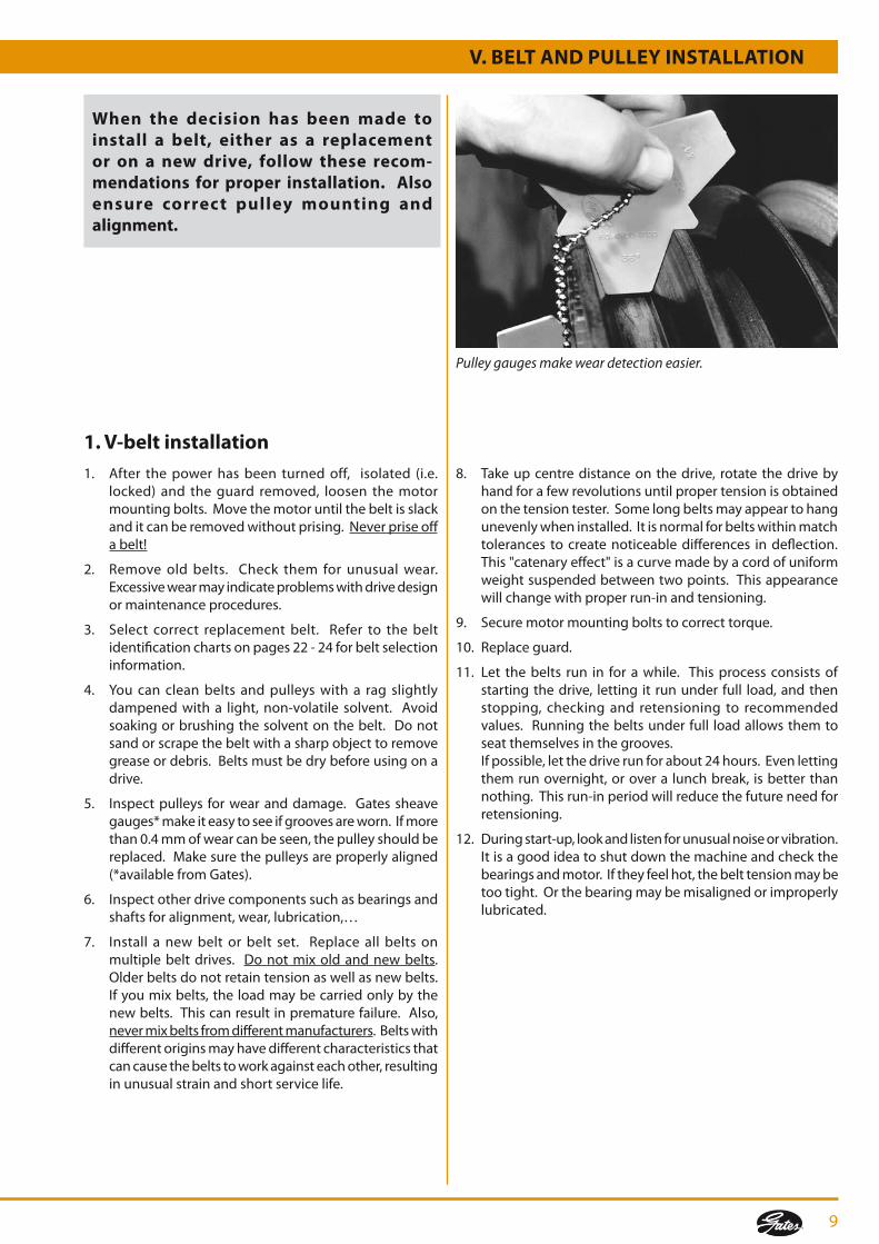
double tension tester
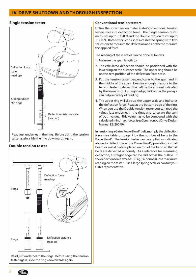
Single tension tester
Read just underneath the ring. Before using the tension tester again, slide the ring downwards again.
Deflection force scale(read up)
Deflection distance scale(read up)
Sliding rubber "O" rings
Read just underneath the rings. Before using the tension tester again, slide the rings downwards again.
Deflection force (read up)
Deflection distance (read up)
Rings
Rings
The reading of these scales can be done as follows.
1. Measure the span length (t).
2. The calculated deflection should be positioned with the lower ring on the distance scale. The upper ring should be onthezeropositionofthedeflectionforcescale.
3. Put the tension tester perpendicular to the span and in themiddleofthespan.Exerciseenoughpressuretothetension tester to deflect the belt by the amount indicated by the lower ring. A straight edge, laid across the pulleys, can help accuracy of reading.
4. The upper ring will slide up the upper scale and indicates the deflection force. Read at the bottom edge of the ring. When you use the Double tension tester you can read the values just underneath the rings and calculate the sum of both values. This value has to be compared with the calculatedmin./max.forces(seeSynchronousDriveDesignManualE2/20099).
conventional tension testers
Unlikethesonictensionmeter,Gates’conventionaltensiontesters measure deflection force. The Single tension tester measuresupto±120NandtheDoubletensiontesterupto±300N.Bothtestersconsistofacalibratedspringwithtwoscales: one to measure the deflection and another to measure the applied force.
9
V. BELt And PuLLEy InStALLAtIon
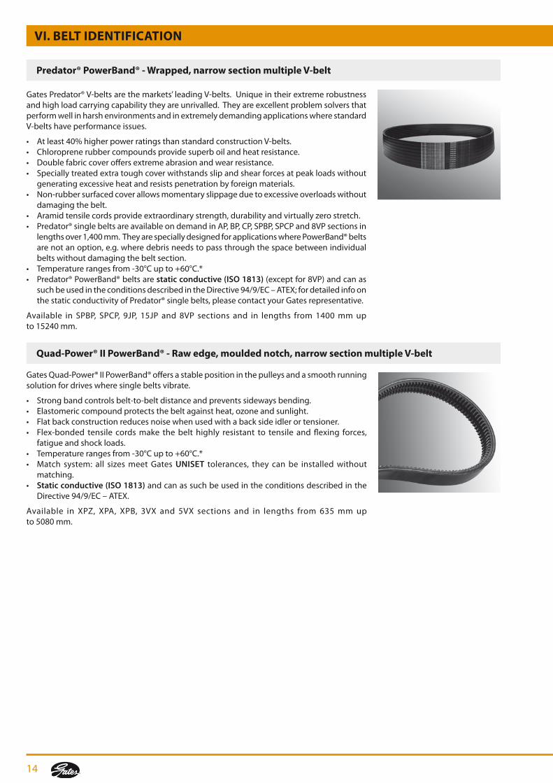
Pulley gauges make wear detection easier.
When the decision has been made to install a belt, either as a replacement or on a new drive, follow these recom-mendations for proper installation. Also ensure correct pulley mounting and alignment.
1. V-belt installation1. After the power has been turned off, isolated (i.e.
locked) and theguard removed, loosen themotormountingbolts.Movethemotoruntilthebeltisslackand it can be removed without prising. Never prise off a belt!
2. Removeoldbelts. Check them for unusualwear.Excessivewearmayindicateproblemswithdrivedesignor maintenance procedures.
3. Select correct replacement belt. Refer to the belt identification charts on pages 22 - 24 for belt selection information.
4. You can clean belts and pulleys with a rag slightly dampened with a light, non-volatile solvent. Avoid soakingorbrushingthesolventonthebelt. Donotsand or scrape the belt with a sharp object to remove grease or debris. Belts must be dry before using on a drive.
5. Inspectpulleys forwearanddamage. Gatessheavegauges*makeiteasytoseeifgroovesareworn.Ifmorethan0.4mmofwearcanbeseen,thepulleyshouldbereplaced.Makesurethepulleysareproperlyaligned(*availablefromGates).
6. Inspectotherdrivecomponentssuchasbearingsandshafts for alignment, wear, lubrication,…
7. Install a new belt or belt set. Replace all belts on multiple belt drives. Donotmixoldandnewbelts. Older belts do not retain tension as well as new belts. Ifyoumixbelts,theloadmaybecarriedonlybythenew belts. This can result in premature failure. Also, nevermixbeltsfromdifferentmanufacturers. Belts with different origins may have different characteristics that cancausethebeltstoworkagainsteachother,resultingin unusual strain and short service life.
8. Takeupcentredistanceon thedrive, rotate thedrivebyhand for a few revolutions until proper tension is obtained on the tension tester. Some long belts may appear to hang unevenly when installed. It is normal for belts within match tolerances to create noticeable differences in deflection. This "catenary effect" is a curve made by a cord of uniform weight suspended between two points. This appearance will change with proper run-in and tensioning.
9. Securemotormountingboltstocorrecttorque.
10. Replaceguard.
11. Let the belts run in for a while. This process consists of starting the drive, letting it run under full load, and then stopping, checkingand retensioning to recommendedvalues. Running the belts under full load allows them to seat themselves in the grooves.
Ifpossible,letthedriverunforabout24hours.Evenlettingthemrunovernight,orovera lunchbreak, isbetterthannothing. This run-in period will reduce the future need for retensioning.
12. Duringstart-up,lookandlistenforunusualnoiseorvibration.Itisagoodideatoshutdownthemachineandcheckthebearings and motor. If they feel hot, the belt tension may be too tight. Or the bearing may be misaligned or improperly lubricated.

10
3. Pulley installation and alignmentItisextremelyimportantthatpulleysbeinstalledandalignedproperly. Any pulley must be correctly assembled, and bolts orsetscrewstightenedtothecorrecttorque.
Most pulleys are attached to the shaft with a tapered bushing which fits a mating tapered bore in the pulley. This type of system consists of a bushing, a pulley and often a setscrew andkey. Bushingscome in severaldiameters. Thisallowsa reduction in theparts inventory required in yourplantbecause one bushing can be used with a number of different sizepulleys.
taper bushesTo install, insert the bushing into the pulley. Match holes (not threads) and slip the entire unit onto the shaft. Put screws into the holes that are threaded in the pulley only. Align the pulleys and tighten the screws. As the bushing is wedged inward, it contacts and grips the shaft.
2. Synchronous belt installation 1. Afterthepowerhasbeenturnedoff,isolated(i.e.locked)
and the guard removed, loosen the motor mounting bolts.Movethemotoruntilthebeltisslackanditcanberemoved without prising. Never prise off a belt!
2. Removeoldbeltandcheckitforunusualwear.Excessivewear may indicate problems with drive design or maintenance procedures.
3. Select correct replacement belt. Refer to the belt identificationchartsonpages25-27forbeltselectioninformation.
4. Pulleys can be cleaned with a rag slightly dampened with a light, non-volatile solvent. Do not sand or scrape the pulley with a sharp object to remove grease or debris. Pulleys must be dry before using on a drive.
5. Inspect pulleys for unusual or excessivewear. Alsocheckalignment.Correctalignmentismorecriticalwithsynchronous belt drives.
6. Checkotherdrivecomponentssuchasbearingsandshaftsfor alignment, wear, lubrication,…
7. Install new belt over pulleys. Do not prise or use force.
8. Takeupcentredistanceonthedriveuntilpropertensionis obtained on the tension tester. Rotate the drives by handforafewrevolutionsandrechecktension.
9. Securemotormountingboltstocorrecttorque.Besureall drive components are secure since any change in drive centres during operation will result in poor belt performance.
10. Although beltswill not require further tensioning,we recommend starting up the drive and observing performance. Lookandlistenforanyunusualnoiseorvibration. It is a good idea to shut down the machine andcheckthebearingsandthemotor.Iftheyfeelhot,the belt tension may be too high. Or the bearings may be misaligned or improperly lubricated.
Taper bush
V. BELt And PuLLEy InStALLAtIon
recommended wrench torque values to use in tightening taper bushes
Bushing no. Screw tightening torque (nm)
1008 5.6
1108 5.6
1210 20.0
1215 20.0
1310 20.0
1610 20.0
1615 20.0
2012 30.0
2517 50.0
2525 50.0
3020 90.0
3030 90.0
3525 115.0
3535 115.0
4030 170.0
4040 170.0
4535 190.0
4545 190.0
5040 270.0
5050 270.0

11
VI. BELt IdEntIfIcAtIonWhen preventive maintenance inspections indicate that belts need replacing, it is important you install the appropriate belts. consequently, you should be able to identify the various types and sizes available to achieve quick and correct replacement.the information on the following pages will help you become familiar with the belt types used in industry.
1. Industrial belt typesGatesmanufacturesmanybelttypestofitnearlyanyapplicationyoucanname.Alwaysmakesureyouselecttheappropriatebeltforyourapplication.Eventhoughtheymaylooksimilar,beltshavedifferentcharacteristics.Donotuselight-dutybeltsonheavy-duty drives, and do not interchange sections. If in doubt carefully measure the top width, or use the pulley gauges.
Super hc® Mn - raw edge, moulded notch, narrow section V-belt
V-belts
TheQuad-Power® IIV-belt features amouldednotchdesignand is ideal forheavy-duty, high-speed V-belt drives. It replaces traditional V-belts on heavy-duty applications where space and weight savings are critical.
• Higherpowerratings:15%higherpowerratingvaluesthanpreviousgenerations,providingthe same service life.
• Mouldednotchconstruction improvesflexibility, reducesbending stressandprovidesimproved performance.
• Toughtensilemembersresistfatigueandshockloads.• Higherpowerratingsthanclassicalsections:narrowerdrivesthroughfewerbeltsreduce
total drive cost.• Temperaturerangesfrom-30°Cupto+60°C.*• Match system: all sizesmeetGatesUNISET tolerances, they can be installed without
matching.• Static conductive (ISO 1813) and can as such be used in the conditions described in
theDirective94/9/EC–ATEX.
Available inXPZ,XPA,XPBandXPC sectionsand in ISOdatum lengths from630mmup to5000mm.
SuperHC®mouldednotchV-beltsputmorepowerwherehighspeeds,highspeed ratios or smallpulleydiametersare required, thusoffering significantadvantagesover classicalsection V-belts.
• Straightgroundsidewallsgiveuniformwedgingaction.• Toughtensilemembersresistfatigueandshockloads.• Morepowerinthesamespaceorsamepowerin1/3to1/2lessspaceascomparedtoclassical
section V-belts.• Temperaturerangesfrom-30°Cupto+60°C.*• Match system: all sizesmeetGatesUNISET tolerances, they can be installed without
matching.• Static conductive (ISO 1813) and can as such be used in the conditions described in the
Directive94/9/EC–ATEX.
AvailableinSPZ-MN,SPA-MN,SPB-MNandSPC-MNsectionsandinISOdatumlengthsfrom560mmupto4750mm.
Quad-Power® II - raw edge, moulded notch, narrow section V-belt

12
VI. BELt IdEntIfIcAtIon
Super hc® - Wrapped, narrow section V-belt
TheSuperHC®narrowsectionV-beltisapopularwrappedconstructionandsuitsanextensiverangeofindustriesincludingmining,quarryandheavyconstruction.
• Archedtop,concavesidewallsandroundedcornersprovideuniformtensileloadinganduniformpulleysidewallcontactforexcellentbeltservicelifeandreducedpulleywear.
• TheFlexWeave®oil andheat resistantcoverprotects thebelt core fromthe toughestenvironments.
• ThevulcanisedFlex-bondedtensilecordsprovidesuperiorresistancetotensileandflexingforces,fatigueandshockloads.
• Temperaturerangesfrom-30°Cupto+60°C.*• Match system: all sizesmeetGatesUNISET tolerances, they can be installed without
matching.• Static conductive (ISO 1813) and can as such be used in the conditions described in
theDirective94/9/EC–ATEX.
SuperHC® is available inSPZ,SPA,SPBandSPCsectionsand in ISOdatum lengths from 487mmupto16500mm.
ThewrappedclassicalsectionHi-Power®V-belthasalongreputationforreliabilityonagriculturaland industrial applications.
• Theconcavesidewallsstraightenouttotheexactshapeofthepulleygrooves,ensuringfullcontact with the sides of the pulley.
• Thearchedtopprovidessuperiorstrengthtoprevent“dishing”anddistortionofthetensilesection,providingmaximumbeltlife.
• TheFlexWeave®oil andheat resistant coverprotects thebelt core from the toughestenvironments.
• ThevulcanisedFlex-bondedtensilecordsprovidesuperiorresistancetotensileandflexingforces,fatigueandshockloads.
• Temperaturerangesfrom-30°Cupto+60°C.*• Match system: all sizesmeetGatesUNISET tolerances, they can be installed without
matching.• Static conductive (ISO 1813) and can as such be used in the conditions described in the
Directive94/9/EC–ATEX.
Hi-Power® isavailable inZ,A,B,CandDsectionsand in ISOdatum lengths from447mmupto16846mm.Alsoavailablewithdouble-VprofileinAA,BB,CCandDDsectionsandin ISOdatumlengthsfrom940mmupto10690mm.
hi-Power® - Wrapped, classical section V-belt

13
VulcoPower™ - Wrapped, classical section V-belt
Gates VulcoPower™ V-belts are built for a reliable and durable performance on heavy-duty industrialdrives.TheyofferacombinationofadvantagesonlyavailableinGatesqualitybelts–allatanattractiveprice.
• Excellentperformance/costratio.• Belt compoundconverts forceson the sidewalls into longitudinal forces in the tensile
member.• Textilecoverprovidesgripandprotectsagainstabrasion.• Polyestertensilememberwithstandsoccasionalorrecurrentshockloads.• Temperaturerangesfrom-30°Cupto+60°C.*• Match system: all sizesmeetGatesUNISET tolerances, they can be installed without
matching.• Static conductive (ISO 1813) and can as such be used in the conditions described in
theDirective94/9/EC–ATEX.
AvailableinZ,A,BandCsectionsandinISOdatumlengthsfrom435mmupto7165mm.
VulcoPlus™ - Wrapped, narrow section V-belt
Ifyourapplicationrequireshighspeeds,highspeedratiosorsmallpulleydiameters,GatesVulcoPlus™ is the ideal solution. This replacement belt is recommended for use on all industrial heavy-duty, narrow section V-belt drives.
• Excellentperformance/costratio.• Belt compound converts tensile forces on the sidewalls into longitudinal forces in
the tensile member.• Textilecoverprovidesgripandprotectsagainstabrasion.• Polyestertensilememberwithstandsoccasionalorrecurrentshockloads.• Temperaturerangesfrom-30°Cupto+60°C.*• Match system: all sizesmeetGatesUNISET tolerances, they can be installed without
matching.• Static conductive (ISO 1813) and can as such be used in the conditions described in
theDirective94/9/EC–ATEX.
Available inSPZ, SPA, SPBandSPC sectionsand in ISOdatum lengths from562mmup to11200mm.
VI. BELt IdEntIfIcAtIon
14
VI. BELt IdEntIfIcAtIon
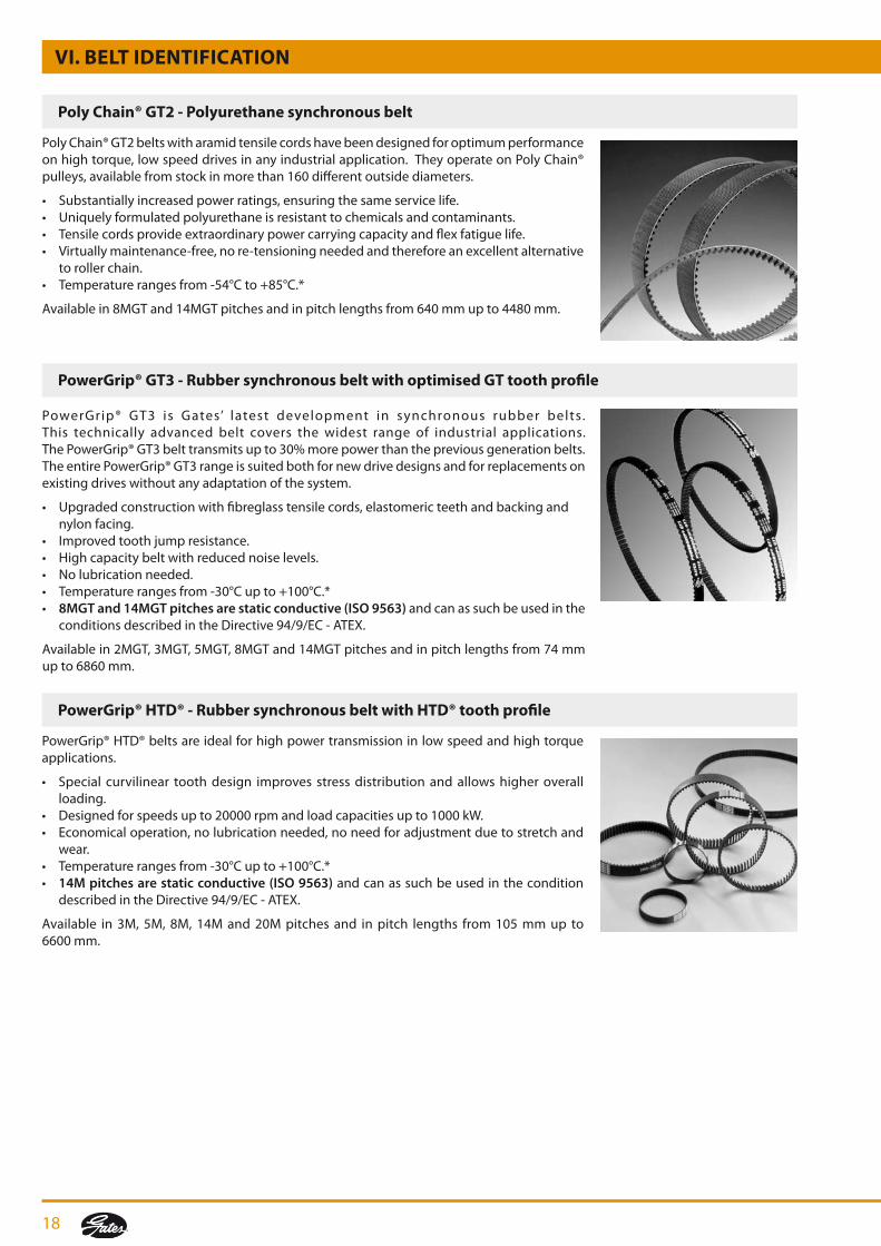
GatesPredator®V-beltsarethemarkets’leadingV-belts.Uniqueintheirextremerobustnessandhighloadcarryingcapabilitytheyareunrivalled.TheyareexcellentproblemsolversthatperformwellinharshenvironmentsandinextremelydemandingapplicationswherestandardV-belts have performance issues.
• Atleast40%higherpowerratingsthanstandardconstructionV-belts.• Chloroprenerubbercompoundsprovidesuperboilandheatresistance.• Doublefabriccoveroffersextremeabrasionandwearresistance.• Speciallytreatedextratoughcoverwithstandsslipandshearforcesatpeakloadswithout
generatingexcessiveheatandresistspenetrationbyforeignmaterials.• Non-rubbersurfacedcoverallowsmomentaryslippageduetoexcessiveoverloadswithout
damaging the belt.• Aramidtensilecordsprovideextraordinarystrength,durabilityandvirtuallyzerostretch.• Predator®singlebeltsareavailableondemandinAP,BP,CP,SPBP,SPCPand8VPsectionsin
lengthsover1,400mm.TheyarespeciallydesignedforapplicationswherePowerBand®beltsare not an option, e.g. where debris needs to pass through the space between individual belts without damaging the belt section.
• Temperaturerangesfrom-30°Cupto+60°C.*• Predator®PowerBand®beltsarestatic conductive (ISO 1813)(exceptfor8VP)andcanas
suchbeusedintheconditionsdescribedintheDirective94/9/EC–ATEX;fordetailedinfoonthestaticconductivityofPredator®singlebelts,pleasecontactyourGatesrepresentative.
Available in SPBP, SPCP, 9JP, 15JP and 8VP sections and in lengths from1400mmup to15240mm.
GatesQuad-Power®IIPowerBand®offersastablepositioninthepulleysandasmoothrunningsolution for drives where single belts vibrate.
• Strongbandcontrolsbelt-to-beltdistanceandpreventssidewaysbending.• Elastomericcompoundprotectsthebeltagainstheat,ozoneandsunlight.• Flatbackconstructionreducesnoisewhenusedwithabacksideidlerortensioner.• Flex-bonded tensile cordsmake thebelthighly resistant to tensile andflexing forces,
fatigueandshockloads.• Temperaturerangesfrom-30°Cupto+60°C.*• Match system: all sizesmeetGatesUNISET tolerances, they can be installed without
matching.• Static conductive (ISO 1813) and can as such be used in the conditions described in the
Directive94/9/EC–ATEX.
Available in XPZ, XPA, XPB, 3VX and 5VX sections and in lengths from 635mmup to5080mm.
Predator® PowerBand® - Wrapped, narrow section multiple V-belt
Quad-Power® II PowerBand® - raw edge, moulded notch, narrow section multiple V-belt

15
VI. BELt IdEntIfIcAtIon
Super hc® and hi-Power® PowerBand® - Wrapped, narrow section/classical section multiple V-belt
Powerated® - Green textile wrapped V-belt
GatesSuperHC®PowerBand®andHi-Power®PowerBand®offera solution fordriveswheresingle belts vibrate, turn over or jump of the pulleys.
• Strongbandcontrolsbelt-to-beltdistanceandpreventssidewaysbending.• Concavesidesandarchedtop.• Elastomericcompoundprotectsthebeltagainstheat,ozoneandsunlight.• Flex-Weave®coverprotectsthebeltcorefromthetoughestenvironments.• Flex-bondedtensilecordsmakethebelthighlyresistanttotensileandflexingforces,fatigue
andshockloads.• Temperaturerangesfrom-30°Cupto+60°C.*• Static conductive (ISO 1813) and can as such be used in the conditions described in the
Directive94/9/EC–ATEX.
SuperHC®PowerBand®beltsareavailableinSPB,SPC,9J/3V,15J/5Vand25J/8Vsectionsandinlengthsfrom1250mmupto15240mm.Hi-Power®PowerBand®beltsareavailableinB,CandDsectionsandinlengthsfrom935mmupto16784mm.
PoweRated®V-beltshaveahigherpowercapacitythanconventionallight-dutybelts.Theyareidealforheavyshockloadedandbackidlerdrivenlawnandgardenequipment.
• Strongaramidtensilecords.• Cordreinforcementandlowfrictionwrappingimproveclutchingoperation.• Temperaturerangesfrom-30°Cupto+60°C.*
Availablein3L,4Land5Lsectionsandinoutsidelengthsfrom406mmupto2515mm.
Multi-Speed™ - Wide raw edge V-belt
The Multi-Speed™ V-belt for variable speed drives adjusts itself automatically to the pulley groove providing a wide range of speeds and speed ratios.
• Highload-carryingcapacity.• Notchingincreasesflexibilityandensuresmaximumheatdispersion.• Strongtransverserigidity.• Uniformundercordthicknessensuressmoothrunning.• Temperaturerangesfrom-30°Cupto+60°C.*
AvailableinISOprofileswithlengthsfrom630mmupto3150mm.AdditionalGateslinecoversthe most popular applications.

16
IndustrialMicro-V®beltsfeaturetruncatedV-ribswhichincreaseflexibility,reduceheatbuild-upandimprovecrackresistance.Thisuniquedesignletsthebeltperformatextrahighspeedson smaller diameter pulleys.
• Thetruncateddesignstandsfor:apowercapacity increaseupto80%higherthanRMAstandards, better tolerance of debris in the pulley groove.
• Polyestertensilememberprovidessuperiorresistancetofatigueandshockloads.• Highlyresistanttooilandheat.• Temperaturerangesfrom-30°Cupto+60°C.*• Static conductive (ISO 1813) and can as such be used in the conditions described in
theDirective94/9/EC–ATEX.
Available in PJ, PL and PM sections and in effective lengths from 406 mm up to 9931 mm.SlabsinPKsectionupto2500mmareavailableonrequest.
Polyflex® and Polyflex® JB™ - Polyurethane V-belt/multiple V-belt
BecauseoftheirsmallsectionsPolyflex®beltsare ideal forcompactshortcentreandsmalldiameterdrives.Polyflex®JB™multipleV-beltsaswellasPolyflex®singlebeltscanoperateatveryhighshaftspeedsupto30000rpm.
• Polyurethanecompoundwithhighfrictioncoefficientcastasasingleunitaftertensilecordsare positioned in the mould.
• 60°anglebettersupportsthetensilesectionprovidingevenloaddistribution.• Polyflex®JB™joinedbeltconstructionimprovesstability.• Temperaturerangesfrom-54°Cupto+85°C.*
Polyflex®JB™multipleV-beltsareavailablein3M-JB,5M-JB,7M-JBand11M-JBsectionsandineffectivelengthsfrom175mmupto2293mm.Polyflex®singlebeltsareavailablein3M,5M,7Mand11Msectionsandineffectivelengthsfrom180mmupto2300mm.
Micro-V® - Multi-ribbed V-belt
VI. BELt IdEntIfIcAtIon
* NOTE Forapplicationsoutsidethisrange,pleaseconsultyourGatesrepresentative.

17
VI. BELt IdEntIfIcAtIon
Synchronous belts
Poly chain® Gt carbon™ - Polyurethane synchronous belt with patented carbon tensile cords
Synchronous belts are identified by:1. Belt pitch: distance (mm) between two adjacent tooth centres as measured on the belt’s pitch line.2. Belt pitch length: circumference (mm) as measured along the pitch line.3. Width: top width (mm).4. tooth profile:seepages25-27fortheeasiestwaytoidentifythis.
Synchronous belts run on pulleys, which are specified by the following:1. Pitch: distance (mm) between groove centres, measured on the pulley pitch circle. The pitch circle coincides with the pitch line of the mating belt.2. number of pulley grooves.3. Width: face width.
notE: - The pulley’s pitch diameter is always greater than its outside diameter. - Also note that the belt tooth and pulley grooves should always be of the same profile (shape).
Never interchange pulley and tooth types!
PolyChain®GTCarbon™isGates’newpolyurethanesynchronousbeltwithpatentedcarbontensilecorddesignedforhightorque,lowspeeddrives.Thematerialsdevelopmentengineers from Gates are the first to have incorporated a high fatigue-resisting carbon fibre tensilecordintothebeltwhichismadeofanewpolyurethanecompound.Consequently,PolyChain®GTCarbon™isthemostpowerfulsynchronousbeltinthemarketprovidingamaintenance-free, energy saving and environmentally friendly operation.
• Highestpowercapacity:atleast25%higherpowerratingsthanPolyChain®GT2belts.• Thebasicbeltconsistsofanewlydeveloped,lightweightpolyurethanecompoundwhich
is chemically resistant and ensures optimum adhesion with the carbon tensile cords.• Thecarbontensilecordsprovidehigherpowerratings,highstrength,improvedfatigueand
shock load resistance, increasedflexibility,excellent reversebendingstress,high lengthstabilityandvirtuallyzerostretch.
• Availablein8MGTand14MGTpitchesoperatingonexistingPolyChain®pulleys.• Clean,quiet, compact,durable,maintenance-free, energy savingandenvironmentally
friendly operation.• Unparalleledsavingsinweight,spaceandmoney.• Temperaturerangesfrom-54°Cto+85°C.*• Now also available in 2 special belt constructions: - Poly Chain® GT Carbon™ High Temperature Special polyurethane compound provides superb heat resistance. It enables the
belttoremainfullyoperationalunderextremetemperaturesrangingupto120°C andevenupto140°Cduringshorterperiods;
- Poly Chain® GT Carbon™ Hot Oil Special polyurethane compound provides superb oil and heat resistance, ensuring
aproblem-freeoperationinoilenvironmentsattemperaturesrangingupto120°C (suitablefortransfercases,gearboxes…).
Availablein8MGTand14MGTpitchesandinpitchlengthsfrom640mmupto4480mm.AlsoavailableinMiniPolyChain®GTCarbon™withGTteethin8Mpitchandinpitchlengthsfrom248mmupto608mm.PolyChain®GT™CarbonHighTemperatureandPolyChain®GT™CarbonHotOilareavailableinstandardlengthsupto2000mm.Thebeltsareonlyavailableonrequest.Formoredetailedinformation and correct usage, please contact your Gates representative.
18
Poly chain® Gt2 - Polyurethane synchronous belt
PowerGrip® Gt3 - rubber synchronous belt with optimised Gt tooth profile
VI. BELt IdEntIfIcAtIon
PolyChain®GT2beltswitharamidtensilecordshavebeendesignedforoptimumperformanceonhightorque,lowspeeddrivesinanyindustrialapplication.TheyoperateonPolyChain®pulleys,availablefromstockinmorethan160differentoutsidediameters.
• Substantiallyincreasedpowerratings,ensuringthesameservicelife.• Uniquelyformulatedpolyurethaneisresistanttochemicalsandcontaminants.• Tensilecordsprovideextraordinarypowercarryingcapacityandflexfatiguelife.• Virtuallymaintenance-free,nore-tensioningneededandthereforeanexcellentalternative
to roller chain.• Temperaturerangesfrom-54°Cto+85°C.*
Availablein8MGTand14MGTpitchesandinpitchlengthsfrom640mmupto4480mm.
PowerGrip® GT3 is Gates’ latest development in synchronous rubber belts.This technically advanced belt covers the widest range of industrial applications. ThePowerGrip®GT3belttransmitsupto30%morepowerthanthepreviousgenerationbelts.TheentirePowerGrip®GT3rangeissuitedbothfornewdrivedesignsandforreplacementsonexistingdriveswithoutanyadaptationofthesystem.
• Upgradedconstructionwithfibreglasstensilecords,elastomericteethandbackingandnylon facing.
• Improvedtoothjumpresistance.• Highcapacitybeltwithreducednoiselevels.• Nolubricationneeded.• Temperaturerangesfrom-30°Cupto+100°C.*• 8MGT and 14MGT pitches are static conductive (ISO 9563) and can as such be used in the
conditionsdescribedintheDirective94/9/EC-ATEX.
Availablein2MGT,3MGT,5MGT,8MGTand14MGTpitchesandinpitchlengthsfrom74mmupto6860mm.
PowerGrip® htd® - rubber synchronous belt with htd® tooth profile
PowerGrip®HTD®beltsareidealforhighpowertransmissioninlowspeedandhightorqueapplications.
• Special curvilinear toothdesign improves stressdistributionandallowshigheroverallloading.
• Designedforspeedsupto20000rpmandloadcapacitiesupto1000kW.• Economicaloperation,nolubricationneeded,noneedforadjustmentduetostretchand
wear.• Temperaturerangesfrom-30°Cupto+100°C.*• 14M pitches are static conductive (ISO 9563) and can as such be used in the condition
describedintheDirective94/9/EC-ATEX.
Available in3M,5M,8M,14Mand20Mpitchesand inpitch lengths from105mmup to 6600mm.

19
VI. BELt IdEntIfIcAtIon
PowerGrip® ctB - classical synchronous belt
Long Length - open-end synchronous belt
ThePowerGrip®classicalsynchronousbeltoffersamaintenance-freeandeconomicalalternativetoconventionaldriveslikechainsandgears.
• Powertransmissionofupto150kWandspeedsofupto10000rpm.• Efficienciesupto99%.• Widerangeofloadcapacitiesandspeedratios.• Temperaturerangesfrom-30°Cupto+100°C.*
AvailableinstandardMXL(0.08inches),XL,L,H,XHandXXHpitchesaccordingtoISO5296andinpitchlengthsfrom73mmupto4572mm.
Long Length belts are especially suited for linear movements (automated doors, warehouse conveyorsandelevators),accuratepositioning(machinetools,x-yco-ordinatemachines)andreversaldrives(computers,printersandofficeequipment).
• Highpowertransmissionandhighpositioningaccuracy.• Lengthstabilitythankstohighmodulustensilemembers.• Easytoattachwithclampingfixtures.• Temperaturerangesfrom-30°Cupto+100°C.*
Available pitches and lengths:Elastomericcompound:PowerGrip®XL,L,H;HTD®3M,5M,8M&14M;GT3MR,5MR&8MR(30mlengths);Polyurethanecompound:PolyChain®GTCarbon™8MGT&14MGT(30mlengths).
twin Power® - double-sided synchronous belt
Dueto itsdoubleanddirectlyopposite teeth,TwinPower® synchronousbeltsensurehighloadingcapacityoncontra-rotatingdrivesandensuresmoothrunningandhighflexibility.
• Transmissionof100%ofitsmaximumratedloadfromeithersideofthebelt.Alternatively,itcantransmita loadonbothsidesprovidedthesumofthe loadsdoesnotexceedthemaximumcapacity.
• AvailablewiththeclassicaltrapezoidalbutalsowithHTD®oruniqueGTtoothprofile.• Temperaturerangesfrom-30°Cupto+100°C.*
AvailableinPowerGrip®GT28MGTand14MGTandpitchlengthsfrom480mmupto6860mm;PowerGrip®HTD®5Mandpitchlengthsfrom425mmupto2525mm;PowerGrip®XL,LandHandpitchlengthsfrom381mmupto4318mm.
LiftPower™ - open-end flat belt
LiftPower™ belts have been designed for optimum performance on lifting and handling applications tomoveplatformsand/orweights. Theyarean idealalternative tohydrauliccylinders in scissors-type lifting tables and to chains and steel cables in vertical transport of motor vehicles in high rise stores. LiftPower™ belts run on flat pulleys.
• Useofsteelcordsorhighperformancesteelcordsresultsinverylowelongationandincreasedflexibilitycomparedtosteelcables.
• Smooth-runningandhigherspeedscomparedtochainsandsteelcables.• Reducednoiselevel.• Fabriconthebackofthebeltensureslessfrictionandhighwearresistance.• Temperaturerangesfrom-30°Cupto+100°C.*
Availableondemandonrollsof100m.

20
transMotion™ - rubber synchronous belt with conveyor cord
TransMotion™ is themostpowerful rubberbelt in themarket for conveyor applications.TransMotion™guaranteesa100%reliabilitywhen it isused forconveyer lines in themostdiverse industries.
• Technicallyadvancedcompoundwithelastomericteethandbackingandnylonfacing.• Conveyorcordprovidessuperiortoothjumpresistanceandshockloadresistance.Allows
use in wash down applications.• Static conductive (ISO 9563) and can as such be used in the conditions described in the
Directive94/9/EC–ATEX.• Temperaturerangesfrom-30°Cupto+100°C.*
Availablein8MGTpitchandinpitchlengthsfrom384mmupto4400mm.
trAnSMotIon™ - courroie synchrone en caoutchouc avec une corde de convoyagePowerPaint™ - Paint and varnish compatible synchronous belt
PowerPainT™ synchronous belt is specifically developed for use in painting areas, as found in the automotive and white goods industries where contamination of the painted product, from whatever source, is unacceptable.
• Precision-formedelastomericteethwithcurvilinearprofileimprovestressdistributionandprovide high power capacity.
• Accuratelyspacedteethprovidehighpositioningaccuracyandoptimumefficiency.• Toughtensilecordsensureexcellentflexlifeandhighresistancetoelongation.• Temperaturerangesfrom-30°Cupto+100°C.*
Available pitches:PolyChain®GTCarbon™8MGT&14MGT;PolyChain®GT28MGT&14MGT;PowerGrip®GT35MGT,8MGT&14MGT;PowerGrip®HTD®3M,5M,8M&14M;TransMotion™8MGT;LongLengthPowerGrip®GT3MR,5MR&8MR;LongLengthPowerGrip®HTD®3M,5M,8M&14M;LongLengthPowerGrip®XL,L&HandLongLengthPolyChain®8MGT&14MGT.
trAnSMotIon™ - courroie synchrone en caoutchouc avec une corde de convoyageSynchro-Power® - open-end/endless polyurethane synchronous belt
GatesSynchro-Power®polyurethanebeltsprovidemaximumpowertransmissioncombinedwithperfecttoothmeshingandtightandaccuratetolerances.Polyurethaneisextremelywearandfatigueresistantandatthesametimehighlyflexible.GatesSynchro-Power®beltsarebothavailable as endless and as open-end belt and can be used in a wide variety of applications in theprintingindustry,textileindustry,foodindustryetc.GatesSynchro-Power®bluesleevesarethemostrecentadditiontothePUrange.Theyareavailableupto200mmwidthandcaneasily be recognised by their blue colour.
•Toughandflexiblepolyurethanecompoundofconsistentquality.•Resistancetoelongation,wearandfatigue.•Widerangeoftoothprofilestomeetinnumerableapplicationrequirements.•Synchro-Power®isavailablein: - Synchro-Power®sleeves,whicharetrulyendlessandhavenojoint,aresupplied
with steel tensile cords. - Synchro-Power®LongLengthbelts,whicharemanufacturedasopen-endextruded
belts, are supplied with steel, stainless steel or aramid tensile cords, depending on the belt construction.
•Temperaturerangesfrom-5°Cupto+70°C.*
PleaserefertotheGatesIndustrialBeltCatalogue(ref.E2/20054)forspecifics,orconsultyourGates representative for more information.
VI. BELt IdEntIfIcAtIon
transMotion™ - rubber synchronous belt with conveyor cord
* NOTE Forapplicationsoutsidethisrange,pleaseconsultyourGatesrepresentative.

21
EuroGrip® coupling
flexible couplings
EuroGrip®flexiblecouplingsfeatureOGEElinesallowingthecouplingtoactasatorque/life indicatorforthedrive,andahighdampingcapacity,whichmakesthemespeciallysuitable for direct drive applications in pumps and compressors.
• Sleevesofhigh-performanceelastomericcompound.• Endpiecesofhigh-gradealuminiumreduceweightandinertia.Availableeitherwith
finishedboreandkeywayortosuitataperbush.• Zerobacklashresultsinhighpositioningaccuracy.• Highvibrationdamping.• Quietinoperation.• Hightoleranceofcombinationsofradialandangularmisalignment.• Temperaturerangesfrom-25°Cupto+100°C.
Availableinsizes19,28,42,48and60andboredtosuittaperbushoraplainboreandkeyway.
Fordetailedsleeveandend-piecedimensionsofEuroGrip®couplings,pleaseseecatalogueE2/20103.
VI. BELt IdEntIfIcAtIon

22
VI. BELt IdEntIfIcAtIon
2. Sections and nominal dimensions: V-belts
Quad-Power® IIRaw edge, moulded notch, narrow section V-belt
Super hc® Wrapped, narrow section V-belt
Super hc® MnRaw edge, moulded notch, narrow section V-belt
WIDTH HEIGHT
mm mm
XPZ/3VX 10 8
XPA 13 10
XPB/5VX 16 13
XPc 22 18
WIDTH HEIGHT
mm mm
SPZ/3V 10 8
SPA 13 10
SPB/5V 16 13
SPc 22 18
8V 26 23
WIDTH HEIGHT
mm mm
SPZ-Mn/ 3VX 10 8
SPA-Mn 13 10
SPB-Mn/ 5VX 16 13
SPc-Mn 22 18
Predator®Wrapped,narrowsection/classicalsectionV-belt
WIDTH HEIGHT
mm mm
AP 13 8
BP 17 11
cP 22 14
SPBP 16 13
SPcP 22 18
8VP 26 23

23
VI. BELt IdEntIfIcAtIon
Predator® PowerBand®Wrapped, narrow section multiple V-belt
WIDTH HEIGHT PITCH
mm mm mm
SPBP 16 13 19.00
SPcP 22 18 25.50
9JP/3VP 10 8 10.30
15JP/5VP 16 13 17.50
25JP/8VP 26 23 28.60
VulcoPlus™Wrapped, narrow section V-belt
WIDTH HEIGHT
mm mm
SPZ/3V 10 8
SPA 13 10
SPB/5V 16 13
SPc 22 18
VulcoPower™Wrapped, classical section V-belt
WIDTH HEIGHT
mm mm
Z 10 6
A 13 8
B 17 11
c 22 14
hi-Power®Wrapped, classical section V-belt
WIDTH HEIGHT
mm mm
Z 10 6
A 13 8
B 17 11
c 22 14
d 32 19
Quad-Power® II PowerBand®Raw edge, moulded notch, narrow section multiple V-belt
WIDTH HEIGHT PITCH
mm mm mm
XPZ 10 8 12.00
XPA 13 10 15.00
XPB 16 13 19.00
3VX 10 8 10.30
5VX 16 13 17.50

24
WIDTH HEIGHT
inch inch
3L 3/8 7/32
4L 1/2 5/16
5L 21/32 3/8
Powerated®Wrapped,greentextileV-belt
Polyflex® JB™Polyurethane multiple V-belt
Micro-V®Multi-ribbed V-belt
Polyflex® Polyurethane V-belt
Super hc® and hi-Power® PowerBand®Wrapped,narrowsection/classicalsectionmultipleV-belt
WIDTH HEIGHT PITCH
mm mm mm
3M-JB 3 2.28 3.35
5M-JB 5 3.30 5.30
7M-JB 7 5.33 8.50
11M-JB 11 7.06 13.20
HEIGHT PITCH
mm mm
PJ 3.50 2.34 Pk 4.45 3.56
PL 9.50 4.70
PM 16.50 9.40
WIDTH HEIGHT
mm mm
3M 3 2.28
5M 5 3.30
7M 7 5.33
11M 11 6.85
WIDTH HEIGHT PITCH
mm mm mm
SPB 16 13 19.00
SPc 22 18 25.50
9J/3V 10 8 10.30
15J/5V 16 13 17.50
25J/8V 26 23 28.60
B 17 10 19.05
c 22 12 25.40
d 32 19 36.50
VI. BELt IdEntIfIcAtIon

25
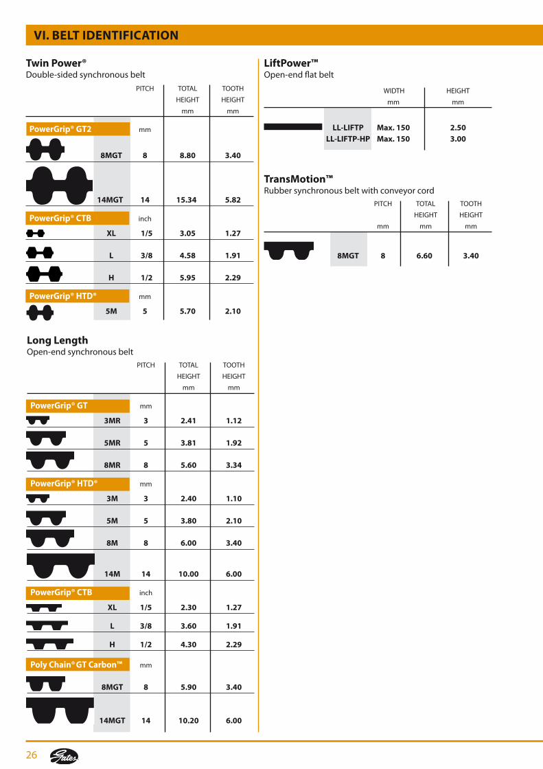
PowerGrip® CTBClassical synchronous belt PITCH TOTAL TOOTH
HEIGHT HEIGHT
inch mm mm
MXL 0.08 1.14 0.51
XL 1/5 2.30 1.27
L 3/8 3.50 1.91
H 1/2 4.00 2.29
XH 7/8 11.40 6.36
XXH 1 1/4 15.20 9.53
3. Sections and nominal dimensions: synchronous belts
PowerGrip® HTD®Rubber synchronous belt wit HTD® tooth profile
PITCH TOTAL TOOTH
HEIGHT HEIGHT
mm mm mm
3M 3 2.40 1.20
5M 5 3.80 2.10
8M 8 6.00 3.40
14M 14 10.00 6.10
20M 20 13.20 8.40
PowerGrip® GT3Rubber synchronous belt with optimised GT tooth profile
PITCH TOTAL TOOTH
HEIGHT HEIGHT
mm mm mm
2MGT 2 1.52 0.71
3MGT 3 2.41 1.12
5MGT 5 3.81 1.92
8MGT 8 5.60 3.40
14MGT 14 10.00 6.00
VI. BeLT IDenTIfICaTIon
Poly Chain® GT Carbon™Polyurethane synchronous belt with patented carbon tensile cords
PITCH TOTAL TOOTH
HEIGHT HEIGHT
mm mm mm
8MGT 8 5.90 3.40
14MGT 14 10.20 6.00
Poly Chain® GT2Polyurethane synchronous belt
PITCH TOTAL TOOTH
HEIGHT HEIGHT
mm mm mm
8MGT 8 5.90 3.40
14MGT 14 10.20 6.00
26
VI. BeLT IDenTIfICaTIon
Long LengthOpen-end synchronous belt PITCH TOTAL TOOTH
HEIGHT HEIGHT
mm mm
PowerGrip® GT mm
3MR 3 2.41 1.12
5MR 5 3.81 1.92
8MR 8 5.60 3.34
PowerGrip® HTD® mm
3M 3 2.40 1.10
5M 5 3.80 2.10
8M 8 6.00 3.40
14M 14 10.00 6.00
PowerGrip® CTB inch
XL 1/5 2.30 1.27
L 3/8 3.60 1.91
H 1/2 4.30 2.29
Poly Chain® GT Carbon™ mm
8MGT 8 5.90 3.40
14MGT 14 10.20 6.00
Twin Power®Double-sided synchronous belt
PITCH TOTAL TOOTH
HEIGHT HEIGHT
mm mm mm
8MGT 8 6.60 3.40
TransMotion™Rubber synchronous belt with conveyor cord
PITCH TOTAL TOOTH
HEIGHT HEIGHT
mm mm
PowerGrip® GT2 mm
8MGT 8 8.80 3.40
14MGT 14 15.34 5.82
PowerGrip® CTB inch
XL 1/5 3.05 1.27
L 3/8 4.58 1.91
H 1/2 5.95 2.29
PowerGrip® HTD® mm
5M 5 5.70 2.10
LiftPower™Open-end flat belt
WIDTH HEIGHT
mm mm
LL-LIfTP Max. 150 2.50 LL-LIfTP-HP Max. 150 3.00
27
T
B
T
TB
TB
TB
B
BT
BT
BT
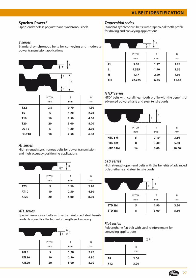
t2.5 2.5 0.70 1.30
t5 5 1.20 2.20
t10 10 2.50 4.50
t20 20 5.00 8.00
dL-t5 5 1.20 3.30
dL-t10 10 2.50 6.80
XL 5.08 1.27 2.29
L 9.525 1.90 3.56
h 12.7 2.29 4.06
Xh 22.225 6.35 11.18
At5 5 1.20 2.70
At10 10 2.50 4.50
At20 20 5.00 8.00
htd 5M 5 2.10 3.60
htd 8M 8 3.40 5.60
htd 14M 14 6.00 10.00
Std 5M 5 1.90 3.30
Std 8M 8 3.00 5.10
f8 2.00
f12 3.20
AtL5 5 1.20 2.70
AtL10 10 2.50 4.80
AtL20 20 5.00 8.00
Synchro-Power® Open-end/endlesspolyurethanesynchronousbelt
T seriesStandard synchronous belts for conveying and moderate power transmission applications
Trapezoidal seriesStandardsynchronousbeltswithtrapezoidaltoothprofilefor driving and conveying applications
AT seriesHigh strength synchronous belts for power transmission and high accuracy positioning applications
HTD® seriesHTD®beltswithcurvilineartoothprofilewiththebenefitsofadvanced polyurethane and steel tensile cords
ATL seriesSpecial lineardrivebeltswithextra reinforcedsteel tensilecords designed for the highest strength and accuracy
STD seriesHigh strength open-end belts with the benefits of advanced polyurethane and steel tensile cords
Flat seriesPolyurethane flat belt with steel reinforcement for conveying applications
PITCH
mm
T
mm
B
mm
PITCH
mm
T
mm
B
mm
PITCH
mm
T
mm
B
mm
PITCH
mm
T
mm
B
mm
PITCH
mm
T
mm
B
mm
PITCH
mm
T
mm
B
mm
B
mm
VI. BELt IdEntIfIcAtIon
28
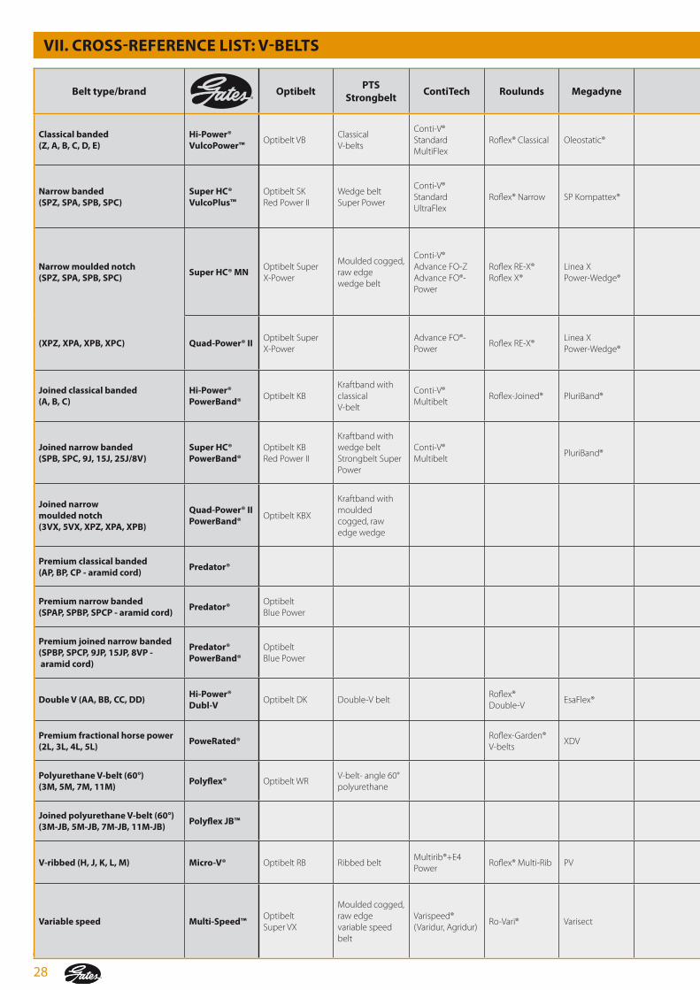
VII. croSS-rEfErEncE LISt: V-BELtS
Belt type/brand optibeltPtS
Strongbeltcontitech roulunds Megadyne Stomil Skf
colmant cuvelier
fenner Pix Goodyear Bando Mitsuboshi
classical banded (Z, A, B, c, d, E)
hi-Power® VulcoPower™
Optibelt VBClassical V-belts
Conti-V®Standard MultiFlex
Roflex® Classical Oleostatic® Classic V-beltWrapped classical belt
Veco 100®Fenner® ClassicPB V-Belts
Power Wrap Torque-Flex® V Classical V-belt Conventional
narrow banded (SPZ, SPA, SPB, SPc)
Super hc® VulcoPlus™
Optibelt SK Red Power II
Wedge belt Super Power
Conti-V® Standard UltraFlex
Roflex® Narrow SP Kompattex® Narrow V-belt
Wrapped wedge belt Wrapped narrow wedge
Veco 200®Fenner® PowerPlus® wedgebelt
Power WrapNarrow SP Power Ace®
Maxstar wedge
narrow moulded notch (SPZ, SPA, SPB, SPc)
Super hc® MnOptibelt Super X-Power
Moulded cogged, raw edge wedge belt
Conti-V® Advance FO-ZAdvance FO®-Power
Roflex RE-X® Roflex X®
Linea X Power-Wedge®
Cogged raw edge wedge belt
Veco GTX
Fenner® CRE PLUS® wedge belt Fenner® Quattro PLUS® belt
Power EdgeTorque Flex® WedgeHy-T® Wedge
Power Ace® CogNarrow SPX
Maxstar wedge supreme
(XPZ, XPA, XPB, XPc) Quad-Power® IIOptibelt Super X-Power
Advance FO®-Power
Roflex RE-X®Linea X Power-Wedge®
Fenner® Quattro PLUS® belt
Joined classical banded (A, B, c)
hi-Power® PowerBand®
Optibelt KBKraftband with classical V-belt
Conti-V® Multibelt
Roflex-Joined® PluriBand® Joined bandedBanded classical belt
Power BankHy-T® Torque Team® Plus
Power King® ComboPower Scrum
Conventional Banded
Joined narrow banded (SPB, SPc, 9J, 15J, 25J/8V)
Super hc® PowerBand®
Optibelt KB Red Power II
Kraftband with wedge belt Strongbelt Super Power
Conti-V® Multibelt
PluriBand® Joined bandedBanded wedge belt
Vecoband®Fenner® Concord Plus®
Power BankHy-T® Torque Team® Wedge
Power Ace® Combo
Multi Maxstar
Joined narrow moulded notch (3VX, 5VX, XPZ, XPA, XPB)
Quad-Power® II PowerBand®
Optibelt KBX
Kraftband with moulded cogged, raw edge wedge
Hy-T® Torque Team® V
Power Ace® Cog Combo
Multi Maxstar
Premium classical banded (AP, BP, cP - aramid cord)
Predator®
Premium narrow banded (SPAP, SPBP, SPcP - aramid cord)
Predator®Optibelt Blue Power
Premium joined narrow banded (SPBP, SPcP, 9JP, 15JP, 8VP - aramid cord)
Predator® PowerBand®
Optibelt Blue Power
double V (AA, BB, cc, dd)hi-Power® dubl-V
Optibelt DK Double-V beltRoflex® Double-V
EsaFlex®Double side V-belt
Double classical (Hex) belt
Power Hex Hex belt Double V
Premium fractional horse power (2L, 3L, 4L, 5L)
Powerated®Roflex-Garden® V-belts
XDVPix Lawn & Garden
Insta-Power™ UltraPower AG
Polyurethane V-belt (60°) (3M, 5M, 7M, 11M)
Polyflex® Optibelt WRV-belt- angle 60° polyurethane
Neothane® Banflex Polymax
Joined polyurethane V-belt (60°) (3M-JB, 5M-JB, 7M-JB, 11M-JB)
Polyflex JB™ Banflex® Combo Multi Polymax
V-ribbed (h, J, k, L, M) Micro-V® Optibelt RB Ribbed beltMultirib®+E4 Power
Roflex® Multi-Rib PV Ribbed beltFenner® Poly DriveRibbed belts
Power Rib Poly-V Rib Ace® Ribstar
Variable speed Multi-Speed™Optibelt Super VX
Moulded cogged, raw edge variable speed belt
Varispeed® (Varidur, Agridur)
Ro-Vari® Varisect Wide V-belt Variveco Power Vari Variable Speed Power Max® Variable Speed

29
VII. croSS-rEfErEncE LISt: V-BELtS
Belt type/brand optibeltPtS
Strongbeltcontitech roulunds Megadyne Stomil Skf
colmant cuvelier
fenner Pix Goodyear Bando Mitsuboshi
classical banded (Z, A, B, c, d, E)
hi-Power® VulcoPower™
Optibelt VBClassical V-belts
Conti-V®Standard MultiFlex
Roflex® Classical Oleostatic® Classic V-beltWrapped classical belt
Veco 100®Fenner® ClassicPB V-Belts
Power Wrap Torque-Flex® V Classical V-belt Conventional
narrow banded (SPZ, SPA, SPB, SPc)
Super hc® VulcoPlus™
Optibelt SK Red Power II
Wedge belt Super Power
Conti-V® Standard UltraFlex
Roflex® Narrow SP Kompattex® Narrow V-belt
Wrapped wedge belt Wrapped narrow wedge
Veco 200®Fenner® PowerPlus® wedgebelt
Power WrapNarrow SP Power Ace®
Maxstar wedge
narrow moulded notch (SPZ, SPA, SPB, SPc)
Super hc® MnOptibelt Super X-Power
Moulded cogged, raw edge wedge belt
Conti-V® Advance FO-ZAdvance FO®-Power
Roflex RE-X® Roflex X®
Linea X Power-Wedge®
Cogged raw edge wedge belt
Veco GTX
Fenner® CRE PLUS® wedge belt Fenner® Quattro PLUS® belt
Power EdgeTorque Flex® WedgeHy-T® Wedge
Power Ace® CogNarrow SPX
Maxstar wedge supreme
(XPZ, XPA, XPB, XPc) Quad-Power® IIOptibelt Super X-Power
Advance FO®-Power
Roflex RE-X®Linea X Power-Wedge®
Fenner® Quattro PLUS® belt
Joined classical banded (A, B, c)
hi-Power® PowerBand®
Optibelt KBKraftband with classical V-belt
Conti-V® Multibelt
Roflex-Joined® PluriBand® Joined bandedBanded classical belt
Power BankHy-T® Torque Team® Plus
Power King® ComboPower Scrum
Conventional Banded
Joined narrow banded (SPB, SPc, 9J, 15J, 25J/8V)
Super hc® PowerBand®
Optibelt KB Red Power II
Kraftband with wedge belt Strongbelt Super Power
Conti-V® Multibelt
PluriBand® Joined bandedBanded wedge belt
Vecoband®Fenner® Concord Plus®
Power BankHy-T® Torque Team® Wedge
Power Ace® Combo
Multi Maxstar
Joined narrow moulded notch (3VX, 5VX, XPZ, XPA, XPB)
Quad-Power® II PowerBand®
Optibelt KBX
Kraftband with moulded cogged, raw edge wedge
Hy-T® Torque Team® V
Power Ace® Cog Combo
Multi Maxstar
Premium classical banded (AP, BP, cP - aramid cord)
Predator®
Premium narrow banded (SPAP, SPBP, SPcP - aramid cord)
Predator®Optibelt Blue Power
Premium joined narrow banded (SPBP, SPcP, 9JP, 15JP, 8VP - aramid cord)
Predator® PowerBand®
Optibelt Blue Power
double V (AA, BB, cc, dd)hi-Power® dubl-V
Optibelt DK Double-V beltRoflex® Double-V
EsaFlex®Double side V-belt
Double classical (Hex) belt
Power Hex Hex belt Double V
Premium fractional horse power (2L, 3L, 4L, 5L)
Powerated®Roflex-Garden® V-belts
XDVPix Lawn & Garden
Insta-Power™ UltraPower AG
Polyurethane V-belt (60°) (3M, 5M, 7M, 11M)
Polyflex® Optibelt WRV-belt- angle 60° polyurethane
Neothane® Banflex Polymax
Joined polyurethane V-belt (60°) (3M-JB, 5M-JB, 7M-JB, 11M-JB)
Polyflex JB™ Banflex® Combo Multi Polymax
V-ribbed (h, J, k, L, M) Micro-V® Optibelt RB Ribbed beltMultirib®+E4 Power
Roflex® Multi-Rib PV Ribbed beltFenner® Poly DriveRibbed belts
Power Rib Poly-V Rib Ace® Ribstar
Variable speed Multi-Speed™Optibelt Super VX
Moulded cogged, raw edge variable speed belt
Varispeed® (Varidur, Agridur)
Ro-Vari® Varisect Wide V-belt Variveco Power Vari Variable Speed Power Max® Variable Speed

30
VIII. croSS-rEfErEncE LISt: SynchronouS BELtS
Belt type/brand optibelt PtS Strongbelt contitech Megadyne Skfcolmant cuveliers
fenner Pix Goodyear Bando Mitsuboshi
trapezoidal (MXL, XL, L, h, Xh, XXh)
PowerGrip® ctB Optibelt ZR Timing belt - inch Synchrobelt® Isoran® Timing beltVeco® Synchro Standard
Fenner® Classical X' treme® Classical Positive Drive Pd™ Synchro-Link®Timing Belt GTiming Belt U
high torque (3 mm, 5 mm, 8 mm, 14 mm, 20 mm)
PowerGrip® htd®
Optibelt Omega Optibelt HTD®/STD®
Strongbelt MSynchrobelt® (HTD/STD)
RPP® HiTD Veco® Synchro HTB Fenner® HTD X' treme® HTDHi-Performance Pd™ Plus
Synchro-Link® STS
Increase power rating (2 mm, 3 mm, 5 mm, 8 mm, 14 mm)
PowerGrip® Gt3Optibelt Omega HP Optibelt Omega FanPower
Strongbelt PremiumSynchroforce® CXP (III) (HTD/STD)
RPP® PlusFenner® Torque Drive Plus®
SuperTorque Pd™
Increase power rating (2 mm, 3 mm, 5 mm, 8 mm, 14 mm)
PowerGrip® Gt3Synchroforce® Supreme
Increase power rating - improved cord (8 mm, 14 mm)
transMotion™ Optibelt Omega HL
Synchroforce® CXA(III) (HTD/STD) Synchroforce® Extreme
RPP® Gold RPPC Ultimate
Falcon HTC™
high performance, high torque (8 mm, 14 mm)
Poly chain® Gt2 SynchroChain® CTD
ultimate performance, unbeaten torque (8 mm, 14 mm)
Poly chain® Gt carbon™
double sided (XL, L, h, 3 mm, 5 mm, 8 mm, 14 mm)
twin Power® ctB twin Power® Gt2
Optibelt ZR-D Optibelt HTD®-D
Double Timing belt - MSynchroTwin® DH SynchroTwin® CXPIII
RPP® DD Isoran® DD
Double sided timing belt Double sided HiTD belt
Twin Power®Dual Positive Drive™Dual Hi-Performance PD™
Synchro-Link® double sided
open end - rubber Long Length Optibelt LinearOpen-ended timing belt
SynchroLine® Long Length® Open-end PD™ Open-end
Paint and varnish compatible PowerPaint™ Optibelt Rainbow Synchrocolor® MegaPaint®

31
VIII. croSS-rEfErEncE LISt: SynchronouS BELtS
Belt type/brand optibelt PtS Strongbelt contitech Megadyne Skfcolmant cuveliers
fenner Pix Goodyear Bando Mitsuboshi
trapezoidal (MXL, XL, L, h, Xh, XXh)
PowerGrip® ctB Optibelt ZR Timing belt - inch Synchrobelt® Isoran® Timing beltVeco® Synchro Standard
Fenner® Classical X' treme® Classical Positive Drive Pd™ Synchro-Link®Timing Belt GTiming Belt U
high torque (3 mm, 5 mm, 8 mm, 14 mm, 20 mm)
PowerGrip® htd®
Optibelt Omega Optibelt HTD®/STD®
Strongbelt MSynchrobelt® (HTD/STD)
RPP® HiTD Veco® Synchro HTB Fenner® HTD X' treme® HTDHi-Performance Pd™ Plus
Synchro-Link® STS
Increase power rating (2 mm, 3 mm, 5 mm, 8 mm, 14 mm)
PowerGrip® Gt3Optibelt Omega HP Optibelt Omega FanPower
Strongbelt PremiumSynchroforce® CXP (III) (HTD/STD)
RPP® PlusFenner® Torque Drive Plus®
SuperTorque Pd™
Increase power rating (2 mm, 3 mm, 5 mm, 8 mm, 14 mm)
PowerGrip® Gt3Synchroforce® Supreme
Increase power rating - improved cord (8 mm, 14 mm)
transMotion™ Optibelt Omega HL
Synchroforce® CXA(III) (HTD/STD) Synchroforce® Extreme
RPP® Gold RPPC Ultimate
Falcon HTC™
high performance, high torque (8 mm, 14 mm)
Poly chain® Gt2 SynchroChain® CTD
ultimate performance, unbeaten torque (8 mm, 14 mm)
Poly chain® Gt carbon™
double sided (XL, L, h, 3 mm, 5 mm, 8 mm, 14 mm)
twin Power® ctB twin Power® Gt2
Optibelt ZR-D Optibelt HTD®-D
Double Timing belt - MSynchroTwin® DH SynchroTwin® CXPIII
RPP® DD Isoran® DD
Double sided timing belt Double sided HiTD belt
Twin Power®Dual Positive Drive™Dual Hi-Performance PD™
Synchro-Link® double sided
open end - rubber Long Length Optibelt LinearOpen-ended timing belt
SynchroLine® Long Length® Open-end PD™ Open-end
Paint and varnish compatible PowerPaint™ Optibelt Rainbow Synchrocolor® MegaPaint®

32
IX. BELt drIVE PErforMAncE EVALuAtIon
to provide proper maintenance, you need to understand the nature of the belt drives in your plant.
Youknowtheexpectedbeltservicelifeofeachdrive.Andyouareawareofthecapabilitiesandlimitationsofthisequipment.Sometimes, however, it is necessary to give some thought to belt service life, especially on these occasions:
• Whenbeltservicelifeismeetingexpectations,butyouwouldliketoreduceexistingmaintenanceanddowntime;• Whenbeltservicelifeisbelowtheexpectedperformancelevelandthesituationmustbeimproved.
1. upgrading drive performanceA belt drive can sometimes be upgraded to improve performance. The first step is to see if simple improvements canbemadeatminimalcosts. This involveschecking thedrivedesignforadequatecapacity.
here are examples of minor changes that could improve performance:
• increasepulleydiameters;
• increasethenumberofbelts,orusewiderbelt;
• addvibrationdampeningtothesystem;
• improve guard ventilation to reduce operatingtemperature;
• makesurepulleyandbackidlerdiametersareabovetheminimumrecommendeddiameters;
• usepremiumbeltsratherthangeneralpurposetypes;
• replacewornpulleys;
• keeppulleysproperlyaligned;
• alwaysplaceidleronspanwithlowesttension;
• re-tensionnewlyinstalledfrictionbeltsaftera4-24hourrun-inperiod;
• review proper belt installation and maintenanceprocedures.
Iffurtherimprovementisneeded,thenextstepistoupgradethe drive to a higher performance belt system.
Gates is the recognised industry leader in product innovation and belt drive technology. New products and applications are continually made available to Gates customers.
Youmayhaveaproblemorexcessivemaintenancecostswitha non-belt drive, such as a gear or chain drive. Your local Gates representativecanofferyouexcellentadviceastowhetheror not a belt drive could solve the problem and reduce your maintenance costs.
Your local Gates distributor or representative can help you upgradeyourexistingdrivesandreduceyourmaintenanceand downtime costs.
2. Improving poor drive performanceIf your belt drive is correctly designed, installed and maintained, it will need very little attention. Occasionally, however,adrivemaybeaccidentallydamagedorknockedout of adjustment.
Changingoperatingrequirementsorenvironmentalconditionscan also create problems. The following troubleshooting guide is designed to help you identify and correct poor drive performance problems.

33
X. trouBLEShootInG GuIdE: V-BELtS
When troubleshooting a drive problem, your goal is to identify the cause(s) and then to take appropriate corrective action. the informa-tion in this section will help you put your drive back in operation.
Start by a description of the problem.
• Whatiswrong?• Whendidithappen?• Howoftendoesithappen?• Whatisthedriveapplication?• Havethemachineoperationsoroutputchanged?• Whatkind(s)ofbeltsareyouusing?• Whatareyourexpectationsforbeltperformance inthis
application?
Using the lists on thesepages, check theproblems youobserve. Thenmove to theproblem/cause/solution tableonpages34-40.
1. Problems on V-belt drives
unusual vibration• Beltsflapping• Excessivevibrationindrivesystem
Banded (joined) belt problems• Tie-bandseparation• Topoftie-bandfrayed,wornordamaged• PowerBand®comesoffdrive• Oneormorestrandsrunoutsideofpulley
Problems with pulleys• Brokenordamagedpulley• Severe,rapidgroovewear
Problems with drive components• Bentorbrokenshafts• Damagedguard
hot bearings• Beltovertensioned• Pulleystoosmall• Poorbearingcondition• Pulleystoofaroutonshaft• Beltslippage
Performance problems• IncorrectdriveNspeeds
Premature belt failure• Brokenbelt(s)• Belt(s)fail(s)tocarryload(slip),withoutvisiblereason• Edgecordfailure• Beltdelaminationorundercordseparation
Severe or abnormal belt wear• Wearonbelttopsurface• Wearonbelttopcorners• Wearonbeltsidewalls• Wearonbeltbottomcorners• Wearonbeltbottomsurface• Undercordcracking• Burnorhardeningonbottomorsidewall• Extensivehardeningofbeltexterior• Beltsurfaceflaking,stickyorswollen
V-belts turn over or come off drive• Singlebelt• Oneormorebeltsinaset• Joinedorbandedbelts
Belt stretches beyond available takeup• Singlebelt• Multiplebeltsstretchunequally• Allbeltsstretchequally
Belt noise• Squealor“chirp”• Slappingnoise• Rubbingsound• Grindingsound• Unusuallylouddrive

34
2. Problem/cause/solution table
SoLutIonProBABLE cAuSESyMPtoMS
SEV
ErE
or
AB
no
rM
AL
BEL
t W
EAr
Pr
EMA
tur
E B
ELt
fAIL
ur
E
Brokenbelt(s) 1. Underdesigneddrive 1. RedesignusingGatesDrive DesignManual(E2/20070). 2. Beltrolledorprisedontopulley 2. Usedrivetakeupwheninstalling. 3. Objectfallingintodrive 3. Provideadequateguardordrive protection. 4. Severeshockload 4. Redesigntoaccomodateshockload.
Beltfailstocarryload(slip); 1. Underdesigneddrive 1. RedesignusingGatesDrive novisiblereason DesignManual(E2/20070). 2. Damagedtensilemember 2.Followcorrectinstallation procedure. 3. Wornpulleygrooves 3.Checkforgroovewear, replace as needed. 4. Centredistancemovement 4. Checkdriveforcentredistance movement during operation.
Edgecordfailure 1. Pulleymisalignment 1. Checkandcorrectalignment. 2. Damagedtensilemember 2. Followinstallationprocedure.
Beltdelaminationorundercord 1. Pulleystoosmall 1. Checkdrivedesign,replacewith separation larger pulleys. 2. Backidlertoosmall 2. Increasebackidlertoacceptable diameter.
Wear on belt top surface 1. Rubbing against guard 1. Replace or repair guard. 2. Idler malfunction 2. Replace idler.
Wear on belt top corner 1. Belt-to-pulley fit incorrect 1. Use correct belt-to-pulley (belt too small for groove) combination.
Wear on belt sidewalls 1. Belt slip 1. Retension until slipping stops. 2. Misalignment 2. Realign pulleys. 3. Worn pulleys 3. Replace pulleys. 4. Incorrectbelt 4. Replacewithcorrectbeltsize.
Wear on belt bottom corners 1. Belt-to-pulley fit incorrect 1. Use correct belt-to-pulley combination. 2. Worn pulleys 2. Replace pulleys.
Wearonbeltbottomsurface 1. Beltbottomingonpulleygroove 1. Usecorrectbelt/pulleymatch. 2. Worn pulleys 2. Replace pulleys. 3. Debrisinpulleys 3. Cleanpulleys.
Undercordcracking 1. Pulleydiametertoosmall 1. Uselargerdiameterpulleys. 2. Belt slip 2. Retension. 3. Backidlertoosmall 3. Uselargerdiameterbackidler. 4. Improperstorage 4. Donotcoilbelttootightly,kinkor bend. Avoid heat and direct sunlight.
X. trouBLEShootInG GuIdE: V-BELtS

35
SoLutIonProBABLE cAuSESyMPtoMSV
-BEL
tS t
ur
n o
VEr
or
c
oM
E o
ff d
rIV
EB
ELt
Str
Etc
hES
BEy
on
d
AV
AIL
AB
LE t
Ak
EuP
SEV
ErE
or
AB
no
rM
AL
BEL
t W
EAr
BEL
t n
oIS
E
Burn or hardening on bottom or 1. Belt slip 1. Retension until slipping stops.sidewall 2. Worn pulleys 2. Replace pulleys. 3. Underdesigned drive 3. Redesign using Gates Drive DesignManual(E2/20070). 4.Shaftmovement 4. Checkforcentredistancechanges.
Extensivehardeningofbeltexterior 1. Hotdriveenvironment 1. Improveventilationtodrive.
Beltsurfaceflaking,stickyorswollen 1. Oilorchemicalcontamination 1. Donotusebeltdressing.Eliminate sources of oil, grease or chemical contamination.
Involvessingleormultiplebelts 1. Shockloadingorvibration 1. Checkdrivedesign.UseGates PowerBand®belts. 2. Foreignmaterialingrooves 2. Shieldgroovesanddrive. 3. Misaligned pulleys 3. Realign pulleys. 4. Worn pulley grooves 4. Replace pulleys. 5. Damagedtensilemember 5. Usecorrectinstallationandbelt storage procedure. 6. Incorrectlyplacedflatidlerpulley 6. Carefullyplaceflatidleronslack side of drive as close as possible to driveR pulleys. 7. Mismatched belt set 7. Replace with new set of matched belts.Donotmixoldandnewbelts. 8. Poordrivedesign 8. Checkforcentredistancestability and vibration dampening.
Multiplebeltsstretchunequally 1. Misaligneddrive 1. Realignandretensiondrive. 2. Debrisinpulleys 2. Cleanpulleys. 3. Brokentensilememberorcord 3. Replaceallbelts,installproperly. damaged 4. Mismatched belt set 4. Install matched belt set.
Singlebelt,orwhereallbelts 1. Insufficienttakeupallowance 1. Checktakeup.Useallowancestretch evenly specified in Gates Drive DesignManual(E2/20070). 2. Grossly overloaded or underdesigned 2. Redesign drive. drive 3. Brokentensilemembers 3. Replacebelt,installproperly.
Squealor“chirp” 1. Beltslip 1. Retension. 2. Contamination 2. Cleanbeltsandpulleys.
Slapping noise 1. Loose belts 1. Retension. 2. Mismatched set 2. Install matched belt set. 3. Misalignment 3. Realign pulleys so all belts share load equally.
Rubbing sound 1. Guard interference 1. Repair, replace or redesign guard.
X. trouBLEShootInG GuIdE: V-BELtS

36
BEL
t n
oIS
EB
An
dEd
(Jo
InEd
) BEL
t P
ro
BLE
MS
un
uSu
AL
VIB
rA
tIo
n
Grinding sound 1. Damaged bearings 1. Replace, align and lubricate.
Unusuallylouddrive 1. Incorrectbelt 1. Usecorrectbeltsize.Usecorrect belt tooth profile for pulleys on synchronous drive. 2. Worn pulleys 2. Replace pulleys. 3. Debrisinpulleys 3. Cleanpulleys,improveshielding, remove rust, paint or dirt from grooves.
Belts flapping 1. Belts undertensioned 1. Retension. 2. Mismatched belts 2. Install new matched set. 3. Pulley misalignment 3. Align pulleys.
Excessivevibrationindrivesystem 1. Incorrectbelt 1. Usecorrectbeltsectionin pulley. 2. Poormachineorequipmentdesign 2. Checkstructureandbracketsfor adequatestrength. 3. Pulley out of round 3. Replace pulley. 4. Loosedrivecomponents 4. Checkmachinecomponentsand guards, motor mounts, motor pads, bushings,bracketsandframeworkfor stability,adequatedesignstrength, proper maintenance and proper installation.
Tie-band separation 1. Worn pulleys 1. Replace pulleys. 2. Improper groove spacing 2. Use standard groove pulleys.
Topoftie-bandfrayed,worn 1. Interferencewithguard 1. Checkguard.ordamaged 2. Backidlermalfunctionordamaged 2. Repairorreplacebackidler.
PowerBand®comesoffdrive 1. Debrisinpulleys 1. Cleangrooves.Usesinglebeltsto prevent debris from being trapped in grooves.
One or more ribs run outside of pulley 1. Misalignment 1. Realign drive. 2. Undertensioned 2. Retension.
SoLutIonProBABLE cAuSESyMPtoMS
X. trouBLEShootInG GuIdE: V-BELtS

37
Pu
LLEy
Pr
oB
LEM
Sh
ot
BEA
rIn
GS
Pr
oB
LEM
S W
Ith
oth
Er
dr
IVE
co
MP
on
EntS
Bentorbrokenshaft 1. Extremebeltovertension 1. Retension. 2. Overdesigneddrive* 2. Checkdrivedesign,mayneedtouse smaller or fewer belts. 3. Accidental damage 3. Redesign drive guard. 4. Machinedesignerror 4. Checkmachinedesign.
Damaged guard 1. Accidental damage or poor 1. Repair, redesign for durability. guard design
Brokenordamagedpulley 1. Incorrectpulleyinstallation 1. Donottightenbushingboltsbeyond recommendedtorquevalues. 2. Foreignobjectsfallingintodrive 2. Useadequatedriveguard. 3. Excessiverimspeeds 3. Keeppulleyrimspeedsbelow maximumrecommendedvalues. 4. Incorrect belt installation 4. Do not prise belts onto pulleys.
Severe,rapidgroovewear 1. Excessivebelttension 1. Retension,checkdrivedesign. 2. Sand,debrisorcontamination 2. Cleanandshielddriveaswellas possible.
Belt overtensioned 1. Worn grooves - belts bottoming and 1. Replace pulleys, tension drive will not transmit power until properly. overtensioned* 2. Improper tension 2. Retension.
Pulleys too small 1. Motor manufacturer’s pulley diameter 1. Redesign using Gates Drive recommendationnotfollowed DesignManual(E2/20070).
Poorbearingcondition 1. Bearingunderdesigned 1. Checkbearingdesign. 2. Bearing not properly maintained 2. Align and lubricate bearing.
Pulleystoofaroutonshaft 1. Errororobstructionproblem 1. Placepulleysascloseaspossibleto bearings. Remove obstructions.
Belt slippage 1. Drive undertensioned 1. Retension.
* Usingtoomanybelts,orbeltsthataretoolarge,canseverelystressmotorordriveNshafts.Thiscanhappenwhenloadrequirementsarereducedonadrive,butthebeltsarenotredesignedaccordingly.Thiscanalsohappenwhenadriveisgreatlyoverdesigned.Forcescreatedfrombelttensioningaretoogreatfortheshafts.
SoLutIonProBABLE cAuSESyMPtoMS
X. trouBLEShootInG GuIdE: V-BELtS
PEr
for
MA
nc
EP
ro
BLE
MS
IncorrectdriveNspeeds 1. Designerror 1. UsecorrectdriveR/driveNpulleysize for desired speed ratio. 2. Belt slip 2. Retension drive.

38
Pr
oB
LEM
S W
Ith
Sy
nc
hr
on
ou
S B
ELtS
Unusualnoise 1. Misaligneddrive 1. Correctalignment. 2. Too low or high tension 2. Adjust to recommended value. 3. Backidler 3. Useinsideidler. 4. Worn pulley 4. Replace pulley. 5. Bentguideflange 5. Replaceguideflange. 6. Beltspeedtoohigh 6. Redesigndrive. 7. Incorrectbeltprofileforpulley 7. Useproperbelt/pulley (i.e.HTD®,GT,etc) combination. 8. Subminimaldiameter 8. Redesigndriveusinglarger diameters. 9. Excessload 9. Redesigndriveforincreased capacity.
Tensionloss 1. Weaksupportstructure 1. Reinforcestructure. 2. Excessivepulleywear 2. Useotherpulleymaterial. 3. Fixed(non-adjustable)centres 3. Useinsideidlerforbeltadjustment. 4. Excessivedebris 4. Removedebris,checkguard. 5. Excessiveload 5. Redesigndriveforincreased capacity. 6. Subminimaldiameter 6. Redesigndriveusinglarger diameters. 7. Belt,pulleyorshaftsrunningtoohot 7. Checkforconductiveheattransfer from prime mover. 8. Unusualbeltdegradation 8. Reduceambientdrivetemperature to+85°C(185°F)maximum.
SoLutIonProBABLE cAuSESyMPtoMS
XI. trouBLEShootInG GuIdE: SynchronouS BELtS
1. Problems on synchronous belt drives
Belt problems• Unusualnoise• Tensionloss• Excessivebeltedgewear• Tensilebreak• Beltcracking• Prematuretoothwear• Toothshear
Pulley problems• Flangefailure• Unusualpulleywear
Performance problems• Belttrackingproblems• Excessivetemperature: bearings, housings, shafts, etc.• Shaftsoutofsynchronisation• Vibration• IncorrectdriveNspeeds
2. Problem/cause/solution table

39
Excessivebeltedgewear 1. Damageduetohandling 1. Followproperhandlinginstructions. 2. Flangedamage 2. Repairflangeorreplacepulley. 3. Belt too wide 3. Use proper width pulley. 4. Belt tension too low 4. Adjust tension to recommended value. 5. Roughflangesurfacefinish 5. Replaceorrepairflange(toeliminate abrasive surface). 6. Impropertracking 6. Correctalignment. 7. Belthittingdriveguardorbracketry 7. Removeobstructionoruseinside idler.
Tensilebreak 1. Excessiveshockload 1. Redesigndriveforincreased capacity. 2. Subminimal diameter 2. Redesign drive using larger diameters. 3. Improperbelthandlingandstorage 3. Followproperhandlingandstorage prior to installation procedures. 4. Debrisorforeignobjectindrive 4. Removeobjectandcheckguard. 5. Extremepulleyrun-out 5. Replacepulley.
Beltcracking 1. Subminimaldiameter 1. Redesigndriveusinglargerdiameter. 2. Backidler 2. Useinsideidlerorincreasediameter ofbackidler. 3. Extremelowtemperatureatstart-up 3. Pre-heatdriveenvironment. 4. Extendedexposuretoharshchemicals 4. Protectdrive. 5. Cockedbushing/pulleyassembly 5. Installbushingasperinstructions.
Premature tooth wear 1. Too low or too high belt tension 1. Adjust to recommended value. 2. Beltrunningpartlyoffunflanged 2. Correctalignment. pulley 3. Misaligneddrive 3. Correctalignment. 4. Incorrectbeltprofileforpulley 4. Useproperbelt/pulley (i.e.HTD®,GT,etc) combination. 5. Wornpulley 5. Replacepulley. 6. Roughpulleyteeth 6. Replacepulley. 7. Damaged pulley 7. Replace pulley. 8. Pulleynottodimensionalspecification 8. Replacepulley. 9. Belthittingdrivebracketryorother 9. Removeobstructionoruseidler. structure 10. Excessiveload 10. Redesigndriveforincreased capacity. 11. Insufficienthardnessofpulley 11. Useamorewear-resistantpulley. material 12. Excessivedebris 12. Removedebris,checkguard. 13. Cockedbushing/pulleyassembly 13. Installbushingsasperinstructions.
Toothshear 1. Excessiveshockloads 1. Redesigndriveforincreased capacity. 2. Lessthan6teethinmesh 2. Redesigndrive. 3. Extremepulleyrun-out 3. Replacepulley. 4. Worn pulley 4. Replace pulley. 5. Backidler 5. Useinsideidler. 6. Incorrectbeltprofileforpulley 6. Useproperbelt/pulleycombination. (i.e.HTD®,GT,etc) 7. Misaligneddrive 7. Correctalignment. 8. Beltundertensioned 8. Adjusttensiontorecommendedvalue.
Pr
oB
LEM
S W
Ith
Sy
nc
hr
on
ou
S B
ELtS
XI. trouBLEShootInG GuIdE: SynchronouS BELtS
SoLutIonProBABLE cAuSESyMPtoMS

40
What to do when all else failsWe have made every effort to cover all of the common drive problems that you may encounter. However, if the problem stillexistsafterallyourtroubleshootingeffortshavebeenexhausted,contactyourGatesdistributor.Ifhecannotsolvetheproblemforyou,hewillputyouintouchwithaGatesrepresentative.Experthelpisalwaysavailabletoyou.
XI. trouBLEShootInG GuIdE: SynchronouS BELtS
Flangefailure 1. Beltforcingflangeoff 1. Correctalignmentorproperlysecure flange to pulley.
Unusual pulley wear 1. Pulley has too little wear resistance 1. Use alternative pulley material. (e.g. plastic, soft metals, aluminium) 2. Misaligneddrive 2. Correctalignment. 3. Excessivedebris 3. Removedebris,checkguard. 4. Excessiveload 4. Redesigndriveforincreasedcapacity. 5. Toolowortoohighbelttension 5. Adjusttensiontorecommendedvalue. 6. Incorrectbeltprofileforpulley 6. Useproperbelt/pulleycombination. (i.e.HTD®,GT,etc)
Belttrackingproblems 1. Beltrunningpartlyoffunflanged 1. Correctalignment. pulley 2. Centresexceed8timessmallpulley 2. Correctparallelalignmenttosetbelt diameterandbothpulleysareflanged totrackonbothpulleys. 3. Excessivebeltedgewear 3. Correctalignment.
Excessivetemperature:belt,bearings, 1. Misaligneddrive 1. Correctalignment.housings or shafts, etc. 2. Too low or too high belt tension 2. Adjust tension to recommended value. 3. Incorrectbeltprofileforpulley 3. Useproperbelt/pulleycombination. (i.e.HTD®,GT,etc)
Shaftsoutofsynchronisation 1. Designerror 1. Usecorrectpulleysizes. 2. Incorrect belt 2. Use correct belt with correct tooth profile for grooves.
Vibration 1. Incorrectbeltprofileforpulley 1. Useproperbelt/pulley. combination(i.e.HTD®,GT,etc) 2. Too low or too high belt tension 2. Adjust tension to recommended value. 3. Bushingorkeyloose 3. Checkandreinstallasper instructions.
Incorrect driveN speeds 1. Design error 1. Redesign drive.
SPr
oc
kEt
Pr
oB
LEM
S
SoLutIonProBABLE cAuSESyMPtoMS
PEr
for
MA
nc
E P
ro
BLE
MS
WIt
hSy
nc
hr
on
ou
S B
ELtS

41
XII. trouBLEShootInG MEthodS And tooLS
to determine the cause of a drive problem, you can rely on a range of tools from the surprisingly simple to the technical - some of which are available from Gates. An overview of the possibilities.
1. Eyes, ears, nose and handsObserving the drive while in operation or at rest may indicate problemareas.Canyouseeanythingunusualaboutthewaythebelttravelsaroundthedrive?Doyousmellwarmrubber?Isthedriveframeflexingunderload?Doyouhearchirping,squealingorgrindingnoises? Is thereanaccumulationoffabric dust under the drive which may interfere with the belts?
Once the drive is shut down, you can use your hands. Your handcan tolerateup toabout45°C (113°F), themaximumtemperature at which a properly maintained belt should operate. If you cannot touch the belt after operation, this could indicate a problem which causes heat buildup.
Feelthepulleygrooves.Theyshouldbesmooth,freeofnicksand debris. Inspect the belt for unusal wear patterns, signs of burningorcracking.
2. Squirt bottle with soapy waterWhen a belt drive is excessively noisy, thebelt is oftenincorrectlyblamed.WithV-orMicro-V®beltdrives,spraythebelt with soapy water while the drive is running. If the noise goes away or decreases, the belt is part of the problem. If youstillhearthesamenoise,theproblemislikelytobedueto other drive components.
3. Ball of stringVariation indrivecentredistance,oftencausedbyaweaksupporting structure, can cause problems from vibration to shortbeltlife.Todetermineifcentredistancevariationexists,turn off the drive and tightly tie a piece of string from the driveR to the driveN shaft. Start up the drive and note if the string stretches almost to thepointofbreaking,orgoesslack.Ifeitheristhecase,theproblem could be centre distance variation. It is particularly important you observe the string at the moment of start-up, when the loads are highest. Stringcanalsobeusedtocheckpulleyalignment.
4. Belt and sheave gaugeIf you suspect a belt-to-pulley groove mismatch in a V-beltdrive,beltandsheavegaugescanbeusedtocheckdimensions. These are also handy for identifying a belt section forreplacements,andforcheckingpulleygroovesforwear.Available from Gates.
5. Long straight edge
6. Mro engineering tool bag
Nearly100yearsofcontinuous research enables us to offer uniqueexperiencein solv ing dr ive system problems. G a t e s t e c h n i c a l te a m s h ave t h e expertisetodevelop
While V-belts can be somewhat forgiving of misalignment, thisconditioncanstillaffectV-beltperformance.Evenslightmisalignment can cause major problems on a synchronous drive. Usea longstraightedgetoquicklycheckdrivealignment.Simply lay the straight edge across the pulley faces and note thepointsofcontact(orlackofcontact).Remembertocheckwhether pulleys are identical before starting.
the right drive system solution for any problem. And not unimportant… they use a set of handy and practical tools to conduct drive analysis.Gates offers you this complete set of specialised tools gathered together in one bag, the Gates MRO engineering tool bag. To facilitate belt drive inspection and maintenance of your machinery, you simply need to have the right tool at hand.

42
XII. trouBLEShootInG MEthodS And tooLS
Analytical tools
Strobe lightYou cannot always see what is happening to a drive while it is in operation. The strobe light allows you to stop the action to get a better idea of the dynamic forces affecting the drive. This instrument is best used after initial diagnosis of the problem because it helps pinpoint the cause. It will help you identify such things as single or dual modebeltspanvibrationandframeflexure.Itisalsousedtomeasureandcheckrotationandvibrationmovementsandtofacilitate the measurement of very small objects or hard-to-access places. (Note: this tool is available from Gates.)
Infra-red thermometerWhileyourhandscanbethefirstcheckfor belt temperature problems, the infra-red thermometer allows you to measure belt temperatures more accurately. The device collects the infra-red energy radiated by the belt and transforms it into atemperaturevalue.Itoffersquickandreliable surface temperature readings without contact.(Note: this tool is available from Gates.)
Laser alignment deviceLASERAT-1identifiesparallelaswellas angular misalignment between the pulleys and is suitable for pulley diameters of 60mm and larger.Mounted in a few seconds, the laser lineprojectedonthetargetsallowsyoutoquicklyascertainandcorrectmisalignment.Itcanbeusedonbothhorizontallyand vertically mounted machines.(Note: this tool is available from Gates.)
Sound level meterThisA/Crated instrumentallowsyoutoquicklyand accurately measure the noise level your drive produces in dB. It distinguishes noises ranging from30dBto130dB.(Note: this tool is only available when buying the Gates MRO tool bag and cannot be bought separately.)
digital multimeterIf belts are failing prematurely, it is possible the driveN load was underestimated when the drive was designed. Use the digitalmultimetertochecktheactualloadbeingdeliveredbyan electric motor. The clamp-on style allows you to do this safely, without baring wires or worrying about electrical connections. This tool can also be used to troubleshoot vibration problems if they are caused by electrical sources such as arcing switches, power surges or electrical connections.(Note: this tool is only available when buying the Gates MRO tool bag and cannot be bought separately.)
3 tension metersImproper belt tension, either too high or too low, can cause belt drive problems. Although the“experienced thumb”will suitordinary V-belt drives, Gates recommends the use of the tension gauge for critical drives. Several tension meter types are available. The pencil type suits most situations. To facilitate tension measuring, Gates has developed two tension testers. The “Single tension tester” measures deflectionforceofupto±12kgandthe“Doubletension tester” measures deflection force of upto±30kg.Gatesalso supplies the507 sonic tensionmeterworkingwithsoundwaves.Theprimeadvantage of this device is complete reliability and hence repeatability of measurement. The 507Csonictensionmeterensuressimpleandextremelyaccuratetensionmeasurementbyanalysing sound waves from the belt through the sensor. It processes the input signals and displays the accurate tension measurement digitally.ConsultyourGatesrepresentativeforsuitabilityofthetensionmeter for different belt product lines.Alsoconsultpages7to8formoreinformation.(Note: all tension meters are available from Gates.)
digital caliperBy means of this device you can determine pulley, belt and other components’ dimensions, rangingfrom0.01mmto150mm.(Note: this tool is only available when buying the Gates MRO tool bag and cannot be bought separately.)
Support tools
•Flashlight•2differentscrewdriversets•Eyeprotector•Lengthgauge•Multitool•Inspectionmirror•Earprotector•Overall•Digitalcamera
(Note: these tools are only available when buying the Gates MRO tool bag and cannot be bought separately.)

43
XIII. BELt StorAGE
1. General guidelinesStore your belts in a cool and dry environment with no direct sunlight.Whenstackedonshelves,thestacksshouldbesmallenough to prevent distortion of the bottom belts. When storedincontainers,thecontainersizeshouldbesufficientlylimited for the same reason.
caution:• Donotstorebeltsonfloorsunlessasuitablecontaineris
provided.Theymaybeexposedtowaterleaksormoistureorbedamagedduetotraffic.
• Donotstorebeltsnearwindows(sunlight/moisture).• Donotstorebeltsnearradiatorsorheatersorintheairflow
from heating devices.• Donotstorebeltsinthevicinityoftransformers,electric
motors, or other electric devices that may generate ozone.
• Avoidareaswhereevaporatingsolventsorotherchemicalsare present in the atmosphere.
• Donotstorebeltsinaconfigurationthatwouldresultinbend diameters less than the minimum recommended pulley diameter for normal bends and less than 1.2 times the minimum recommended diameters for reverse bends (consult section XI for minimum recommended diameters).
2. Methods of storage2.1 V-beltsV-belts are often stored on pegs. Very long belts should be stored on sufficiently large pins (of not less than the minimum bend diameter), or crescent-shaped “saddles”, to prevent their weight from causing distortion. Long V-belts may be coiled in loops for easy distortion-free storage.
2.2 Joined V-belts and multi-ribbed beltsLikeV-belts,thesebeltsmaybestoredonpinsorsaddleswithprecaution to avoid distortion. However, belts of this type uptoapprox.3000mmarenormally shipped ina“nested”configuration, and it is necessary that especially joined V-belts bestoredinanaturallyrelaxedform,andonlynestedorrolledup for transportation.
2.3 Synchronous beltsForsynchronousbelts,nestsareformedbylayingabeltonitsside on a flat surface and placing as many belts inside the first belt as possible without undue force. When tight, the nests canbestackedwithoutdamage.Beltsoverapprox.3000mmmay be “rolled up” and tied for shipment. These rolls may be stackedforeasystorage.Avoidsmallbendradiibyinsertingcardtubesinthepackaging.
under favourable storage conditions, good quality belts retain their initial serviceability and dimensions. conversely, unfavourable conditions can adversely affect performance and cause dimensional changes.
2.4 Variable speed beltsThese belts are more sensitive to distortion than most other belts.Hangingthemfrompinsorracksisnot recommended. These belts should be stored on shelves. Variable speed belts are often shipped in “sleeves” slipped over the belt. They should be stored on shelves in these sleeves. If they are shipped“nested”,untiethenestsandstoretheminarelaxedposition.
3. Effects of storageThequalityofbeltshasnotbeenfoundtochangesignificantlywithin8yearsofproperstorageattemperaturesupto30°C(86°F)andrelativehumiditybelow70%.Alsotheremustbenoexposuretodirectsunlight.Idealstorageconditionsarebetween5°C(41°F)and30°C(86°F).
If storage temperature is in excess of 30°C (86°F), thestorage time will be reduced and belt service levels could be significantly reduced also. Under no circumstances should storagetemperaturesabove46°C(115°F)bereached.
With a significant increase in humidity, it is possible for fungus or mildew to form on stored belts. This does not appear to cause serious belt damage but should be avoided if possible.
Equipmentusingbelts is sometimes storedor left idle forlongerperiods(6monthsormore).Itisrecommendedthatthe tensionon thebeltsbe relaxedduring suchperiods.Equipmentstorageconditionsshouldbeconsistentwiththeguidelines for belt storage. If this is impossible, remove the belts and store them separately.
Maximum number of coils for V-belts
Belt cross sectionBelt length
(mm)coils Loops
Z, SPZ, A, SPA, B, SPB, 3L, 4L, 5L
<1500 0 1
1500-3000 1 3
3000-4600 2 5
>4600 3 7
c, SPc
<1900 0 1
1900-3700 1 3
3700-6000 2 5
>6000 3 7
d
<3000 0 1
3000-6100 1 3
6100-8400 2 5
8400-10600 3 7
>10600 4 9
8V
<4600 0 1
4600-6900 1 3
6900-9900 2 5
9900-12200 3 7
>12200 4 9

44
Z** SPZ*** XPZ
A** SPA*** XPA
B** SPB*** SPB-PB XPB
c** SPc*** SPc-PB XPc
d** mm
E** mm
XIV. tEchnIcAL dAtA
Groove dimension nomenclature for V-belts
V-BELtS
Dat
um d
iam
eter
Effec
tivediam
eter
table 1Groove dimensions and tolerances according to ISo 4183, dIn 2211 and dIn 2217 engineering standards
Tolerancesondatumdiameterscanbecalculatedbyapplyingthetolerance(+1.6/-0%)tothenominalvalueofthedatumdiameterinmm.
* Thesetoleranceshavetobetakenintoaccountwhenaligningthepulleys.
** AccordingtoDIN2217.
*** AccordingtoDIN2211andISO4183.
Belt datum datum Groove go d e f* b section width diameter angle lp mm mm mm mm mm mm mm
8,5 63to80 34°±1° 9.72 11(+0.25/-0) 12±0.30 8±0.6 2 >80 38°±1° 9.88 11(+0.25/-0) 12±0.30 8±0.6 2
11 90to118 34°±1° 12.68 13,75(+0.25/-0) 15±0.30 10±0.6 2.75 >118 38°±1° 12.89 13,75(+0.25/-0) 15±0.30 10±0.6 2.75
14 140to190 34°±1° 16.14 17,5(+0.25/-0) 19±0.40 12,5±0.8 3.5 >190 38°±1° 16.41 17,5(+0.25/-0) 19±0.40 12,5±0.8 3.5
19 224to315 34°±1/2° 21.94 24(+0.25/-0) 25.5±0.50 17±1.0 4.8 >315 38°±1/2° 22.31 24(+0.25/-0) 25.5±0.50 17±1.0 4.8
27 355to500 36°±1/2° 32 28(min.) 37±0.60 24(±2) 8.1 >500 38°±1/2° 32 28(min.) 37±0.60 24(±2) 8.1
32 500to630 36°±1/2° 40 33(min.) 44.5±0.70 29(±2) 12 >630 38°±1/2° 40 33(min.) 44.5±0.70 29(±2) 12

45
table 3Groove dimensions and tolerances for Super hc® PowerBand® according to ISo 5290 engineering standards
*Summationofthedeviationsfrom“e”forallgroovesinanypulleyshallnotexceed±0.5mmfor9Jand15J,±0.8mmfor25J.
table 2Groove dimensions and tolerances for hi-Power® PowerBand® according to rMA engineering standards
*Summationofthedeviationsfrom“e”forallgroovesinanypulleyshallnotexceed±1.2mm.
Belt Effective Groove go d e* f section diameter angle mm mm mm mm mm ± 1/2° ± 0.79 ± 0.60
A - PowerBand® <140 34° 12.55±0.13 12.45 15.88 9.53(+1.78/-0) >140 38° 12.80±0.13 12.45 15.88 9.53(+1.78/-0)
B - PowerBand® <180 34° 16.18±0.13 14.73 19.05 12.70(+3.80/-0) >180 38° 16.51±0.13 14.73 19.05 12.70(+3.80/-0)
<200 34° 22.33±0.18 19.81 25.40 17.48(+3.80/-0) c - PowerBand® 200to315 36° 22.53±0.18 19.81 25.40 17.48(+3.80/-0) >315 38° 22.73±0.18 19.81 25.40 17.48(+3.80/-0)
<355 34° 31.98±0.18 26.67 36.53 22.23(+6.35/-0) d - PowerBand® 355to450 36° 32.28±0.18 26.67 36.53 22.23(+6.35/-0) >450 38° 32.59±0.18 26.67 36.53 22.23(+6.35/-0)
Belt Effective Groove go d e* f section diameter angle mm mm mm mm mm ±1/4° ±0.13 (+0.25/-0) ±0.40
<90 36° 8.9 8.9 10.3 9(+2.4/-0) 9J 90to150 38° 8.9 8.9 10.3 9(+2.4/-0) PowerBand® 151to300 40° 8.9 8.9 10.3 9(+2.4/-0) >300 42° 8.9 8.9 10.3 9(+2.4/-0)
15J <250 38° 15.2 15.2 17.5 13(+3.2/-0) PowerBand® 250to400 40° 15.2 15.2 17.5 13(+3.2/-0) >400 42° 15.2 15.2 17.5 13(+3.2/-0)
25J <400 38° 25.4 25.4 28.6 19(+6.3/-0) PowerBand® 400to560 40° 25.4 25.4 28.6 19(+6.3/-0) >560 42° 25.4 25.4 28.6 19(+6.3/-0)
*Summationofthedeviationsfrom“e”forallgroovesinanypulleyshallnotexceed±0.79mm.
table 4Groove dimensions and tolerances for Super hc® PowerBand® according to rMA engineering standards
XIV. tEchnIcAL dAtA
Belt datum Effective Groove go d e* f b section width diameter angle mm mm mm mm (minimum) mm mm mm ±1/4° ±0.13 ±0.40
3V/3VX <90 36° 8.89 8.6 10.32 8.73(+2.4/-0) 0.65 and 90to150 38° 8.89 8.6 10.32 8.73(+2.4/-0) 0.65 PowerBand® 8.45 151to300 40° 8.89 8.6 10.32 8.73(+2.4/-0) 0.65 >300 42° 8.89 8.6 10.32 8.73(+2.4/-0) 0.65
5V/5VX <250 38° 15.24 15.0 17.46 12.70(+3.2/-0) 1.25 and 14.40 250to400 40° 15.24 15.0 17.46 12.70(+3.2/-0) 1.25 PowerBand® >400 42° 15.24 15.0 17.46 12.70(+3.2/-0) 1.25
8V/8Vk <400 38° 25.4 25.1 28.58 19.05(+6.3/-0) 2.54 and 23.65 400to560 40° 25.4 25.1 28.58 19.05(+6.3/-0) 2.54 PowerBand® >560 42° 25.4 25.1 28.58 19.05(+6.3/-0) 2.54
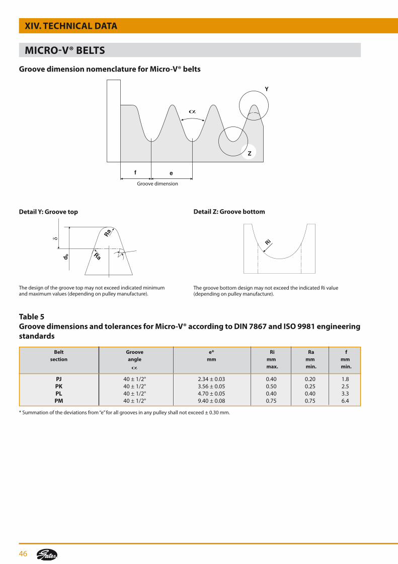
46
Y
Z
ef
ThegroovebottomdesignmaynotexceedtheindicatedRivalue(depending on pulley manufacture).
Groove dimension
detail Z: Groove bottomdetail y: Groove top
Thedesignofthegroovetopmaynotexceedindicatedminimumandmaximumvalues(dependingonpulleymanufacture).
table 5Groove dimensions and tolerances for Micro-V® according to dIn 7867 and ISo 9981 engineering standards
*Summationofthedeviationsfrom“e”forallgroovesinanypulleyshallnotexceed±0.30mm.
Groove dimension nomenclature for Micro-V® belts
XIV. tEchnIcAL dAtA
MIcro-V® BELtS
Belt Groove e* ri ra f section angle mm mm mm mm max. min. min.
PJ 40±1/2° 2.34±0.03 0.40 0.20 1.8 Pk 40±1/2° 3.56±0.05 0.50 0.25 2.5 PL 40±1/2° 4.70±0.05 0.40 0.40 3.3 PM 40±1/2° 9.40±0.08 0.75 0.75 6.4
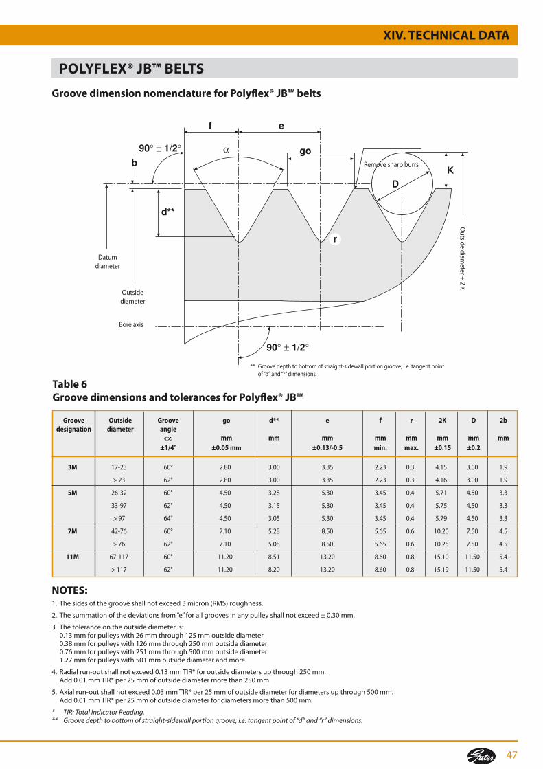
47
r
go
e
b
d**
90 1/2
90 1/2
DK
f
table 6Groove dimensions and tolerances for Polyflex® JB™
notES:1. Thesidesofthegrooveshallnotexceed3micron(RMS)roughness.
2. Thesummationofthedeviationsfrom“e”forallgroovesinanypulleyshallnotexceed±0.30mm.
3. The tolerance on the outside diameter is: 0.13mmforpulleyswith26mmthrough125mmoutsidediameter 0.38mmforpulleyswith126mmthrough250mmoutsidediameter 0.76mmforpulleyswith251mmthrough500mmoutsidediameter 1.27mmforpulleyswith501mmoutsidediameterandmore.
4. Radialrun-outshallnotexceed0.13mmTIR*foroutsidediametersupthrough250mm. Add0.01mmTIR*per25mmofoutsidediametermorethan250mm.
5.Axialrun-outshallnotexceed0.03mmTIR*per25mmofoutsidediameterfordiametersupthrough500mm. Add0.01mmTIR*per25mmofoutsidediameterfordiametersmorethan500mm.
* TIR: Total Indicator Reading.** Groove depth to bottom of straight-sidewall portion groove; i.e. tangent point of “d” and “r” dimensions.
Groove dimension nomenclature for Polyflex® JB™ belts
PoLyfLEX® JB™ BELtS
XIV. tEchnIcAL dAtA
** Groovedepthtobottomofstraight-sidewallportiongroove;i.e.tangentpoint of “d” and “r” dimensions.
Outsidediameter
Boreaxis
Remove sharp burrs
Datum diameter
Outsidediam
eter+2K
Groove outside Groove go d** e f r 2k d 2b designation diameter angle mm mm mm mm mm mm mm mm ±1/4° ±0.05 mm ±0.13/-0.5 min. max. ±0.15 ±0.2
3M 17-23 60° 2.80 3.00 3.35 2.23 0.3 4.15 3.00 1.9
>23 62° 2.80 3.00 3.35 2.23 0.3 4.16 3.00 1.9
5M 26-32 60° 4.50 3.28 5.30 3.45 0.4 5.71 4.50 3.3
33-97 62° 4.50 3.15 5.30 3.45 0.4 5.75 4.50 3.3
>97 64° 4.50 3.05 5.30 3.45 0.4 5.79 4.50 3.3
7M 42-76 60° 7.10 5.28 8.50 5.65 0.6 10.20 7.50 4.5
>76 62° 7.10 5.08 8.50 5.65 0.6 10.25 7.50 4.5
11M 67-117 60° 11.20 8.51 13.20 8.60 0.8 15.10 11.50 5.4
>117 62° 11.20 8.20 13.20 8.60 0.8 15.19 11.50 5.4
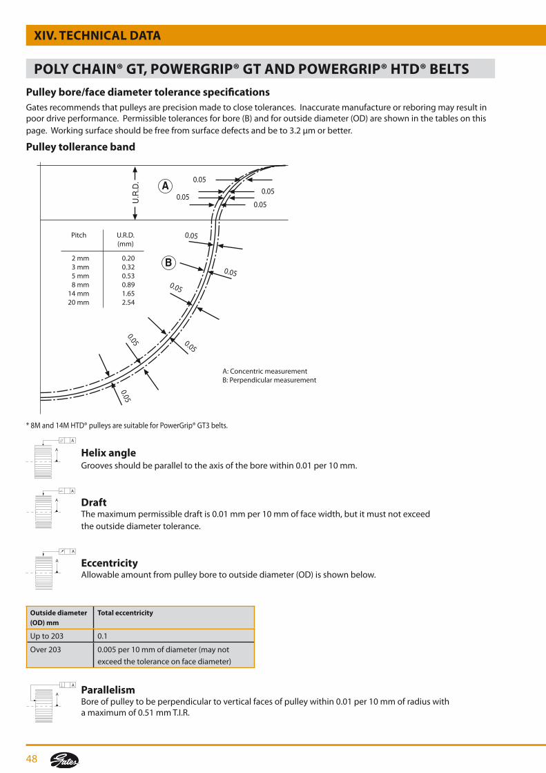
48
XIV. tEchnIcAL dAtA
Pulley bore/face diameter tolerance specificationsGates recommends that pulleys are precision made to close tolerances. Inaccurate manufacture or reboring may result in poor drive performance. Permissible tolerances for bore (B) and for outside diameter (OD) are shown in the tables on this page.Workingsurfaceshouldbefreefromsurfacedefectsandbeto3.2µmorbetter.
Pulley tollerance band
Pitch U.R.D. (mm)
2mm 0.20 3mm 0.32 5mm 0.53 8mm 0.89 14mm 1.65 20mm 2.54
A:ConcentricmeasurementB: Perpendicular measurement
A
B
U.R
.D. 0.05
0.05
0.050.05
0.05
0.05
0.050.05 0.05
0.05
*8Mand14MHTD®pulleysaresuitableforPowerGrip®GT3belts.
helix angle Groovesshouldbeparalleltotheaxisoftheborewithin0.01per10mm.
draft Themaximumpermissibledraftis0.01mmper10mmoffacewidth,butitmustnotexceed the outside diameter tolerance.
Eccentricity Allowable amount from pulley bore to outside diameter (OD) is shown below.
outside diameter (od) mm
total eccentricity
Upto203 0.1
Over203 0.005per10mmofdiameter(maynot
exceedthetoleranceonfacediameter)
Parallelism Boreofpulleytobeperpendiculartoverticalfacesofpulleywithin0.01per10mmofradiuswith amaximumof0.51mmT.I.R.
A
A
A
A
A
A
A
A
PoLy chAIn® Gt, PoWErGrIP® Gt And PoWErGrIP® htd® BELtS
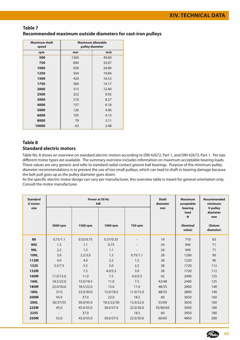
49
table 7recommended maximum outside diameters for cast-iron pulleys
table 8Standard electric motorsTableNo.8showsanoverviewonstandardelectricmotorsaccordingtoDIN42672,Part1,andDIN42673,Part1.Persizedifferentmotortypesareavailable.Thesummaryoverviewincludesinformationonmaximumacceptablebearingloads.These values are very generic and refer to standard radial contact groove ball bearings. Purpose of the minimum pulley diameter recommendations is to prevent the use of too small pulleys, which can lead to shaft or bearing damage because the belt pull goes up as the pulley diameter goes down.As the specific electric motor design can vary per manufacturer, this overview table is meant for general orientation only. Consultthemotormanufacturer.
Standard Power at 50 hz Shaft Maximum recommended E-motor kW diameter acceptable minimum size mm bearing V-pulley load diameter n mm
3000 rpm 1500 rpm 1000 rpm 750 rpm (nominal (datum value) diameter)
80 0.75/1.1 0.55/0.75 0.37/0.55 - 19 710 63
90S 1.5 1.1 0.75 - 24 940 71
90L 2.2 1.5 1.1 - 24 940 71
100L 3.0 2.2/3.0 1.5 0.75/1.1 28 1200 90
112M 4.0 4.0 2.2 1.5 28 1220 90
132S 5.5/7.5 5.5 3.0 2.2 38 1720 112
132M - 7.5 4.0/5.5 3.0 38 1720 112
160M 11.0/15.0 11.0 7.5 4.0/5.5 42 2400 125
160L 18.5/22.0 15.0/18.5 11.0 7.5 42/48 2400 125
180M 22.0/30.0 18.5/22.0 15.0 11.0 48/55 2800 140
180L 37.0 22.0/30.0 15.0/18.5 11.0/15.0 48/55 2800 140
200M 45.0 37.0 22.0 18.5 60 3650 160
200L 30/37/55 30.0/45.0 18.5/22/30 15.0/22.0 55/60 3650 160
225M 45.0 45.0/55.0 30.0/37.0 22.0/30.0 55/60/65 3950 180
225S - 37.0 - 18.5 60 3950 180
250M 55.0 45.0/55.0 30.0/37.0 22.0/30.0 60/65 4850 200
Maximum shaft Maximum allowable speed pulley diameter
rpm mm inch
500 1260 49.60
750 840 33.07
1000 630 24.80
1250 504 19.84
1500 420 16.53
1750 360 14.17
2000 315 12.40
2500 252 9.92
3000 210 8.27
4000 157 6.18
5000 126 4.96
6000 105 4.13
8000 79 3.11
10000 63 2.48
XIV. tEchnIcAL dAtA

50
table 9Minimum recommended idler diameters
XIV. tEchnIcAL dAtA
Belt section
Min o.d. of grooved inside idler Min o.d. of flat outside idler
mm inch mm inch
Predator®single belt
SPBP 160 6.30 250 9.84
SPCP 250 9.84 400 15.75
AP 85 3.35 110 4.33
BP 112 4.41 160 6.30
CP 160 6.30 220 8.66
8VP 317 12.48 445 17.52
Quad-Power® II
XPZ / 3VX 56 2.20 85 3.35
XPA 80 3.15 120 4.72
XPB / 5VX 112 4.41 168 6.61
XPC 180 7.09 270 10.63
Super hc® Mn
SPZ 56 2.20 85 3.35
SPA 80 3.15 120 4.72
SPB 112 4.41 168 6.61
SPC 180 7.09 270 10.63
Super hc®
SPZ / 3V / 9J 71 2.80 120 4.72
SPA 100 3.94 160 6.30
SPB / 5V / 15 J 160 6.30 250 9.84
SPC 250 9.84 350 13.78
8V / 25J 315 12.40 450 17.72
8VK 425 16.73 500 19.69
hi-Power®
Z 60 2.36 90 3.54
A 85 3.35 110 4.33
B 112 4.41 160 6.30
C 160 6.30 220 8.66
D 300 11.81 350 13.78
E 500 19.69 600 23.62
hi-Power®dubl-V
AA 85 3.35 * *
BB 112 4.41 * *
CC 160 6.30 * *
DD 330 12.99 * *
VulcoPower™
Z 60 2.36 90 3.54
A 85 3.35 110 4.33
B 112 4.41 160 6.30
C 160 6.30 220 8.66
VulcoPlus™
SPZ 71 2.80 120 4.72
SPA 100 3.94 160 6.30
SPB 160 6.30 250 9.84
SPC 250 9.84 400 15.75

51
Belt section
Min o.d. of grooved inside idler Min o.d. of flat outside idler
mm inch mm inch
Predator®PowerBand®
SPBP 160 6.30 250 9.84
SPCP 250 9.84 400 15.75
9JP 71 2.80 110 4.33
15JP 160 6.30 250 9.84
8VP 317 12.48 445 17.52
Quad-Power® IIPowerBand®
3VX 71 2.80 100 3.94
5VX 112 4.41 180 7.09
XPZ 56 2.20 80 3.15
XPA 96 3.78 144 5.67
XPB 135 5.31 192 7.56
Super hc® PowerBand®
SPB 160 6.30 250 9.84
SPC 250 9.84 400 15.75
9J / 3V 71 2.80 108 4.25
15J / 5V 160 6.30 250 9.84
25J / 8V 317 12.48 445 17.52
hi-Power®PowerBand®
B 137 5.39 180 7.09
C 228 8.98 300 11.81
D 330 12.99 430 16.93
Powerated®
3L 38 1.50 50 1.97
4L 64 2.52 83 3.27
5L 89 3.50 116 4.57
Polyflex® JB™
3M-JB 17 0.67 * *
5M-JB 26 1.02 * *
7M-JB 42 1.65 * *
11M-JB 67 2.64 * *
Polyflex®
3M 17 0.67 * *
5M 26 1.02 * *
7M 42 1.65 * *
11M 67 2.64 * *
Micro-V®
PJ 20 0.79 32 1.26
PL 75 2.95 115 4.53
PM 180 7.09 270 10.63
table 9 (continued)Minimum recommended idler diameters
XIV. tEchnIcAL dAtA
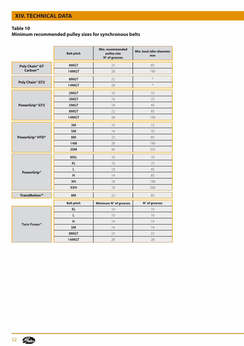
52
table 10Minimum recommended pulley sizes for synchronous belts
XIV. tEchnIcAL dAtA
Belt pitchMin. recommended
pulley size n° of grooves
Min. back idler diameter mm
Poly chain® Gt carbon™
8MGT 22 85
14MGT 28 190
Poly chain® Gt28MGT 22 *
14MGT 28 *
PowerGrip® Gt3
2MGT 10 10
3MGT 16 25
5MGT 18 45
8MGT 22 85
14MGT 28 190
PowerGrip® htd®
3M 10 15
5M 14 35
8M 22 85
14M 28 190
20M 34 325
PowerGrip®
MXL 10 10
XL 10 25
L 10 45
H 14 85
XH 18 190
XXH 18 260
transMotion™ 8M 22 85
Belt pitch Minimum n° of grooves n° of grooves
Twin Power®
XL 10 10
L 10 10
H 14 14
5M 14 14
8MGT 22 22
14MGT 28 28

53
XIV. tEchnIcAL dAtA
Belt pitchMin. recommended
pulley size n° of grooves
Min. back idler diameter mm
Synchro-Power®
T2.5 12 20
T5 10 30
T10 14 80
AT5 15 60
AT10 15 120
T5DL 12 20
T10DL 18 57
Synchro-Power® LL
T5 10 30
T10 14 80
T10HF 12 60
T20 15 120
AT5 15 60
AT10 15 120
ATL10 25 150
ATL10HF 20 130
AT20 18 180
ATL20 30 250
HTD5M 14 60
HTD8M 20 120
HTD14M 28 180
HTDL14M 43 250
HPL14M 44 250
STD5M 14 60
STD8M 20 120
XL 10 30
L 10 60
H 14 80
XH 12 150
table 10 (continued)Minimum recommended pulley sizes for synchronous belts

54
10 10 15 20 15 25 25 20 25 35 20 30 40 40 30 40 45 35 45 60 45 65 50 70 55 85 65 100 70 115
25 35 40 45 55 65 85 95 110
PJ PL PM
- 500 501 - 1000 1001 - 1500 1501 - 2000 2001 - 2500 2501 - 3000 3001 - 4000 4001 - 5000 5001 - 6000 6001 - 7500 7501 - 9000 9001 -
3M-JB 7M-JB 11M-JB
180 - 272 280 - 300 307 - 710 730 - 1090 1120 - 1500 1550 - 1900 1950 - 2300
XPZ XPA XPB SPc 8V 9J 15J 8V Z A A B B c c d 3VX SPA 5VX 8Vk PB PB PB PB PB PB SPZ SPB 25J SPB SPc 3V 5V PB PB PB
15 20 - - - 30 - - 15 20 30 25 35 40 50 - 20 25 25 - - 35 55 - 20 20 30 30 40 40 50 50 20 25 25 35 40 35 55 85 20 25 35 30 40 40 50 50 20 25 25 35 40 35 55 85 - 25 35 30 40 40 50 50 20 25 25 35 40 35 55 85 - 25 35 30 40 50 60 55 - 25 25 35 45 - 55 90 - 25 35 40 50 50 60 60 - - 35 40 45 - 60 90 - 25 35 40 50 50 60 60 - - 35 40 45 - 60 90 - - - 40 50 50 60 65 - - 35 45 50 - 60 100 - - - - 50 50 60 65
420 - 1199 1200 - 1999 2000 - 2749 2750 - 3499 3500 - 4499 4500 - 5499 5500 - 6499 6500 - 7999 8000 -
PB=PowerBand®
5M-JB
table 11Minimum installation and takeup allowance
All sections
datum lengthmm
V-belt section
Minimumtakeup
allowancemm
Minimum installation allowance - mm
Micro-V® belt section
Minimum installation allowance - mmEffective lengthmm
Minimum takeup allowancemm
All sections
Polyflex® JB™ belt section
Minimum installation allowance - mmEffective lengthmm
Minimum takeup allowancemm
All sections
MIcro-V® BELtS
PoLyfLEX® JB™ BELtS
V-BELtS
XIV. tEchnIcAL dAtA
5 - - - - 7.5 10 - - 5 10 15 15 25 15 - 25 25 30 30 - 30 30 35 35 - - 30 40 35 - - 40 50 45
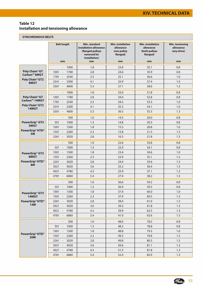
55
PowerGrip® Gt35MGt
PowerGrip® htd®5M
PowerGrip® Gt38MGt
PowerGrip® htd®8M
PowerGrip® Gt314MGt
PowerGrip® htd®14M
Poly chain® Gt carbon™ 8MGt
Poly chain® Gt2 8MGt
Poly chain® Gt carbon™ 14MGt
Poly chain® Gt2 14MGt
PowerGrip® htd®20M
Belt length Min. standard Min. installation Min. installation Min. tensioning installation allowance allowance allowance allowance (flanged pulleys (one pulley (both pulleys (any drive) removed for flanged) flanged) installation) mm mm mm mm mm
- 1000 1.8 23.8 35.1 0.8 1001 - 1780 2.8 24.6 35.9 0.8 1781 - 2540 3.3 25.1 36.6 1.0 2541 - 3300 4.1 25.9 37.4 1.0 3301 - 4600 5.3 27.1 38.6 1.3
- 1000 1.8 33.0 51.8 0.8 1001 - 1780 2.8 34.0 52.8 0.8 1781 - 2540 3.3 34.5 53.3 1.0 2541 - 3300 4.1 35.3 54.1 1.0 3301 - 4600 5.3 36.5 55.3 1.3
- 500 1.0 14.5 20.0 0.8 501 - 1000 1.3 14.8 20.3 0.8 1001 - 1500 1.8 15.3 20.8 1.0 1501 - 2260 2.3 15.8 21.3 1.3 2261 - 3020 2.8 16.3 21.8 1.3
- 500 1.0 22.6 33.8 0.8 501 - 1000 1.3 22.9 34.1 0.8 1001 - 1500 1.8 23.4 34.6 1.0 1501 - 2260 2.3 23.9 35.1 1.3 2261 - 3020 2.8 24.4 35.6 1.3 3021 - 4020 3.6 25.2 36.4 1.3 4021 - 4780 4.3 25.9 37.1 1.3 4781 - 6860 5.4 27.0 38.2 1.3
- 500 1.0 36.6 59.2 0.8 501 - 1000 1.3 36.9 59.5 0.8 1001 - 1500 1.8 37.4 60.0 1.0 1501 - 2260 2.3 37.9 60.5 1.3 2261 - 3020 2.8 38.4 61.0 1.3 3021 - 4020 3.6 39.2 61.8 1.3 4021 - 4780 4.3 39.9 62.5 1.3 4781 - 6860 5.4 41.0 63.6 1.3
- 500 1.0 48.0 78.5 0.8 501 - 1000 1.3 48.3 78.8 0.8 1001 - 1500 1.8 48.8 79.3 1.0 1501 - 2260 2.3 49.3 79.8 1.3 2261 - 3020 2.8 49.8 80.3 1.3 3021 - 4020 3.6 50.6 81.1 1.3 4021 - 4780 4.3 51.3 81.8 1.3
4781 - 6860 5.4 52.4 82.9 1.3
table 12Installation and tensioning allowance
SynchronouS BELtS
XIV. tEchnIcAL dAtA

56
PowerGrip® L
PowerGrip® XL
PowerGrip® h
PowerGrip® Xh
PowerGrip® XXh
Belt length Min. standard Min. installation Min. installation Min. tensioning installation allowance allowance allowance allowance (flanged pulleys (one pulley (both pulleys (any drive) removed for flanged) flanged) installation) mm mm mm mm mm
90 - 127 0.50 12.20 18.50 0.50 128 - 254 0.75 12.50 18.75 0.75 255 - 508 1.00 12.70 19.00 0.75 509 - 1016 1.30 13.00 19.30 1.00 1017 - 1524 1.80 13.50 19.80 1.30 1525 - 4572 3.10 14.80 21.10 2.10
90 - 127 0.50 16.80 22.10 0.50 128 - 254 0.75 17.00 22.40 0.75 255 - 508 1.00 17.30 22.60 0.75 509 - 1016 1.30 17.60 22.90 1.00 1017 - 1524 1.80 18.10 23.40 1.30 1525 - 4572 3.10 19.40 24.70 2.10
90 - 127 0.50 16.80 24.90 0.50 128 - 254 0.75 17.00 25.20 0.75 255 - 508 1.00 17.30 25.40 0.75 509 - 1016 1.30 17.60 25.70 1.00 1017 - 1524 1.80 18.10 26.20 1.30 1525 - 4572 3.10 19.40 27.50 2.10 90 - 127 0.50 29.50 49.30 0.50 128 - 254 0.75 29.80 49.60 0.75 255 - 508 1.00 30.00 49.80 0.75 509 - 1016 1.30 30.30 50.10 1.00 1017 - 1524 1.80 30.80 50.60 1.30 1525 - 4572 3.10 32.10 51.90 2.10
90 - 127 0.50 39.40 67.80 0.50 128 - 254 0.75 39.70 68.10 0.75 255 - 508 1.00 39.90 68.30 0.75 509 - 1016 1.30 40.20 68.60 1.00 1017 - 1524 1.80 40.70 69.10 1.30 1525 - 4572 3.10 42.00 70.40 2.10
table 12 (continued)Installation and tensioning allowance
XIV. tEchnIcAL dAtA

57
Weights and measures
table 13Estimating belt length from drive components(2 pulleys)
Belt length=2C+1.57(D+d)+
Where: C=shaftcentredistance
a) ForPoweRated®,Polyflex®,Micro-V®andallRMAPowerBand®belts:
belt length = belt effective length D = O.D. of larger pulley d = O.D. of smaller pulley
b)ForPredator®,SuperHC®MN,SuperHC®,Hi-Power®,VulcoPower™,VulcoPlus™andallmetricPowerBand®belts:
belt length = datum length D = datum diameter of larger pulley d = datum diameter of smaller pulley
c) Forsynchronousbelts:
belt length = pitch length D = pitchdiameteroflargerpulley=N°teethxpitch/π d = pitchdiameterofsmallerpulley=N°teethxpitch/π
1lbf = 0.454kgf
1lbf = 4.448N
1kgf = 9.807N
1lbfin = 0.113Nm
1ft = 0.3048m
1in = 25.4mm
1 ft2 = 0.093m2
1 in2 = 645.16mm2
1 ft3 = 0.028m3
1 in3 = 16.387cm3
1oz = 28.35g
1lb = 0.454kg
1UKton = 1.016ton
1UKgal = 4.546litres
1UKpint = 0.568litre
1radian = 57.296degrees
1degree = 0.0175radian
1HP = 0.746kW
XIV. tEchnIcAL dAtA
(D - d)2
4C

58
XV. SuPPort
Save energy and costs with Gates cost saving programme!Are high maintenance costs and premature belt failures an issue atyourplant?Areyousureyourdrivesystemworksinthemosteconomicway? TheGates cost savingprogrammecontains all the tools and support necessary to redesign yourproblemdriveandtocalculatehowtomakeyourtransmissionevenmoreefficient.
Gates Area Account Managers are available to conduct performance evaluations on your plant and develop a maintenance recommendation plan for energy cost savings, that will optimise all belt drives in your facility.
this is how it works:• WeevaluatecurrentbeltdriveefficienciesusingGates DesignFlex®andCostSavingCalculationTool.• Wecalculateenergysavingsgainedbyreplacingproblemdrivesor chaindriveswithenergy-efficientones.• Weidentifyproblemdriveapplicationsanddevelopaprogrammeto increase their reliability.• Werecommendlonger-lastingproductsthatwillenhanceproductivity andimproveequipmentreliability.• Wedeterminewaystoreducemaintenancecosts (retensioning, lubrication, …).• Wedevelopapreventativemaintenanceprogrammetomaximisethe life of all belt drives in your facility.
Energy saving exampleHeat, ventilation and air conditioning
• Motor:40kW,11,450rpm,89%efficient
Hoursused:24hours/day,7days/week,52weeks/yearEnergycost:0.06645EUR/kWh
• Costofanewsynchronousbeltdrive:765.6EUR
• Assumea5%increaseinefficiencyoveraV-beltdrive
Annual energy cost: 40kWx8,736hoursx0.06645EUR=23,220.30EURAnnual energy savings: 23,220.30EURx0.05=1,161EUR
• Paybackperiod: 765.60EUR/1,161EUR=0.66yearsor7months
Behind our leading industrial products is an entire company of professionals, armed with solutions. Whether driven by people, equipment or technology, Gates provides a wide range of services to optimise belt drive performance and deliver the best value to customers in return for their investment in Gates’ products.

59
Gates drive design softwareGates puts forward two fast and easy resources for selecting and maintaining belt drive systems. DesignFlex®Pro™andDesignIQ™,onlinedrivedesignandengineering tools, assistdesigners inquickly selectingoptimum drive solutions. With the Gates multilingual DesignFlex®Pro™programme,youcandesignadriveinminutes, and get every possible drive solution that fits your design parameters. Plus, you can print, e-mail and createaPDFof thedesign specifications. Design IQ™providesablankslatefordesigningmultipointandcomplexserpentinebeltdrives.UtilisingaspecificGatesproductthatyou have identified, as well as your drive specifications, the software will calculate belt tension, shaft load, belt length and more.
Gates e-commerce websiteBy going online registered Gates distributors can find the most current product information,enterorders24hours/dayandtrackordersatanytime.GateselectronicpricelistsbothinEXCELandPDFformatscanbeconsultedfromthee-commercewebsite www.gates-online.com. To request freeprintedcopiesof theprice listavailable in several languages, just contact your Gates representative.
Gates literature and websitePlease consult our website at www.gates.com/europe/pti for specific and updated information on all Gates industrial belt products and our list of available literature. Industrial Power Transmission brochures and leaflets can be downloaded there. DistributorsmaylinkupwiththeGatesEuropeansitethussupplyingvisitorswithupdatedinformationontheEuropeanGatesorganisation.
rEAch: Environment-friendly and safe quality productsREACH isanewEuropeanCommunity regulationonchemicalsandtheir safeuse. It stands forRegistration,Evaluation,AuthorisationandRestrictionofChemicalsubstances(2006/1907/EC).TheaimofREACHistoimprovetheprotectionofhumanhealth and the environment through the better and earlier identification of the intrinsic properties of chemical substances.Fromitsrespectfortheenvironmenttoindustrialsafety,GatestakesitsresponsibilityintheproductionofindustrialbeltsveryseriouslyandadheresscrupulouslytotherequirementslaiddownintheREACHregulation.AllsubstancesinourbeltproductsrequiringregistrationhavebeenregisteredinthecentraldatabaserunbytheEuropeanChemicalsAgency(ECHA).ThisdatabasecanbeconsultedinordertocheckproductsonREACHconformity.All standard V-belts and synchronous belts, listed in the Gates Industrial Power Transmission Catalogue (E2/20054), are REACH compliant, except for PoweRated®, Super HC® PowerBand® SPC and the 5 smallest Micro-V® belts with DIN/ISO effective length ranging from 406 mm up to 508 mm (PJ406, PJ432, PJ457, PJ483 and PJ508).
Gates manufacturing and distribution in EuropeGatesPowerTransmissionIndustrialhasproductdedicatedproductionsitesinGermany,Poland,Scotland,FranceandSpain.Distribution is handled from one central warehouse in Ghent (Belgium).
XV. SuPPort

60

61
request for an expertise of your machine park
If youwant to saveenergyandcosts? HaveyourplantcheckedbyaGates representativeorGatesdistributor.
FilloutthisformandgiveittoaGatesrepresentative.YoucanalsofaxittoMartineMeert(+3253762713)ore-mailit([email protected])andwewillcontact you.
Your company:……………………………………………………………………………………
Your industry
Chemistryandpetrochemistry
Food,pharmaceutical
Automobile
Wood, paper
Consumergoods(nonfood)
Aggregates
Textile
Environment
Name: ………………………………………………………………………………………
Your position within the company: ………………………………………………………………………………………
Address: ……………………………………………………………………………………… ………………………………………………………………………………………
Telephone: ………………………………………………………………………………………
Fax: ………………………………………………………………………………………
E-mail: ………………………………………………………………………………………
XV. SuPPort

62

63
NOTES

64
NOTES

65
All Gates’ European Power Transmission operations are ISO 9001, ISO 14001 and OHSAS 18001 registered.
The manufacturers reserve the right to amend details where necessary. © Gates Corporation 2009 Printed in Belgium - 05/09.
Important
Every effort has been made to ensure the accuracy and comprehensiveness of the information included in this manual. However, Gates cannot be held responsible for errors or omissions and for alterations occurred after release for printing; or if Gates products are used in special or exceptional circumstances without prior consultation with and clearance from a Gates representative.
This issue is released May 2009 and supersedes all previous versions of this preventive maintenance manual. If your preventive maintenance manual is more than 2 years old, please consult a Gates representative to check whether you have the latest version.

BELGIUMGates Power Transmission Europe bvbaDr. Carlierlaan 309320 ErembodegemTL: (32) 53 76 28 41FX: (32) 53 76 26 09
FRANCEGates France S.A.R.L.B.P. 372, Rue de la BriqueterieZone Industrielle95380 LouvresTL: (33) 1 34 47 41 45FX: (33) 1 34 72 20 54
GERMANYGates GmbH AachenEisenbahnweg 5052068 AachenTL: (49) 241 5108 226FX: (49) 241 5108 297
ITALYGates S.R.L.Via Senigallia 18(Int. 2 - Blocco A - Edificio 1)20161 Milano MITL: (39) 02 662 16 222FX: (39) 02 662 21 851
RUSSIAGates CIS LLC1-st Dobryninsky per.building 15/7Moscow - 115 093TL: (7) 495 933 83 78FX: (7) 495 648 92 72
www.gates.com/europe/[email protected]
Your distributor:
The manufacturers reserve the right to amend details where necessary. © Gates Corporation 2009 Printed in Belgium - 05/09.


