. .’ .> FOR AERONAUTICS 1 u N(IV IY4/ TECHNICAL NOTE No. 1482 .- .-. , A METHOD OF CALCULATING THE COMPRESSIVE STRENGTK OF Z-STIFFENED PANELS THAT DEVELOP LOCAL INSTABILITY By George L. Gallaher and Rolls B< Boughan — Lamgley Memorial Aeronautical Laboratory Langley Field, Va. Washington November 1947 /’ — https://ntrs.nasa.gov/search.jsp?R=19930082136 2018-07-12T22:44:02+00:00Z
Transcript
.
.’.>
FOR AERONAUTICS1 u N(IV IY4/
TECHNICAL NOTE
No. 1482 .-.-. ,
A METHOD OF CALCULATING THE COMPRESSIVE
STRENGTK OF Z-STIFFENED PANELS
THAT DEVELOP LOCAL INSTABILITY
By George L. Gallaher and Rolls B< Boughan
—
Lamgley Memorial Aeronautical LaboratoryLangley Field, Va.
A method2 based on the elastic theory for plate ‘buckli~ andtest results for 24s-T aluminum-alloy Z-stiffened panels: is shown ,for calculating the compressive strength of”%stii?fened”panels thqtidevelop local.instability. This method cem be used to oalculatethe critical compressive stress above, as well’as w~thin, the .,“elastic range, For stressee above three-fourths the compressiveyield.stress the method can be used for the.approximate determina-tion of the average compressive stress at meximum load.
..
3XTRODUOTION
For maximum aerodynamic efficiency of ati~ the compression .panels in the wing should not buckle even when the applied loadreaches high values. This requirement @es it necessary foraircraft designers to know the critical compressive stress - thestress at which buckling of the plate elements occurs - for thestiffened panels that make up the wing surfaces. & addition,the designer should have information available on the averagecompressive stress at maximum load, because the”design of stressebskin structures is based upon the strength of the section,. .
As sn approach to solving these problems for =stiffened panels,a method.of calculating the elastic theoretical.buokling stress forlocal instability of &stiffened panels is-presented. This’methodis extended to the calculation of,the critical comp~essive stress,above the elastic range on the basis of test results for 24=
. sluminm+alloy %-stiffened panels. T4e same method maybe used.to calculate a reasonable value of average stress at maximum loadfor Er&esses above three-fourths the yie~d stress.
.
/
2 .. . . . .. -!”..-:- -------- --.-~-
$NACA.TNRO, 14&,,...’ .. ........’..
,Sm3Q “.
‘b wiflthof,plate element of panel ‘, .
‘t thickness of plate eleme~t .ofpanel
E Youngts modulus of elasticity (taken.ao 10.”7X 10⁶ put)
Eeeo secant modulu,a’(ratio ot ordinate to abcissiaof dmms-sttiin curve)
fi *MS formula t and b ‘are the thtckness and the width,respectively, of the plate under oonsideration~ E is Young*s~dtius; v is Poisson?sratio; and k’ ig a,oopfftcient”thatis detemnined ti,omthe relativa proportions of thecross section.The sam equation maybe adapted to plato assczublios. As applied
where the subsoript S “refers to the skin or thestiffeners.
,.
With equatfoti(2) tk elastic valw ,ofacr...
-...”
,..(2)
platebetween the
,,
mm %e a’tic~ated
for titffened p&eh3 oqe the vaJue of ~ ts’known. In-order
to evaluate ~ for Z2.stiffenedpazielskhe aot~ pe&l orpss
section shown in figure l(a) was idealf.w% to that eh~ infigure l(b), we values of ks for this Mealizecl panel are
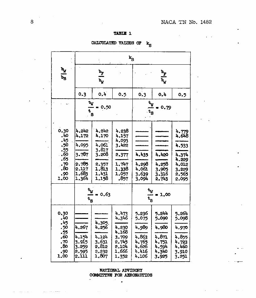
given by the cvrves of fi~ 2.” These curves are similar tothose for the web- and Wsttffenal psnelb or reference 1 and wereprepared in the S- manner. Table 1 gives the comptied valussof ~ used for constructing these charts.
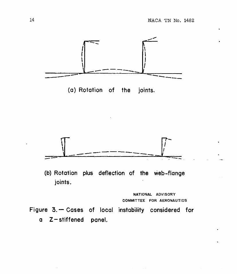
The basic assumption for ca@uIat ing k~ 5s that,,upon ‘
buOldAng, otiy ,rotationof the joints oocurs (as.in fig. 3(a)).‘“It is recognized tl+at,as %he various cMuensLor@ rat$os vwfrom one extreme to thq other, this assumption is’not cqnpletel$true. As-the ratio ~1.~ decreases to 0.3 and 3ss8, the
ability of the stiffener”to resi~t lat~ral deflection.of theweb+flan~ joint (buc~tng as in fig. S(b)) deGrQases. Thisdeflection,‘whichresults in rotation ‘ofthe .d~f fener, becomesmore prorymnoed f or wjde stifferiers~cfng {smell rati,os.of l#bS)
becaqse’j.nsuoh cases the skin Is primarily respc%sihle for theinstability a@ therefore establishes a“’buclde pattern with a .longer wave length th&a the wave length which z~sults when som.pati of the stiffener.is primarily responsible for the instability,Because the lateral deflection must be resiste~ in iarge measure ..bythe bending sttffness “oft% f@nge -asa beam of depth ~, t~a ...
krger ~he wa~e”length the less the resistbnoe “tothis ‘&f16ct30n.It is believed, however, that the .val.uesof ~%).,- %/%tnfi’
r8. 2 a%3 Hufficiektly large to pr&ent ~hfs rlateral def’lg&-
tion or stl$’fqnerrotation) “frombecoming mat enou@ to reduoo .‘noticeably the values of R.
.’ RESULTS AND lllSOWSSZON”.’
,, .
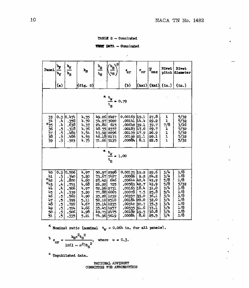
Available test data on 24.S-Jl!alumintiloy Z-stiffened panels‘ havi~fornmd stiffenem (~ee ta~le 2) are presented to verify thecalculated elastic theoretical stress’givenby equa~fon (2).These test data include data obtained from references 2 and 3,along with s- qdditionaldata.not previously published. Allof these experimental values of crcl, were established by the
strain-reversalmethod descrfbed ‘inreference 4 and are for panelsthat are considered strongly riveted. The rfvet pitch and diameterof thesetest.panels is included in table 2. The.pfPect of rivetpitch and diameter on the strength of panels is discussed Inreference ~.
As in the case of reference 6,”t~ test [email protected] are plottedagainst the calculated elastic Crltl.calcompressive strain Gcr
for.purposes oi’eomparlson”wtth“acompressive stress-strain curve.The e,quationfor Ccr is obtained by d~viding both sides of
equation’(2) by E, @vlng.,.
.,,. ‘ kS$~2” “- ‘“
‘ 6cr “ ——
“ 12(1 - v2)bS2
*.(3)
Figure 4 shows the data plotted in this manner: The compressiveqtress-strain curves shown,representthe ~imm.u and minimun .compressive properties for the 24SJT @..yuuiuuu+Q.loyshee~ use-din forming the test panels which buckled above t~ elastfc,[email protected] average yield stress’forthe materialwa= 43.0 ksi.
. . ,, .
The buckling data follow the st~ss-strain curves quite”closely over the entire range. This fact indicates tliepoeslbilityof.using the secant [email protected] Eeec instead of Youngts modulus E’,.in equation(2), as was sugge’sted;inreference 6“f,or i, %,and C-section plate assemblies. The,use O? the sec~nt”mgdulus for.%he bucklfng of plates has dso.bcenpropa~dhy~rmd inreferehoe 7. The test data indicate that the use of, Esec in -.. -.equation (2} will.give values that are slifjxtlyWconseryativeabove the elastic rsnge. ‘14henthe averk~ str6i8-strain c~e wasused, the amount of UnconservakTsmwaa faund to vary from 0.2 percen$
.
to 10,5 percent,and to average @out 6 percen>,~@. ~,t!em$.!O_~ducethe scatter by,referri~.e~oh tos’tpoint to its individual.stress- .
strain curve showed only a little impfiuvement.This result was
.. .
NACA TN No. lk82 5.
.
.
.
probably due largely to the difficulty in obtaining a ~ood repre-sentati% stress+ train curve for each specimen because of thevariation in properties caused by fomning and by the use ofdifferent sheet material in the skin and stiffeners.
When buckling occurred,at high stresses, values of the averageh“~ss at maximum load Vmx were found to be only slightly geater -
than acr. These Fm valusehave been included in ftgurq 4 to
show the close agreement between” dcr !&d 5 .athigh stresses,
This result is simtlar to that for the E-, Z-, and C-sections inreference 6 for stresses greater thm three-fourths the compressiveyield stress cc~* UiiLilmthe yegtits obtalnod for these.qections,
the value of 3= for the panels with ”kresses less than about
3Kacy
did not fall in a single curve and are not shown in figure ~~
because of the considerable scatter. Because values of ~mx
follow the stress-strain curves very closely for stresses above
;Cfcy,the plate IIuckkhg equation with Efiec substituted for E
can also be used to calculate approximate values of ~mx in this
region, (This method has been suggested previously for H-, Z-, andC-section plate asseribliesin reference 6.)
CONCLUSIONS
.
The following conclusions are based upon thetest results for 24E+T aluluin~loy Z-stiffenedformed stiffeners strongly riveted *O the skin:
1. The critical compressive stress for local
local instabilitypanels having
instability maybe calculated from the plate buckling equation with the secsntmodulus substituted for Young~s modit.us. This fommla is
kS#E=eJ#cCr =
12(1 -v2)bS2
where kS is the buckling stress coefficient; t~ snd bS are
the thiclmess end width of the skin plate, respectively; v is
6 NACA ~ NO. 14%2
PoissonSb ratio; tid E~ec is the secant modulus. The results
obtained by the use of this fozmwla are reasonably accurate withinthe elastic range but tqnd to be on the.average about 6 percentunconsorvative above the elastW rerge.
2. The values of’the aver~e streas’at maximum loiaiiabovethree-fourths the yield stress are just slightly greater than thebuckling stresses. An approximate value of.the avera~e compressivestress at maximum load, cr2nsequ@ly, can also %0 calculated fromthe previous formula when this stress is above three-fourths theyield stress, ..
,“.
-W *mrid Aeronautioal Laboratory .National AflvlsoryCommittae for Aeronautics
Langley Field, Va., Aug. 5, 1947
..,.
.
,.
-.
.,.
.
.
NACA TN NO ● 1482 ..
RIWEREWCES
1. Boughan, RoUa B., and B&ab, George W.: Chartsof the Critical Compressive Strees for LocalIdealized Web- end T-Stiffene~.Penels. NAM1944.
- –7
for CalculationInstability ofM/R No. L@?,
2. Rossman, Carl A.,.Bartone, Leonard MY, and Dobrowski, Charles V.:Compressive Strength of Flat Panels with Z-SectionStiffeners*NACAARR No. 4B03, 1944e
3. Schuette, Evan H.: Charts for the Minimum-Wei@rt Design of 24S-TAluminum-Alloy Flat Compression Panels with LongitudinalZ-Section Stiffeners. NACA AFR NO. L5F15, l@)50
4. Hu, Pat C., Lundqui.st,Eugene E., and Batdorf, S. B.: Effect ofSmall Deviations from Flatness on Effective Width an3 Bucklingof Plates in Compression. NACATN NO. 1124, 1946.
5. Dow, Norris T., snd Elckmen, William .4.: Effect o$ Variation inDiameter and Pitch of Rivets on Compressive Strength of,Panelswith Z-Section Stiffeners. I - Panels with Close Stiffener
. Spacing That Fail by Local Iluclding. NACARB No, L5G03, l’~45.
6. Heimerl, George J.: Determination of Plate Compressive StYengths,.. NACA TN No. lkti, 19470