84
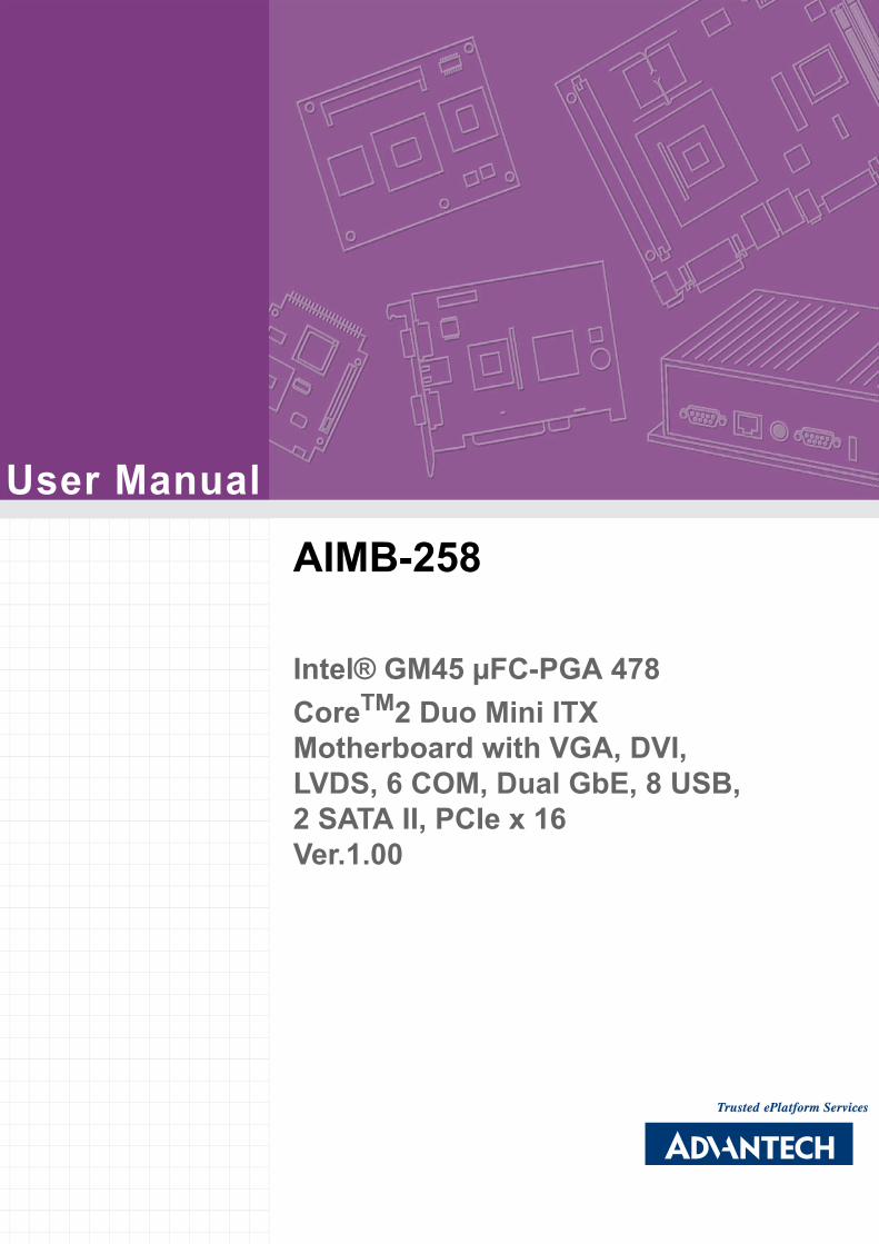
User Manual AIMB-258 Intelfi GM45 FC-PGA 478 Core TM 2 Duo Mini ITX Motherboard with VGA, DVI, LVDS, 6 COM, Dual GbE, 8 USB, 2 SATA II, PCIe x 16 Ver.1.00
User Manual
AIMB-258
Intel® GM45 µFC-PGA 478 CoreTM2 Duo Mini ITX Motherboard with VGA, DVI, LVDS, 6 COM, Dual GbE, 8 USB, 2 SATA II, PCIe x 16Ver.1.00
Safety Information
Electrical safety
! To prevent electrical shock hazard, disconnect the power cable from the electri-cal outlet before relocating the system.
! When adding or removing devices to or from the system, ensure that the power cables for the devices are unplugged before the signal cables are connected. If possible, disconnect all power cables from the existing system before you add a device.
! Before connecting or removing signal cables from the motherboard, ensure that all power cables are unplugged.
! Seek professional assistance before using an adapter or extension cord. These devices could interrupt the grounding circuit.
! Make sure that your power supply is set to the correct voltage in your area. If you are not sure about the voltage of the electrical outlet you are using, contact your local power company.
! If the power supply is broken, do not try to fix it by yourself. Contact a qualified service technician or your retailer.
Operation safety
! Before installing the motherboard and adding devices on it, carefully read all the manuals that came with the package.
! Before using the product, make sure all cables are correctly connected and the power cables are not damaged. If you detect any damage, contact your dealer immediately.
! To avoid short circuits, keep paper clips, screws, and staples away from connec-tors, slots, sockets and circuitry.
! Avoid dust, humidity, and temperature extremes. Do not place the product in any area where it may become wet.
! Place the product on a stable surface.! If you encounter technical problems with the product, contact a qualified service
technician or your retailer.
Part No. 2006025801 Edition 2
Printed in Taiwan June 2009
Caution! The symbol of the crossed out wheeled bin indicates that the product(electrical and electronic equipment) should not be placed in municipalwaste. Check local regulations for disposal of electronic products.
AIMB-258 User Manual ii

This device complies with the requirements in part 15 of the FCC rules: Operation issubject to the following two conditions:! This device may not cause harmful interference,! This device must accept any interference received, including interference that
may cause undesired operation.
This equipment has been tested and found to comply with the limits for a Class A dig-ital device, pursuant to Part 15 of the FCC Rules. These limits are designed to pro-vide reasonable protection against harmful interference when the equipment isoperated in a commercial environment. This equipment generates, uses, and canradiate radio frequency energy and, if not installed and used in accordance with theinstruction manual, may cause harmful interference to radio communications. Opera-tion of this device in a residential area is likely to cause harmful interference in whichcase the user will be required to correct the interference at his/her own expense. Theuser is advised that any equipment changes or modifications not expressly approvedby the party responsible for compliance would void the compliance to FCC regula-tions and therefore, the user's authority to operate the equipment.
Caution! There is a danger of a new battery exploding if it is incorrectly installed. Do not attempt to recharge, force open, or heat the battery. Replace the battery only with the same or equivalent type recommended by the man-ufacturer. Discard used batteries according to the manufacturer's instructions.
iii AIMB-258 User Manual
Technical SupportIf a problem arises with your system and no solution can be obtained from the user�smanual, please contact your place of purchase or local distributor. Alternatively,please try the following help resources for further guidance. Visit the Advantech web-site for FAQ, technical guide, BIOS updates, driver updates, and other information: http://support.advantech.com.tw/Support/default.aspx
Packing ListBefore you begin installing your single board, please make sure that the followingmaterials have been shipped:! 1 x AIMB-258 Intel® µFC-PGA 478 Core 2 Duo Mini ITX Motherboard! 2 x SATA HDD cable! 2 x SATA Power cable! 1 x Serial port cable 1 to 4! 1 x I/O port bracket! 1 x Startup manual! 1 x Driver CD! 1 x Warranty cardIf any of the above items is damaged or missing, please contact your retailer.
AIMB-258 User Manual iv
1.1 Before You Proceed.................................................................................. 21.2 Motherboard Overview.............................................................................. 2
1.2.1 Placement Direction...................................................................... 21.2.2 Screw Holes.................................................................................. 3
1.3 Motherboard Layout .................................................................................. 4Figure 1.1 Motherboard Layout ................................................... 4
1.4 Specifications ............................................................................................ 51.5 Operating System support list ................................................................... 61.6 Board Diagram .......................................................................................... 71.7 Ordering Information ................................................................................. 81.8 Riser Card ................................................................................................. 81.9 Bracket View ............................................................................................. 8
1.10 Accessories............................................................................................... 81.11 Layout Content List ................................................................................... 9
Table 1.1: Jumper Setting List..................................................... 9Table 1.2: JSETCOM1: COM1/+5 V/+12 V Selection ................. 9Table 1.3: JSETCOM2: COM2 RS232/422/485 Mode Selection 9Table 1.4: CMOS1: Clear CMOS .............................................. 10Table 1.5: J1:LCD Power 3.3 V/5.5 V Selection........................ 10Table 1.6: PSON1: ATX, AT Mode Selection ............................ 10Table 1.7: JWDT1: Watchdog Timer Output Option.................. 11Table 1.8: JOBS: HW monitor ................................................... 11
1.12 Central Processing Unit (CPU) for AIMB-258 ......................................... 111.12.1 Installing the CPU ....................................................................... 121.12.2 Installing the CPU Heatsink and Fan .......................................... 141.12.3 Uninstalling the CPU Heatsink and Fan...................................... 16
1.13 System Memory ...................................................................................... 171.13.1 DIMM Sockets Location .............................................................. 171.13.2 System Memory .......................................................................... 171.13.3 Memory Support List................................................................... 18
Table 1.9: SODIMM DDR3 ........................................................ 181.14 Connectors.............................................................................................. 19
1.14.1 Rear Panel Connectors............................................................... 19Table 1.10:Rear Panel Connectors ............................................ 19Table 1.11:LEDs......................................................................... 19
1.14.2 CPU Fan Connector (CPUFAN1) ............................................... 201.14.3 System Fan Connector (SYSFAN1, SYSFAN2) ......................... 211.14.4 Serial Port Connector 3456 (COM3456)..................................... 221.14.5 Front Headphone Connector (HD1)............................................ 221.14.6 Front Panel Connector (JFP1/JFP2/JFP3) ................................. 231.14.7 ATX soft power switch (JFP1 / PWR_SW) ................................. 231.14.8 Reset (JFP1 / RESET)................................................................ 231.14.9 HDD LED (JFP2 / HDDLED)....................................................... 231.14.10External speaker (JFP2 / SPEAKER) ......................................... 231.14.11Power LED and keyboard lock connector
(JFP3 / PWR_LED&KEY LOCK) ................................................ 24Table 1.12:ATX power supply LED status
(No support for AT power) ........................................ 241.14.12USB 2.0 Connector (USB56, USB78)......................................... 241.14.13ATX Power Connector (ATX1).................................................... 251.14.14LCD Inverter Connector (VP1).................................................... 261.14.15LVDS Connector (LVDS1) .......................................................... 261.14.16Digital I/O Connector (DIO_CN1)................................................ 27
v AIMB-258 User Manual
1.14.17Serial ATA Connector 1 & 2 (SATA1, SATA2) ........................... 271.14.18PCIe x 16 Slot (PCIE X 16)......................................................... 281.14.19SPI Flash Connector(SPI_CN1) ................................................. 281.14.20Memory Connector Channel A/B(DIMM1/2) ............................... 291.14.21SPDIF1 out connector(SPDIF1) ................................................. 291.14.22CF connector .............................................................................. 30
Chapter 2 BIOS Operation ................................. 312.1 BIOS Introduction.................................................................................... 322.2 BIOS Setup ............................................................................................. 32
2.2.1 Main Menu.................................................................................. 332.2.2 Standard CMOS Features .......................................................... 342.2.3 Advanced BIOS Features ........................................................... 352.2.4 Advanced Chipset Features ....................................................... 362.2.5 Integrated Peripherals ................................................................ 372.2.6 USE Device Setting .................................................................... 392.2.7 Power Management Setup ......................................................... 402.2.8 PnP/PCI Configurations.............................................................. 422.2.9 PC Health Status ........................................................................ 422.2.10 Load Setup Defaults ................................................................... 432.2.11 Set Password.............................................................................. 43
Chapter 3 Chipset Software Install Utility ........ 453.1 Before you Begin .................................................................................... 463.2 Introduction ............................................................................................. 463.3 Windows Vista/XP Driver Setup.............................................................. 47
Chapter 4 VGA Setup ......................................... 494.1 Introduction ............................................................................................. 504.2 Windows Vista/XP Driver Setup.............................................................. 50
Chapter 5 LAN Configuration ............................ 515.1 Introduction ............................................................................................. 525.2 Features.................................................................................................. 525.3 Installation............................................................................................... 525.4 Windows Vista/XP Driver Setup (Realtek RTL8111C)............................ 52
Appendix A Programming the Watchdog Timer . 55A.1 Programming the Watchdog Timer ......................................................... 56
A.1.1 Watchdog timer overview ........................................................... 56A.1.2 Programming the Watchdog Timer............................................. 56
Table A.1: Watchdog Timer Registers....................................... 58A.1.3 Example Program....................................................................... 59
Appendix B Pin Assignments............................... 63B.1 USB Connector (USB56,USB78)............................................................ 64
Table B.1: USB5/USB6 Connector (USB56) ............................. 64B.2 VGA Connector (VGA1A) ....................................................................... 64
Table B.2: VGA Connector (VGA1A)......................................... 64
AIMB-258 User Manual vi
B.3 DVI Connector (VGA1B) ......................................................................... 64Table B.3: DVI Connector (VGA1B)........................................... 64
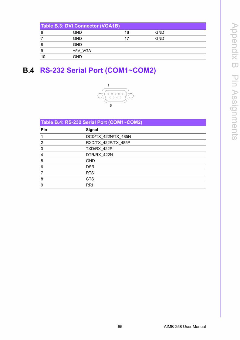
B.4 RS-232 Serial Port (COM1~COM2) ........................................................ 65Table B.4: RS-232 Serial Port (COM1~COM2) ......................... 65
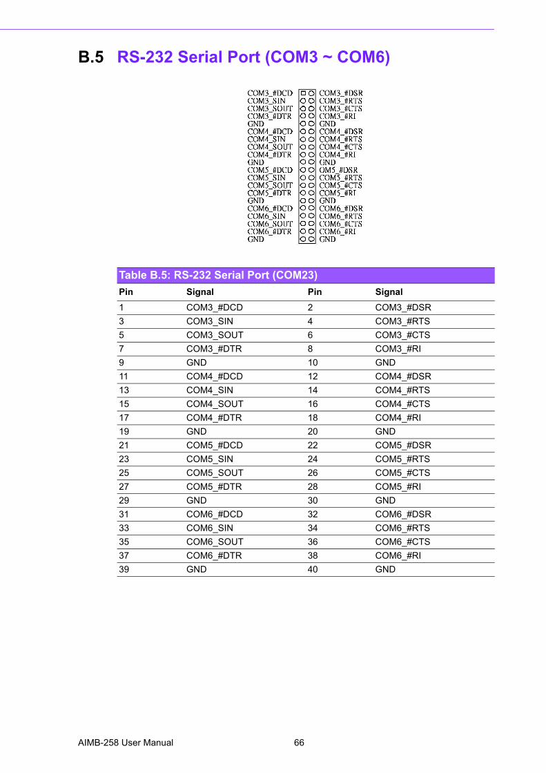
B.5 RS-232 Serial Port (COM3 ~ COM6) ...................................................... 66Table B.5: RS-232 Serial Port (COM23).................................... 66
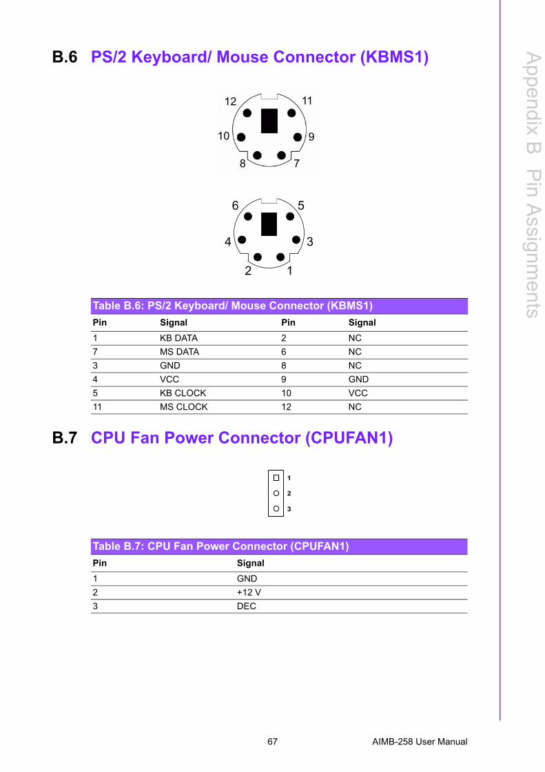
B.6 PS/2 Keyboard/ Mouse Connector (KBMS1) .......................................... 67Table B.6: PS/2 Keyboard/ Mouse Connector (KBMS1) ........... 67
B.7 CPU Fan Power Connector (CPUFAN1) ................................................ 67Table B.7: CPU Fan Power Connector (CPUFAN1).................. 67
B.8 Power LED & Keyboard Lock Connector (JFP3) .................................... 68Table B.8: Power LED and Keylock Connector (JFP3) ............ 68
B.9 HDD LED and External Speaker Connector(JFP2/HDD LED and SPEAKER)............................................................ 68
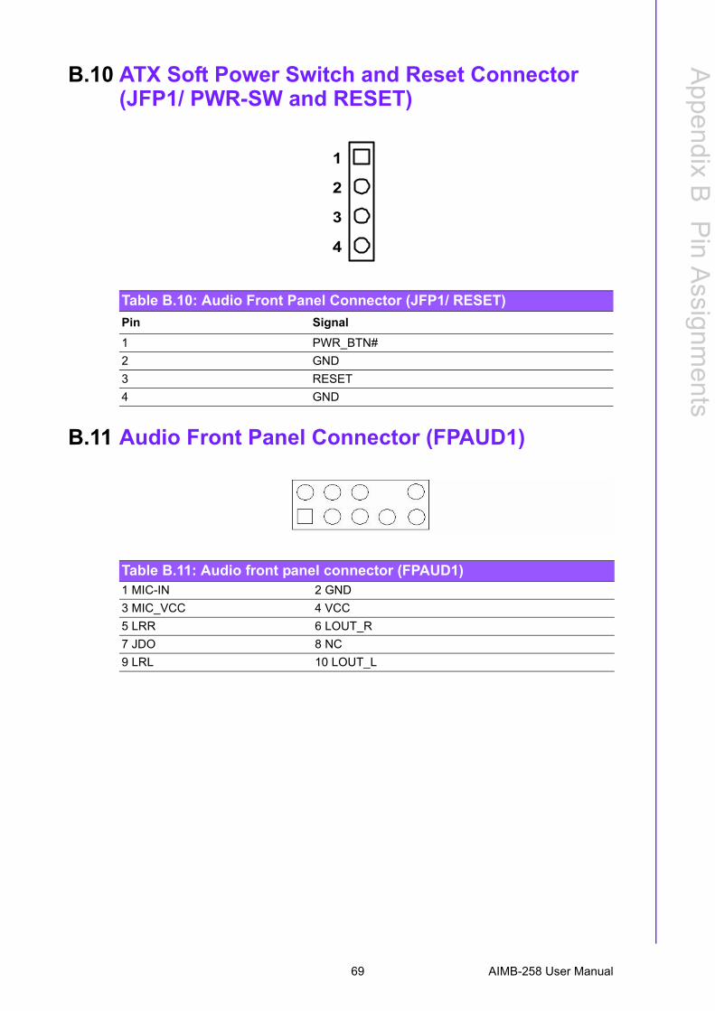
Table B.9: External Speaker Connector (JFP2/SPEAKER)....... 68B.10 ATX Soft Power Switch and Reset Connector
(JFP1/ PWR-SW and RESET) ................................................................ 69Table B.10:Audio Front Panel Connector (JFP1/ RESET) ......... 69
B.11 Audio Front Panel Connector (FPAUD1) ................................................ 69Table B.11:Audio front panel connector (FPAUD1) .................... 69
B.12 GPIO Pin Header (GPIO1)...................................................................... 70Table B.12:GPIO Pin Header (GPIO1) ....................................... 70
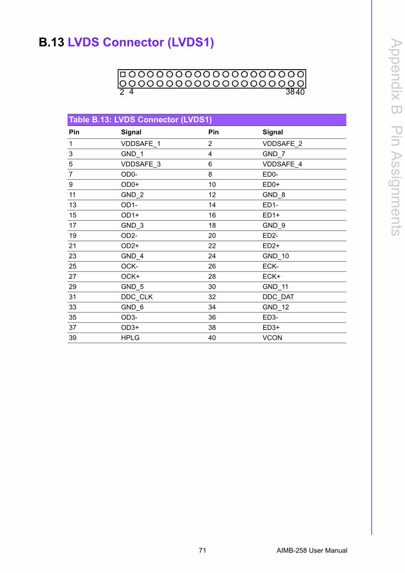
B.13 LVDS Connector (LVDS1) ...................................................................... 71Table B.13:LVDS Connector (LVDS1)........................................ 71
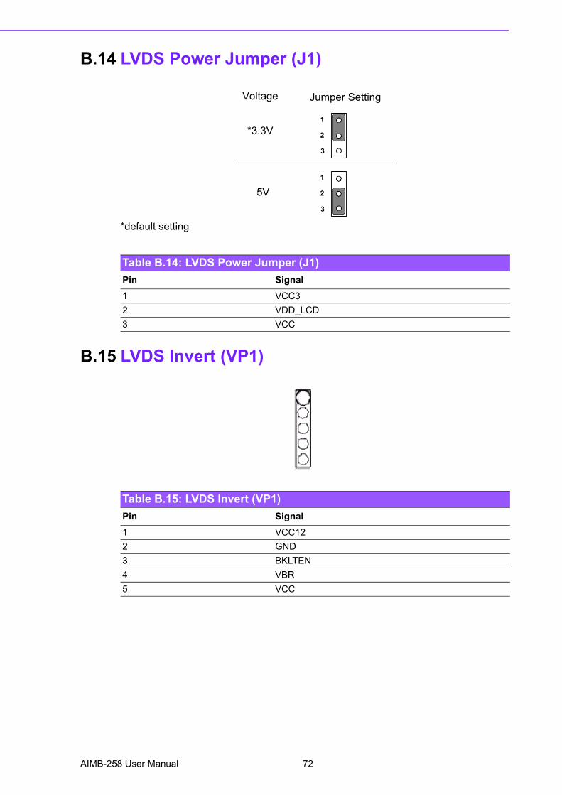
B.14 LVDS Power Jumper (J1) ....................................................................... 72Table B.14:LVDS Power Jumper (J1)......................................... 72
B.15 LVDS Invert (VP1)................................................................................... 72Table B.15:LVDS Invert (VP1) .................................................... 72
B.16 System I/O Ports ..................................................................................... 73Table B.16:System I/O Ports ...................................................... 73
B.17 DMA Channel Assignments .................................................................... 73Table B.17:DMA Channel Assignments...................................... 73
B.18 Interrupt Assignments ............................................................................. 74Table B.18:Interrupt Assignments............................................... 74
B.19 1st MB Memory Map ............................................................................... 74Table B.19:1st MB Memory Map ................................................ 74
vii AIMB-258 User Manual

AIMB-258 User Manual viii

Chapter 1
1 Product IntroductionThis chapter describes the main board features and the new tech-nologies it supports.
1.1 Before You ProceedTake note of the following precautions before you install motherboard components orchange any motherboard settings.
1.2 Motherboard OverviewBefore you install the motherboard, study the configuration of your chassis to ensurethat the motherboard fits into it. Refer to the chassis documentation before installingthe motherboard.
1.2.1 Placement DirectionWhen installing the motherboard, make sure that you place it into the chassis in thecorrect orientation. The edge with external ports goes to the rear part of the chassis.
Caution! ! Unplug the power cord from the wall socket before touching any component.
! Use a grounded wrist strap or touch a safely grounded object or a metal object, such as the power supply case, before handling com-ponents to avoid damaging them due to static electricity
! Hold components by the edges to avoid touching the ICs on them.! Whenever you uninstall any component, place it on a grounded
antistatic pad or in the bag that came with the component.! Before you install or remove any component, ensure that the ATX
power supply is switched off or the power cord is detached from the power supply. Failure to do so may cause severe damage to the motherboard, peripherals, and/or components.
Warning! Make sure to unplug the power cord before installing or removing the motherboard. Failure to do so can cause you physical injury and dam-age motherboard components.
AIMB-258 User Manual 2
Chapter 1
ProductIntroduction
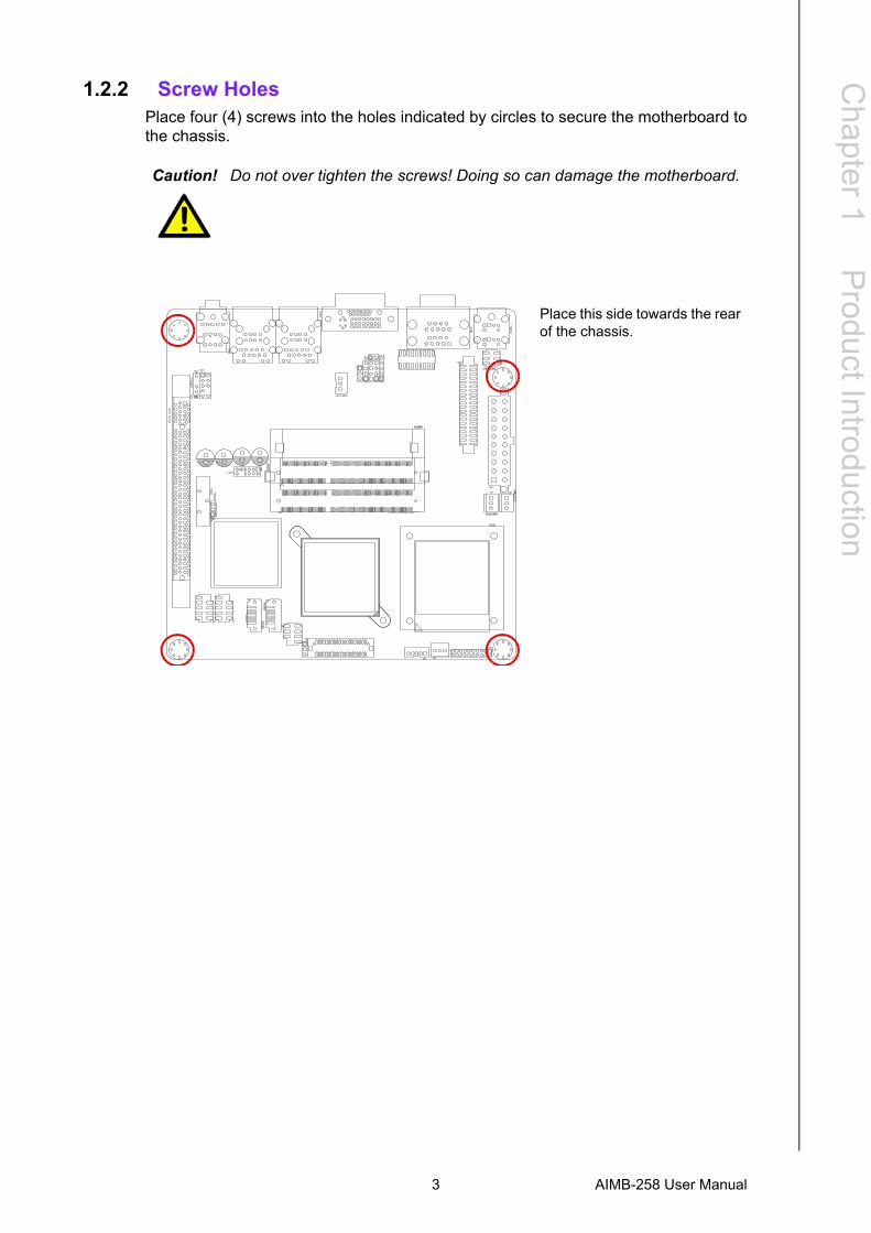
1.2.2 Screw HolesPlace four (4) screws into the holes indicated by circles to secure the motherboard tothe chassis.
Caution! Do not over tighten the screws! Doing so can damage the motherboard.
Place this side towards the rear of the chassis.
3 AIMB-258 User Manual
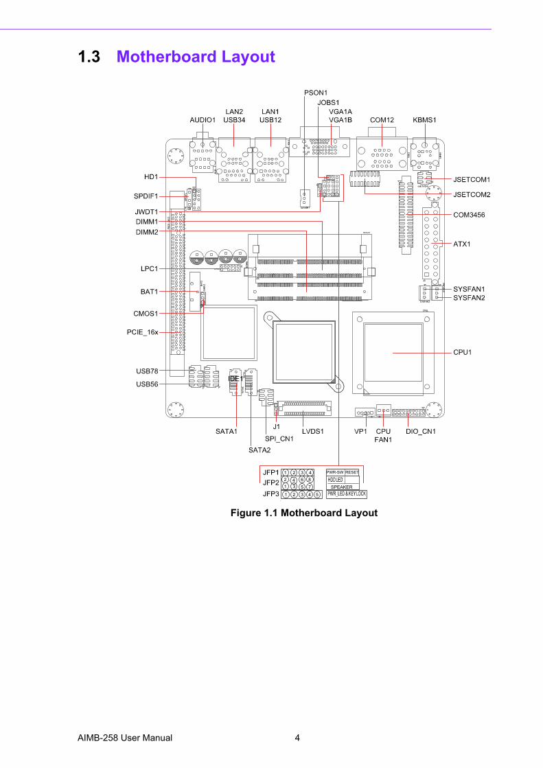
1.3 Motherboard Layout
Figure 1.1 Motherboard Layout
PWR-SW RESET
SPEAKER
1 2 3 42 4 6 81 3 5 71 2 3 4 5
AIMB-258 User Manual 4
Chapter 1
ProductIntroduction
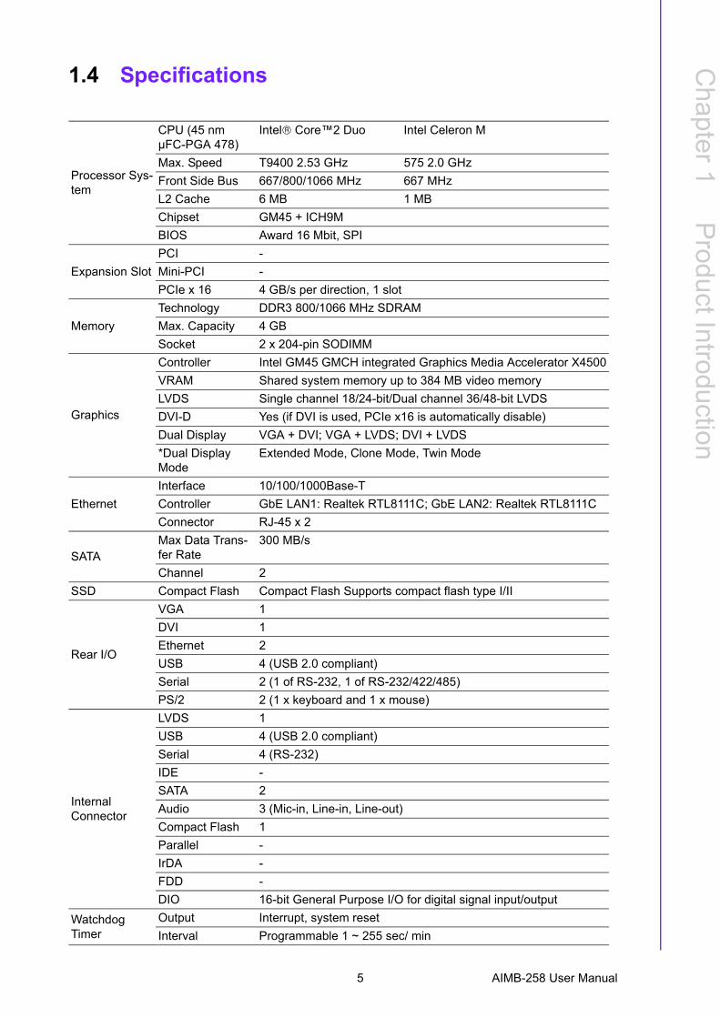
1.4 Specifications
Processor Sys-tem
CPU (45 nm µFC-PGA 478)
Intel® Core�2 Duo Intel Celeron M
Max. Speed T9400 2.53 GHz 575 2.0 GHzFront Side Bus 667/800/1066 MHz 667 MHzL2 Cache 6 MB 1 MBChipset GM45 + ICH9MBIOS Award 16 Mbit, SPI
Expansion SlotPCI -Mini-PCI -PCIe x 16 4 GB/s per direction, 1 slot
MemoryTechnology DDR3 800/1066 MHz SDRAMMax. Capacity 4 GBSocket 2 x 204-pin SODIMM
Graphics
Controller Intel GM45 GMCH integrated Graphics Media Accelerator X4500VRAM Shared system memory up to 384 MB video memoryLVDS Single channel 18/24-bit/Dual channel 36/48-bit LVDSDVI-D Yes (if DVI is used, PCIe x16 is automatically disable)Dual Display VGA + DVI; VGA + LVDS; DVI + LVDS*Dual Display Mode
Extended Mode, Clone Mode, Twin Mode
EthernetInterface 10/100/1000Base-TController GbE LAN1: Realtek RTL8111C; GbE LAN2: Realtek RTL8111CConnector RJ-45 x 2
SATAMax Data Trans-fer Rate
300 MB/s
Channel 2SSD Compact Flash Compact Flash Supports compact flash type I/II
Rear I/O
VGA 1DVI 1Ethernet 2USB 4 (USB 2.0 compliant)Serial 2 (1 of RS-232, 1 of RS-232/422/485)PS/2 2 (1 x keyboard and 1 x mouse)
Internal Connector
LVDS 1USB 4 (USB 2.0 compliant)Serial 4 (RS-232)IDE -SATA 2Audio 3 (Mic-in, Line-in, Line-out)Compact Flash 1Parallel -IrDA -FDD -DIO 16-bit General Purpose I/O for digital signal input/output
Watchdog Timer
Output Interrupt, system resetInterval Programmable 1 ~ 255 sec/ min
5 AIMB-258 User Manual
*Dual Display Clone uses both display pipes to drive the same content at the sameresolution and color depth to two different displays. This configuration allows for dif-ferent refresh rates on each display.Dual Display Twin uses one of the display pipes to drive the same content, at thesame resolution, color depth, and refresh rates to two different displays.Extended Desktop uses both display pipes to drive different content, at potentiallydifferent resolutions, refresh rates, and color depths, to two different displays. Thisconfiguration allows for a larger Windows desktop by using both displays as onework surface.
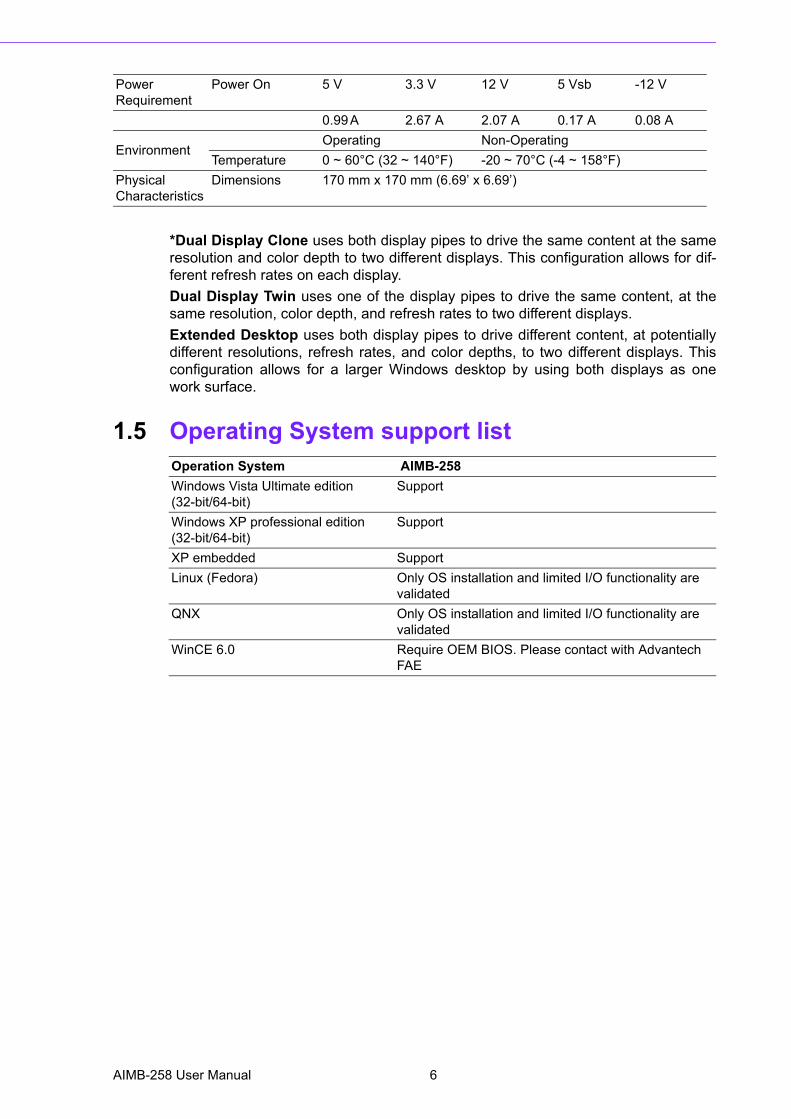
1.5 Operating System support list
Power Requirement
Power On 5 V 3.3 V 12 V 5 Vsb -12 V
0.99 A 2.67 A 2.07 A 0.17 A 0.08 A
EnvironmentOperating Non-Operating
Temperature 0 ~ 60°C (32 ~ 140°F) -20 ~ 70°C (-4 ~ 158°F)Physical Characteristics
Dimensions 170 mm x 170 mm (6.69� x 6.69�)
Operation System AIMB-258Windows Vista Ultimate edition(32-bit/64-bit)
Support
Windows XP professional edition(32-bit/64-bit)
Support
XP embedded Support Linux (Fedora) Only OS installation and limited I/O functionality are
validatedQNX Only OS installation and limited I/O functionality are
validatedWinCE 6.0 Require OEM BIOS. Please contact with Advantech
FAE
AIMB-258 User Manual 6
Chapter 1
ProductIntroduction
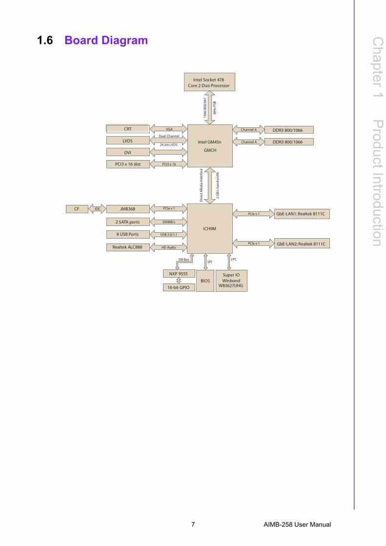
1.6 Board Diagram
Intel GM45n
GMCH
CRT
BIOS
NXP 9555
16-bit GPIO
Super IOWinbond
W83627UHG
Dir
ectM
edia
Inte
rfac
e
2G
B/s
ban
dw
idth
ICH9M
1066
/800
/66 7
MH
zFS
B
VGA
PCI3 x 16
DDR3 800/1066Channel A
LVDSDual Channel
24-bit LVDS
GbE-LAN1: Realtek 8111C
SPI
DVI
PCI3 x 16 slot
LPCSM Bus
JMB368
2 SATA ports
8 USB Ports
Realtek ALC888
300MB/s
PCIe x 1CF IDE
PCIe x 1
PCIe x 1
USB 2.0/1.1
HD Audio
Intel Socket 478Core 2 Duo Processor
DDR3 800/1066Channel A
GbE-LAN2: Realtek 8111C
7 AIMB-258 User Manual
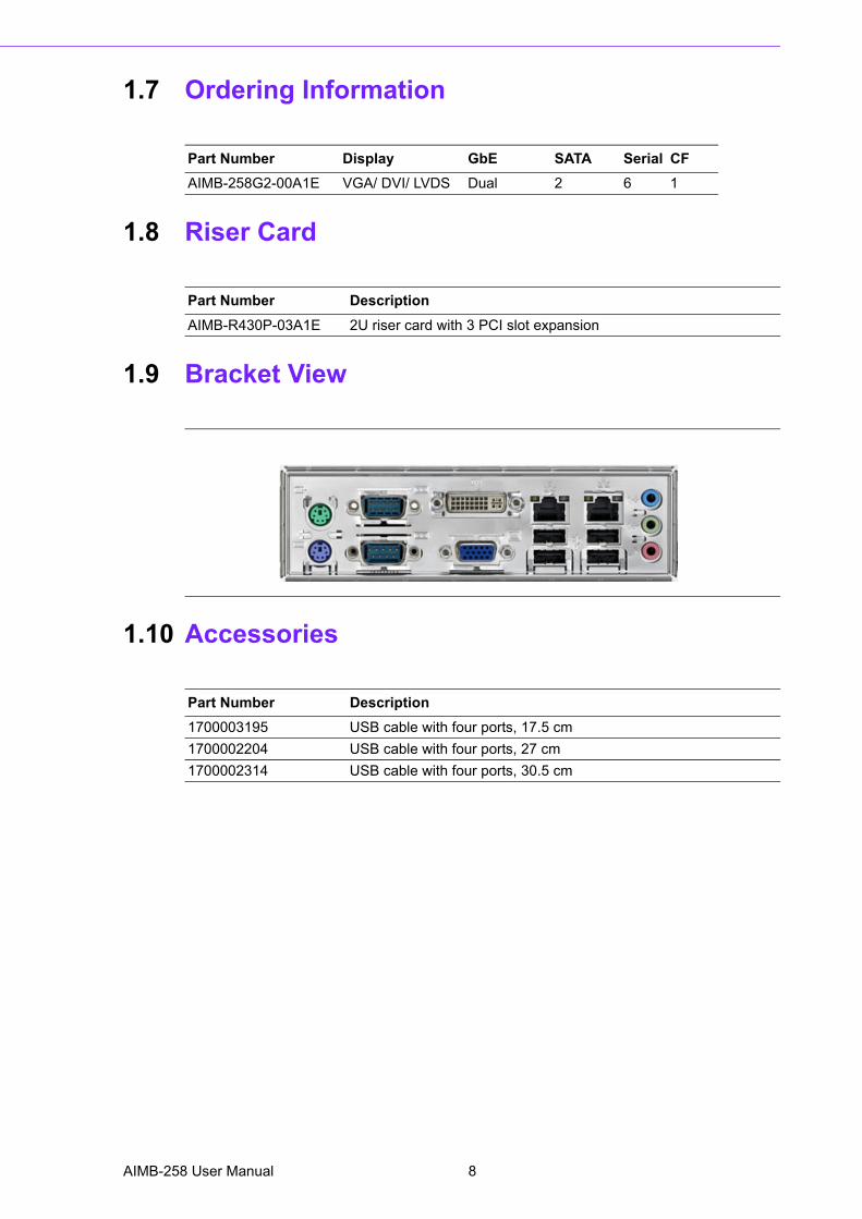
1.7 Ordering Information
1.8 Riser Card
1.9 Bracket View
1.10 Accessories
Part Number Display GbE SATA Serial CFAIMB-258G2-00A1E VGA/ DVI/ LVDS Dual 2 6 1
Part Number DescriptionAIMB-R430P-03A1E 2U riser card with 3 PCI slot expansion
Part Number Description1700003195 USB cable with four ports, 17.5 cm1700002204 USB cable with four ports, 27 cm1700002314 USB cable with four ports, 30.5 cm
AIMB-258 User Manual 8
Chapter 1
ProductIntroduction
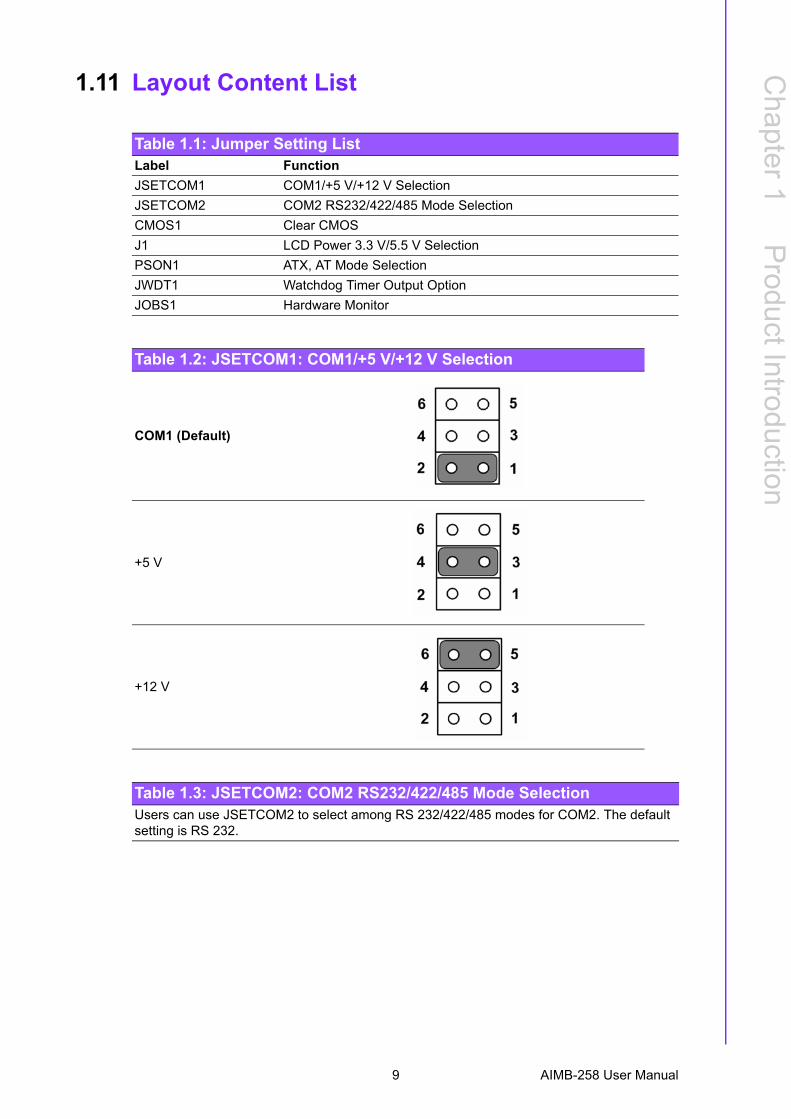
1.11 Layout Content List
Table 1.1: Jumper Setting ListLabel FunctionJSETCOM1 COM1/+5 V/+12 V SelectionJSETCOM2 COM2 RS232/422/485 Mode SelectionCMOS1 Clear CMOSJ1 LCD Power 3.3 V/5.5 V SelectionPSON1 ATX, AT Mode SelectionJWDT1 Watchdog Timer Output OptionJOBS1 Hardware Monitor
Table 1.2: JSETCOM1: COM1/+5 V/+12 V Selection
COM1 (Default)
+5 V
+12 V
Table 1.3: JSETCOM2: COM2 RS232/422/485 Mode SelectionUsers can use JSETCOM2 to select among RS 232/422/485 modes for COM2. The default setting is RS 232.
9 AIMB-258 User Manual
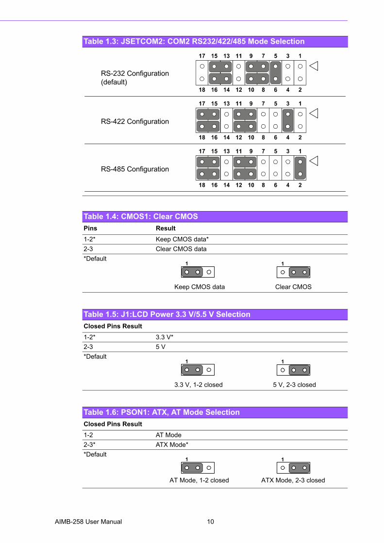
Table 1.4: CMOS1: Clear CMOSPins Result1-2* Keep CMOS data*2-3 Clear CMOS data*Default
Table 1.5: J1:LCD Power 3.3 V/5.5 V SelectionClosed Pins Result1-2* 3.3 V*2-3 5 V*Default
Table 1.6: PSON1: ATX, AT Mode SelectionClosed Pins Result1-2 AT Mode2-3* ATX Mode**Default
Table 1.3: JSETCOM2: COM2 RS232/422/485 Mode Selection
RS-232 Configuration(default)
RS-422 Configuration
RS-485 Configuration
1 1
Keep CMOS data Clear CMOS
1 1
3.3 V, 1-2 closed 5 V, 2-3 closed
1 1
AT Mode, 1-2 closed ATX Mode, 2-3 closed
AIMB-258 User Manual 10
Chapter 1
ProductIntroduction
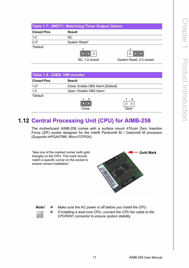
1.12 Central Processing Unit (CPU) for AIMB-258The motherboard AIMB-258 comes with a surface mount 478-pin Zero InsertionForce (ZIF) socket designed for the Intel® Pentium® M / Celeron® M processor(Supports mPGA478M, Micro-FCPGA).
Table 1.7: JWDT1: Watchdog Timer Output OptionClosed Pins Result1-2 NC2-3* System Reset**Default
Table 1.8: JOBS: HW monitorClosed Pins Result1-2* Close: Enable OBS Alarm [Default]1-2 Open: Disable OBS Alarm*Default
1 1
NC, 1-2 closed System Reset, 2-3 closed
Close Open
1 2 1 2
Take one of the marked corner (with gold triangle) on the CPU. This mark should match a specific corner on the socket to ensure correct installation.
Note! ! Make sure the AC power is off before you install the CPU.! If installing a dual-core CPU, connect the CPU fan cable to the
CPUFAN1 connector to ensure system stability.
Gold Mark
11 AIMB-258 User Manual
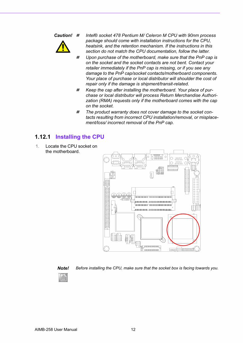
1.12.1 Installing the CPU
Caution! ! Intel® socket 478 Pentium M/ Celeron M CPU with 90nm process package should come with installation instructions for the CPU, heatsink, and the retention mechanism. If the instructions in this section do not match the CPU documentation, follow the latter.
! Upon purchase of the motherboard, make sure that the PnP cap is on the socket and the socket contacts are not bent. Contact your retailer immediately if the PnP cap is missing, or if you see any damage to the PnP cap/socket contacts/motherboard components. Your place of purchase or local distributor will shoulder the cost of repair only if the damage is shipment/transit-related.
! Keep the cap after installing the motherboard. Your place of pur-chase or local distributor will process Return Merchandise Authori-zation (RMA) requests only if the motherboard comes with the cap on the socket.
! The product warranty does not cover damage to the socket con-tacts resulting from incorrect CPU installation/removal, or misplace-ment/loss/ incorrect removal of the PnP cap.
1. Locate the CPU socket on the motherboard.
Note! Before installing the CPU, make sure that the socket box is facing towards you.
AIMB-258 User Manual 12
Chapter 1
ProductIntroduction
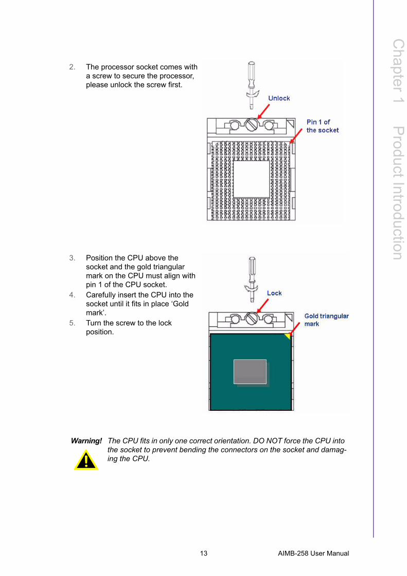
2. The processor socket comes with a screw to secure the processor, please unlock the screw first.
3. Position the CPU above the socket and the gold triangular mark on the CPU must align with pin 1 of the CPU socket.
4. Carefully insert the CPU into the socket until it fits in place �Gold mark�.
5. Turn the screw to the lock position.
Warning! The CPU fits in only one correct orientation. DO NOT force the CPU into the socket to prevent bending the connectors on the socket and damag-ing the CPU.
13 AIMB-258 User Manual
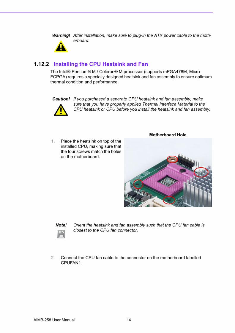
1.12.2 Installing the CPU Heatsink and FanThe Intel® Pentium® M / Celeron® M processor (supports mPGA478M, Micro-FCPGA) requires a specially designed heatsink and fan assembly to ensure optimum thermal condition and performance.
Warning! After installation, make sure to plug-in the ATX power cable to the moth-erboard.
Caution! If you purchased a separate CPU heatsink and fan assembly, make sure that you have properly applied Thermal Interface Material to the CPU heatsink or CPU before you install the heatsink and fan assembly.
1. Place the heatsink on top of the installed CPU, making sure that the four screws match the holes on the motherboard.
Motherboard Hole
Note! Orient the heatsink and fan assembly such that the CPU fan cable is closest to the CPU fan connector.
2. Connect the CPU fan cable to the connector on the motherboard labelled CPUFAN1.
AIMB-258 User Manual 14
Chapter 1
ProductIntroduction
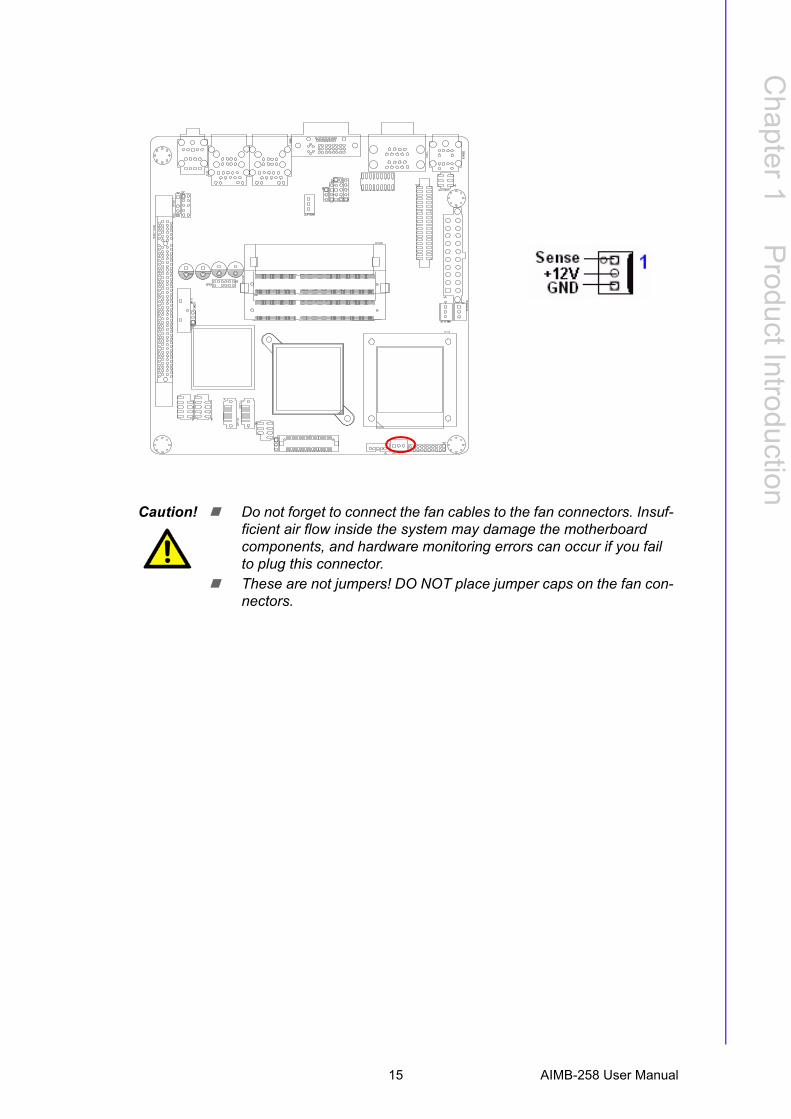
Caution! ! Do not forget to connect the fan cables to the fan connectors. Insuf-ficient air flow inside the system may damage the motherboard components, and hardware monitoring errors can occur if you fail to plug this connector.
! These are not jumpers! DO NOT place jumper caps on the fan con-nectors.
15 AIMB-258 User Manual
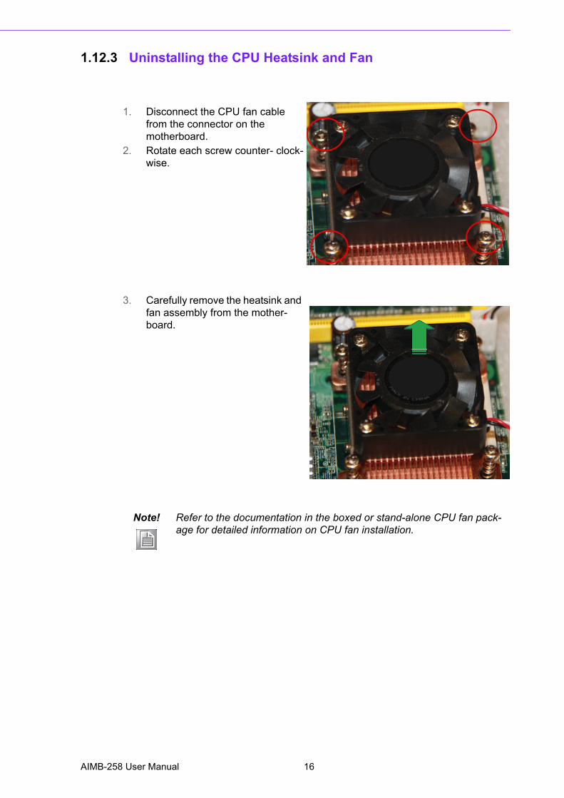
1.12.3 Uninstalling the CPU Heatsink and Fan
1. Disconnect the CPU fan cable from the connector on the motherboard.
2. Rotate each screw counter- clock-wise.
3. Carefully remove the heatsink and fan assembly from the mother-board.
Note! Refer to the documentation in the boxed or stand-alone CPU fan pack-age for detailed information on CPU fan installation.
AIMB-258 User Manual 16
Chapter 1
ProductIntroduction
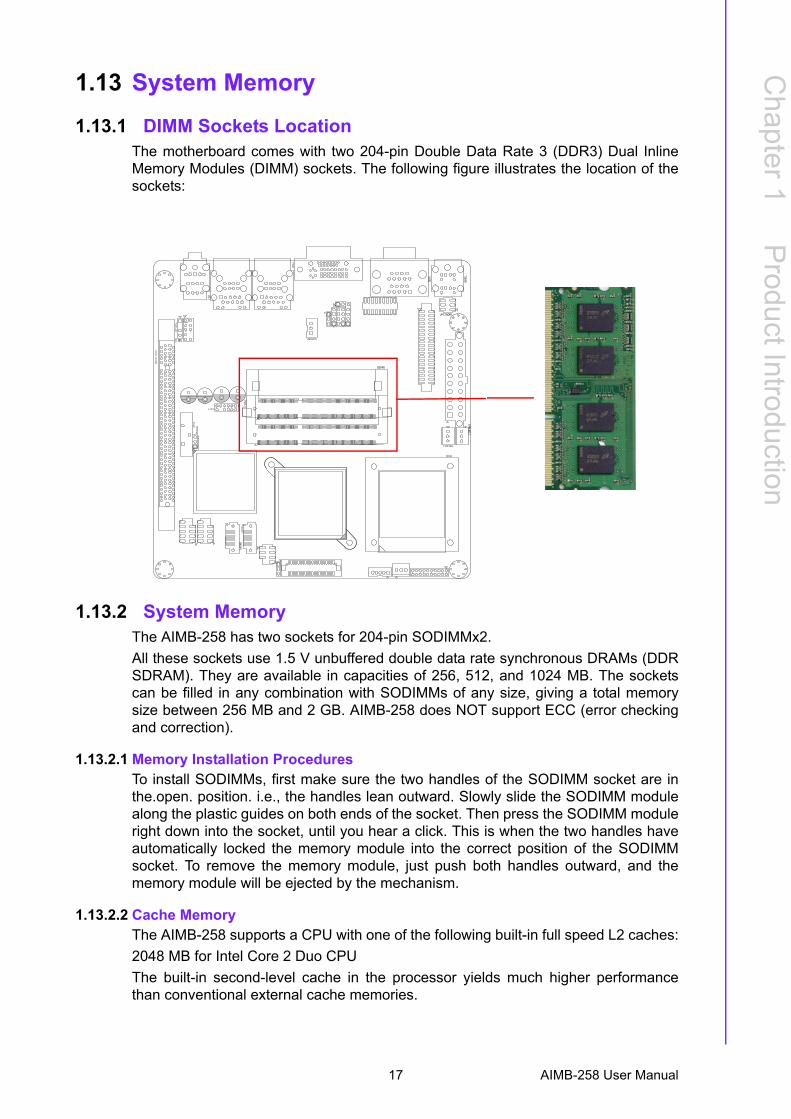
1.13 System Memory
1.13.1 DIMM Sockets LocationThe motherboard comes with two 204-pin Double Data Rate 3 (DDR3) Dual InlineMemory Modules (DIMM) sockets. The following figure illustrates the location of thesockets:
1.13.2 System MemoryThe AIMB-258 has two sockets for 204-pin SODIMMx2.All these sockets use 1.5 V unbuffered double data rate synchronous DRAMs (DDRSDRAM). They are available in capacities of 256, 512, and 1024 MB. The socketscan be filled in any combination with SODIMMs of any size, giving a total memorysize between 256 MB and 2 GB. AIMB-258 does NOT support ECC (error checkingand correction).
1.13.2.1 Memory Installation ProceduresTo install SODIMMs, first make sure the two handles of the SODIMM socket are inthe.open. position. i.e., the handles lean outward. Slowly slide the SODIMM modulealong the plastic guides on both ends of the socket. Then press the SODIMM moduleright down into the socket, until you hear a click. This is when the two handles haveautomatically locked the memory module into the correct position of the SODIMMsocket. To remove the memory module, just push both handles outward, and thememory module will be ejected by the mechanism.
1.13.2.2 Cache MemoryThe AIMB-258 supports a CPU with one of the following built-in full speed L2 caches:2048 MB for Intel Core 2 Duo CPUThe built-in second-level cache in the processor yields much higher performancethan conventional external cache memories.
17 AIMB-258 User Manual

1.13.3 Memory Support List
Table 1.9: SODIMM DDR3SODIMM DDR3Brand Size Speed Type ECC Vendor PN Advantech
PNMemory
Transcend 1GB DDR3 1066
SODIMMDDR3
N TS128MSK64V1U
96SD3-1G1066NN-TR
SEC K4B1G0846D-HCF8(128x8)
2GB DDR3 1066
SODIMMDDR3
N TS256MSK64V1U
96SD3-2G1066NN-TR
SEC K4B1G0846D-HCF8(128x8)
Apacer RAMApacer 1GB DDR3
1066SODIMM DDR3
N NA NA ELPIDA J1108BABG-DJ-E 084909DE7
2GB DDR3 1066
SODIMM DDR3
N NA NA ELPIDA J1108BABG-DJ-E 084909D8T
AIMB-258 User Manual 18
Chapter 1
ProductIntroduction
1.14 Connectors
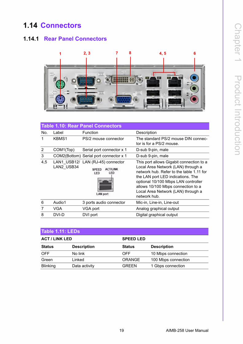
1.14.1 Rear Panel Connectors
Table 1.10: Rear Panel ConnectorsNo. Label Function Description1 KBMS1 PS/2 mouse connector The standard PS/2 mouse DIN connec-
tor is for a PS/2 mouse.2 COM1(Top) Serial port connector x 1 D-sub 9-pin, male3 COM2(Bottom) Serial port connector x 1 D-sub 9-pin, male4,5 LAN1_USB12/
LAN2_USB34LAN (RJ-45) connector This port allows Gigabit connection to a
Local Area Network (LAN) through a network hub. Refer to the table 1.11 for the LAN port LED indications. The optional 10/100 Mbps LAN controller allows 10/100 Mbps connection to a Local Area Network (LAN) through a network hub.
6 Audio1 3 ports audio connector Mic-in, Line-in, Line-out7 VGA VGA port Analog graphical output8 DVI-D DVI port Digital graphical output
Table 1.11: LEDsACT / LINK LED SPEED LED
Status Description Status DescriptionOFF No link OFF 10 Mbps connectionGreen Linked ORANGE 100 Mbps connectionBlinking Data activity GREEN 1 Gbps connection
1 2, 3 7 8 4, 5 6
19 AIMB-258 User Manual
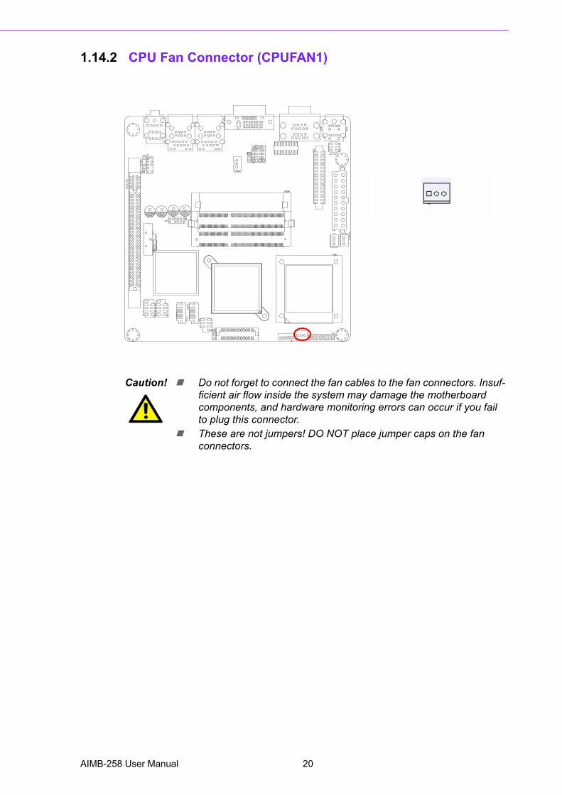
1.14.2 CPU Fan Connector (CPUFAN1)
Caution! ! Do not forget to connect the fan cables to the fan connectors. Insuf-ficient air flow inside the system may damage the motherboard components, and hardware monitoring errors can occur if you fail to plug this connector.
! These are not jumpers! DO NOT place jumper caps on the fan connectors.
AIMB-258 User Manual 20
Chapter 1
ProductIntroduction
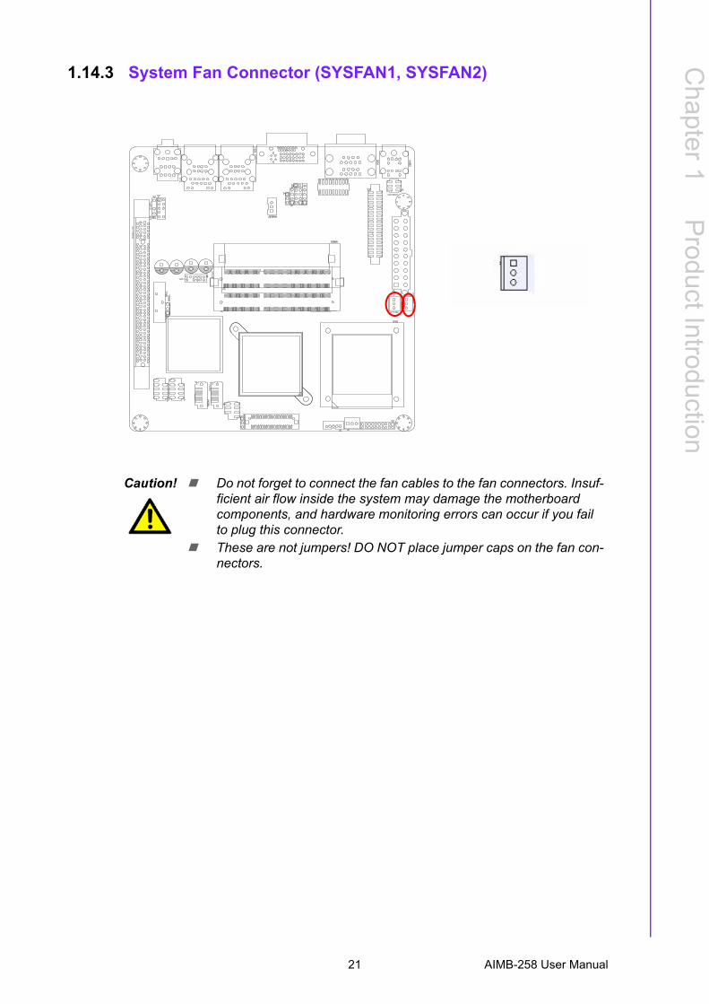
1.14.3 System Fan Connector (SYSFAN1, SYSFAN2)
Caution! ! Do not forget to connect the fan cables to the fan connectors. Insuf-ficient air flow inside the system may damage the motherboard components, and hardware monitoring errors can occur if you fail to plug this connector.
! These are not jumpers! DO NOT place jumper caps on the fan con-nectors.
21 AIMB-258 User Manual
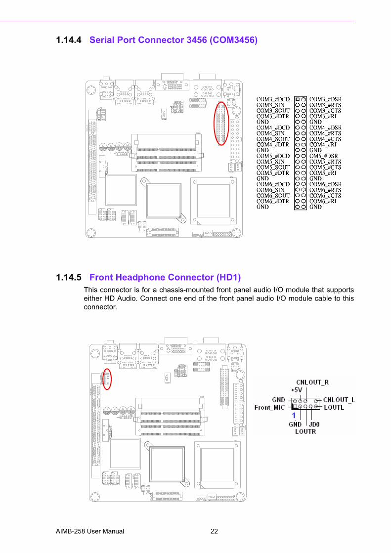
1.14.4 Serial Port Connector 3456 (COM3456)
1.14.5 Front Headphone Connector (HD1)This connector is for a chassis-mounted front panel audio I/O module that supportseither HD Audio. Connect one end of the front panel audio I/O module cable to thisconnector.
AIMB-258 User Manual 22
Chapter 1
ProductIntroduction
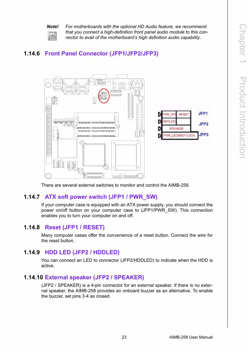
1.14.6 Front Panel Connector (JFP1/JFP2/JFP3)
There are several external switches to monitor and control the AIMB-258.
1.14.7 ATX soft power switch (JFP1 / PWR_SW)If your computer case is equipped with an ATX power supply, you should connect thepower on/off button on your computer case to (JFP1/PWR_SW). This connectionenables you to turn your computer on and off.
1.14.8 Reset (JFP1 / RESET)Many computer cases offer the convenience of a reset button. Connect the wire forthe reset button.
1.14.9 HDD LED (JFP2 / HDDLED)You can connect an LED to connector (JFP2/HDDLED) to indicate when the HDD isactive.
1.14.10 External speaker (JFP2 / SPEAKER)(JFP2 / SPEAKER) is a 4-pin connector for an external speaker. If there is no exter-nal speaker, the AIMB-258 provides an onboard buzzer as an alternative. To enablethe buzzer, set pins 3-4 as closed.
Note! For motherboards with the optional HD Audio feature, we recommend that you connect a high-definition front panel audio module to this con-nector to avail of the motherboard�s high definition audio capability.
23 AIMB-258 User Manual
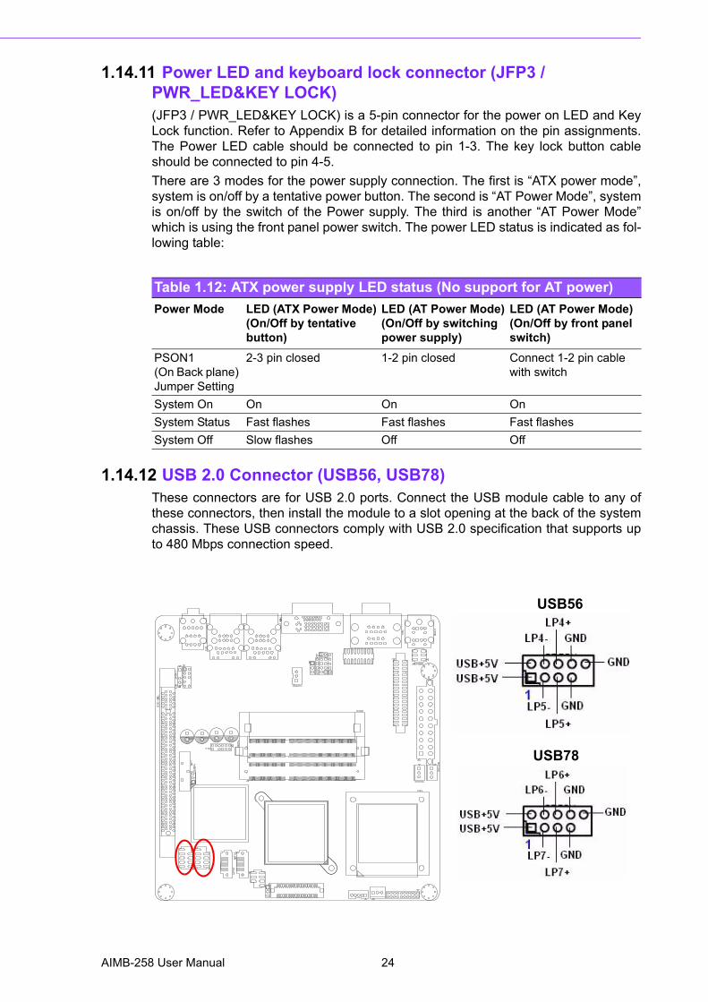
1.14.11 Power LED and keyboard lock connector (JFP3 / PWR_LED&KEY LOCK)(JFP3 / PWR_LED&KEY LOCK) is a 5-pin connector for the power on LED and KeyLock function. Refer to Appendix B for detailed information on the pin assignments.The Power LED cable should be connected to pin 1-3. The key lock button cableshould be connected to pin 4-5.There are 3 modes for the power supply connection. The first is �ATX power mode�,system is on/off by a tentative power button. The second is �AT Power Mode�, systemis on/off by the switch of the Power supply. The third is another �AT Power Mode�which is using the front panel power switch. The power LED status is indicated as fol-lowing table:
1.14.12 USB 2.0 Connector (USB56, USB78)These connectors are for USB 2.0 ports. Connect the USB module cable to any ofthese connectors, then install the module to a slot opening at the back of the systemchassis. These USB connectors comply with USB 2.0 specification that supports upto 480 Mbps connection speed.
Table 1.12: ATX power supply LED status (No support for AT power)Power Mode LED (ATX Power Mode)
(On/Off by tentative button)
LED (AT Power Mode)(On/Off by switching power supply)
LED (AT Power Mode)(On/Off by front panel switch)
PSON1 (On Back plane) Jumper Setting
2-3 pin closed 1-2 pin closed Connect 1-2 pin cable with switch
System On On On OnSystem Status Fast flashes Fast flashes Fast flashesSystem Off Slow flashes Off Off
USB56
USB78
AIMB-258 User Manual 24
Chapter 1
ProductIntroduction
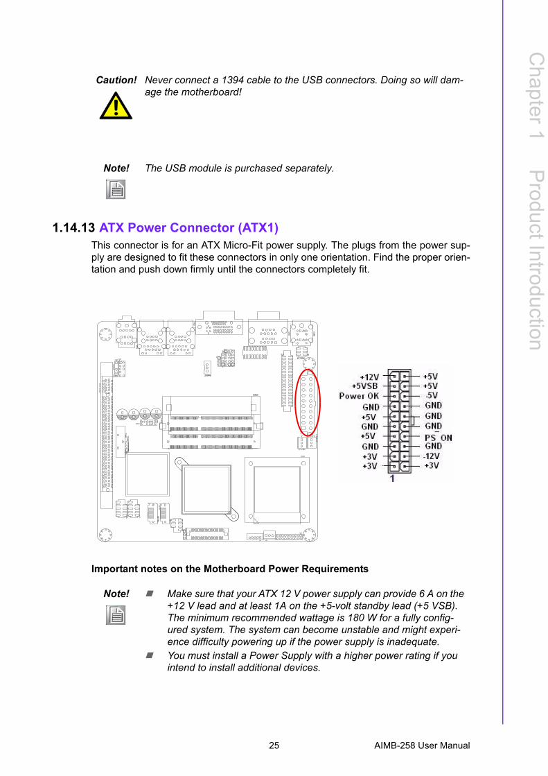
1.14.13 ATX Power Connector (ATX1)This connector is for an ATX Micro-Fit power supply. The plugs from the power sup-ply are designed to fit these connectors in only one orientation. Find the proper orien-tation and push down firmly until the connectors completely fit.
Important notes on the Motherboard Power Requirements
Caution! Never connect a 1394 cable to the USB connectors. Doing so will dam-age the motherboard!
Note! The USB module is purchased separately.
Note! ! Make sure that your ATX 12 V power supply can provide 6 A on the +12 V lead and at least 1A on the +5-volt standby lead (+5 VSB). The minimum recommended wattage is 180 W for a fully config-ured system. The system can become unstable and might experi-ence difficulty powering up if the power supply is inadequate.
! You must install a Power Supply with a higher power rating if you intend to install additional devices.
25 AIMB-258 User Manual
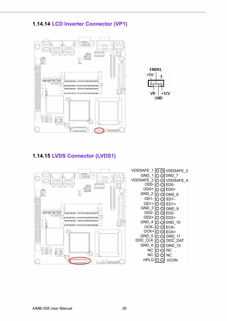
1.14.14 LCD Inverter Connector (VP1)
1.14.15 LVDS Connector (LVDS1)
VDDSAFE_1 VDDSAFE_2GND_1 GND_7
VDDSAFE_3 VDDSAFE_4OD0- ED0-
OD0+ ED0+GND_2 GND_8
OD1-OD1+
ED1-ED1+
GND_3 GND_9OD2-OD2+
ED2-ED2+
GND_4 GND_10OCK-OCK+
ECK-ECK+
GND_5 GND_11DDC_CLK DDC_DAT
GND_6 GND_12 NC NCHPLG
NCNCVCON
AIMB-258 User Manual 26
Chapter 1
ProductIntroduction
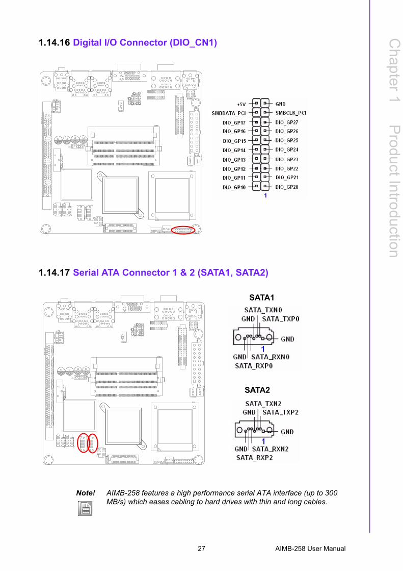
1.14.16 Digital I/O Connector (DIO_CN1)
1.14.17 Serial ATA Connector 1 & 2 (SATA1, SATA2)
SATA1
SATA2
Note! AIMB-258 features a high performance serial ATA interface (up to 300 MB/s) which eases cabling to hard drives with thin and long cables.
27 AIMB-258 User Manual
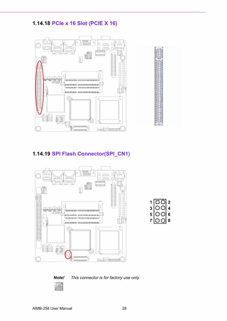
1.14.18 PCIe x 16 Slot (PCIE X 16)
1.14.19 SPI Flash Connector(SPI_CN1)
Note! This connector is for factory use only.
AIMB-258 User Manual 28
Chapter 1
ProductIntroduction
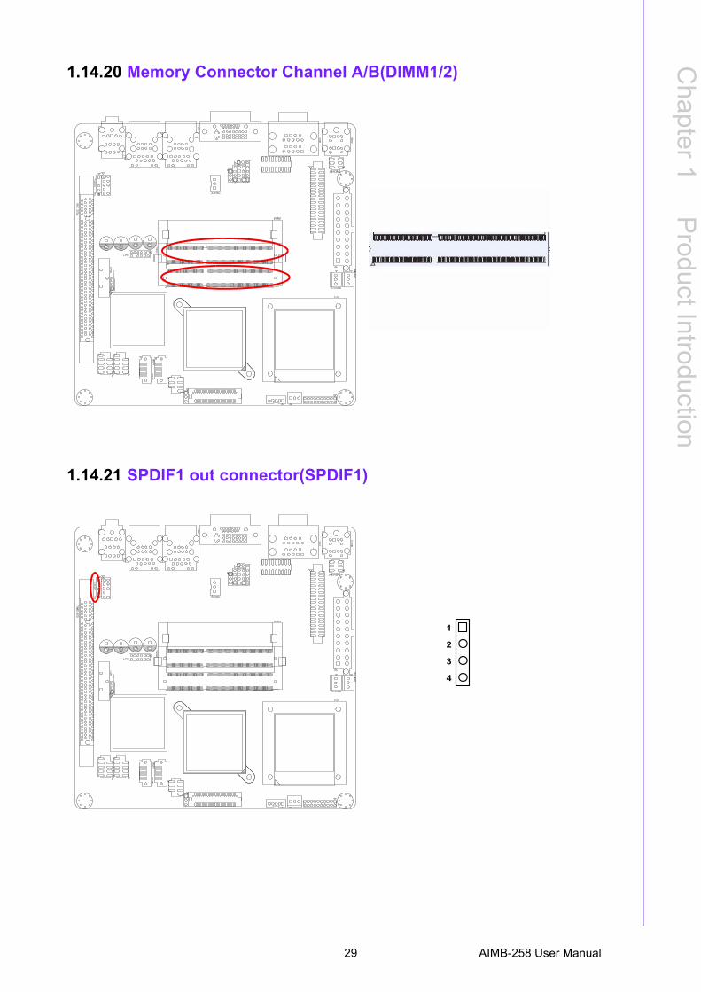
1.14.20 Memory Connector Channel A/B(DIMM1/2)
1.14.21 SPDIF1 out connector(SPDIF1)
1
2
4
3
29 AIMB-258 User Manual
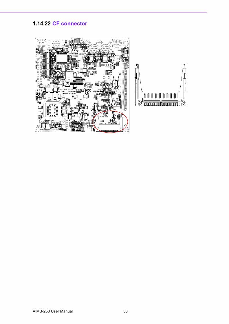
1.14.22 CF connector
AIMB-258 User Manual 30

Chapter 2
2 BIOS Operation
2.1 BIOS IntroductionAdvantech provides full-featured AwardBIOSes, which deliver the superior perfor-mance, compatibility, and functionality that today�s manufacturers of industrial PCsand embedded boards demand. The many options and extensions let you customizeyour products to a wide range of designs and target markets.The modular, adaptable AwardBIOS 6.0 supports the broadest range of third-partyperipherals and all popular chipsets, plus Intel®, AMD, nVidia, VIA, and compatibleCPUs from 386 through Pentium and AMD Geode, K7 and K8 (including multiple pro-cessor platforms), and VIA Eden C3 and C7 CPU.You can use Advantech�s utilities to select and install features to suit your exclusivedesigns.
2.2 BIOS SetupThe AIMB-258 Series system has built-in AwardBIOS with a CMOS SETUP utilitywhich allows user to configure required settings or to activate certain system fea-tures.The CMOS SETUP saves the configuration in the CMOS RAM of the motherboard.When the power is turned off, the battery on the board supplies the necessary powerto the CMOS RAM.When the power is turned on, pressing the <Del> button during the BIOS POST(Power-On Self Test) will take you to the CMOS SETUP screen.
CONTROL KEYS
<↑ ><↓ ><← ><→ > Move to select item
<Enter> Select Item<Esc> Main Menu - Quit and not save changes into CMOS
Sub Menu - Exit current page and return to Main Menu<Page Up/+> Increase the numeric value or make changes<Page Down/-> Decrease the numeric value or make changes<F1> General help, for Setup Sub Menu <F2> Item Help<F5> Load Previous Values<F7> Load Optimized Default<F10> Save all CMOS changes
AIMB-258 User Manual 32
Chapter 2
BIO
S O
peration
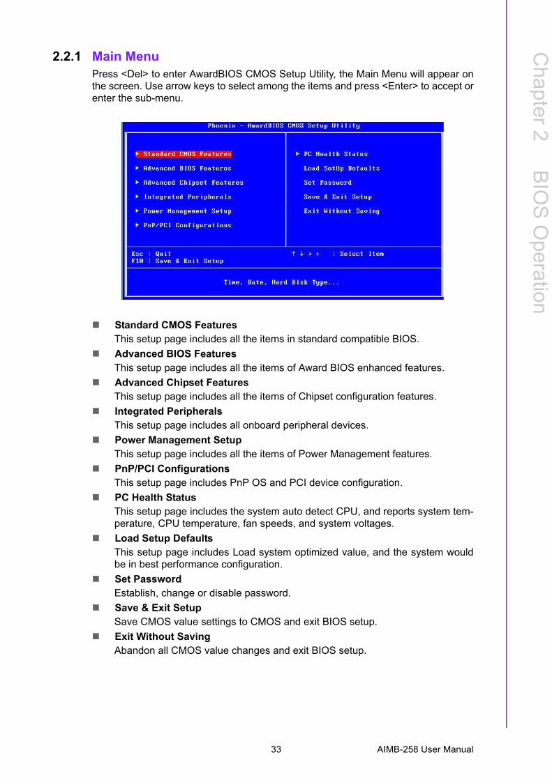
2.2.1 Main MenuPress <Del> to enter AwardBIOS CMOS Setup Utility, the Main Menu will appear onthe screen. Use arrow keys to select among the items and press <Enter> to accept orenter the sub-menu.
! Standard CMOS FeaturesThis setup page includes all the items in standard compatible BIOS.
! Advanced BIOS FeaturesThis setup page includes all the items of Award BIOS enhanced features.
! Advanced Chipset FeaturesThis setup page includes all the items of Chipset configuration features.
! Integrated PeripheralsThis setup page includes all onboard peripheral devices.
! Power Management SetupThis setup page includes all the items of Power Management features.
! PnP/PCI Configurations This setup page includes PnP OS and PCI device configuration.
! PC Health StatusThis setup page includes the system auto detect CPU, and reports system tem-perature, CPU temperature, fan speeds, and system voltages.
! Load Setup DefaultsThis setup page includes Load system optimized value, and the system wouldbe in best performance configuration.
! Set PasswordEstablish, change or disable password.
! Save & Exit SetupSave CMOS value settings to CMOS and exit BIOS setup.
! Exit Without SavingAbandon all CMOS value changes and exit BIOS setup.
33 AIMB-258 User Manual
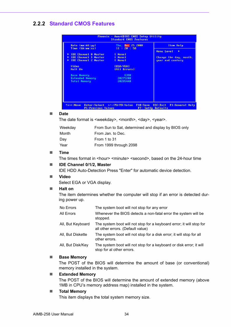
2.2.2 Standard CMOS Features
! DateThe date format is <weekday>, <month>, <day>, <year>.
! TimeThe times format in <hour> <minute> <second>, based on the 24-hour time
! IDE Channel 0/1/2, MasterIDE HDD Auto-Detection Press "Enter" for automatic device detection.
! VideoSelect EGA or VGA display.
! Halt onThe item determines whether the computer will stop if an error is detected dur-ing power up.
! Base MemoryThe POST of the BIOS will determine the amount of base (or conventional)memory installed in the system.
! Extended MemoryThe POST of the BIOS will determine the amount of extended memory (above1MB in CPU�s memory address map) installed in the system.
! Total MemoryThis item displays the total system memory size.
Weekday From Sun to Sat, determined and display by BIOS onlyMonth From Jan. to Dec.Day From 1 to 31 Year From 1999 through 2098
No Errors The system boot will not stop for any errorAll Errors Whenever the BIOS detects a non-fatal error the system will be
stopped.All, But Keyboard The system boot will not stop for a keyboard error; it will stop for
all other errors. (Default value)All, But Diskette The system boot will not stop for a disk error; it will stop for all
other errors.All, But Disk/Key The system boot will not stop for a keyboard or disk error; it will
stop for al other errors.
AIMB-258 User Manual 34
Chapter 2
BIO
S O
peration
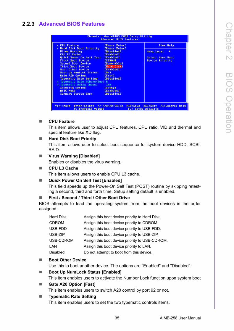
2.2.3 Advanced BIOS Features
! CPU FeatureThis item allows user to adjust CPU features, CPU ratio, VID and thermal andspecial feature like XD flag.
! Hard Disk Boot PriorityThis item allows user to select boot sequence for system device HDD, SCSI,RAID.
! Virus Warning [Disabled]Enables or disables the virus warning.
! CPU L3 CacheThis item allows users to enable CPU L3 cache.
! Quick Power On Self Test [Enabled]This field speeds up the Power-On Self Test (POST) routine by skipping retest-ing a second, third and forth time. Setup setting default is enabled.
! First / Second / Third / Other Boot DriveBIOS attempts to load the operating system from the boot devices in the orderassigned.
! Boot Other DeviceUse this to boot another device. The options are "Enabled" and "Disabled".
! Boot Up NumLock Status [Enabled]This item enables users to activate the Number Lock function upon system boot
! Gate A20 Option [Fast]This item enables users to switch A20 control by port 92 or not.
! Typematic Rate SettingThis item enables users to set the two typematic controls items.
Hard Disk Assign this boot device priority to Hard Disk.CDROM Assign this boot device priority to CDROM.USB-FDD Assign this boot device priority to USB-FDD.USB-ZIP Assign this boot device priority to USB-ZIP.USB-CDROM Assign this boot device priority to USB-CDROM.LAN Assign this boot device priority to LAN.Disabled Do not attempt to boot from this device.
35 AIMB-258 User Manual
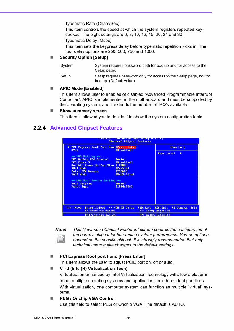
� Typematic Rate (Chars/Sec)This item controls the speed at which the system registers repeated key-strokes. The eight settings are 6, 8, 10, 12, 15, 20, 24 and 30.
� Typematic Delay (Msec)This item sets the keypress delay before typematic repetition kicks in. The four delay options are 250, 500, 750 and 1000.
! Security Option [Setup]
! APIC Mode [Enabled]This item allows user to enabled of disabled �Advanced Programmable InterruptController�. APIC is implemented in the motherboard and must be supported bythe operating system, and it extends the number of IRQ's available.
! Show summary screenThis item is allowed you to decide if to show the system configuration table.
2.2.4 Advanced Chipset Features
! PCI Express Root port Func [Press Enter]This item allows the user to adjust PCIE port on, off or auto.
! VT-d (Intel(R) Virtualization Tech)Virtualization enhanced by Intel Virtualization Technology will allow a platformto run multiple operating systems and applications in independent partitions.With virtualization, one computer system can function as multiple �virtual� sys-tems.
! PEG / Onchip VGA ControlUse this field to select PEG or Onchip VGA. The default is AUTO.
System System requires password both for bootup and for access to the Setup page.
Setup Setup requires password only for access to the Setup page, not for bootup. (Default value)
Note! This �Advanced Chipset Features� screen controls the configuration of the board�s chipset for fine-tuning system performance. Screen options depend on the specific chipset. It is strongly recommended that only technical users make changes to the default settings.
AIMB-258 User Manual 36
Chapter 2
BIO
S O
peration
! PEG Force x1Enabled or Disabled.
! On-Chip Frame Buffer SizeThe On-Chip Frame Buffer Size can be set to 1 MB or 8 MB. This memoryis shared with the system memory.
! DVMT ModeIntel's Dynamic Video Memory Technology (DVMT) allows the system to dynam-ically allocate memory resources according to the demands of the system at anypoint in time. The key idea in DVMT is to improve the efficiency of the memoryallocated to either system or graphics processor.
! Total GFX MemoryWhen "Enable" DVMT Mode, the graphics driver will allocate a fixed amount ofmemory as dedicated graphics memory, as well as allow more system memoryto be dynamically allocated between the graphics processorand the operating system.
! PAVP ModeThis setting enables/disables the Protected Audio/Video Path (PAVP) mode.
! Boot DisplayUse the field to select the type of device you want to use as the display(s) ofthe system.
! Panel typeSelect panel resolution.
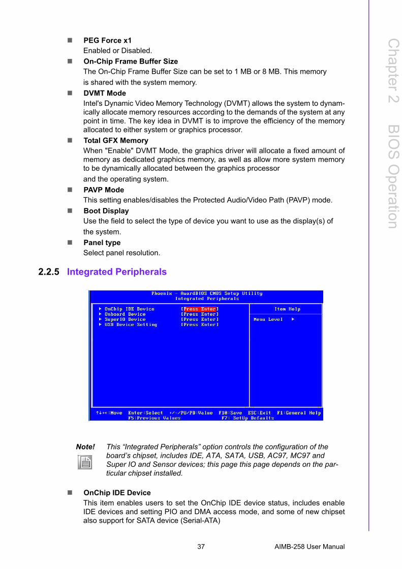
2.2.5 Integrated Peripherals
! OnChip IDE Device This item enables users to set the OnChip IDE device status, includes enableIDE devices and setting PIO and DMA access mode, and some of new chipsetalso support for SATA device (Serial-ATA)
Note! This �Integrated Peripherals� option controls the configuration of the board�s chipset, includes IDE, ATA, SATA, USB, AC97, MC97 and Super IO and Sensor devices; this page this page depends on the par-ticular chipset installed.
37 AIMB-258 User Manual
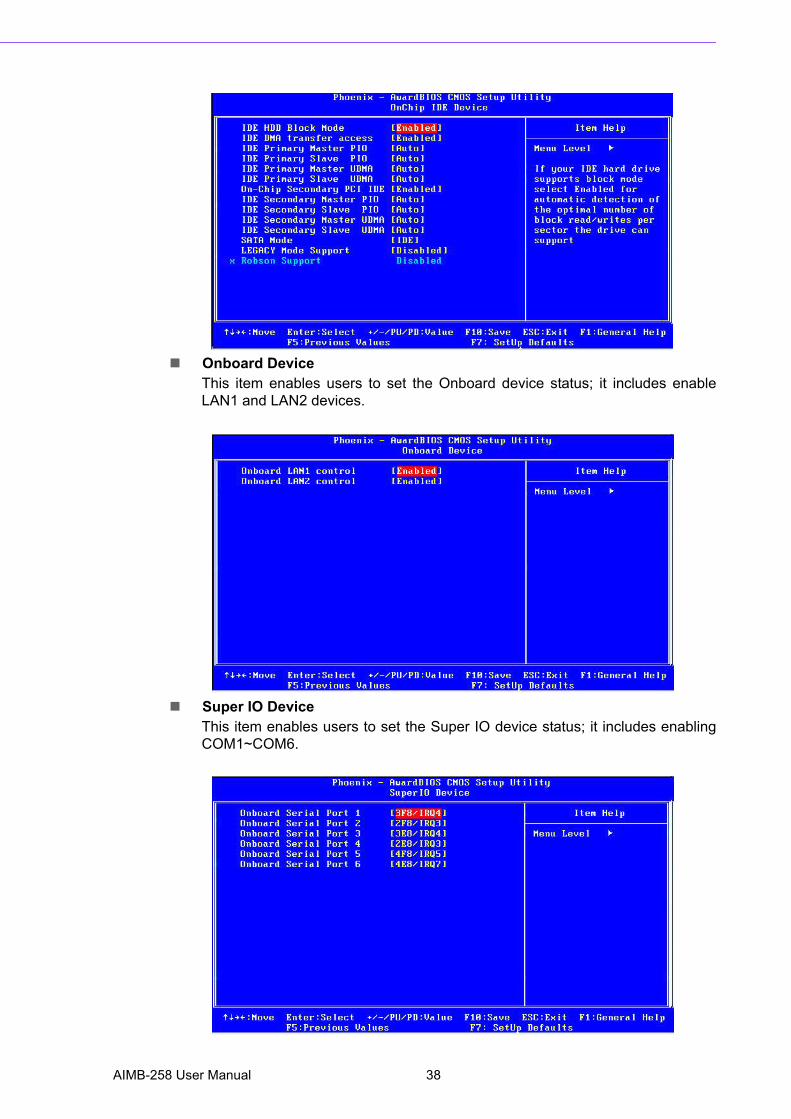
! Onboard Device This item enables users to set the Onboard device status; it includes enableLAN1 and LAN2 devices.
! Super IO Device This item enables users to set the Super IO device status; it includes enablingCOM1~COM6.
AIMB-258 User Manual 38
Chapter 2
BIO
S O
peration
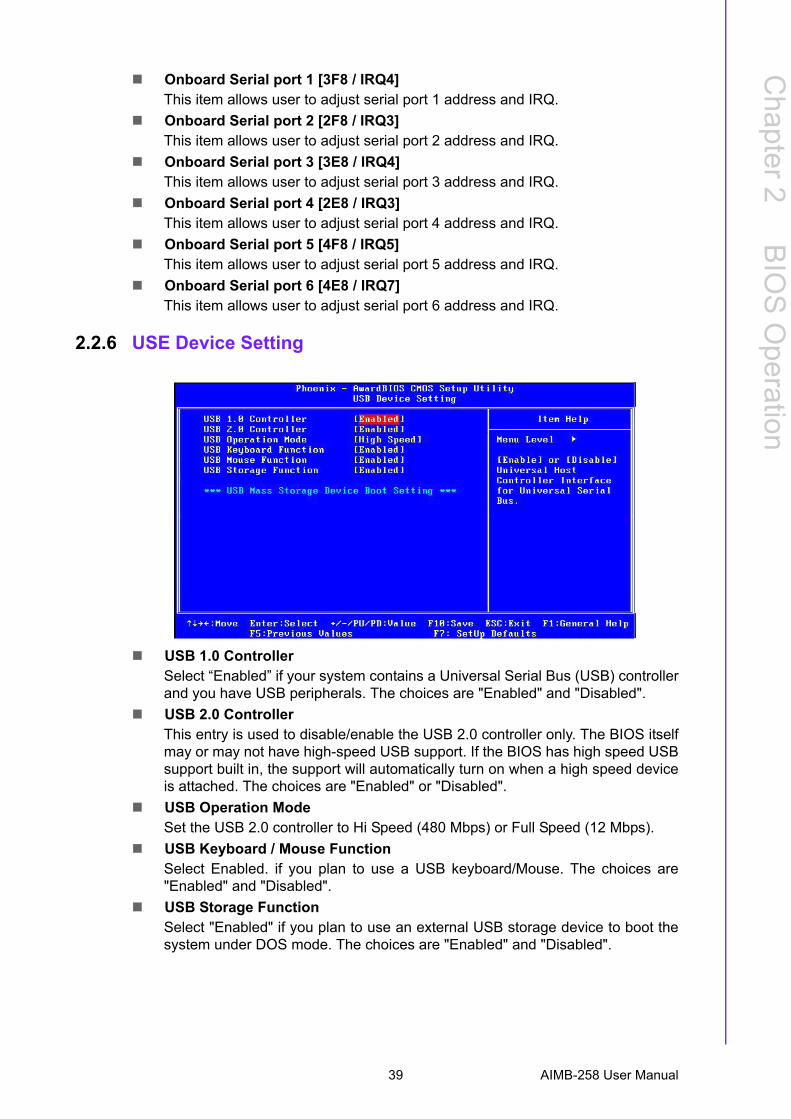
! Onboard Serial port 1 [3F8 / IRQ4]This item allows user to adjust serial port 1 address and IRQ.
! Onboard Serial port 2 [2F8 / IRQ3]This item allows user to adjust serial port 2 address and IRQ.
! Onboard Serial port 3 [3E8 / IRQ4]This item allows user to adjust serial port 3 address and IRQ.
! Onboard Serial port 4 [2E8 / IRQ3]This item allows user to adjust serial port 4 address and IRQ.
! Onboard Serial port 5 [4F8 / IRQ5]This item allows user to adjust serial port 5 address and IRQ.
! Onboard Serial port 6 [4E8 / IRQ7]This item allows user to adjust serial port 6 address and IRQ.
2.2.6 USE Device Setting
! USB 1.0 ControllerSelect �Enabled� if your system contains a Universal Serial Bus (USB) controllerand you have USB peripherals. The choices are "Enabled" and "Disabled".
! USB 2.0 ControllerThis entry is used to disable/enable the USB 2.0 controller only. The BIOS itselfmay or may not have high-speed USB support. If the BIOS has high speed USBsupport built in, the support will automatically turn on when a high speed deviceis attached. The choices are "Enabled" or "Disabled".
! USB Operation ModeSet the USB 2.0 controller to Hi Speed (480 Mbps) or Full Speed (12 Mbps).
! USB Keyboard / Mouse FunctionSelect Enabled. if you plan to use a USB keyboard/Mouse. The choices are"Enabled" and "Disabled".
! USB Storage FunctionSelect "Enabled" if you plan to use an external USB storage device to boot thesystem under DOS mode. The choices are "Enabled" and "Disabled".
39 AIMB-258 User Manual
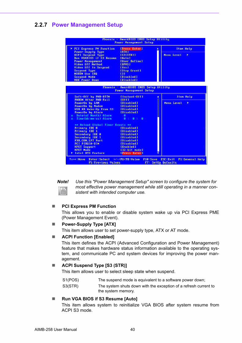
2.2.7 Power Management Setup
! PCI Express PM FunctionThis allows you to enable or disable system wake up via PCI Express PME(Power Management Event).
! Power-Supply Type [ATX]This item allows user to set power-supply type, ATX or AT mode.
! ACPI Function [Enabled]This item defines the ACPI (Advanced Configuration and Power Management)feature that makes hardware status information available to the operating sys-tem, and communicate PC and system devices for improving the power man-agement.
! ACPI Suspend Type [S3 (STR)]This item allows user to select sleep state when suspend.
! Run VGA BIOS if S3 Resume [Auto]This item allows system to reinitialize VGA BIOS after system resume fromACPI S3 mode.
Note! Use this "Power Management Setup" screen to configure the system for most effective power management while still operating in a manner con-sistent with intended computer use.
S1(POS) The suspend mode is equivalent to a software power down;S3(STR) The system shuts down with the exception of a refresh current to
the system memory.
AIMB-258 User Manual 40
Chapter 2
BIO
S O
peration
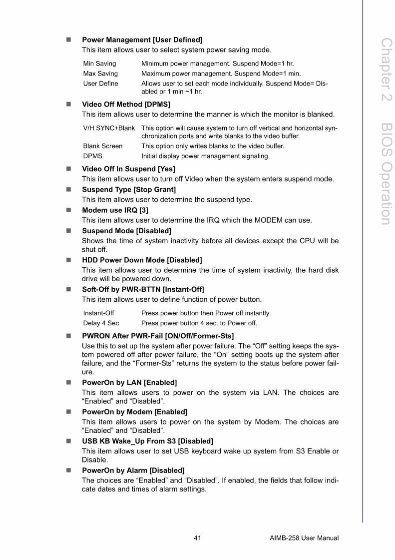
! Power Management [User Defined]This item allows user to select system power saving mode.
! Video Off Method [DPMS]This item allows user to determine the manner is which the monitor is blanked.
! Video Off In Suspend [Yes]This item allows user to turn off Video when the system enters suspend mode.
! Suspend Type [Stop Grant]This item allows user to determine the suspend type.
! Modem use IRQ [3]This item allows user to determine the IRQ which the MODEM can use.
! Suspend Mode [Disabled]Shows the time of system inactivity before all devices except the CPU will beshut off.
! HDD Power Down Mode [Disabled]This item allows user to determine the time of system inactivity, the hard diskdrive will be powered down.
! Soft-Off by PWR-BTTN [Instant-Off]This item allows user to define function of power button.
! PWRON After PWR-Fail [ON/Off/Former-Sts]Use this to set up the system after power failure. The �Off� setting keeps the sys-tem powered off after power failure, the �On� setting boots up the system afterfailure, and the �Former-Sts� returns the system to the status before power fail-ure.
! PowerOn by LAN [Enabled]This item allows users to power on the system via LAN. The choices are�Enabled� and �Disabled�.
! PowerOn by Modem [Enabled]This item allows users to power on the system by Modem. The choices are�Enabled� and �Disabled�.
! USB KB Wake_Up From S3 [Disabled]This item allows user to set USB keyboard wake up system from S3 Enable orDisable.
! PowerOn by Alarm [Disabled]The choices are �Enabled� and �Disabled�. If enabled, the fields that follow indi-cate dates and times of alarm settings.
Min Saving Minimum power management. Suspend Mode=1 hr.Max Saving Maximum power management. Suspend Mode=1 min.User Define Allows user to set each mode individually. Suspend Mode= Dis-
abled or 1 min ~1 hr.
V/H SYNC+Blank This option will cause system to turn off vertical and horizontal syn-chronization ports and write blanks to the video buffer.
Blank Screen This option only writes blanks to the video buffer.DPMS Initial display power management signaling.
Instant-Off Press power button then Power off instantly.Delay 4 Sec Press power button 4 sec. to Power off.
41 AIMB-258 User Manual
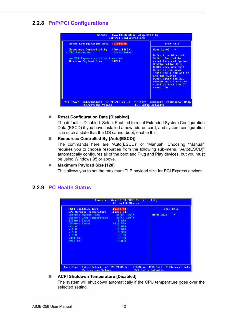
2.2.8 PnP/PCI Configurations
! Reset Configuration Data [Disabled]The default is Disabled. Select Enabled to reset Extended System ConfigurationData (ESCD) if you have installed a new add-on card, and system configurationis in such a state that the OS cannot boot, enable this.
! Resources Controlled By [Auto(ESCD)]The commands here are �Auto(ESCD)� or �Manual�. Choosing �Manual�requires you to choose resources from the following sub-menu. �Auto(ESCD)�automatically configures all of the boot and Plug and Play devices, but you mustbe using Windows 95 or above.
! Maximum Payload Size [128]This allows you to set the maximum TLP payload size for PCI Express devices.
2.2.9 PC Health Status
! ACPI Shutdown Temperature [Disabled]The system will shut down automatically if the CPU temperature goes over theselected setting.
AIMB-258 User Manual 42
Chapter 2
BIO
S O
peration
! CPU Warning TemperatureThe system will give an automatic warning if the CPU temperature goes over theselected setting.
! Current System TemperatureThis shows you the current temperature of system.
! Current CPU TemperatureThis shows the current CPU temperature.
! VCORE and Other VoltagesThis shows the voltage of VCORE, +12 V, +3 V, +5 V, VBAT (V), and 5 VSB (V).
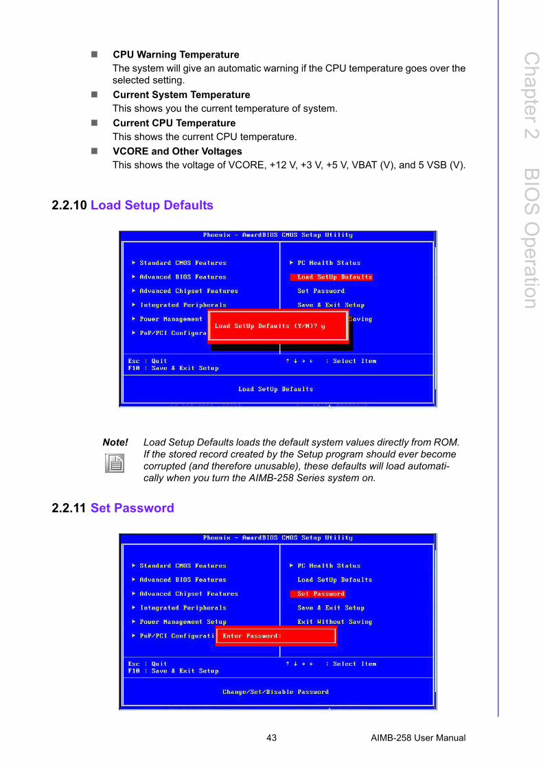
2.2.10 Load Setup Defaults
2.2.11 Set Password
Note! Load Setup Defaults loads the default system values directly from ROM. If the stored record created by the Setup program should ever become corrupted (and therefore unusable), these defaults will load automati-cally when you turn the AIMB-258 Series system on.
43 AIMB-258 User Manual
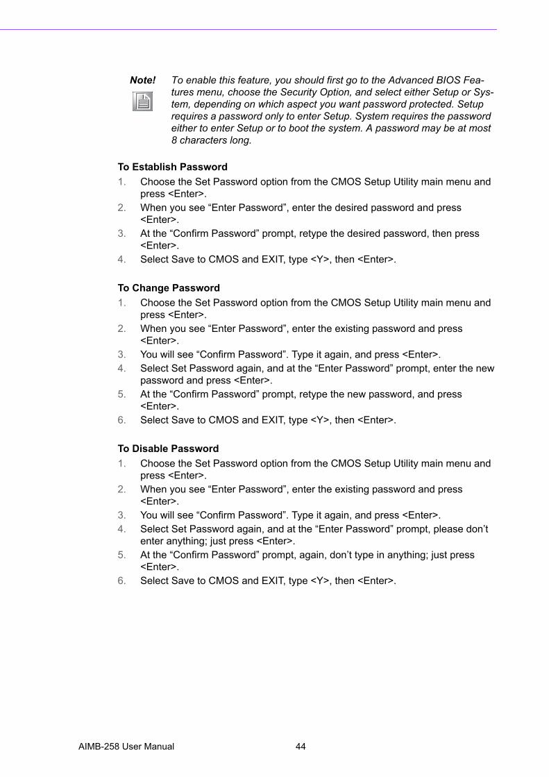
To Establish Password1. Choose the Set Password option from the CMOS Setup Utility main menu and
press <Enter>.2. When you see �Enter Password�, enter the desired password and press
<Enter>.3. At the �Confirm Password� prompt, retype the desired password, then press
<Enter>.4. Select Save to CMOS and EXIT, type <Y>, then <Enter>.
To Change Password1. Choose the Set Password option from the CMOS Setup Utility main menu and
press <Enter>.2. When you see �Enter Password�, enter the existing password and press
<Enter>.3. You will see �Confirm Password�. Type it again, and press <Enter>.4. Select Set Password again, and at the �Enter Password� prompt, enter the new
password and press <Enter>.5. At the �Confirm Password� prompt, retype the new password, and press
<Enter>.6. Select Save to CMOS and EXIT, type <Y>, then <Enter>.
To Disable Password1. Choose the Set Password option from the CMOS Setup Utility main menu and
press <Enter>.2. When you see �Enter Password�, enter the existing password and press
<Enter>.3. You will see �Confirm Password�. Type it again, and press <Enter>.4. Select Set Password again, and at the �Enter Password� prompt, please don�t
enter anything; just press <Enter>.5. At the �Confirm Password� prompt, again, don�t type in anything; just press
<Enter>.6. Select Save to CMOS and EXIT, type <Y>, then <Enter>.
Note! To enable this feature, you should first go to the Advanced BIOS Fea-tures menu, choose the Security Option, and select either Setup or Sys-tem, depending on which aspect you want password protected. Setup requires a password only to enter Setup. System requires the password either to enter Setup or to boot the system. A password may be at most 8 characters long.
AIMB-258 User Manual 44
Chapter 3
3 Chipset Software Install Utility
3.1 Before you BeginTo facilitate the installation of the enhanced display device drivers and utility soft-ware, you should read the instructions in this chapter carefully before you begin. Thedevice drivers for the AIMB-258 board are located on the software installation CD.The auto-run function of the driver CD will guide you to the utilities and device driversrequired for a Windows system. The Intel® Chipset Software Installation Utility is notrequired on any systems running Windows NT 4.0. Updates are provided via ServicePacks from Microsoft®.
Before you begin, it is important to note that most display drivers need to have therelevant software application already installed in the system prior to installing theenhanced display drivers. In addition, many of the installation procedures assumethat you are familiar with both the relevant software applications and operating sys-tem commands. Review the relevant operating system commands and the pertinentsections of your application software's user's manual before performing the installa-tion.
3.2 IntroductionThe Intel® Chipset Software Installation utility installs to the target system the Win-dows INF files that outline to the operating system how the chipset components willbe configured. This is needed for the proper functioning of the following features:! Core PCI and ISA PnP services! IDE Ultra ATA 100/66/33 and Serial ATA interface support! USB 1.1/2.0 support! Identification of Intel® chipset components in the Device Manager! Integrates superior video features. These include filtered sealing of 720 pixel
DVD content, and MPEG-2 motion compensation for software DVD
Note! The files on the software installation CD are compressed. Do not attempt to install the drivers by copying the files manually. You must use the supplied SETUP program to install the drivers
Note! This utility is used for the following versions of Windows system, and it has to be installed before installing all the other drivers:Windows XPWindows Vista
AIMB-258 User Manual 46
Chapter 3
ChipsetS
oftware
InstallUtility
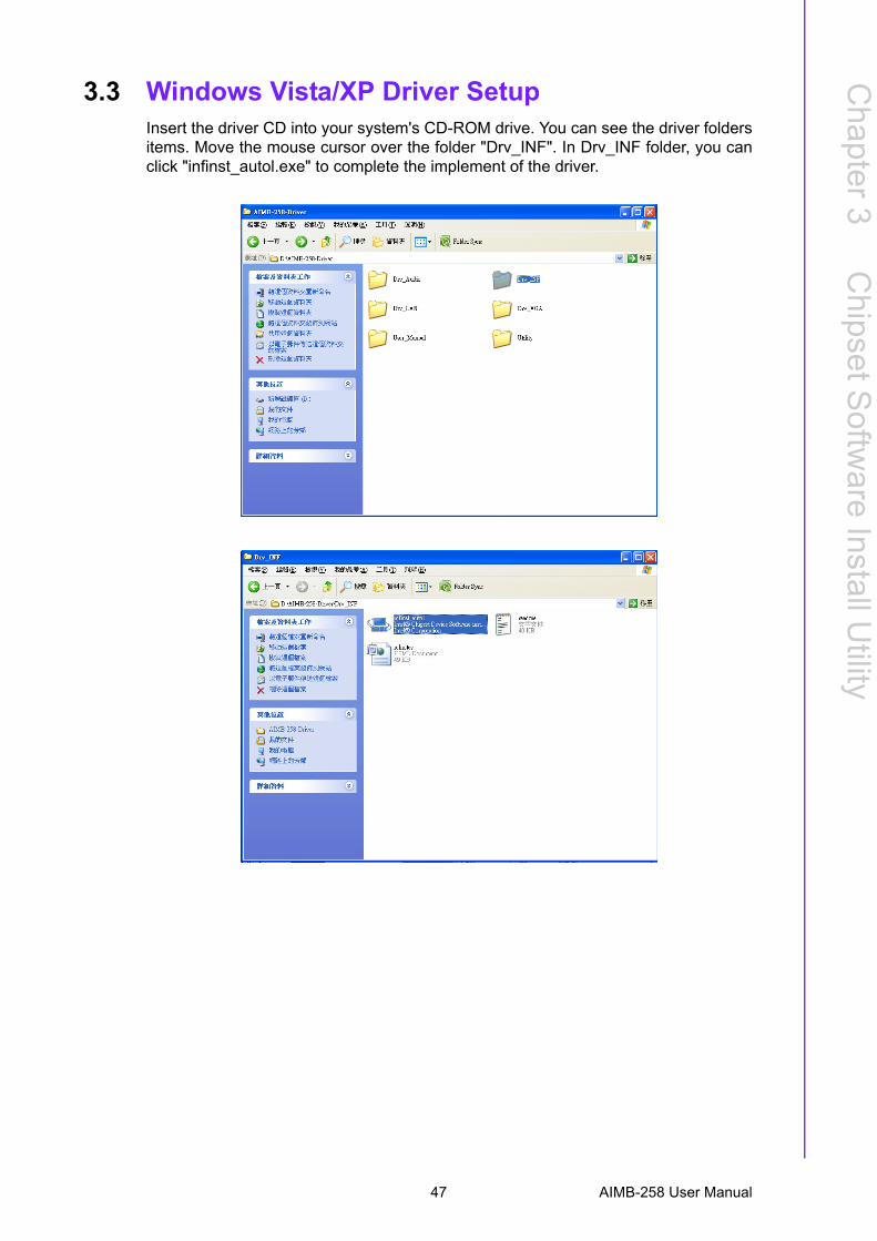
3.3 Windows Vista/XP Driver SetupInsert the driver CD into your system's CD-ROM drive. You can see the driver foldersitems. Move the mouse cursor over the folder "Drv_INF". In Drv_INF folder, you canclick "infinst_autol.exe" to complete the implement of the driver.
47 AIMB-258 User Manual

AIMB-258 User Manual 48

Chapter 4
4 VGA Setup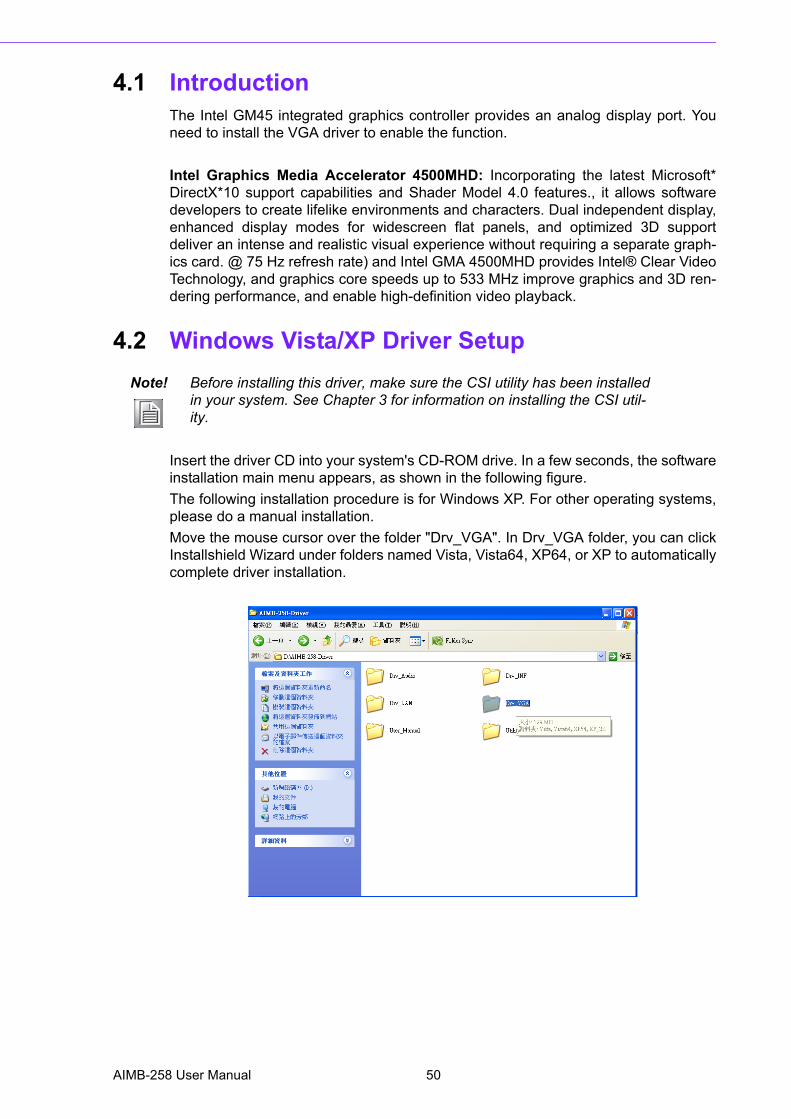
4.1 IntroductionThe Intel GM45 integrated graphics controller provides an analog display port. Youneed to install the VGA driver to enable the function.
Intel Graphics Media Accelerator 4500MHD: Incorporating the latest Microsoft*DirectX*10 support capabilities and Shader Model 4.0 features., it allows softwaredevelopers to create lifelike environments and characters. Dual independent display,enhanced display modes for widescreen flat panels, and optimized 3D supportdeliver an intense and realistic visual experience without requiring a separate graph-ics card. @ 75 Hz refresh rate) and Intel GMA 4500MHD provides Intel® Clear VideoTechnology, and graphics core speeds up to 533 MHz improve graphics and 3D ren-dering performance, and enable high-definition video playback.
4.2 Windows Vista/XP Driver Setup
Insert the driver CD into your system's CD-ROM drive. In a few seconds, the softwareinstallation main menu appears, as shown in the following figure.The following installation procedure is for Windows XP. For other operating systems,please do a manual installation.Move the mouse cursor over the folder "Drv_VGA". In Drv_VGA folder, you can clickInstallshield Wizard under folders named Vista, Vista64, XP64, or XP to automaticallycomplete driver installation.
Note! Before installing this driver, make sure the CSI utility has been installed in your system. See Chapter 3 for information on installing the CSI util-ity.
AIMB-258 User Manual 50
Chapter 5
5 LAN Configuration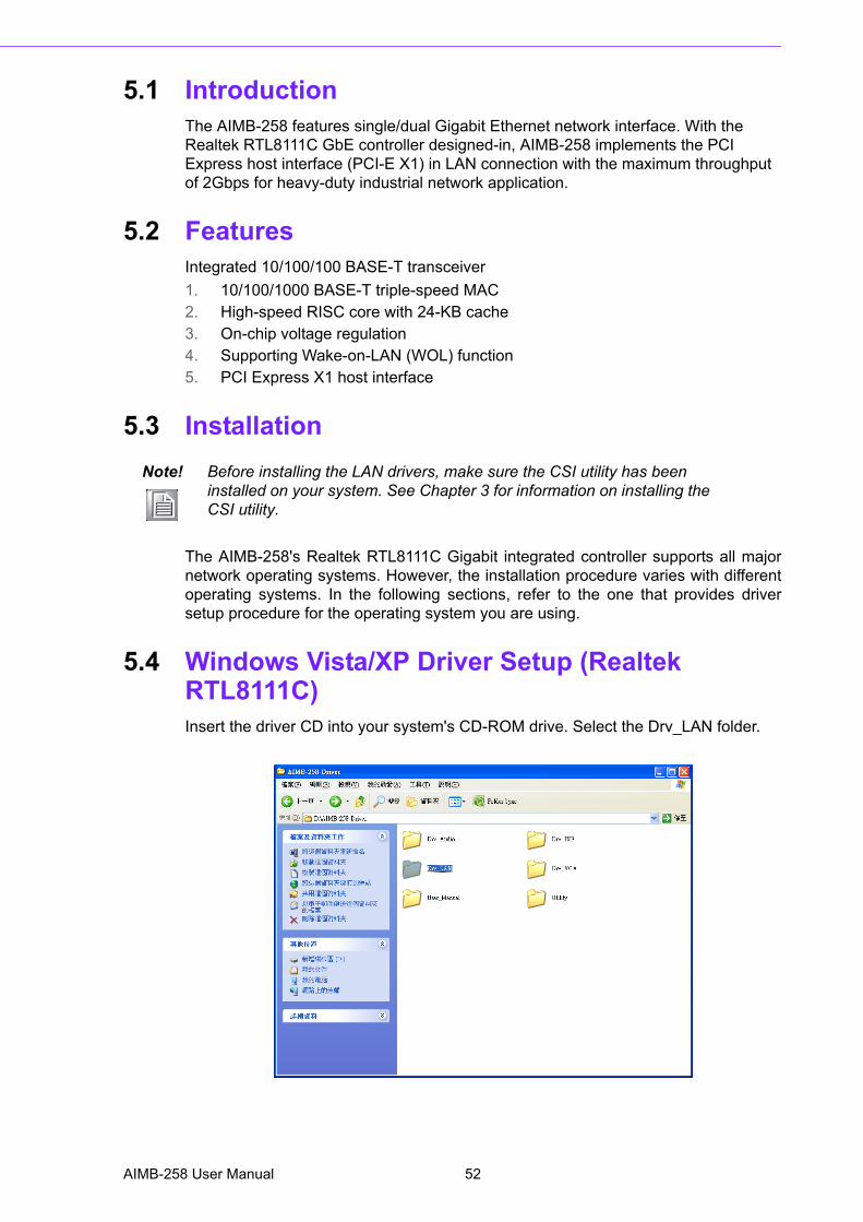
5.1 IntroductionThe AIMB-258 features single/dual Gigabit Ethernet network interface. With the Realtek RTL8111C GbE controller designed-in, AIMB-258 implements the PCI Express host interface (PCI-E X1) in LAN connection with the maximum throughput of 2Gbps for heavy-duty industrial network application.
5.2 FeaturesIntegrated 10/100/100 BASE-T transceiver1. 10/100/1000 BASE-T triple-speed MAC2. High-speed RISC core with 24-KB cache3. On-chip voltage regulation4. Supporting Wake-on-LAN (WOL) function5. PCI Express X1 host interface
5.3 Installation
The AIMB-258's Realtek RTL8111C Gigabit integrated controller supports all majornetwork operating systems. However, the installation procedure varies with differentoperating systems. In the following sections, refer to the one that provides driversetup procedure for the operating system you are using.
5.4 Windows Vista/XP Driver Setup (Realtek RTL8111C)Insert the driver CD into your system's CD-ROM drive. Select the Drv_LAN folder.
Note! Before installing the LAN drivers, make sure the CSI utility has been installed on your system. See Chapter 3 for information on installing the CSI utility.
AIMB-258 User Manual 52
Chapter 5
LAN
Configuration
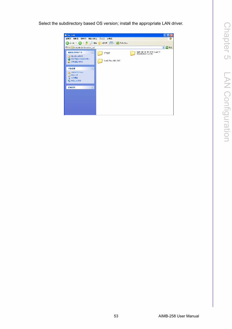
Select the subdirectory based OS version; install the appropriate LAN driver.
53 AIMB-258 User Manual

AIMB-258 User Manual 54

Appendix A
A Programming the Watchdog Timer
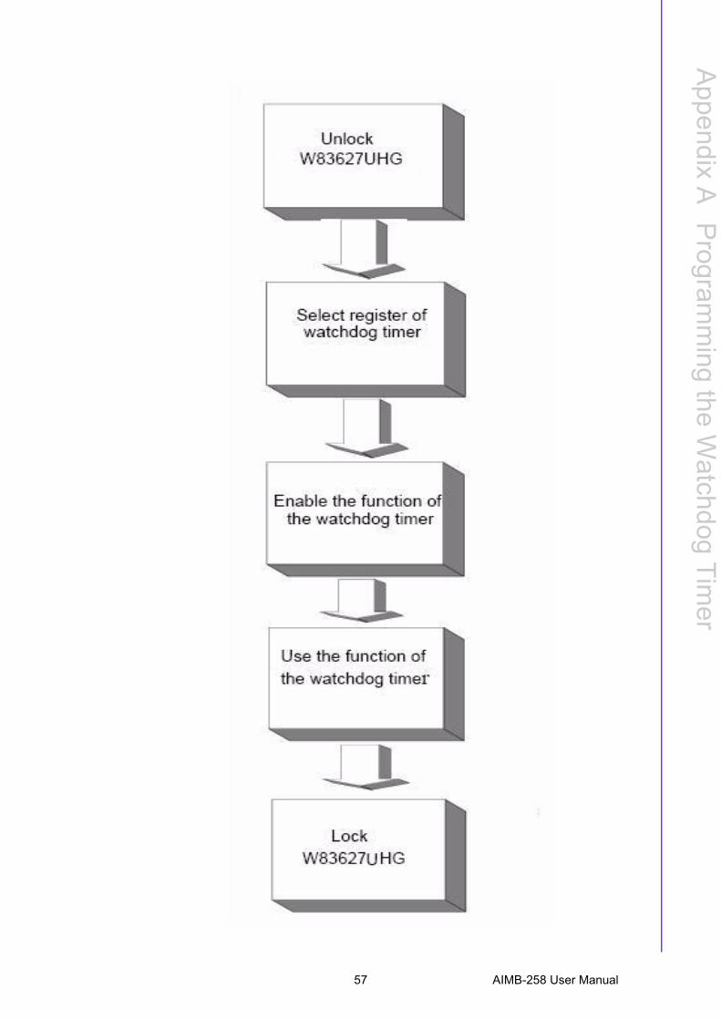
A.1 Programming the Watchdog TimerThe AIMB-258's watchdog timer can be used to monitor system software operationand take corrective action if the software fails to function after the programmedperiod. This section describes the operation of the watchdog timer and how to pro-gram it.
A.1.1 Watchdog timer overviewThe watchdog timer is built into the super I/O controller W83627UHG. It provides thefollowing functions for user programming:! Can be enabled and disabled by user's program.! Timer can be set from 1 to 255 seconds or 1 to 255 minutes.! Generates an interrupt or resets signal if the software fails to reset the timer
after time-out.
A.1.2 Programming the Watchdog TimerThe I/O port address of the watchdog timer is 2E(hex) and 2F(hex). 2E (hex) is the address port. 2F(hex) is the data port.You must first assign the address of register by writing address value into addressport 2E(hex), then write/read data to/from the assigned register through data port 2F(hex).
AIMB-258 User Manual 56
Appendix A
Program
ming
theW
atchdogTim
er
57 AIMB-258 User Manual
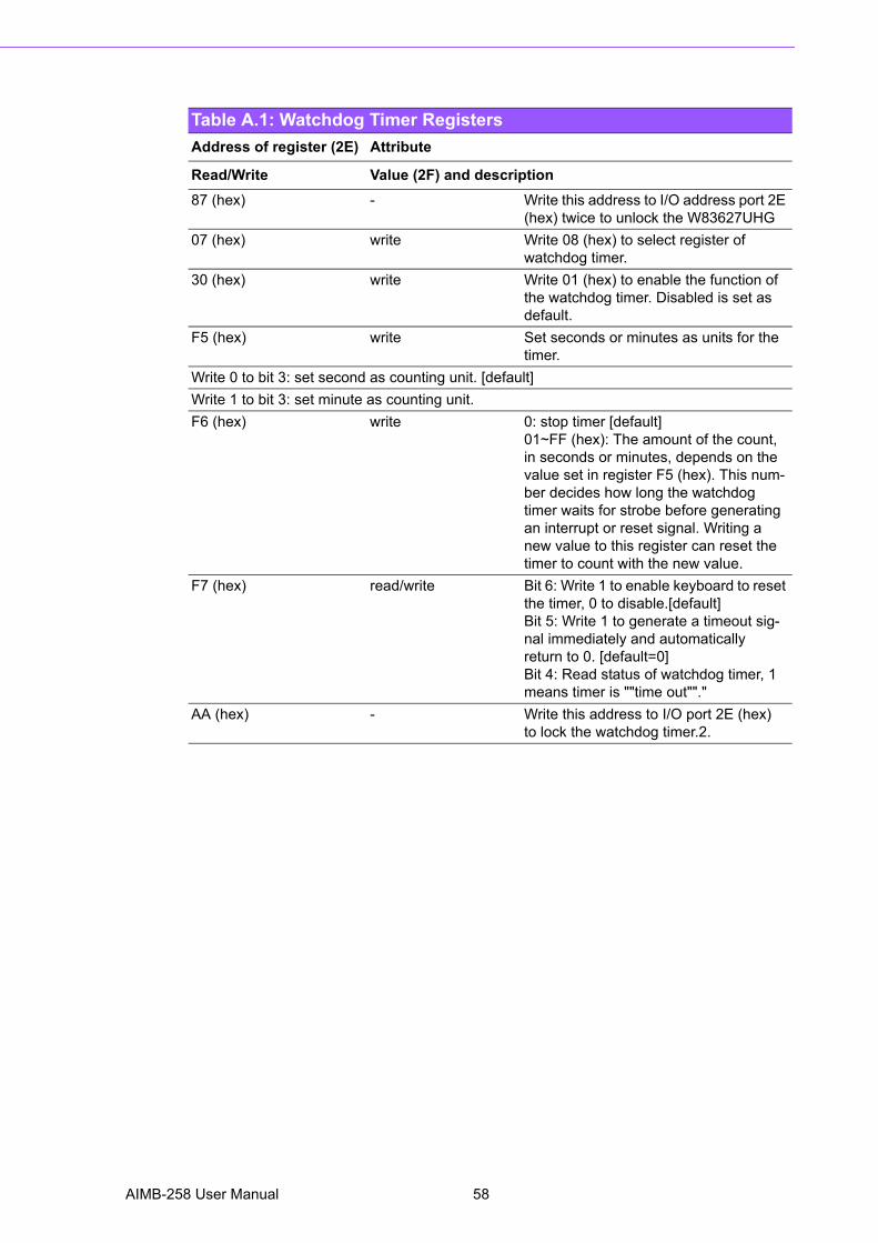
Table A.1: Watchdog Timer RegistersAddress of register (2E) Attribute
Read/Write Value (2F) and description87 (hex) - Write this address to I/O address port 2E
(hex) twice to unlock the W83627UHG07 (hex) write Write 08 (hex) to select register of
watchdog timer.30 (hex) write Write 01 (hex) to enable the function of
the watchdog timer. Disabled is set as default.
F5 (hex) write Set seconds or minutes as units for the timer.
Write 0 to bit 3: set second as counting unit. [default]Write 1 to bit 3: set minute as counting unit.F6 (hex) write 0: stop timer [default]
01~FF (hex): The amount of the count, in seconds or minutes, depends on the value set in register F5 (hex). This num-ber decides how long the watchdog timer waits for strobe before generating an interrupt or reset signal. Writing a new value to this register can reset the timer to count with the new value.
F7 (hex) read/write Bit 6: Write 1 to enable keyboard to reset the timer, 0 to disable.[default]Bit 5: Write 1 to generate a timeout sig-nal immediately and automaticallyreturn to 0. [default=0]Bit 4: Read status of watchdog timer, 1 means timer is ""time out""."
AA (hex) - Write this address to I/O port 2E (hex)to lock the watchdog timer.2.
AIMB-258 User Manual 58
Appendix A
Program
ming
theW
atchdogTim
er
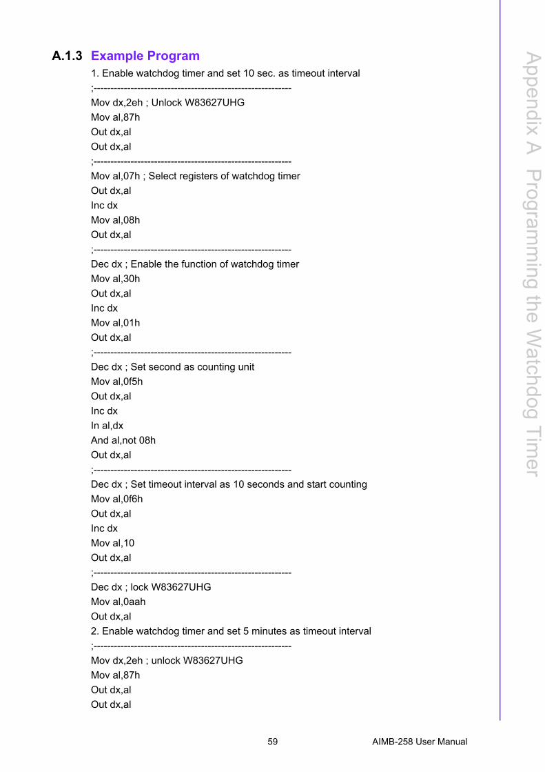
A.1.3 Example Program1. Enable watchdog timer and set 10 sec. as timeout interval;-----------------------------------------------------------Mov dx,2eh ; Unlock W83627UHGMov al,87hOut dx,alOut dx,al;-----------------------------------------------------------Mov al,07h ; Select registers of watchdog timerOut dx,alInc dxMov al,08hOut dx,al;-----------------------------------------------------------Dec dx ; Enable the function of watchdog timerMov al,30hOut dx,alInc dxMov al,01hOut dx,al;-----------------------------------------------------------Dec dx ; Set second as counting unitMov al,0f5hOut dx,alInc dxIn al,dxAnd al,not 08hOut dx,al;-----------------------------------------------------------Dec dx ; Set timeout interval as 10 seconds and start countingMov al,0f6hOut dx,alInc dxMov al,10Out dx,al;-----------------------------------------------------------Dec dx ; lock W83627UHGMov al,0aahOut dx,al2. Enable watchdog timer and set 5 minutes as timeout interval;-----------------------------------------------------------Mov dx,2eh ; unlock W83627UHGMov al,87hOut dx,alOut dx,al
59 AIMB-258 User Manual
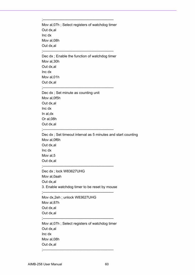
;-----------------------------------------------------------Mov al,07h ; Select registers of watchdog timerOut dx,alInc dxMov al,08hOut dx,al;-----------------------------------------------------------Dec dx ; Enable the function of watchdog timerMov al,30hOut dx,alInc dxMov al,01hOut dx,al;-----------------------------------------------------------Dec dx ; Set minute as counting unitMov al,0f5hOut dx,alInc dxIn al,dxOr al,08hOut dx,al;-----------------------------------------------------------Dec dx ; Set timeout interval as 5 minutes and start countingMov al,0f6hOut dx,alInc dxMov al,5Out dx,al;-----------------------------------------------------------Dec dx ; lock W83627UHGMov al,0aahOut dx,al3. Enable watchdog timer to be reset by mouse;-----------------------------------------------------------Mov dx,2eh ; unlock W83627UHGMov al,87hOut dx,alOut dx,al;-----------------------------------------------------------Mov al,07h ; Select registers of watchdog timerOut dx,alInc dxMov al,08hOut dx,al;-----------------------------------------------------------
AIMB-258 User Manual 60

Appendix A
Program
ming
theW
atchdogTim
er
Dec dx ; Enable the function of watchdog timerMov al,30hOut dx,alInc dxMov al,01hOut dx,al;-----------------------------------------------------------Dec dx ; Enable watchdog timer to be reset by mouseMov al,0f7hOut dx,alInc dxIn al,dxOr al,80hOut dx,al;-----------------------------------------------------------Dec dx ; lock W83627UHGMov al,0aahOut dx,al4. Enable watchdog timer to be reset by keyboard;-----------------------------------------------------------Mov dx,2eh ; unlock W83627UHGMov al,87hOut dx,alOut dx,al;-----------------------------------------------------------Mov al,07h ; Select registers of watchdog timerOut dx,alInc dxMov al,08hOut dx,al;-----------------------------------------------------------Dec dx ; Enable the function of watchdog timerMov al,30hOut dx,alInc dxMov al,01hOut dx,al;-----------------------------------------------------------Dec dx ; Enable watchdog timer to be strobed reset by keyboardMov al,0f7hOut dx,alInc dxIn al,dxOr al,40hOut dx,al
61 AIMB-258 User Manual
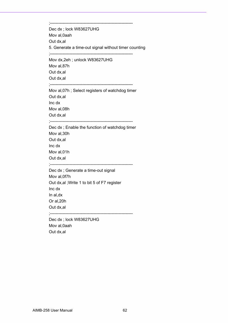
;-----------------------------------------------------------Dec dx ; lock W83627UHGMov al,0aahOut dx,al5. Generate a time-out signal without timer counting;-----------------------------------------------------------Mov dx,2eh ; unlock W83627UHGMov al,87hOut dx,alOut dx,al;-----------------------------------------------------------Mov al,07h ; Select registers of watchdog timerOut dx,alInc dxMov al,08hOut dx,al;-----------------------------------------------------------Dec dx ; Enable the function of watchdog timerMov al,30hOut dx,alInc dxMov al,01hOut dx,al;-----------------------------------------------------------Dec dx ; Generate a time-out signalMov al,0f7hOut dx,al ;Write 1 to bit 5 of F7 registerInc dxIn al,dxOr al,20hOut dx,al;-----------------------------------------------------------Dec dx ; lock W83627UHGMov al,0aahOut dx,al
AIMB-258 User Manual 62

Appendix B
B Pin Assignments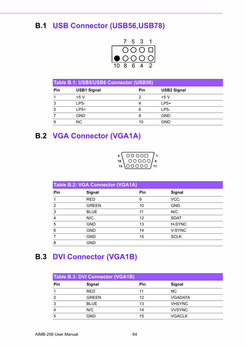
B.1 USB Connector (USB56,USB78)
B.2 VGA Connector (VGA1A)
B.3 DVI Connector (VGA1B)
Table B.1: USB5/USB6 Connector (USB56)Pin USB1 Signal Pin USB2 Signal1 +5 V 2 +5 V3 LP5- 4 LP5+5 LP5+ 6 LP5-7 GND 8 GND9 NC 10 GND
7 5 3 1
10 8 6 4 2
Table B.2: VGA Connector (VGA1A)Pin Signal Pin Signal1 RED 9 VCC2 GREEN 10 GND3 BLUE 11 N/C4 N/C 12 SDAT5 GND 13 H-SYNC6 GND 14 V-SYNC7 GND 15 SCLK8 GND
5
15
1
1110 6
Table B.3: DVI Connector (VGA1B)Pin Signal Pin Signal1 RED 11 NC2 GREEN 12 VGADATA3 BLUE 13 VHSYNC4 N/C 14 VVSYNC5 GND 15 VGACLK
AIMB-258 User Manual 64
Appendix B
Pin A
ssignments
B.4 RS-232 Serial Port (COM1~COM2)
6 GND 16 GND7 GND 17 GND8 GND9 +5V_VGA10 GND
Table B.3: DVI Connector (VGA1B)
Table B.4: RS-232 Serial Port (COM1~COM2)Pin Signal1 DCD/TX_422N/TX_485N2 RXD/TX_422P/TX_485P3 TXD/RX_422P4 DTR/RX_422N5 GND6 DSR7 RTS8 CTS9 RRI
1
6
65 AIMB-258 User Manual
B.5 RS-232 Serial Port (COM3 ~ COM6)
Table B.5: RS-232 Serial Port (COM23)Pin Signal Pin Signal1 COM3_#DCD 2 COM3_#DSR3 COM3_SIN 4 COM3_#RTS5 COM3_SOUT 6 COM3_#CTS7 COM3_#DTR 8 COM3_#RI9 GND 10 GND11 COM4_#DCD 12 COM4_#DSR13 COM4_SIN 14 COM4_#RTS15 COM4_SOUT 16 COM4_#CTS17 COM4_#DTR 18 COM4_#RI19 GND 20 GND21 COM5_#DCD 22 COM5_#DSR23 COM5_SIN 24 COM5_#RTS25 COM5_SOUT 26 COM5_#CTS27 COM5_#DTR 28 COM5_#RI29 GND 30 GND31 COM6_#DCD 32 COM6_#DSR33 COM6_SIN 34 COM6_#RTS35 COM6_SOUT 36 COM6_#CTS37 COM6_#DTR 38 COM6_#RI39 GND 40 GND
AIMB-258 User Manual 66
Appendix B
Pin A
ssignments
B.6 PS/2 Keyboard/ Mouse Connector (KBMS1)
B.7 CPU Fan Power Connector (CPUFAN1)
Table B.6: PS/2 Keyboard/ Mouse Connector (KBMS1)Pin Signal Pin Signal1 KB DATA 2 NC7 MS DATA 6 NC3 GND 8 NC4 VCC 9 GND5 KB CLOCK 10 VCC11 MS CLOCK 12 NC
12 11
10 9
8 7
5
3
12
4
6
Table B.7: CPU Fan Power Connector (CPUFAN1)Pin Signal1 GND2 +12 V3 DEC
1
2
3
67 AIMB-258 User Manual
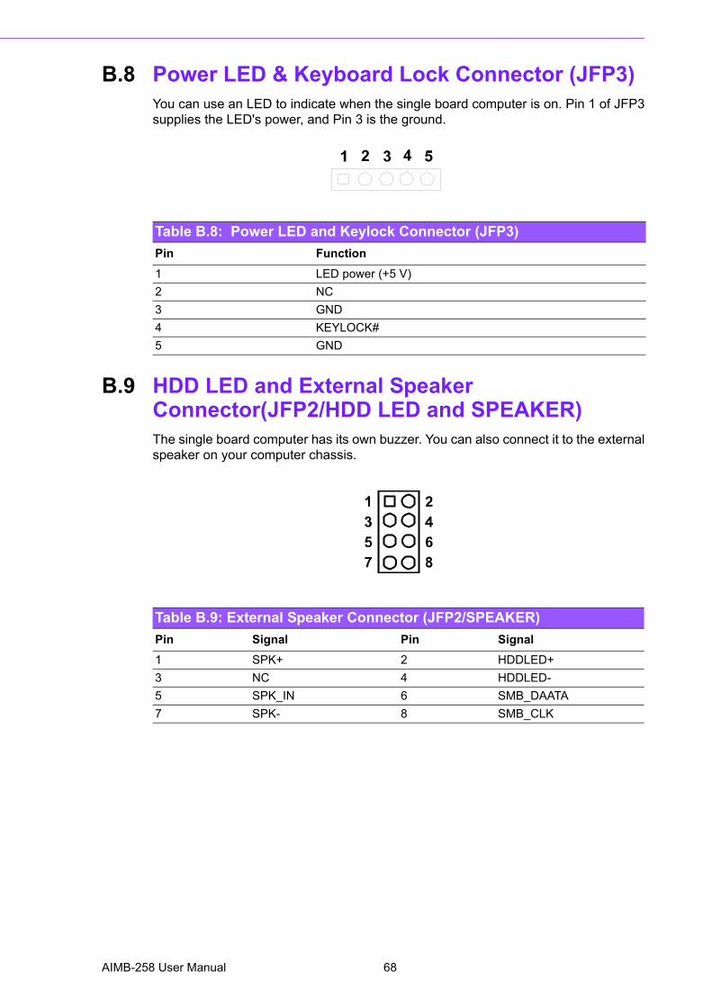
B.8 Power LED & Keyboard Lock Connector (JFP3)You can use an LED to indicate when the single board computer is on. Pin 1 of JFP3supplies the LED's power, and Pin 3 is the ground.
B.9 HDD LED and External Speaker Connector(JFP2/HDD LED and SPEAKER)The single board computer has its own buzzer. You can also connect it to the externalspeaker on your computer chassis.
Table B.8: Power LED and Keylock Connector (JFP3)Pin Function1 LED power (+5 V)2 NC3 GND4 KEYLOCK#5 GND
Table B.9: External Speaker Connector (JFP2/SPEAKER)Pin Signal Pin Signal1 SPK+ 2 HDDLED+3 NC 4 HDDLED-5 SPK_IN 6 SMB_DAATA7 SPK- 8 SMB_CLK
AIMB-258 User Manual 68
Appendix B
Pin A
ssignments
B.10 ATX Soft Power Switch and Reset Connector (JFP1/ PWR-SW and RESET)
B.11 Audio Front Panel Connector (FPAUD1)
Table B.10: Audio Front Panel Connector (JFP1/ RESET)Pin Signal1 PWR_BTN#2 GND3 RESET4 GND
1
2
4
3
Table B.11: Audio front panel connector (FPAUD1)1 MIC-IN 2 GND3 MIC_VCC 4 VCC5 LRR 6 LOUT_R7 JDO 8 NC9 LRL 10 LOUT_L
69 AIMB-258 User Manual
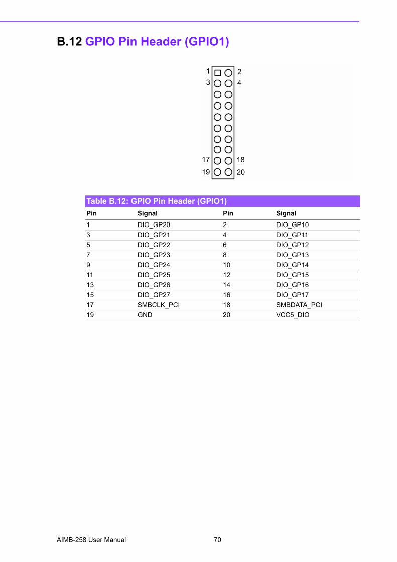
B.12 GPIO Pin Header (GPIO1)
Table B.12: GPIO Pin Header (GPIO1)Pin Signal Pin Signal1 DIO_GP20 2 DIO_GP103 DIO_GP21 4 DIO_GP115 DIO_GP22 6 DIO_GP127 DIO_GP23 8 DIO_GP139 DIO_GP24 10 DIO_GP1411 DIO_GP25 12 DIO_GP1513 DIO_GP26 14 DIO_GP1615 DIO_GP27 16 DIO_GP1717 SMBCLK_PCI 18 SMBDATA_PCI19 GND 20 VCC5_DIO
1 23 4
17 18
19 20
AIMB-258 User Manual 70
Appendix B
Pin A
ssignments
B.13 LVDS Connector (LVDS1)
Table B.13: LVDS Connector (LVDS1)Pin Signal Pin Signal1 VDDSAFE_1 2 VDDSAFE_23 GND_1 4 GND_75 VDDSAFE_3 6 VDDSAFE_47 OD0- 8 ED0-9 OD0+ 10 ED0+11 GND_2 12 GND_813 OD1- 14 ED1-15 OD1+ 16 ED1+17 GND_3 18 GND_919 OD2- 20 ED2-21 OD2+ 22 ED2+23 GND_4 24 GND_1025 OCK- 26 ECK-27 OCK+ 28 ECK+29 GND_5 30 GND_1131 DDC_CLK 32 DDC_DAT33 GND_6 34 GND_1235 OD3- 36 ED3-37 OD3+ 38 ED3+39 HPLG 40 VCON
2 4 3840
71 AIMB-258 User Manual
B.14 LVDS Power Jumper (J1)
*default setting
B.15 LVDS Invert (VP1)
Table B.14: LVDS Power Jumper (J1)Pin Signal1 VCC32 VDD_LCD3 VCC
3
1
2
3
1
2
*3.3V
5V
Voltage Jumper Setting
Table B.15: LVDS Invert (VP1)Pin Signal1 VCC122 GND3 BKLTEN4 VBR5 VCC
AIMB-258 User Manual 72
Appendix B
Pin A
ssignments
B.16 System I/O Ports
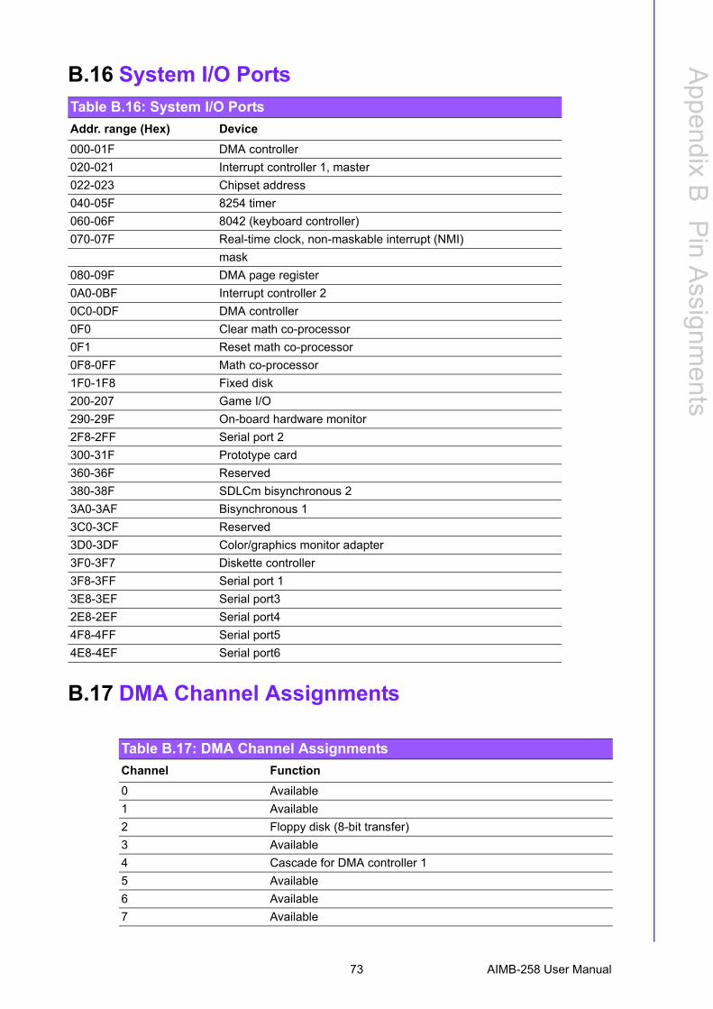
B.17 DMA Channel Assignments
Table B.16: System I/O PortsAddr. range (Hex) Device000-01F DMA controller020-021 Interrupt controller 1, master022-023 Chipset address040-05F 8254 timer060-06F 8042 (keyboard controller)070-07F Real-time clock, non-maskable interrupt (NMI)
mask080-09F DMA page register0A0-0BF Interrupt controller 20C0-0DF DMA controller0F0 Clear math co-processor0F1 Reset math co-processor0F8-0FF Math co-processor1F0-1F8 Fixed disk200-207 Game I/O290-29F On-board hardware monitor2F8-2FF Serial port 2300-31F Prototype card360-36F Reserved380-38F SDLCm bisynchronous 23A0-3AF Bisynchronous 13C0-3CF Reserved3D0-3DF Color/graphics monitor adapter3F0-3F7 Diskette controller3F8-3FF Serial port 13E8-3EF Serial port32E8-2EF Serial port44F8-4FF Serial port54E8-4EF Serial port6
Table B.17: DMA Channel AssignmentsChannel Function0 Available1 Available2 Floppy disk (8-bit transfer)3 Available4 Cascade for DMA controller 15 Available6 Available7 Available
73 AIMB-258 User Manual
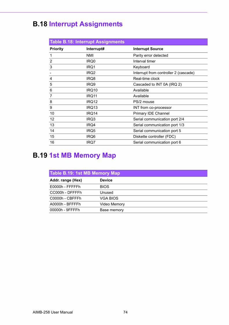
B.18 Interrupt Assignments
B.19 1st MB Memory Map
Table B.18: Interrupt AssignmentsPriority Interrupt# Interrupt Source1 NMI Parity error detected2 IRQ0 Interval timer3 IRQ1 Keyboard- IRQ2 Interrupt from controller 2 (cascade)4 IRQ8 Real-time clock5 IRQ9 Cascaded to INT 0A (IRQ 2)6 IRQ10 Available7 IRQ11 Available8 IRQ12 PS/2 mouse9 IRQ13 INT from co-processor10 IRQ14 Primary IDE Channel12 IRQ3 Serial communication port 2/413 IRQ4 Serial communication port 1/314 IRQ5 Serial communication port 515 IRQ6 Diskette controller (FDC)16 IRQ7 Serial communication port 6
Table B.19: 1st MB Memory MapAddr. range (Hex) DeviceE0000h - FFFFFh BIOSCC000h - DFFFFh UnusedC0000h - CBFFFh VGA BIOSA0000h - BFFFFh Video Memory00000h - 9FFFFh Base memory
AIMB-258 User Manual 74

Appendix B
Pin A
ssignments
75 AIMB-258 User Manual

www.advantech.comPlease verify specifications before quoting. This guide is intended for referencepurposes only.All product specifications are subject to change without notice.No part of this publication may be reproduced in any form or by any means,electronic, photocopying, recording or otherwise, without prior written permis-sion of the publisher.All brand and product names are trademarks or registered trademarks of theirrespective companies.© Advantech Co., Ltd. 2009


