Page 1
REVISIONS
DATE
CHK'D BY
DRWN BY
DATE
CLIENT
JOB NO.
SHEET NO.
OF
SD
S-C
AD
Sp
ecia
lize
d D
esig
n S
yste
ms
@COPYRIGHT SDSCAD Specialized Design Systems
P O
Bo
x 3
74
Me
nd
on
, U
tah
w
ww
.sd
sca
d.c
om
e
ma
il: s
dsca
d@
pcu
.ne
t
Re
sid
en
tia
l D
esig
n
To the best of my knowledge these plans are
drawn to comply with owner's and/ or builder's
specifications and any changes made on them
after prints are made will be done at the owner's
and / or builder's expence and responsibility. The
contractor shall verify all dimensions and enclosed
drawing. SDSCAD is not liable for errors once
construction has begun. While every affort has
been made in the preparation of this plan to avoid
mistakes, the maker can not guarantee against
human error. The contractor of the job must check
all dimensions and other details prior to
construction and be solely responsible thereafter.
All calculations and member sizing should be
verified for your building by a certified building
official.
1
11Note: Paper size B - 11 x 17 if printed on D - 22 x 34 scale is 2 X of stated scale
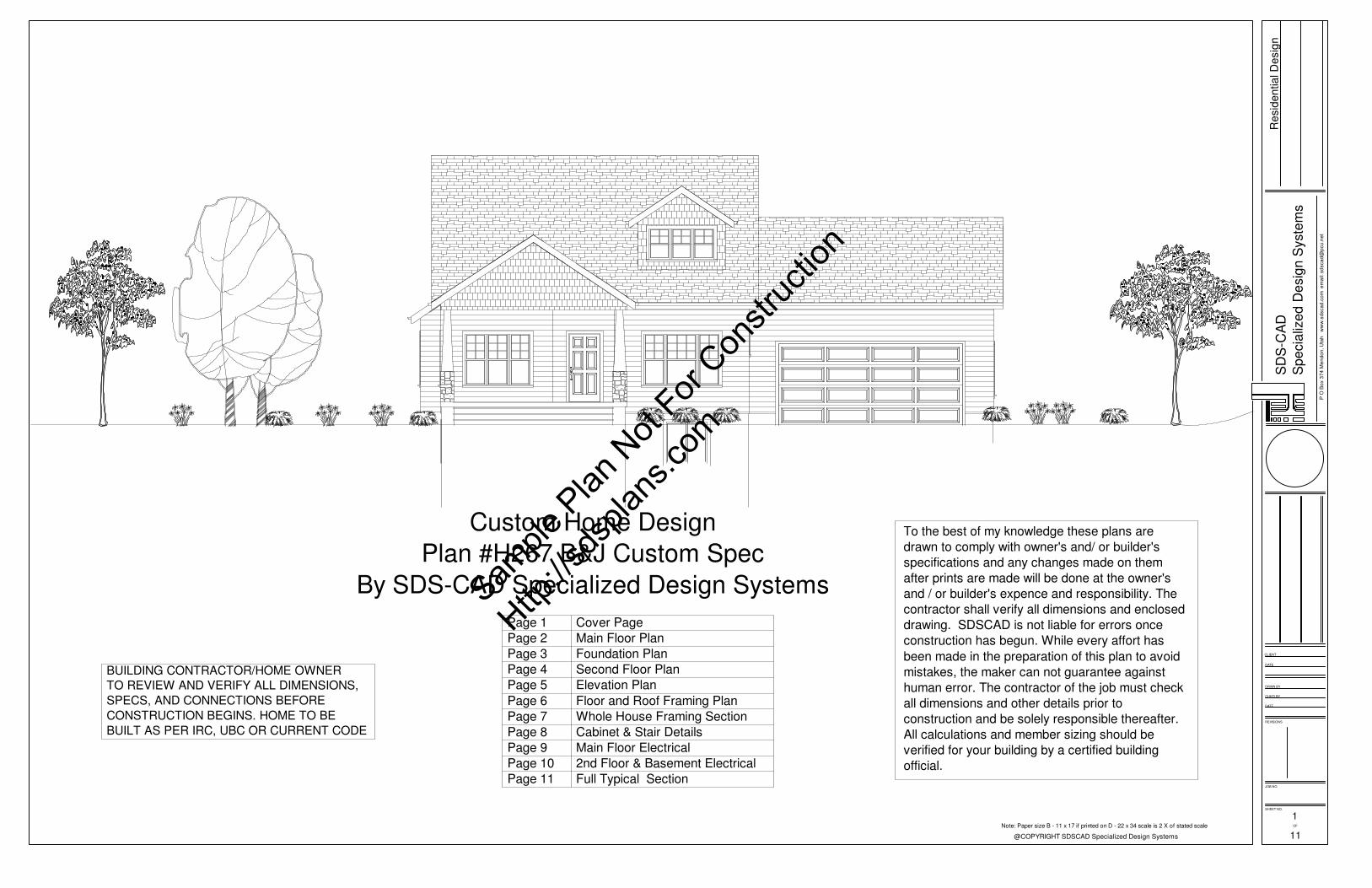
Custom Home Design
Plan #H267 B&J Custom Spec
By SDS-CAD Specialized Design Systems
Page 1 Cover Page
Page 2 Main Floor Plan
Page 3 Foundation Plan
Page 4 Second Floor Plan
Page 5 Elevation Plan
Page 6 Floor and Roof Framing Plan
Page 7 Whole House Framing Section
Page 8 Cabinet & Stair Details
Page 9 Main Floor Electrical
Page 10 2nd Floor & Basement Electrical
Page 11 Full Typical Section
BUILDING CONTRACTOR/HOME OWNER
TO REVIEW AND VERIFY ALL DIMENSIONS,
SPECS, AND CONNECTIONS BEFORE
CONSTRUCTION BEGINS. HOME TO BE
BUILT AS PER IRC, UBC OR CURRENT CODE
Sample
Plan
Not
For Con
struc
tion
Http://s
dspla
ns.co
m
Page 2
REVISIONS
DATE
CHK'D BY
DRWN BY
DATE
CLIENT
JOB NO.
SHEET NO.
OF
SD
S-C
AD
Sp
ecia
lize
d D
esig
n S
yste
ms
@COPYRIGHT SDSCAD Specialized Design Systems
P O
Bo
x 3
74
Me
nd
on
, U
tah
w
ww
.sd
sca
d.c
om
e
ma
il: s
dsca
d@
pcu
.ne
t
Re
sid
en
tia
l D
esig
n
DN
6068 2030 3068
30
50
205020502050
3068
205030502050
20
20
20
20
20
20
18080
30
50
30
68
2868
2668
40
68
26689068
20
50
20
50
20
50
30
30
2468
22
68
UP
DN
DN
LIVING16'-7" x 13'-0"
KITCHEN14'-2" x 15'-7"
GARAGE23'-5" x 22'-0"
MASTER BATH10'-11" x 9'-1"
MASTER BDRM12'-0" x 14'-10"
CLOSET5'-1" x 6'-1"
BATH7'-1" x 2'-11"
MUD
ROOM14'-5" x 5'-5"
PORCH17'-0" x 6'-4"
LIVING AREA1159 sq ft
DINING16'-0" x 9'-0"
4'-4"
9'-4"
15'-6"
2'-9"
3'-0"
2'-0"
2'-0"
2'-0"
2'-0"
2'-0"
2'-6"
41'-3"
23'-0"
10'-0"
3'-0"
10'-0"
1'-0"
41'-3"
15'-11"
10'-0"
13'-4"
1'-0"
7'-1"
3'-0"
5'-10"
1'-10"
2'-0"
2"
2'-0"
2"
2'-0"
1'-10"
4'-4"
3'-0"
6'-0"
56'-0"
24'-3"7'-7"2'-2"20'-0"2'-0"
2'-0"6'-0"12'-0" 17'-11"3'-0"3'-4"2'-10"2'-0"2'-9"
24'-0"
3'-0" 18'-0" 3'-0"
56'-0"
2'-0" 11'-0" 6'-0" 13'-0"
2'-4" 2'-0"2"
2'-0"2"
2'-0" 2'-4"1'-6"
3'-0"1'-6"
2'-10" 2'-0"2"
3'-0"2"
2'-0" 2'-10"
2'-8"
3'-0"
1'-6"2'-4"
6'-2"
5'-2"
11'-0"
4'-0"
7'-4"
14'-0"
16'-8"
3'-0"
2'-3"
4'-10"
1'-0"
3'-6"
6'-7"
2'-9"
3'-8"
LOCKERS
POSTPOST
TRANSOM
9 FOOT CEILINGS
VENTING SCHEDULERange Hoods Vent Through Roof
All Bath Fans Vent to Exterior
Dryer Vent Vent to Exterior
ATTIC VENTILATION:
AREA / 300
PROVIDE 1" MIN. AIR GAP AT
EAVES WITH INSULATION
BAFFELS TYP. AT ALL TRUSS
BAYS.
PROVIDE GABLE VENTS ALL
GABLE ENDS.
PROVIDE GALV. ROOF VENTS
ON BACKSIDE OF ROOFLINE
ABOVE CONDITIONED AREA.
2
11
SCALE 1/8"=1'
MAIN FLOOR PLAN
Note: Paper size B - 11 x 17 if printed on D - 22 x 34 scale is 2 X of stated scale
HOUSE WALLS 20" x 9" Min
DECKS & PORCHES 18" x 9" Min
BEARING WALL 20" x 9" Min
GARAGE WALL 18" x 9" Min
Min 2 #4 Rebar Horizontal
on undisturbed or compacted soil
FOOTING SCHEDULE
Ceilings R-49 Min
Wall above grade R-21 Min
Wall interior below grade R-13 Min
INSULATION SCHEDULE
Sample
Plan
Not
For Con
struc
tion
Http://s
dspla
ns.co
m
Page 3
REVISIONS
DATE
CHK'D BY
DRWN BY
DATE
CLIENT
JOB NO.
SHEET NO.
OF
SD
S-C
AD
Sp
ecia
lize
d D
esig
n S
yste
ms
@COPYRIGHT SDSCAD Specialized Design Systems
P O
Bo
x 3
74
Me
nd
on
, U
tah
w
ww
.sd
sca
d.c
om
e
ma
il: s
dsca
d@
pcu
.ne
t
Re
sid
en
tia
l D
esig
n
4040
2868
40
40
40
40
40
40
60
68
40
68
S
S
S
S
S
S
WH
UP
GARAGE23'-4" x 21'-8"
LIVING AREA1319 sq ft
UTILITY4'-10" x 5'-11"
STORAGE16'-8" x 6'-4"
5'-6" 2'-8" 3'-6"
6'-4"
6'-7"
8'-4"2'-10"
46'-3"
16'-3"
22'-8"
7'-4"
6'-4"
4'-0"
5'-11"
3'-6"
4'-0"
5'-8"
4'-0"
5'-6"
54'-0"
24'-4"14'-10"14'-10"
5'-0"
18'-3"
23'-0"
24'-0"
30'-0"
18'-0" 12'-0"
4'-0" 4'-0" 4'-0"
1'-6"
5'-0"
6'-0"
6'-0"
15'-6"
1'-0"
12'-0"
12' BEAM IN FLOOR BEAM IN
FLOOR
END
LENGTH
CUT
LENGTH
CLEARSPAN
END
LENGTH
Provide minimum 1"
end distance
Equal number of
specified nails in
each end Simpson Strong-Tie
CS16
NAIL BOTTOM TO SILL PLATE.
EDGES @12" O.C. IN FIELD.
NAIL W/8d NAILS @6" O.C.
4X8 SHT. ON FOUNDATION.
BRACED WALL PANEL
PROVIDE (2) STRAPS FOR B.W.P.
ALTERNATE BRACE WALL PANELS
Simpson HPAHD strap location marker
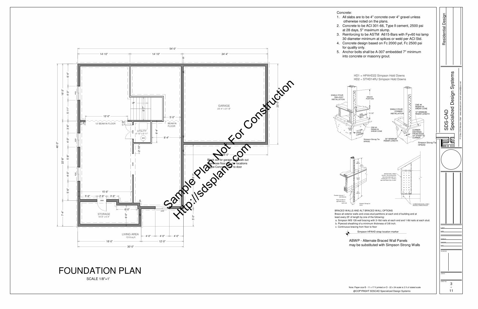
BRACED WALLS AND ALT BRACED WALL OPTIONS
Brace all exterior walls and cross-stud partitions at each end of building and at
least every 25' of length by one of the following:
a. Simpson WB 126 wall bracing with 3-16d nails at each end and 1-8d nails at each stud.
b. Plywood sheathing of a minimum thickness of 3/8 inch.
c. Continuous bracing from floor to floor
SEE
FOOTNOTE
NO.5
1/2" MIN.
FROM
CORNER
ONE #4REBAR INSHEAR CONE
NAILEDPORTION
13 1/2"
SINGLE POUR
RIM JOISTINSTALLATION
Simpson Strong-Tie
HPAHD
ONE #4REBAR INSHEAR CONE
12" MINIMUMREBAR LENGTH
30" MINIMUMREBAR LENGTH
FROM EDGEDISTANCECORNER
OF STRAP TOCORNER
Simpson Strong-TieHPAHD
SINGLE POURCORNER
INSTALLATION
HD1 = HPAHD22 Simpson Hold Downs
HD2 = STHD14RJ Simpson Hold Downs
Concrete:
1. All slabs are to be 4" concrete over 4" gravel unless
otherwise noted on the plans.
2. Concrete to be ACI 301-66, Type II cement, 2500 psi
at 28 days, 5" maximum slump.
3. Reinforcing to be ASTM A615-Bars with Fy=60 ksi lamp
30 diameter minimum at splices or weld per ACI Std.
4. Concrete design based on Fc 2000 psf, Fc 2500 psi
for quality only.
5. Anchor bolts shall be A-307 embedded 7" minimum
into concrete or masonry grout.
3
11
SCALE 1/8"=1'
FOUNDATION PLAN
Note: Paper size B - 11 x 17 if printed on D - 22 x 34 scale is 2 X of stated scale
Block out for garage and walk out
doors see floor plan for locations
Slope Concrete floor to door
ABWP - Alternate Braced Wall Panels
may be substituted with Simpson Strong Walls
Sample
Plan
Not
For Con
struc
tion
Http://s
dspla
ns.co
m
Page 4
REVISIONS
DATE
CHK'D BY
DRWN BY
DATE
CLIENT
JOB NO.
SHEET NO.
OF
SD
S-C
AD
Sp
ecia
lize
d D
esig
n S
yste
ms
@COPYRIGHT SDSCAD Specialized Design Systems
P O
Bo
x 3
74
Me
nd
on
, U
tah
w
ww
.sd
sca
d.c
om
e
ma
il: s
dsca
d@
pcu
.ne
t
Re
sid
en
tia
l D
esig
n
DN
30
50
30
50
30
50
203020302030
2030 2030 2030
26
68
2868 2668 2868
60
68
60
68
BEDROOM10'-11" x 16'-3"
LIVING AREA699 sq ft
LIVING14'-0" x 10'-8" BATH
5'-0" x 7'-8"C
LO
SE
T2
'-3
" x 9
'-1
1"BEDROOM
12'-5" x 12'-2"
CL
OS
ET
2'-3
" x 9
'-1
1"
54'-0"
30'-0" 24'-0"
46'-3"
5'-2 3
/4"
8'-0 1
/4"
12'-8"
11'-1"
9'-3"
6'-4"
3'-0"
3'-4"
3'-0"
3'-0"
5'-1"
10'-0"
8'-3"
5'-0"
1'-0"
3'-0"
6'-0"
23'-0"
24'-0"
30'-0"
12'-0"18'-0"
2'-0"
9'-0"
12'-0"8'-4"3'-0"
4'-0"
8'-4" 2'-4"
4'-0"
9'-5" 2'-8"1'-0"8"
2'-6"8"1'-6"1'-0"
2'-8"
2'-8"
2'-0"
2'-0"
5'-5"
9 FOOT CEILINGS
DOOR SCHEDULE
NUMBER QTY FLOOR SIZE DIMENSIONS WIDTH HEIGHT
D01 1 0 2868 32X80X1 3/8" 32 " 80 "
D02 1 0 4068 24X80X1 3/8" 24 " 80 "
D03 1 1 18080 216X96" 216 " 96 "
D04 1 1 2268 26X80X1 3/8" 26 " 80 "
D05 1 1 2468 28X80X1 3/8" 28 " 80 "
D06 2 1 2668 30X80X1 3/8" 30 " 80 "
D07 1 1 2868 32X80X1 3/8" 32 " 80 "
D08 3 1 3068 36X80X1 3/4" 36 " 80 "
D09 1 1 4068 24X80X1 3/8" 24 " 80 "
D10 1 1 6068 72X80" 72 " 80 "
D11 2 2 2668 30X80X1 3/8" 30 " 80 "
D12 2 2 2868 32X80X1 3/8" 32 " 80 "
D13 2 2 6068 72X80" 72 " 80 "
WINDOW SCHEDULE
NUMBER QTY FLOOR SIZE DIMENSIONS WIDTH HEIGHT
W01 4 0 4040 48"X48" 48 " 48 "
W02 3 1 2020 24"X24" 24 " 24 "
W03 1 1 2030 24"X36" 24 " 36 "
W04 8 1 2050 24"X60" 24 " 60 "
W05 1 1 3030 36"X36" 36 " 36 "
W06 3 1 3050 36"X60" 36 " 60 "
W07 6 2 2030 24"X36" 24 " 36 "
W08 3 2 3050 36"X60" 36 " 60 "
CABINET SCHEDULE
NUMBER QTY FLOOR DIMENSIONS WIDTH DEPTH HEIGHT DESCRIPTION
C01 1 1 18X24X36 " 18 " 24 " 36 " BATH BASE CAB
C02 1 1 18X24X36 " 18 " 24 " 36 " KIT. BASE CAB
C03 2 1 24X24X36 " 24 " 24 " 36 " BATH BASE CAB
C04 1 1 30X12X30 " 30 " 12 " 30 " KIT. WALL CAB
C05 1 1 30X24X36 " 30 " 24 " 36 " KIT. BASE CAB
C06 1 1 33X24X36 " 33 " 24 " 36 " BATH BASE CAB
C07 2 1 36X24X36 " 36 " 24 " 36 " PEN BASE CAB
C08 1 2 24X24X36 " 24 " 24 " 36 " BATH BASE CAB
C09 1 1 24X24X36 " 24 " 24 " 36 " KIT. BASE CAB
C10 1 1 21X24X36 " 21 " 24 " 36 " KIT. BASE CAB
C11 1 1 36X36X36 " 36 " 36 " 36 " CRNR BASE CAB
C12 1 1 24X24X30 " 24 " 24 " 30 " CRNR WALL CAB
C13 1 1 36X12X17 " 36 " 12 " 17 " KIT. WALL CAB
C14 1 1 18X12X30 " 18 " 12 " 30 " KIT. WALL CAB
C15 1 1 39X24X36 " 39 " 24 " 36 " KIT. BASE CAB
C16 1 1 33X24X36 " 33 " 24 " 36 " KIT. BASE CAB
C17 2 1 33X12X30 " 33 " 12 " 30 " KIT. WALL CAB
C18 1 1 36X12X30 " 36 " 12 " 30 " KIT. WALL CAB
11Note: Paper size B - 11 x 17 if printed on D - 22 x 34 scale is 2 X of stated scale
SECOND FLOOR PLANSCALE 1/8"=1'
4
Sample
Plan
Not
For Con
struc
tion
Http://s
dspla
ns.co
m
Page 5
REVISIONS
DATE
CHK'D BY
DRWN BY
DATE
CLIENT
JOB NO.
SHEET NO.
OF
SD
S-C
AD
Sp
ecia
lize
d D
esig
n S
yste
ms
@COPYRIGHT SDSCAD Specialized Design Systems
P O
Bo
x 3
74
Me
nd
on
, U
tah
w
ww
.sd
sca
d.c
om
e
ma
il: s
dsca
d@
pcu
.ne
t
Re
sid
en
tia
l D
esig
n
5
11
FRONT ELEVATIONSCALE 1/8"=1'
SCALE 1/16"=1'
RIGHT ELEVATION
ARCHITECTURAL
ASHPHALT
SHINGLES
Note: Paper size B - 11 x 17 if printed on D - 22 x 34 scale is 2 X of stated scale
SCALE 1/16"=1'
REAR ELEVATIONSCALE 1/16"=1'
LEFT ELEVATION
GRADE
Sample
Plan
Not
For Con
struc
tion
Http://s
dspla
ns.co
m
Page 6
REVISIONS
DATE
CHK'D BY
DRWN BY
DATE
CLIENT
JOB NO.
SHEET NO.
OF
SD
S-C
AD
Sp
ecia
lize
d D
esig
n S
yste
ms
@COPYRIGHT SDSCAD Specialized Design Systems
P O
Bo
x 3
74
Me
nd
on
, U
tah
w
ww
.sd
sca
d.c
om
e
ma
il: s
dsca
d@
pcu
.ne
t
Re
sid
en
tia
l D
esig
n
DN
6068 2030 3068
3050
205020502050
3068
205030502050
2020
2020
2020
18080
3050
3068
2868
2668
4068
26689068
2050
2050
2050
3030
2468
2268
UP
DN
2x12 jois
ts 1
6"
OC
DN
4040
2868
4040
4040
4040
6068
4068
S
S
S
S
S
S
UP
2x12 joists 16" OC
GARAGE23'-4" x 21'-8"
UTILITY4'-10" x 5'-11"
STORAGE16'-8" x 6'-4"
DN
3050
3050
3050
203020302030
2030 2030 2030
2668
2868 2668 2868
6068
6068
BEARING
WALL
11 7/8" I-Joists 16" o.c
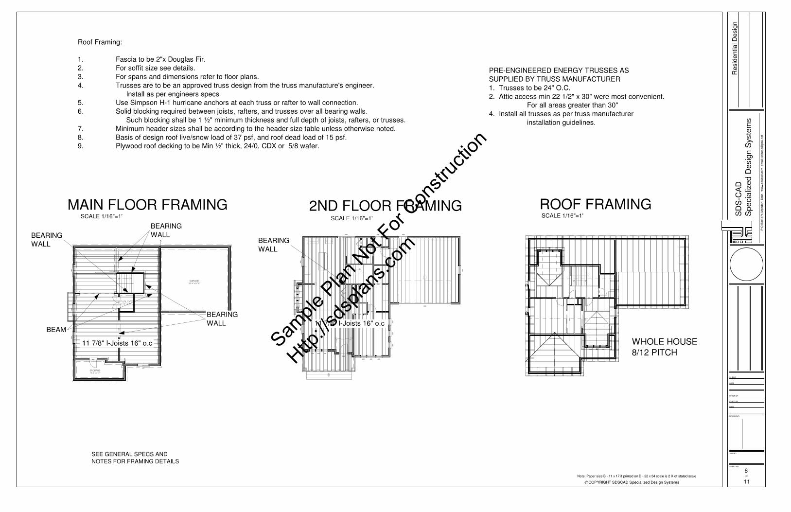
Roof Framing:
1. Fascia to be 2"x Douglas Fir.
2. For soffit size see details.
3. For spans and dimensions refer to floor plans.
4. Trusses are to be an approved truss design from the truss manufacture's engineer.
Install as per engineers specs
5. Use Simpson H-1 hurricane anchors at each truss or rafter to wall connection.
6. Solid blocking required between joists, rafters, and trusses over all bearing walls.
Such blocking shall be 1 ½" minimum thickness and full depth of joists, rafters, or trusses.
7. Minimum header sizes shall be according to the header size table unless otherwise noted.
8. Basis of design roof live/snow load of 37 psf, and roof dead load of 15 psf.
9. Plywood roof decking to be Min ½" thick, 24/0, CDX or 5/8 wafer.
6
11
SCALE 1/16"=1'
MAIN FLOOR FRAMINGSCALE 1/16"=1'
ROOF FRAMING
PRE-ENGINEERED ENERGY TRUSSES AS
SUPPLIED BY TRUSS MANUFACTURER
1. Trusses to be 24" O.C.
2. Attic access min 22 1/2" x 30" were most convenient.
For all areas greater than 30"
4. Install all trusses as per truss manufacturer
installation guidelines.
SEE GENERAL SPECS AND
NOTES FOR FRAMING DETAILS
Note: Paper size B - 11 x 17 if printed on D - 22 x 34 scale is 2 X of stated scale
SCALE 1/16"=1'
2ND FLOOR FRAMING
WHOLE HOUSE
8/12 PITCH
BEARING
WALL
BEARING
WALL
BEAM
BEARING
WALL
11 7/8" I-Joists 16" o.c
Sample
Plan
Not
For Con
struc
tion
Http://s
dspla
ns.co
m
Page 7
REVISIONS
DATE
CHK'D BY
DRWN BY
DATE
CLIENT
JOB NO.
SHEET NO.
OF
SD
S-C
AD
Sp
ecia
lize
d D
esig
n S
yste
ms
@COPYRIGHT SDSCAD Specialized Design Systems
P O
Bo
x 3
74
Me
nd
on
, U
tah
w
ww
.sd
sca
d.c
om
e
ma
il: s
dsca
d@
pcu
.ne
t
Re
sid
en
tia
l D
esig
n
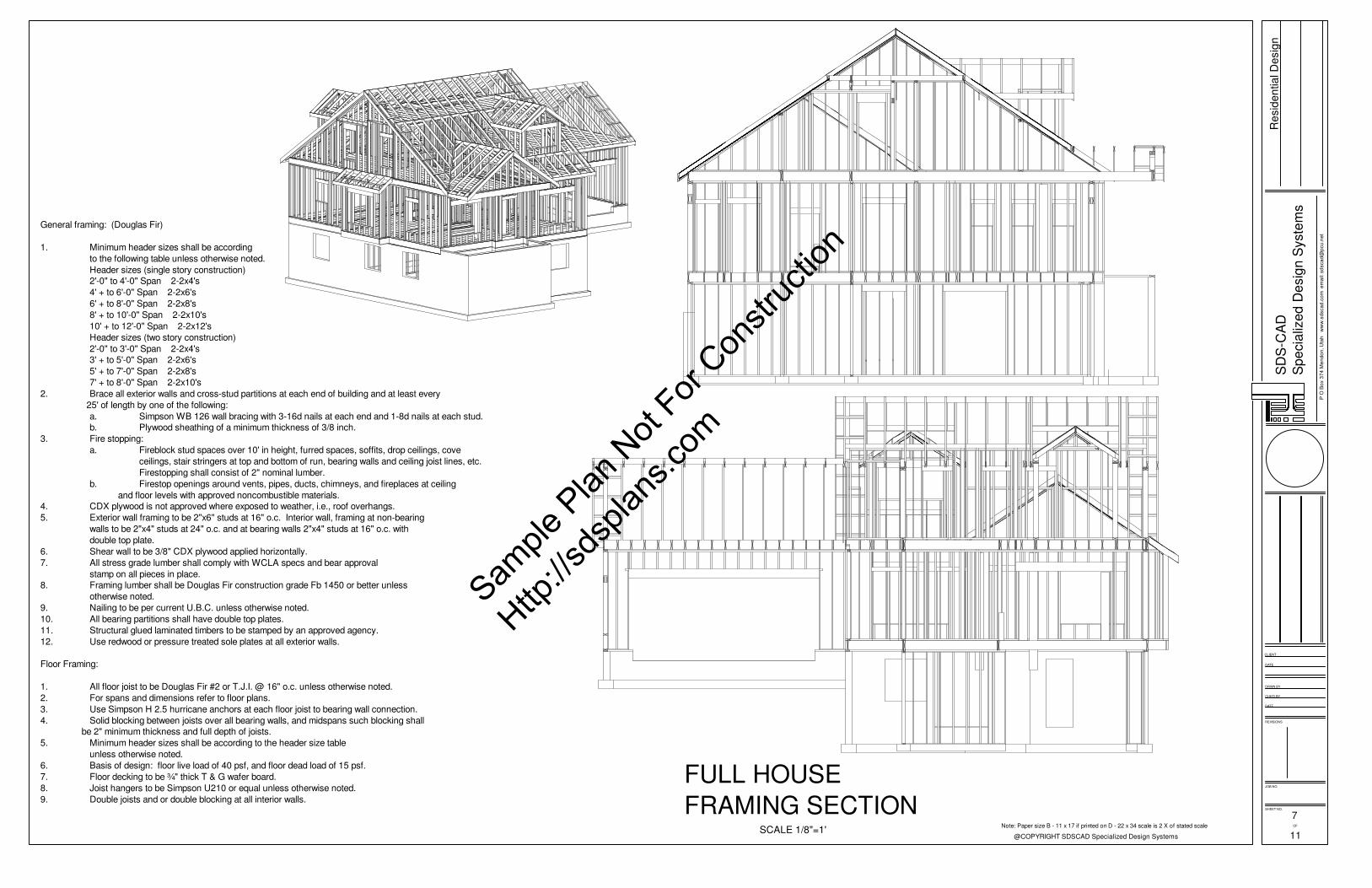
General framing: (Douglas Fir)
1. Minimum header sizes shall be according
to the following table unless otherwise noted.
Header sizes (single story construction)
2'-0" to 4'-0" Span 2-2x4's
4' + to 6'-0" Span 2-2x6's
6' + to 8'-0" Span 2-2x8's
8' + to 10'-0" Span 2-2x10's
10' + to 12'-0" Span 2-2x12's
Header sizes (two story construction)
2'-0" to 3'-0" Span 2-2x4's
3' + to 5'-0" Span 2-2x6's
5' + to 7'-0" Span 2-2x8's
7' + to 8'-0" Span 2-2x10's
2. Brace all exterior walls and cross-stud partitions at each end of building and at least every
25' of length by one of the following:
a. Simpson WB 126 wall bracing with 3-16d nails at each end and 1-8d nails at each stud.
b. Plywood sheathing of a minimum thickness of 3/8 inch.
3. Fire stopping:
a. Fireblock stud spaces over 10' in height, furred spaces, soffits, drop ceilings, cove
ceilings, stair stringers at top and bottom of run, bearing walls and ceiling joist lines, etc.
Firestopping shall consist of 2" nominal lumber.
b. Firestop openings around vents, pipes, ducts, chimneys, and fireplaces at ceiling
and floor levels with approved noncombustible materials.
4. CDX plywood is not approved where exposed to weather, i.e., roof overhangs.
5. Exterior wall framing to be 2"x6" studs at 16" o.c. Interior wall, framing at non-bearing
walls to be 2"x4" studs at 24" o.c. and at bearing walls 2"x4" studs at 16" o.c. with
double top plate.
6. Shear wall to be 3/8" CDX plywood applied horizontally.
7. All stress grade lumber shall comply with WCLA specs and bear approval
stamp on all pieces in place.
8. Framing lumber shall be Douglas Fir construction grade Fb 1450 or better unless
otherwise noted.
9. Nailing to be per current U.B.C. unless otherwise noted.
10. All bearing partitions shall have double top plates.
11. Structural glued laminated timbers to be stamped by an approved agency.
12. Use redwood or pressure treated sole plates at all exterior walls.
Floor Framing:
1. All floor joist to be Douglas Fir #2 or T.J.I. @ 16" o.c. unless otherwise noted.
2. For spans and dimensions refer to floor plans.
3. Use Simpson H 2.5 hurricane anchors at each floor joist to bearing wall connection.
4. Solid blocking between joists over all bearing walls, and midspans such blocking shall
be 2" minimum thickness and full depth of joists.
5. Minimum header sizes shall be according to the header size table
unless otherwise noted.
6. Basis of design: floor live load of 40 psf, and floor dead load of 15 psf.
7. Floor decking to be ¾" thick T & G wafer board.
8. Joist hangers to be Simpson U210 or equal unless otherwise noted.
9. Double joists and or double blocking at all interior walls.
7
11SCALE 1/8"=1'
FULL HOUSE
FRAMING SECTIONNote: Paper size B - 11 x 17 if printed on D - 22 x 34 scale is 2 X of stated scale
Sample
Plan
Not
For Con
struc
tion
Http://s
dspla
ns.co
m
Page 8
REVISIONS
DATE
CHK'D BY
DRWN BY
DATE
CLIENT
JOB NO.
SHEET NO.
OF
SD
S-C
AD
Sp
ecia
lize
d D
esig
n S
yste
ms
@COPYRIGHT SDSCAD Specialized Design Systems
P O
Bo
x 3
74
Me
nd
on
, U
tah
w
ww
.sd
sca
d.c
om
e
ma
il: s
dsca
d@
pcu
.ne
t
Re
sid
en
tia
l D
esig
n
8 '- 1 1 "
RUN 10" PER STAIR
RISE 8" PER STAIR
3'-6"
NEWEL POST
BALUSTERS MAX 4" SPACE.
32-34" GUARDRAIL
TO FIRST RISER.
ADD FIN. FLOOR THICKNESS
2 x 8 KICKER
MAIN FLOOR STAIR
3-2 x 12 STRINGERS
FIN
. F
LO
OR
TO
FIN
. F
LO
OR
2 x 10 DBL.
HEADERS
BD
R1
83
6C
BD
36
36
BD
R2
43
6B
D3
33
6B
S3
93
6
BDL2136 BD3036
PB
D3
63
6P
BD
36
36
W3030W3330
W3
61
7W
R1
83
0W
36
30
CW
24
30
W3
33
0
KITCHEN14'-2" x 15'-7"
3'-0"
3'-6"
STAIR DETAILS
STAIR SPECIFICATIONS
1. Stairs to be constructed with the following materials:
2x6 kick plate anchor to concrete with expansion type anchor bolts,
2x12 treads nosing 1 1/8" minimum, 3-2x12 stringers required,
2x12 blocking, ¾" wafer board risers and 2x6 ledger.
2. Handrail/Guardrails final style, material and color
to be owner's choice. Design to be per code.
3. Guardrails to be 42" high minimum from floor.
4. Handrails to be 34"-38" above tread nosing.
5. Open railing to have intermediate rails or ornamental
pattern such that a sphere 4" round cannot pass through.
6. Minimum stair requirements: maximum 8" rise, minimum 42" width,
minimum 9" run, minimum head clearance 6'-8".
7. Preferred stair requirements: rise 7" to 7 ½", run 11" to 12", minimum
head clearance 7'-0".
8. Garage entrance stairs may be concrete or wood as
per contractor/homeowner
8
11Note: Paper size B - 11 x 17 if printed on D - 22 x 34 scale is 2 X of stated scale
Kitchen layout and cabinets to be
chosen by homeowner/Contractor
basic layout for reference only.
Measure after sheetrock is installed
for correct sizing.
SCALE 1/4"=1'
Cabinet Detail
Sample
Plan
Not
For Con
struc
tion
Http://s
dspla
ns.co
m
Page 9
REVISIONS
DATE
CHK'D BY
DRWN BY
DATE
CLIENT
JOB NO.
SHEET NO.
OF
SD
S-C
AD
Sp
ecia
lize
d D
esig
n S
yste
ms
@COPYRIGHT SDSCAD Specialized Design Systems
P O
Bo
x 3
74
Me
nd
on
, U
tah
w
ww
.sd
sca
d.c
om
e
ma
il: s
dsca
d@
pcu
.ne
t
Re
sid
en
tia
l D
esig
n
DN
UP
DN
DN
SD
SD
GFCI3
WPWP
4
WP
WP
GFCI
33
4
43
3
3
ELECTRICAL SCHEDULE
NUMBER QTY FLOOR DESCRIPTION
E01 2 2 THREE WAY
E02 3 2 SMOKE DETECTOR
E03 4 2 SINGLE POLE
E04 5 2 HALF DOME LIGHT - LIGHTING GREY
E05 1 2 HALF CONE - LIGHTING GREY
E06 1 2 GFCI
E07 1 2 EXHAUST
E08 16 2 DUPLEX
E09 6 1 THREE WAY
E10 2 1 SMOKE DETECTOR
E11 12 1 SINGLE POLE
E12 7 1 PORCH LANTERN
E13 16 1 HALF DOME LIGHT - LIGHTING GREY
E14 3 1 HALF CONE - LIGHTING GREY
E15 3 1 FOUR WAY
E16 2 1 EXHAUST
E17 4 1 DUPLEX (WEATHERPROOF) - COLOR LIGHT GRAY (MATTE)
E18 30 1 DUPLEX
E19 2 1 220V
E20 2 0 SMOKE DETECTOR
E21 7 0 SINGLE POLE
E22 11 0 HALF DOME LIGHT - LIGHTING GREY
E23 24 0 DUPLEX
E24 2 1 GFCI
C
TV
SD
WP
GFI
4
3
DESCRIPTIONSYMBOL
ELECTRICAL LEGEND
DOOR CHIME
EXHAUST FAN
SMOKE DETECTOR
THERMOSTAT
DOOR BELL PUSH BUTTON
TELEVISION JACKS
TELEPHONE JACKS
240V RECEPTACLE
110VFLOOR MOUNTED
DUPLEX RECEPTACLE
METER SOCKET
PANEL BOX
CEILING FAN W/ LIGHT
FLUORESCENT LIGHT FIXTURE
110V CEILING LIGHT FIXTURE
110V RECESSED LIGHT FIXTURE
110V EAVE LIGHT FIXTURE
110V CHANDILIER LIGHT FIXTURE
110V WALL LIGHT FIXTURE
SINGLE POLE SWITCH
THREE WAY SWITCH
FOUR WAY SWITCH
DIMMER SWITCH
OUTDOOR SWITCH
110V DUPLEX RECEPTACLE
110V DUPLEX RECEPTACLE
GROUND FAULT INTERUPTED
110V DUPLEX RECEPTACLE
W/ WEATHERPROOF COVER
T
F
A FIRE ALARM PANEL
COMPUTER POINT
WP
DM
DC
9
11
SCALE 1/8"=1'
MAIN FLOOR
ELECTRICAL PLAN
Note: Paper size B - 11 x 17 if printed on D - 22 x 34 scale is 2 X of stated scale
Sample
Plan
Not
For Con
struc
tion
Http://s
dspla
ns.co
m
Page 10
REVISIONS
DATE
CHK'D BY
DRWN BY
DATE
CLIENT
JOB NO.
SHEET NO.
OF
SD
S-C
AD
Sp
ecia
lize
d D
esig
n S
yste
ms
@COPYRIGHT SDSCAD Specialized Design Systems
P O
Bo
x 3
74
Me
nd
on
, U
tah
w
ww
.sd
sca
d.c
om
e
ma
il: s
dsca
d@
pcu
.ne
t
Re
sid
en
tia
l D
esig
n
DN
SDSD
SD
GFCI
3
3
S
S
S
S
S
S
WH
UP
SD
SD
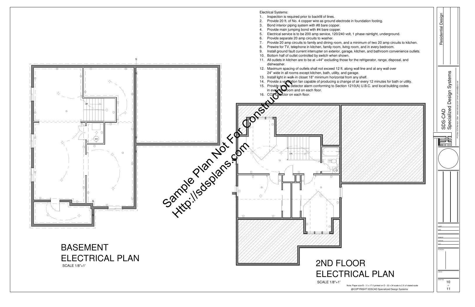
Electrical Systems:
1. Inspection is required prior to backfill of lines.
2. Provide 20 ft. of No. 4 copper wire as ground electrode in foundation footing.
3. Bond interior piping system with #8 bare copper.
4. Provide main jumping bond with #4 bare copper.
5. Electrical service is to be 200 amp service, 120/240 volt, 1 phase raintight, underground.
6. Provide separate 20 amp circuits to washer.
7. Provide 20 amp circuits to family and dining room, and a minimum of two 20 amp circuits to kitchen.
8. Prewire for TV, telephone in kitchen, family room, living room, and in every bedroom.
9. Install ground fault current interrupter on exterior, garage, kitchen, and bathroom convenience outlets.
10. Bottom half of outlet controlled by switch when shown.
11. All outlets in kitchen are to be at +44" excluding those for the refrigerator, range, disposal, and
dishwasher.
12. Maximum spacing of outlets shall not exceed 12 ft. along wall line and at any wall over
24" wide in all rooms except kitchen, bath, utility, and garage.
13. Install light in walk-in closet 18" minimum horizontal from any shelf.
14. Provide a ventilation fan capable of producing a change of air every 12 minutes for bath or utility.
15. Provide smoke detector alarm conforming to Section 1210(A) U.B.C. and local building codes
in every bedroom and on each floor.
16. CO2 Detector on each floor.
11
SCALE 1/8"=1'
BASEMENT
ELECTRICAL PLAN
Note: Paper size B - 11 x 17 if printed on D - 22 x 34 scale is 2 X of stated scale
2ND FLOOR
ELECTRICAL PLANSCALE 1/8"=1' 10
Sample
Plan
Not
For Con
struc
tion
Http://s
dspla
ns.co
m
Page 11
REVISIONS
DATE
CHK'D BY
DRWN BY
DATE
CLIENT
JOB NO.
SHEET NO.
OF
SD
S-C
AD
Sp
ecia
lize
d D
esig
n S
yste
ms
@COPYRIGHT SDSCAD Specialized Design Systems
P O
Bo
x 3
74
Me
nd
on
, U
tah
w
ww
.sd
sca
d.c
om
e
ma
il: s
dsca
d@
pcu
.ne
t
Re
sid
en
tia
l D
esig
n
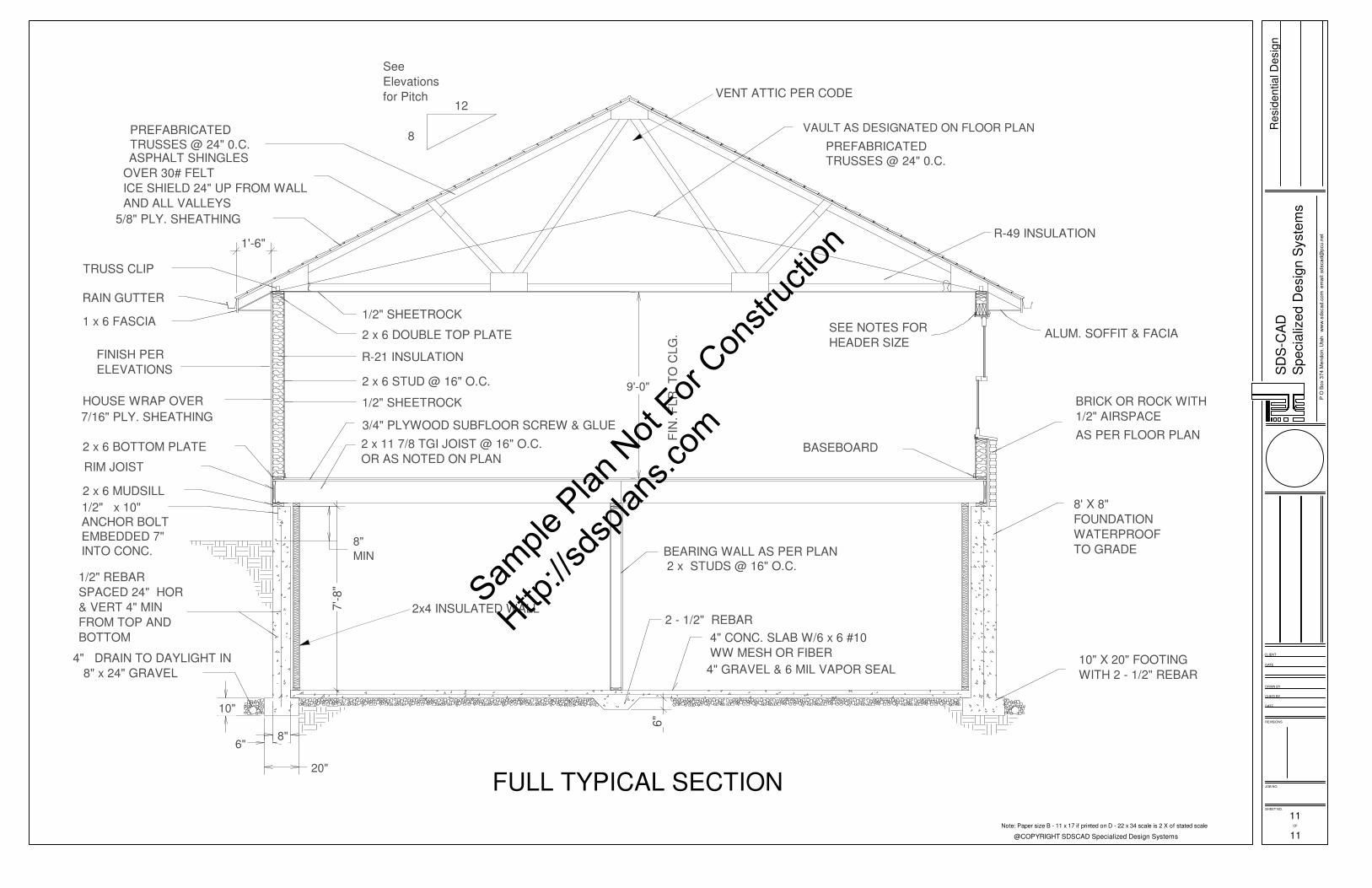
8
2x4 INSULATED WALL
VAULT AS DESIGNATED ON FLOOR PLAN
4" GRAVEL & 6 MIL VAPOR SEAL
4" CONC. SLAB W/6 x 6 #10
WW MESH OR FIBER
SEE NOTES FOR
HEADER SIZE
BASEBOARD
PREFABRICATED
TRUSSES @ 24" 0.C.
7'-8"
8" x 24" GRAVEL
1/2" REBAR
SPACED 24" HOR
& VERT 4" MIN
FROM TOP AND
BOTTOM
4" DRAIN TO DAYLIGHT IN
10"
6"
20"
8"
6"
3/4" PLYWOOD SUBFLOOR SCREW & GLUE
2 x 11 7/8 TGI JOIST @ 16" O.C.
OR AS NOTED ON PLAN
1/2" SHEETROCK
2 x 6 STUD @ 16" O.C.
R-21 INSULATION
2 x 6 DOUBLE TOP PLATE
1/2" SHEETROCK
RIM JOIST
INTO CONC.
EMBEDDED 7"
ANCHOR BOLT
1/2" x 10"
2 x 6 MUDSILL
7/16" PLY. SHEATHING
HOUSE WRAP OVER
2 x 6 BOTTOM PLATE
RAIN GUTTER
FINISH PER
ELEVATIONS
1 x 6 FASCIA
TRUSS CLIP
8"
MIN
5/8" PLY. SHEATHING
TRUSSES @ 24" 0.C.
PREFABRICATED
ASPHALT SHINGLES
1'-6"
OVER 30# FELT
ICE SHIELD 24" UP FROM WALL
AND ALL VALLEYS
9'-0"
FIN
. F
LR
. T
O C
LG
.
2 x STUDS @ 16" O.C.
BEARING WALL AS PER PLAN
See
Elevations
for Pitch12
10" X 20" FOOTING
WITH 2 - 1/2" REBAR
BRICK OR ROCK WITH
1/2" AIRSPACE
8' X 8"
FOUNDATION
WATERPROOF
TO GRADE
ALUM. SOFFIT & FACIA
AS PER FLOOR PLAN
R-49 INSULATION
2 - 1/2" REBAR
VENT ATTIC PER CODE
11Note: Paper size B - 11 x 17 if printed on D - 22 x 34 scale is 2 X of stated scale
11
FULL TYPICAL SECTION
Sample
Plan
Not
For Con
struc
tion
Http://s
dspla
ns.co
m