For ConTech Lighting Lux Beam Track System www.contechlighting.com 1-847-559-5500 This document can be recycled. LUXBM INST B Steel Toggle Cable Coupler 5/64" Cable 1/4"-20 Stud Internal Tooth-Lock Washer Cable Holder with Lock Nut Ceiling Canopy Bracket Bar with Ground Screw 1/4-20 x 3/8" Bolt LUX BEAM INSTALLATION INSTRUCTIONS: 1. Unpack all components and sort by type. The beams should be sorted by size, track and blank configurations. The connec- tors/power feeds are in straight, 90°, “T” and “X” configurations. Using the layout drawings and packing list, check to make sure all parts are present. Contact the factory if any parts are missing. Aircraft cables, if specified, and power feeds will be in 10' and 20' lengths. 2. Using the layout drawing, locate the connector/power feed positions. It may be necessary to mount unistrut or other supports in the ceiling to accept the aircraft cables at the correct locations. It is very important that exact centers for the supports are provided. Failure to do so will result in considerable difficulty with the final alignment. The on-center dimensions for standard beam sizes are 2', 4', 6' and 8' accordingly. Additional support materials are not included and must be provided by others. INSTALLING THE SUSPENSION CABLES: Hang the suspension cables or rods at the centers as specified in Step 2. CEILING CANOPY 1. Secure 1/4"-20 stud to ceiling or support structure using included bracket bar or other acceptable hardware. 2. Feed cable length through Cable Coupler so the starter crimp seats within. (SEE FIGURE 1A) 3. Place Canopy (if needed) over 1/4"-20 stud then attach Cable Coupler to 1/4"-20 stud leaving cable length to hang free. LOOP AROUND STRUCTURE (UNISTRUT) 1. Insert cable through the Steel Toggle. (SEE FIGURE1B) 2. Loop cable over support structure, then back through hole in Steel Toggle below to create a loop leaving remaining cable length to hang free. CONTINUED ON PAGE 2 A INSTALLATION INSTRUCTIONS All specifications subject to change without notice. For ConTech’s limited product warranty, go to www.contechlighting.com. For a printed copy of the warranty, call 1-847-559-5500.
Transcript
For ConTech Lighting Lux Beam Track System
www.contechlighting.com1-847-559-5500 This document can be recycled. LUXBM INST
B
SteelToggle
Cable Coupler
5/64" Cable
1/4"-20 Stud
Internal Tooth-Lock Washer
Cable Holderwith Lock Nut
Ceiling Canopy
Bracket Bar with Ground Screw
1/4-20 x 3/8" Bolt
LUX BEAM
INSTALLATION INSTRUCTIONS:1. Unpack all components and sort by type. The beams should be
sorted by size, track and blank configurations. The connec-tors/power feeds are in straight, 90°, “T” and “X” configurations. Using the layout drawings and packing list, check to make sure all parts are present. Contact the factory if any parts are missing. Aircraft cables, if specified, and power feeds will be in 10' and 20' lengths.
2. Using the layout drawing, locate the connector/power feed positions. It may be necessary to mount unistrut or other supports in the ceiling to accept the aircraft cables at the correct locations. It is very important that exact centers for the supports are provided. Failure to do so will result in considerable difficulty with the final alignment. The on-center dimensions for standard beam sizes are 2', 4', 6' and 8' accordingly. Additional support materials are not included and must be provided by others.
INSTALLING THE SUSPENSION CABLES:Hang the suspension cables or rods at the centers as specified in Step 2.CEILING CANOPY 1. Secure 1/4"-20 stud to ceiling or support structure using
included bracket bar or other acceptable hardware. 2. Feed cable length through Cable Coupler so the starter crimp
seats within. (SEE FIGURE 1A) 3. Place Canopy (if needed) over 1/4"-20 stud then attach Cable
Coupler to 1/4"-20 stud leaving cable length to hang free. LOOP AROUND STRUCTURE (UNISTRUT) 1. Insert cable through the Steel Toggle. (SEE FIGURE1B) 2. Loop cable over support structure, then back through hole in
Steel Toggle below to create a loop leaving remaining cable length to hang free.
CONTINUED ON PAGE 2
A
INSTALLATION INSTRUCTIONS
All specifications subject to change without notice. For ConTech’s limited product warranty, go to www.contechlighting.com. For a printed copy of the warranty, call 1-847-559-5500.
For ConTech Lighting Lux Beam Track System
www.contechlighting.com1-847-559-5500 This document can be recycled. LUXBM INST
INSTALLING THE CONNECTOR/POWER FEEDS:1. Prepare the connector/power feeds for installation by removing
the (2) Philips head screws and square plates on the bottom of each one. (SEE FIGURE 2) Do not throw away, these will be reinstalled later.
2. If using aircraft cable, install the cable holder (gripper) to the connector/power feed assembly using the internal tooth lock washer and 1/4"-20 screw threaded into the bottom of the cable holder as shown. (SEE FIGURE 3)
3. Using a laser or other measuring device, hang the connector/ power feeds at their specified locations and heights. When using aircraft cable, the cable should be inserted in the top of and through the cable holder assembly as shown. Make sure knurled locking nut is fully backed off to ensure full travel for cable insertion. (SEE FIGURE 4)
4. Excess cable should be left alone at this time and should only be trimmed after final height adjustment.
5. For threaded rod installation, place a nut on the rod before inserting it into the 1/4" hole in the top center of each connector, then place another nut under the connector.
CONTINUED ON PAGE 33
4
INSTALLATION INSTRUCTIONS
All specifications subject to change without notice. For ConTech’s limited product warranty, go to www.contechlighting.com. For a printed copy of the warranty, call 1-847-559-5500.
For ConTech Lighting Lux Beam Track System
www.contechlighting.com1-847-559-5500 This document can be recycled. LUXBM INST
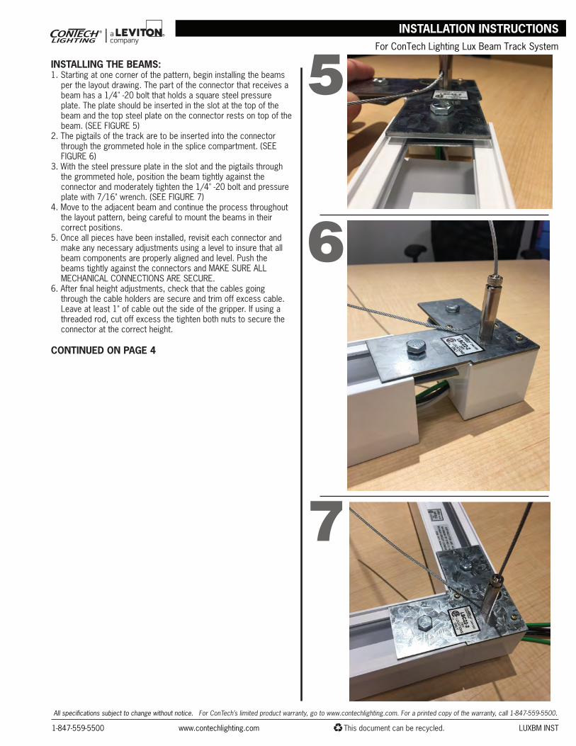
INSTALLING THE BEAMS:1. Starting at one corner of the pattern, begin installing the beams
per the layout drawing. The part of the connector that receives a beam has a 1/4" -20 bolt that holds a square steel pressure plate. The plate should be inserted in the slot at the top of the beam and the top steel plate on the connector rests on top of the beam. (SEE FIGURE 5)
2. The pigtails of the track are to be inserted into the connector through the grommeted hole in the splice compartment. (SEE FIGURE 6)
3. With the steel pressure plate in the slot and the pigtails through the grommeted hole, position the beam tightly against the connector and moderately tighten the 1/4" -20 bolt and pressure plate with 7/16" wrench. (SEE FIGURE 7)
4. Move to the adjacent beam and continue the process throughout the layout pattern, being careful to mount the beams in their correct positions.
5. Once all pieces have been installed, revisit each connector and make any necessary adjustments using a level to insure that all beam components are properly aligned and level. Push the beams tightly against the connectors and MAKE SURE ALL MECHANICAL CONNECTIONS ARE SECURE.
6. After final height adjustments, check that the cables going through the cable holders are secure and trim off excess cable. Leave at least 1" of cable out the side of the gripper. If using a threaded rod, cut off excess the tighten both nuts to secure the connector at the correct height.
CONTINUED ON PAGE 4
5
6
7
INSTALLATION INSTRUCTIONS
All specifications subject to change without notice. For ConTech’s limited product warranty, go to www.contechlighting.com. For a printed copy of the warranty, call 1-847-559-5500.
For ConTech Lighting Lux Beam Track System
www.contechlighting.com1-847-559-5500 This document can be recycled. LUXBM INST
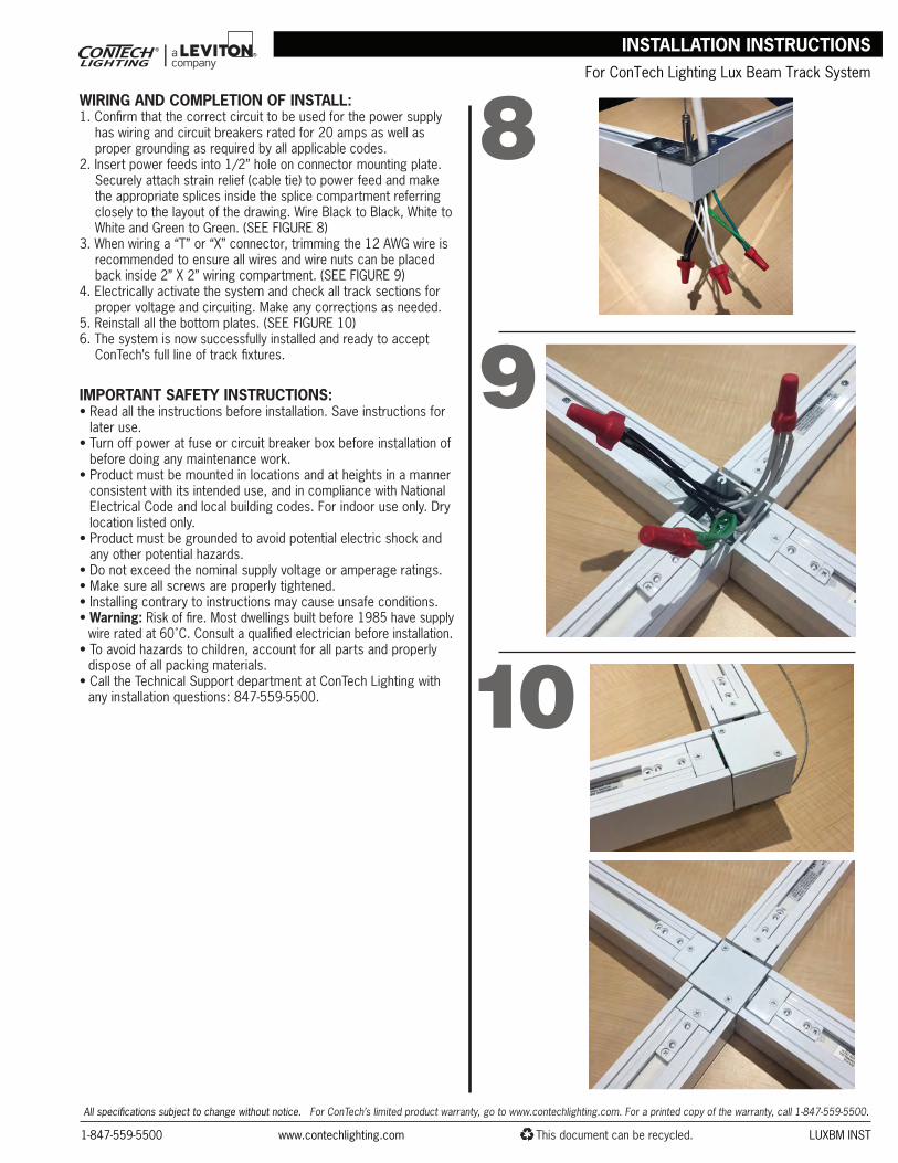
WIRING AND COMPLETION OF INSTALL:1. Confirm that the correct circuit to be used for the power supply
has wiring and circuit breakers rated for 20 amps as well as proper grounding as required by all applicable codes.
2. Insert power feeds into 1/2” hole on connector mounting plate. Securely attach strain relief (cable tie) to power feed and make the appropriate splices inside the splice compartment referring closely to the layout of the drawing. Wire Black to Black, White to White and Green to Green. (SEE FIGURE 8)
3. When wiring a “T” or “X” connector, trimming the 12 AWG wire is recommended to ensure all wires and wire nuts can be placed back inside 2” X 2” wiring compartment. (SEE FIGURE 9)
4. Electrically activate the system and check all track sections for proper voltage and circuiting. Make any corrections as needed.
5. Reinstall all the bottom plates. (SEE FIGURE 10)6. The system is now successfully installed and ready to accept
ConTech’s full line of track fixtures.
IMPORTANT SAFETY INSTRUCTIONS:• Read all the instructions before installation. Save instructions for
later use.• Turn off power at fuse or circuit breaker box before installation of
before doing any maintenance work.• Product must be mounted in locations and at heights in a manner
consistent with its intended use, and in compliance with National Electrical Code and local building codes. For indoor use only. Dry location listed only.
• Product must be grounded to avoid potential electric shock and any other potential hazards.
• Do not exceed the nominal supply voltage or amperage ratings. • Make sure all screws are properly tightened.• Installing contrary to instructions may cause unsafe conditions.• Warning: Risk of fire. Most dwellings built before 1985 have supply
wire rated at 60˚C. Consult a qualified electrician before installation.• To avoid hazards to children, account for all parts and properly
dispose of all packing materials.• Call the Technical Support department at ConTech Lighting with
any installation questions: 847-559-5500.
8
9
10
INSTALLATION INSTRUCTIONS
All specifications subject to change without notice. For ConTech’s limited product warranty, go to www.contechlighting.com. For a printed copy of the warranty, call 1-847-559-5500.