100


1New Energy Technologies #1(20) 2005
Magazine
CONTENTS• Vortex heatgenerators. Yu.S. Potapov, Russia 2• Methods of hydroelectric blow and cavitation conversion into heat and other types of energy, V. D. Dudyshev, Russia 4• Energy saving, D. Dudyshev, Russia 17• Methods of electric energy getting from natural atmospheric electricity, V. D. Dudyshev, Russia 18• New methods of extraction and use of self�energy of matter, V. D. Dudyshev, Russia 19• Revolutionary discoveries, inventions and technologies designed by Professor Dudyshev,
V.D. Dudyshev, Russia 26• News from Integrity Research Institute, Thomas Valone, USA 30• Four�dimensional resonance, A.V.Frolov, Russia 40• Multi�Rotor Homopolar Device, S. Godin and V. Roschin, Russia 45• Akoil company products, Russia 48• Environ Energy Company 52• Half�ton levitating ring is key to work, MIT, Columbia begin new energy experiment 53• Perendev Magnetic Motor update 54• Thermolevitation, S.A. Gerasimov, Russia 55• Remote influence of rotating objects on semiconductor gamma�ray detector, I.A.Melnik, Russia 58• The Bowman permanent magnet motor, Eric Vogels, Denmark 70• Possible electric propulsion Systems for flying triangles, R.Alexander, A.Whaley, UK 75• Bioelectromagnetics program 78• Energy inventions advocated by Integrity Research Institute 79• An ether�based engine as the best way of space sailing, G.P.Ivanov, Russia 81• The Evolution of Lifter Technology, T.Ventura, USA 84
Information reported in New Energy Technologies magazine is not necessary endorsed by the publisher or staff.In many cases information received cannot be verified, though we try to report the news as accurately as possible.
Scientific news on advanced propulsion systems for aerospace industry and new energy technologies
Issue #1 (20) 2005
Publisher: Faraday Lab Ltd
Editor�in�Chief Alexander V. Frolov, Scientific Advisor Kirill P. Butusov,Technical Editor Svetlana A. Schlenchak, Translator Elena N. Artemieva
Correspondence Address: 7 Lev Tolstoy Str., St�Petersburg 197376 Russia,Tel/fax: 7 (812) 380�3844, [email protected]
2005 subscription $49. All the back issues as PDF files on CD $29.Please pay online from our web site http://www.faraday.ru
Printed in Russia. Copyright © 2004�2005 by Faraday Lab Ltd.Circulation: 500 printed copies
New Energy Technologies

2New Energy Technologies, Issue #1(20) 2005
Water Vortex Heat GeneratorsWater Vortex Heat GeneratorsWater Vortex Heat GeneratorsWater Vortex Heat GeneratorsWater Vortex Heat GeneratorsYu.S. Potapov, Doctor of Technical Science, Professor, member of the Russian
Academy of Natural Sciences; V.G. Poplavskiy, Professor, Academician;I.G. Kalatchov, engineer; Ernesto-Eugenie Sanchez, student of Moscow technical
Bauman university.(095) 289-41-80
Mankind knows about vortex motion forthousands years but practical use of gas andwater vortex streams began not long ago. Oneof the tendencies is using air and gas vortexstreams for heat and cold generation in vortexRanke tubes. An incoming gas stream is dividedinto a cold stream (app. 40%) and a hot one(app. 60%) but no reliable theory of this processexists so far. As water is a low compression liquidcomparing with air, it has not been actually usedin vortex tubes and the theory of vortexprocesses in liquid has not existed. Firstattempts to generate a vortex liquid stream in atube were made in the USA by Koandaacademician in the thirties in order to find outlife origin on Earth. These experiments haveshown that the vortex stream in liquid hasconsiderable amount of energy and can generatestatic electric high stress. This data allowedsuggesting that vortex liquid stream in a closedvessel should be heated. In order to test this, avortex heatgenerator was made. It consists of acyclone, a tube, and a hydraulic brake. Thevortex heatgenerator was located in the closedvessel with an electric pump. The electric pumphas reached water height up to 80 m.
Testing of this water heating system shown thatcurrent strength of the electric engine does notchange along with water temperature rising upto + 60 С. After + 60 С�temperature is reached,current consumption volume decreases almostby two times. This effect can be easily explainedby the schedule of water viscosity according toheating temperature. Thus, with temperaturehigher than + 60 С, the heatgenerator worksthe most efficiently. Amount of electric energyconsumed by the pump’s electric engine can belowered by directing a vapor�gas mixture, whichexits the vortex heatgenerator, to enter of theelectric pump. An attempt to get the neededtemperature (+55 С) at vortex heatgenerator’sexit, however, was not successful. New vortex
heatgenerators were designed to heat water to+ 55 С and higher during one circle (Fig. 1).
In new vortex heatgenerators, a few hundredvortex streams were generated simultaneouslyproviding for more intense water heating. Inlaboratory environment, temperature of aspecial liquid has reached + 500 С allowingsteam generation using small amount of energy.
Fig. 1.
The vortex heatgenerator uses any types ofliquid as a heat carrier including antifreeze.Vortex process in liquid is used as heat energysource. It is formed between quickly rotatingrotor and stator. Rotor and stator have manysells where water is pressed and expanded. Inorder to rotate rotor, various engines are usedincluding electric and diesel ones. Duringrotor’s rotation, from 500000 to 1,500,000vortexes and passing water with temperature+15 С is heated up to + 100 С during one circle.There is no need to spend money for buildingand repair heat pipes. Cabling costs 10 times lessthan piping. Electric cable’s use costs 25 timesless comparing with expenses for maintenanceand repair of heat pipes.

3New Energy Technologies, Issue #1(20) 2005
Three�years experience of use of the vortexheatgenerator with 75�kilowatt electricengine’s power has shown that heating of 1 м2
costs less per year than heating of 1 м2 byelectric boilers. For example, a hothouse farm“Zavialovskiy” in Udmurtia set the vortexheatgenerator with a 15�kilowatt power electricengine in order to heat a dining�room sized 1910m3, ~ 636 m2. Tests were carried out in Februaryat temperature from – 5 to � 15 С. Actual electricenergy consumption during this month wasonly 3 kilowatt per hour. Pilot units wereinstalled. They are successfully working inmany farms and companies; more than thousandof new vortex heatgenerators are used.
As a rule, all customers point to environment�friendly heat energy generation, simple designand high efficiency of the new method of heatgeneration in comparison with traditionalheating methods. The vortex heatgenerator usessynergy effect consisting of three knownphysical processes. Water is heated by friction,cavitation and combination of water moleculesin clusters during rotation. Each process takenseparately does not give the needed effect andwater heating speed. This heating method is ahigh molecular technology.
Priority of Russia is confirmed by patents.
Applications of the new heating method:
� heat and electric energy generation;� medical purposes;� spacecraft engines;� food industry;� steam production.
References
1. Yu.S. Potapov. Patent of the RussianFederation # 2045715 “Heatgenerator andLiquid Heating Device”. Invention priorityfrom April 26, 1993. Registered in StateInventions’ List on October 10, 1995.2. Yu.S. Potapov etc. Patent of the RussianFederation # 2165054 “Heat GenerationMethod”. Invention priority from June 16,2000. Registered in State Inventions’ List onApril 10, 2001.3. Yu.S. Potapov etc. Patent of Ukraine # 47535
“Heat generation method”. Invention priorityfrom May 18, 2000. Registered in Bul. #7 fromJuly 15, 2002.4. Yu.S. Potapov. Patent application of theRussian Federation # 2003133221 “Method andDevice for Heat Energy Generation”. Inventionpriority from November 14, 20035. Yu.S. Potapov etc. Application РСТ W001/96793 A1 from December 20, 2002 “Method ofHeat Generation”.6. Yu.S. Potapov etc. Patent of Ukraine # 38030“Method of Reactive Traction Generation forSpacecrafts”. Registered in Bul. #4 from May15, 2001.7. Yu.S. Potapov, S.Yu. Potapov. “Energy fromWater and Air for Agriculture and Industry”.K. 1999, 87 p.8. Yu.S. Potapov, L.P. Fominskiy. “VortexEnergy Systems and Cold Fusion According toRotation Theory”. K. 2000, 387 p.9. Yu.S. Potapov, S.Yu. Potapov, L.P. Fominskiy.“Rotation Enery”. K. 2001, 383 p.10. V.A. Atsjukovskiy. “Energy Around Us”. M.Energoatomizdat. 2002, 93 p.
Yuri S. Potapov

4New Energy Technologies, Issue #1(20) 2005
METHODS OF HYDROELECTRIC BLOW ANDMETHODS OF HYDROELECTRIC BLOW ANDMETHODS OF HYDROELECTRIC BLOW ANDMETHODS OF HYDROELECTRIC BLOW ANDMETHODS OF HYDROELECTRIC BLOW ANDCAVITATION CONVERSION INTO HEATCAVITATION CONVERSION INTO HEATCAVITATION CONVERSION INTO HEATCAVITATION CONVERSION INTO HEATCAVITATION CONVERSION INTO HEAT
AND OTHER TYPES OF ENERGYAND OTHER TYPES OF ENERGYAND OTHER TYPES OF ENERGYAND OTHER TYPES OF ENERGYAND OTHER TYPES OF ENERGY
V. D. Dudyshev, Samara, RussiaV. D. Dudyshev, Samara, RussiaV. D. Dudyshev, Samara, RussiaV. D. Dudyshev, Samara, RussiaV. D. Dudyshev, Samara, [email protected]@[email protected]@[email protected]
http://www.valery12.narod.ru/index1.htmhttp://www.valery12.narod.ru/index1.htmhttp://www.valery12.narod.ru/index1.htmhttp://www.valery12.narod.ru/index1.htmhttp://www.valery12.narod.ru/index1.htm
This article is dedicated to analysis andsubstantiation of a new available trend of powerengineering based on a concept which allowsgenerating cheap heat, mechanical and electricenergy using hydroelectric Yutkin effect andcavitation. New original effective no fuelelectrohydrodynamic turbines, motors, pumps,heat�generators and electrogenerators usingminimal quantity of electric energy are presented.They use self�energy of liquids, air and energyof environment. Using these devices will lead toabrupt reduction of cost of heat, mechanical andelectric energy generating technologies. This willallow improving and simplifying the existingheat�power devices and motors for all types oftransport. The technologies are patented.
HOW CAN WE GET CHEAP HEAT?
Cavitation effect in liquid is used for heatenergy generation [3�6]. There are well knowncavitation, vortex, rotor etc. heat generators byPotapov, Larionov, Petrakov etc. They are basedon using abnormal heat energy generationduring cavitation in liquid. However, they havea powerful electric motor which is adisadvantage. Meanwhile, such cavitationheaters based on hydrodynamic method ofliquid heating are widely used because they lackfor many essential defects of standard electricheaters. Particularly, they can heat almost allliquids while electric heaters have high waterquality requirements. Efficiency of cavitationgenerators is high because electric energy lossesof pump (efficiency is ~70 %) are used forhydraulic fluid heating. According to the
researchers, there are cavitation generatorshaving exergy coefficient more than 1 [3�6].
A design of a no fuel device for heat energygeneration using cavitation effect is simple. Thedevice (Fig. 1) consists of electromotor, pump,piping, which forms closed contour of heat�supply, cavitator (Laval nozzle), adding device.
Fig. 1
Working principle of this machine is simple.Water flow (or other liquid) runs under pressurethrough cavitator’s tube, which has a canal withvariable cross�section. Running throughcavitator, the flow breaks, bursts, forms fastsplitting cavities (gas, air bubbles). This iscavitation.
According to numerous experiments, theabnormal heat energy is generated during theprocess of bubble bursting. The more liquid

5New Energy Technologies, Issue #1(20) 2005
pressure is at the cavitator’s entrance, thestronger cavitation is, the more heat is released,and the more effective heatgenerator.
Cavitation effect in the tube can be producedin different ways though the better one is anadvanced Laval nozzle.
The point is that, unlike other types ofcavitators, such nozzle never get blind, eventhere are mechanical particles in the flow. Inorder to heat the liquid for cavitation, anelectric pump with power corresponding to heatgenerated is necessary.
Another essential disadvantage of these trulyprogressive heat energy cavitation devices ispump rotor, which reduces reliability andefficiency factor of the device and also causesdifficulties during exploitation andmaintenance, particularly, during sealing�in ofthe construction.
Complete improvement of cavitation heatgenerators
In order to implement a technological gap inthis industry, it is necessary to eliminate thebulky and gluttonous electric motor of thepump and reduce considerable electric energylosses in known cavitation heatgenerators(CHG).
So, there are some important questions. Howto create pressure and cavitation of the liquidwithout electric pump; how to improvecavitation and heat generation; how to createan autonomous heatgenerator which doesn’t useexternal energy?
A brief answer is that it is necessary to useskillfully and simultaneously Yutkin effect andcavitation one. We will describe the workingprinciple and design of these cavitationgenerators of new generation below. First, wehave to remember what electrodynamic Yutkineffect is.
Physical characteristics of hydroelectricYutkin effect
This abnormal effect was discovered by aRussian engineer Yutkin L.A. [1]
Hydroelectric blow effect (HEB) takes place inliquids, for example, in water, during electricdischarge. HEB is an electric explosion in liquidaccompanied by almost immediate energygeneration at the given point [1]. Quantity andspeed of kinetic and heat energy generated inthe electric discharge zone depends on manythings including characteristics of electricdischarge and liquid. Compression wave, whichappears during intense liquid’s evaporation inthe discharge zone and steam expansion inelectric�arc space, can be caused by both singlestrong pulse electric discharges betweenelectrodes placed in liquid and a consistentseries of impulses. Electric charge power can beincreased due to electric energy store.
KNOWN APPLICATIONS OF HEEYUTKIN EFFECT
This effect is widely adopted in industry [1].
The hydroelectric pulse technology (HEP),based on the effect, is one of the most up�to�date industrial processes. It allows using electricenergy for material processing byhydrodynamic disturbance. Hydroelectric blowis used for cold metal processing, rock failure,intensification of chemical change etc.
Unique possibilities of HEB Yutkin effectapplication in energy engineering
This effect of abnormal energy generation fromliquid during electric discharge, however, hasvarious latent opportunities and newunexpected fields of use due to its multi�purposefulness and abnormal energy system.
It can be used, for example, by heat�powerengineering for noncontact generation of cheapheat energy, for designing of new economical nofuel motor for all types of transport. It will bedescribed later.
Methods of HEB energy conversion intoother types of energy
This effect can be implemented by the followingmeasures:
а) no fuel cheap heat energy generation

6New Energy Technologies, Issue #1(20) 2005
United usage of HEB effect and cavitation willallow generating cheap heat energy frominternal liquid energy. The simplest design andworking principles of the cavitation HEB�heatgenerator are shown on Fig. 2.
The device was tested on a model in laboratoryconditions.
b) no fuel cheap mechanical energy generation
Energy of liquid HEB in a processing chambercan be easily converted into mechanical energyof liquid motion, for instance, in economical nofuel electric�discharge turbine, pumps and otherup�to�date rotors (Fig. 3,4,5).
c) no fuel cheap energy generation
First, it can be done by means of an electric pulsewater pipe and electric generator placed at itsaxle. Second, we can generate steam by HEB�generator and then convert its heat energy by astandard turbogenerator.
There are other ways of electric energygeneration. It can be done, for instance, bydirect electric hydrodynamic method providedwith pulse electric charge of neutral liquids orby magnetic hydrodynamic method providedwith sufficiently electroconductive liquid.
d) simultaneous no fuel cheap generation ofheat, mechanical and electrical energy
This requires a combination of the methods anddevices listed above.
e) liquids’ burning and steam dissociation; usingHEB method, steam transformation into fuelhydrogen�containing gas, which is then burned
h) cheap effective waste treatment andsimultaneous fuel gas generation
Effective waste treatment can be carried outusing this original electric hydrosystem. Due tocavitation, particles split in liquid flow andliquid is decontaminated. Adding vortexseparator, it is possible to remove and convertcontaminations, for example, to movehydrocarbon from water to fuel gas. Let’s lookat these conversion methods using HEB effect.
Methods to control power, pressure andstrength of electrohydrodynamic blow andusage of electrohydrodynamic converters
How can we effectively control characteristicsof electrohydrodynamic blow and processes ofconversion into other energy types? On ouropinion, it can be easily done [7].
Electrohydrodynamic blow’s power, intensityand frequency control as well as liquid pressureon labour body can be implemented by changingelectric discharge’s characteristics, for example,amplitude and frequency of electric impulses[2]. According to this method, high�voltagedischarges of controlled power take place inliquid, in the processing chamber. Hydraulicsteam pressures forming in the discharge zonepass these blows on the labour body located inthe processing chamber. The labour body canbe a water turbine.
Thus, it is possible to control power,frequency and length of labour body, forinstance, electrohydrodynamic pump’s ormotor’s plunger, or control rotation speedand effective capacity of hydroelectricturbine by changing frequency and power ofhigh voltage electric discharges in liquid.
Sometimes a moment of electric discharge’sbeginning is synchronized with the labourbody’s position. This synchronization ofpressure impulses can be used in water�electricdisplacement pump and motors. Frequency andpower of alternate�reciprocal motion made byplunger is carried out by controlling frequencyand power of alternating electro hydraulicblows on either side of the plunger [2]. Thesynchronization, however, isn’t necessary forhydroelectric turbine’s design (Fig. 4).
NONCONTACT CAVITATION HEATGENERATORS (CHG)
Let’s look at some of the simplest types of suchgenerators (Fig 2,3).
Constructions of electric blow cavitationheatgenerators. (Fig. 2,3)
Using a cheap noncontactelectrohydrodynamic pump based on Yutkin

7New Energy Technologies, Issue #1(20) 2005
effect allows complete improvement andsimplifying cavitation heatgenerator because itdoesn’t include electric motor al all. Thus newsimplest noncontact effective heatgeneratorusing fixed and repeated short�term electricdischarge taken place in liquid is shown onFig.2.
Fig. 2. Flow block of noncontact CHG
1 � waterproof capacity with liquid 2; 3 � air cavity;4,5 � electrodes; 6,7 � electric insulator; 8,9 � cavitators;10 � store electric capacity; 11 � pressure transformer;
12 � primary electric energy supply; 13 � system of electricdischarges’ frequency and amplitude control; 14 � temperature
and pressure sensing device; 15 � electric discharge zone;16 � zone of liquid evaporation
This simple device consists of only three mainsimple noncontact elements, which are acapacity with liquid (with an air cavity), anelectric discharge switch (a couple of electrodes4,5 injected in liquid) and a cavitator, forexample, a simple perforated board or closedperforated surfaces 8,9 of different diametersand faces forming concentric Laval nozzles.Cavitators are located in the capacity 1. Agenerator of strong electric impulses 11,supplied with power by a primary electricenergy supply, is joined to the electrodes 4, 5through an electric energy store 10. Amplitudeand frequency of voltage impulses is controlledby the control system 13. At the entrance, theimpulse generator 12 placed temperature andpressure sensing devices 14.
Working principles and process of heatgeneration carried out by this CHG is the
following. Liquid is heated due to cavitationcaused by electric discharges and followinghydroelectric blows. Due to repeating electricdischarges, the plasmic zone 15 forms betweentwo electrodes and then, practicallymomentarily, a high pressure gas�vapor cavityforms, which has much more energy than energyused for discharges. Vapor pressure energy andchemical energy of H
2 power gas, generated
during process of electric lightning andelectrohydrodynamic blow, cause high pressurewaves in liquid and intensive heating bycavitation and H
2 vapor gas burning. As each
impulse electric discharge leads to a new H2
vapor cavity formation, H2 burns, a new blow
and a new wave follows. As this wave moves,strong cavitation takes place on perforatedcavitators 8, 9. Due to intense cavitationbubbles’ splitting and H
2 vapor gas burning,
considerable amount of heat is generated inliquid. Cavitation is more intense in this methodthan in rotor and vortex heat generators whilethe quantity of electric energy spent is the same.The heat generator controls heat generationintensity by frequency, amplitude and length ofvoltage impulses. The generator can also runcontinuously. With use of this heating method,energy effectiveness and heat generationintensity depends both on electric discharges’characteristics, liquid’s characteristics and adesign of the impulse heat generator [2].
Electric�blow cavitation heatgenerator withrotating electric arch (Fig. 3)
We suggest a more efficient vortexelectrohydrodynamic magnetic heatgeneratorwith rotating electric arc 9 in liquid 2, whichgenerates electrohydrodynamic air�blast due tocavitation and intense heat energy. This originalheat generator’s design is shown on Fig. 3. Incase one electrode or two electrodes 1, 3 are ring(cylindrical), direct voltage is led to themthrough nonmagnetic walls of a cylindricalelectric�discharge chamber 1. A strong ring ordisc constant magnet 7, located across the ringelectrode’s surface, generates external magneticfield, which allows rotating the electric arc withhigh speed, up to acoustic speed and higher.Using this method, electrohydrodynamic blowcan be intensified causing constant air�blastgenerating and cavitation taken place incavitators 8, which adjoin perforation of the

8New Energy Technologies, Issue #1(20) 2005
internal walls 1, 3. This will allow simplifyingthe heat generator construction and gettingintense cavitation during air�blast and electricarch rotation. As a result of electric arc rotation,the liquid will rotate itself. That will allowimproving heat generation due to bothelectrohydrodynamic air�blast of liquid andintense cavitation during liquid’s contact withthe perforated wall 3. In case the electricdischarge chamber has a cone construction, itis possible to get a combinedelectrohydrodynamic reversionary pump�heatgenerator. In order to backspace a directionof the liquid’s rotation, backspacing of voltage
sign of electrodes 1, 3 should be implementedby voltage sign switching from the electricenergy source.
SIMPLESTELECTROHYDROCAVITATION
HEATGENERATOR
Combining electrohydrodynamic blow effectand cavitation one, it is quite possible to createa simple 3�5 kilowatt�heatgenerator using astandard car electric ignition and 200�300 wattenergy consumption from a storage battery. Thegenerator is a small electrohydrodynamic�blowdevice made according to schemes 2, 3. Itconsists of a cylindrical capacity with water,standard car ignition plugs screwed into thebody and electrically connected to a usual carelectric ignition system, a storage battery, a carcoil and an electrolytic capacitor as energystorage, internal cavitation devices, for example,perforated shields, which present coaxial metalcylinders with surfaces perforated by holes withdifferent diameters. Such combination ofelectrohydraulic pump and cavitation allowselimination of the electric pump motor andimproving efficiency and reliability of theheatgenerator.
BIPHASE EHD HEATGENERATOR(Fig. 4)
In order to improve heat generation efficiencyusing EHD method in combination withcavitation effect, we suggest various types ofcascade cavitation�electrohydroheatingdevices. A biphase EHD�heatgenerator consistsof two EHD�pumps 1, 2 containing impactchambers 3, 4 with cones 32�35 and perforatedcavitators 28�31, a few EHD�accelerators(helix�like swirl blades 9�11) connected withcones 32�35. Tubes 27 connect junctions of thisheat�main forming a closed system. Radiatorsare not shown on Fig. 3 but they are originaltoo, connected with additional cavitators ofLaval nozzle type. This EHD heatgenerator canalso use the rotating electric arc, in case it ismodernized according to the scheme (Fig. 3).
The construction is described in details underthe figure.
Fig. 3 Vortex heatgenerator
a) view from above1 � body � first ring electrode; 2 � liquid (water); 3 � internal
ring electrode (perforated); 4,5 � leading�in electrodes;6 � reversing energy source with electric voltage controller;
7 � constant magnet; 8 � cavitators – perforation on ringelectrodes 1,3; 9 � lead�in nipple; 10 � lead�out nipple;
11 � electric arc; 12 � lead�out nozzle; N�S � magnetic poles;dotted line – magnetic flux and rotation path of electric arc
b) front view

9New Energy Technologies, Issue #1(20) 2005
There are simpler economical methods of cheapheat generation, for instance, ones based on acombination of cavitation effect andgravitation. They are described below.
SIMPLEST CAVITATION�GRAVITATION
HEATHYDROGENERATORS
Having an initial liquid flow, it is easier to getheat.
Fig. 4.
1,2 – electrohydrodynamic pumps; 3,4 – impact chambers;5,6 � electrodes; 7,8 – electric insulators; 9�12 � helix�like swirlblades with tangential admissions; 13,14 – high pressure zones
at electric discharge area; 15,16 — clacks; 17 – capacity withliquid; 18 – high controlled voltage block (HCVB);
19 – HCVB controlling system (using voltage frequency andamplitude); 20,21 – voltage changers; 22,23 – inductive
winding; 24,25 � electric energy demand; 26 – primary energysource; 27� tubes; 28�31 � built�in cavitators;
32�35 – cone tubes;
In order to do this, it is only necessary to usesimultaneously gravitation and cavitation. Thisallows generation of cheap electric energy by,for example, ordinary hydroelectric power station.
Cavitation heat HEP stations
Dam HEP stations use a strong water flowgiven by Nature due to gravitation force. Thestream is practically free and constant. We onlyhave to use cavitators. Up to 50% electric poweris spent on heating of nearby buildings,
especially in winter. In case a part of fallingwater will be transformed by cavitation nozzles,we can get directly cavitation heat at HEPstations because it is possible to get 1.5 / 0.84 /0.6 = 2.8 kilojoules of heat for each kilo joule ofthe falling stream’s kinetic energy!
Taking into account that cavitator is cheaperthan turbogenerator, it becomes clear that suchheatgenerators are very profitable.
Cavitation�streammicroheatelectrogenerator
The mentioned above principles of cavitationand gravitation effects combination allows easyconstruction of a simple cavitation micro heatand power plant even in private life. It ispossible, for example, to pass an almost free(especially in case there is no waterconsumption meter) cold water stream underpressure through cavitator, for example,cavitation Laval nozzle and through microturbine. It will allow generation of heat andelectric energy using a micro HEP station. Theheated liquid will then circulate in a closedcircuit under the influence of gravitation andconvection forces. In case there are no initialliquid stream, it is possible to get it almost freeusing electrohydrodynamic Dudyshev effect[7]. This stream of dielectric liquid can begenerated using minimal quantity of electricenergy due to explosive electrons’ injection inliquid by our electrohydraulic Coulomb method[7]. In case electrohydrodynamic Dudysheveffect is used for cheap heat and electric energygeneration, dams and water taps are notrequired. It is only necessary to place cavitatorand micro hydro turbine with electrogeneratoron the path to the artificial Coulomb stream.Thus, a closed cycle of liquid’s motion under theinfluence of gravitation force is made. Acompletely autonomous source of cheap heatand electric energy is ready to work.
Its available heat and electrical powers aredetermined during designing and production byconstruction operation characteristics.
Due to cavitation, liquid begins to heat. Thiswarm water can be used in private life forwashing, bath, during summer absence of hotwater etc. Such mini heat energy device can

10New Energy Technologies, Issue #1(20) 2005
have dozens kilowatt of heat power. That’s whyit can be used even for autonomous heat andelectric energy supply of a small cottage.
NO FUEL CHEAP ELECTRIC MOTORS.YUTKIN EFFECT AND DIRECT
METHIOD OF GENERATION OFMECHANICAL ENERGY AND LIQUID’SREACTIVE TRACTION WITHOUT ANY
FUEL
Electrohydrodynamic Yutkin effect opens newhorizons for designing various super economicalno fuel motors using water. They can be used astransport motors of new generation.
Let’s examine direct method ofelectrohydrodynamic blow transformation intopressure and kinetic energy of alternate/reciprocal piston’s motion or autonomouselectrohydroturbines’ rotation.
Electric�hydro�blow piston motor�pumphttp://www.valery12.narod.ru/index1.htm
Electrihydrodynamic blow effect can besuccessfully used for no fuel electro hydromotors, for transport and no engine pumps.We’ll explain this by the example of the EHDmotor (Fig. 5).
Design of this piston electrohydrodynamicmotor is shown on Figure 5. Its elements arelisted above. This is a rather simple device forgeneration of kinetic rotation energy by pistons’translation. It is based on using potential energyof electric field and effect of blowelectrohydrodynamic pressure in liquid (Yutkineffect). A main upper processing EHD�chamber1 is filled with liquid 9, for example, water, andhas an insulated electrode 11. An electricdischarge takes place through liquid to the innersurface of the chamber’s body due to a voltageimpulse fed from a controlled high voltage block(CHVB), which is supplied from voltage source(a storage battery) and electric condenser 10.As a result, a pressure jump in liquid (EHDblow) occurs. It is passed to a first smallstrengthened piston 2. Then,electrohydrodynamic pressure in liquid ispassed through the piston 2 and a shockabsorber 3�air reducer to a main processing
piston 4. The piston 4 passes its kinetic energythrough a connecting rod 5 and a crankshaft 6to a motor drive for rotation of economical nofuel electrohydromobile’s wheels. After rotationof the crankshaft 6, pistons 2, 4 return to thestarting position and the process repeats. Theno fuel EHD motor can be diphase as well asmultiphase, for example, a four�phase type ofpiston hydromotor. In this case, it containsseveral electric discharge chambers. You canlook at an animated image of such motor’s workon http://www.valery12.narod.ru/index1.htm.
Frequency of pistons’ motion is controlled byfrequency of high voltage impulses fed by CHVblock while power of hydromotor and shaftpower is controlled by strength of EHD blowby controlling current strength and longelectric discharge in liquid from the block orchanging of electric capacity of the condenserC (Fig. 3). The same device can be used as hydropump for transmission of liquids by the piston2 through cavity 3 while the piston 4 is fixed.Input�output channels are not shown. In casethe inductive winding is placed outside thenonmagnetic body 1 and magnets on the rod oron the piston 4, the device also presents anoriginal magnetic�linear oscillator (it is notshown on Fig. 3). This motor can be used as apump or a heater, in case the pump circuit isclosed. Efficiency of this motor was alreadytested experimentally. In order to produce a pre�production model, thorough research is needed.
Fig. 5. Electrohydrodynamic motor

11New Energy Technologies, Issue #1(20) 2005
Economical turboprop EHD engines andcombined turbine EHD motor�generators
by Dudyshev (Fig. 6)
Using Yutkin effect, it is possible to design nofuel vortex or straight flow jet propeller�pumpon basis of a new electrohydraulic turbine. Wesuggest that, first, EHD�blow energy istransformed into cycle changing of liquidpressure in the cylinder 1, in order to rotate anelectrowater pump, then, generate a constant(pulse) unidirectional speed liquid flow througha hollow tube located under the bottom of thisunusual water transport. Correspondingly, it ispossible to design a device for transmission ofliquids on basis of this original pump. Theturbine rotates by alternate electric dischargesfrom electrodes located on waterturbine blades.They cause electrohydraulic cyclic blows ofliquid directed at an original electrohydraulicDudyshev propeller. Design types of theeconomical electrohydrodynamic watermotorare described below. Such method is moreuniversal, having more wide scope: along withelectro impulse turboprop flow in liquid, it ispossible to generate electric energy combininga turbine and an electric machine. This originaldevice can be also used as a pump.
Fig . 6. Combined electrohydroturbine – heatgenerator
Electrohydraulic turbine (Fig. 6) consists of ahollow or waterproof strengthened cylinder 1,a waterturbine 2 (rotating trajectory of the itsblades 3,4,5 is shown by dotted line) with a shaft
6 and a rotational axis 7. Fixed reverse blades�repellers 8,9,10 etc. are located on the innersurface of the processing cylinder (there are 6blades�repellers on Fig. 6). They are electricallyattached to a high voltage block of controlledvoltage 14 by electric insulators 11�13. Theblock 14 is attached to an autonomous energysource (a storage battery) 15 and an electricstore – condenser C, while it is connected to acontrolling device 16 by the control circuit ofthe block 12.
Sensors can be attached to the controllingdevice 16, for example, a sensor 17 of the turbinerotation frequency or liquid temperature. Theshaft 6 is electrically earthed. Turbine blades3,4,5 and repellers’ blades 8�10 have a runningclearance at convergence points, which allowsthe turbine rotates feely.
Processing principles of the device are based ongenerating of cycling waves of liquid pressurecaused by EHD�effect directed at the turbineblades. Due to high voltage electric potentialfed on motionless repellers’�blades 8�10, anelectric discharge occurs in liquid, in extremepositions between the blades.Electrohydrodynamic blow is transferred to theturbine blades and makes the turbine rotate.Pressure and effective capacity of thiseconomical electric discharge turbine dependson power and length of the discharge. In casethe hollow cylindrical chamber is used, thedevice is a water propeller�pump of newgeneration. It can be used at water transport andfor transmission of liquids in trunk pipelines.The device can also be an economical cavitationheatgenerator, due to cavitators 18 fastened tothe cylinder 1 by strong perforated diaphragms(they are shown on Fig. 5 at cross�section of theturbine by small squares). Top speed of theturbine is conditioned by design and liquidcharacteristics.
TECHNOLOGICAL PROPERTIES OFTHE DEVICE
Certainly, this electric discharge hydro turbineshould be strengthened; all blades should haveanti�corrosion protection, because they must bereliable and long�lived during electro chemicalmetal mass transfer. Material of the blades can

12New Energy Technologies, Issue #1(20) 2005
be protected by rational use of alternating highvoltage with frequency, which considerablyexceeds rotation frequency of the turbine. Inorder to maintain top rotation speed matchingwith operating speed of standardelectrogenerators, magnetic bearers andmagnetic reducers should be used [8]. The sameenergy efficient process is a basis for designingof a no fuel jet turbine engine, which can be usedin aviation. Due to cyclic electro gas dynamicair�blasts in a hollow chamber, effective rotationof a high speed air turbine can be obtained usingheat and molecular air expansion. The enginecan be used in atmosphere as well as in aviationor space propulsion engines of low and mediumspeed.
Straight flow no fuel EHD Dudyshev jets
Yutkin effect can be used for straight flownoncontact no fuel EHD jets using straightliquid flow without any turbine. Such electrohydro jets are available for water�jet propellersof new generation used in water or air transportas well as pumps (Fig. 7).
Fig. 7. Straight flow water jet
1 � hollow body; 2 � straight flow combined electric dischargechamber; 3 � lead�in nozzle; 4 � lead�out cone nozzle
(cavitator); 5 � central axial electrode; 6 � electrical insulator;7 � magnetic ring electrode; 8 � reversible voltage transformer;9 � autonomous energy source; 10 � controlling system of the
block 8; 11 � constant ring magnet; 12 � rotating arc;13 � movable diaphragms; 14 � store plates; 15 � electrical load;
16 � reactive liquid flow; 17 � magnetic flux; V � speed of the
vessel in liquid; С – store electric condenser
The simplest type of this jet is shown on Fig. 7.It consists of a hollow body 1, which contains a
cone hollow chamber with nozzles 3,4 and anelectric discharge chamber 2 containing acentral axial electrode 5 injected through anelectric insulator 6 and a second ring electrode7.
A constant ring magnet 11 is located outsidethe electric discharge chamber. The centreelectrode 5 is electrically connected with areverse transformer of repeated stress 8.Characteristics of electric arc can be controlledby a controlling device 10 attached to a block8, which works using an autonomous energysource 9. It should be mentioned that themagnet 11 is oriented by its poles according tothe ring electrode 7. Thus, its flux isperpendicular to the electric arc 12. Due to this,effect of electric arc rotation takes place at theperimeter of the ring electrode 7. A magneticfield for the electric arc’s rotation can begenerated in the plane, which is perpendicularto the ring electrode’s plane, by a specialsolenoid in a nonmagnetic waterproof body (itis not shown on Fig. 7). The principle of theelectric arc’s rotation was explained earlier bythe example of vortex EHD heatgenerator andshown on Fig. 3. The device contains movablediaphragms 13, in order to generate repulse andcontrol the liquid flow, and store electrodes 14attached to an autonomous electrical load 15.Let’s discuss how this jet works.
Principle of the jet’s processing. After voltageis fed by the block 8 to the electrodes 5 and 7,the electric arc 12 appears between them in thechamber 2. Due to power electromagneticinfluence of the electric arch with the flux 17,the arc begins to rotate around the ringelectrode 7 with acoustic speed. Its directionand rotation speed is controlled by thecontroller 8. At the same time, due to constantEHD effect, a strong pressure wave arisesaround the ring 7. Due to the cone design of thebody 1 and presence of diaphragms 13, theelectro hydro blow pressure wave in liquidgenerates a straight flow 16. Actually, thereactive liquid flow appears in the cone nozzle4 after a constant electric discharge. Duringrotation of the electric arc 11, a strong constantair�blast appears in the direction, which isperpendicular to the rotation surface. Thishappens due to electrohydraulic blow effect inliquid and liquid’s mechanical reaction, which

13New Energy Technologies, Issue #1(20) 2005
influences the body 1. As a result, the vesselmoves using a reactive liquid flow 16 at speedV. According to the third Newton's law, the air�blast deflects from the repellers 13 and the bodyof the cone nozzle. This improves the reactivepropulsion. Thus, EHD�blow energy can beright away transformed into the reactive liquidflow, i.e. no fuel electric water jet propeller ornew noncontact EHD�pump can be designed.Maximal reactive propulsion of vortex liquidstream in the cone lead�out nozzle is the mosteffective in case the electric arc rotates in theconstant magnetic field under the influence ofAmpere’s force. In case this device is used in seawater, it also can generate electric energy usingmagnetic hydrodynamic generator. The deviceis supplemented with a system of charge storeelectrodes 14 located at nozzles’ sides. Part ofthis energy is used for the autonomous electricload 15 or recharging of the autonomous source9. As a result, the device can work completelyautonomously.
Other designs of the straight flow EHD motorcombined with cavitators are possible. Suchcavitator is shown in squares on Pos. 4, Fig. 7.The suggested types of the original no fuelstraight flow reactive EHD�motor use smallquantity of energy for hydraulic pressuregeneration. Due to this, they can move watertransport, for example, a ship, without any fuel.They can be also used as noncontact pumps inwater and oil pipes.
The same economical type of reactivemovement, due to electro gas dynamical burstand air expansion, is possible in atmosphereusing the new type of motor. It can be used inaviation as well as for space propulsion enginesof second and third stages, low and mediumpower used for orbiting sputniks.
USING YUTKING EFFECT FORSIMULTENEOUS GENERATION OFKINETIC ENERGY OF ROTATION,
HEAT AND ELECTRIC ENERGY
Unique EHD effect combined with the othereffects (cavitation, electromagnetic induction,vortex effects etc.) can be used in any kind ofautonomous energy system, for instance, forrotation of high�speed turbine with electro
generator (Fig. 8) or in a combined hydro turboelectro generator with constant magnets (Fig.9, 10). Each design has its own merits anddemerits, but they all use electric dischargechambers and air�blasts, i.e. EHD Yutkin effect.In order to generate heat energy, cavitators –perforated plates are used. All the designs areimportant steps in searching the optimal systemdesign of economical heat generator usingYutkin effect. All design elements are describedbelow the figures. As it was mentioned above,in case the electrohydraulic turbine and thestandard electro generator are combined at oneshaft, a unique possibility to generatesimultaneously mechanical, electric and heatenergy appears. This design allows generationof electric and heat energy with better efficiencythan it was in the previous methods [3, 6], dueto removal of the bulk electro motor of thepump. In this case, the electric discharge turbineacts as pump. Main advantages of this newmethod of heat and electric energy productionbased on EHD�device are autonomous work,ecological cleanness, safety, simplicity andefficiency. Design of the combined magnetic
Fig. 8. Соmbined cavitation heat turbo electro generator
1 – EHD pump; 2 – electric discharge chamber of EHD pump;3,4 � cones; 5,6 – electrodes (one of them can be ring);
7,8 – electric insulators; 9,10 – reactive turbines;11,12 – vortex helixes with tangential lead�ins; 13 – zone of
electric arc and high pressure vapor; 15�17 � pipes; 18 – blockof high controlled voltage (BHCV); 19 – controlling system
for BHCV (using voltage frequency and amplitude);20 – primary electric energy source (storage battery);
21�23 – electro mechanical generators; 24 – electric load atlead�outs of electric generators; 25 – liquid temperaturesensor; 26,27 � cavitators (perforated discs); 28 – axle of
turbine and generator (arrow shows direction of rotation ofaxle); 29 – central water helix with two entrances; 30 – water
turbine; 31 – central cavitator

14New Energy Technologies, Issue #1(20) 2005
electro hydro dynamic turbo generator (Fig. 8)includes vortex helix�like elements, whichintensify cavitation processes and heatgeneration in liquid allowing using standardelectro generators. A common advantage of thedesigns is that they have separate electricdischarge chambers 18 moved from a hydroturbine chamber. This improves their reliabilityand durability.
In a device on Figure 8, the electric dischargechamber 2 of the EHD pump 1 is located in aspecial strengthened cylinder and connected bycones with two vortex helixes 11, 12.
In a combined device on Figure 9, the electricdischarge chamber of the EHD pump 18 islocated in a tangential arm of the helix 1.
Only in a design shown on Figure 10, theelectric discharge chamber of the EHD pumpis combined with a cavity 2 of the hydro turbine.In this case, the inner surface of the cylinder 1is the first electrode while the second one isstrengthened turbine blades 3, 4. As a result, theelectric arc rotates with the turbine blades,which allows reducing corrosion deteriorationof the electrodes and getting maximal cavitationand heat generation in liquid in the tree designsof the device (Fig. 8�10).
This is the simplest and high�speed electricdischarge turbine, which allows generation ofmaximal power using the device of minimal size.
HOW TO BURN A NONFLAMMABLEFLUID, FOR EXAMPLE, WATER AND
ITS VAPOR?ELECTROHYDRAULIC BURST OF
WATER VAPORUSED AS FUEL IN BOILERS ANDMOTORS OF NEW GENERATION
The idea of using EHD blow in liquid and thentransforming the generated self�energy intoother types of energy can be improved and usedfor phases of liquid, for instance, for pulse EHDdissociation of water vapor into H
2 fuel gas. This
is described below.
The method suggested is undoubtedly available.It allows generation of not merely pressure on
water motor’s piston, but also electric energyfrom water. We suggest using liquid vapor asfuel for motors of new generation. Heat andelectric energy and overpressure caused byelectric heat burst of water vapor (mist) isfantastic but real!
It is known that fine air slurry of motes or cottonparticles, having certain concentration, tend toburst in the presence of spark.
The reason is that speed chain reactions ofionization and burning occur and quicklydevelop. A small electric spark can cause a burst.Effect of fine aerosol’s burst is already used butnot for good purposes, although this effect canbe used effectively, for example, in no fuelmotors of new generation.
Technology of vapor transformation intoburning H
2�fuel
Method of vapor transformation into H2 fuel
represents electric arc dissociation of vapor intoН
2 and О
2 using EHD�effect. It allows
generation of heat, electrical and mechanicalenergy from abnormal energy of electric arcburst of water vapor. The effect can be used inmy original electric�burst steamer working onwater (according to EHD design on Fig. 4). Doyou believe this? If no, learn the suggestedtechnology.
Steam burning is carried out using electricdischarge dissociation. During this process,local volume of cheap Н
2 is generated from
steam and right away burned. Н2 contains gas
fuel. So, I suggest transforming heat losses ofthe standard petrol engine into yield, i.e.evaporating water and then burning steam.
The following simple operations should becarried out:
а) due to heating and evaporating by dischargemanifold, water steam (or water�fuel) of highpressure is obtained;
b) this overheated steam is given a little at atime in the special electric discharge burstchamber, for instance, in the combustionchamber of the ordinary internal�combustionengine;
15New Energy Technologies, Issue #1(20) 2005
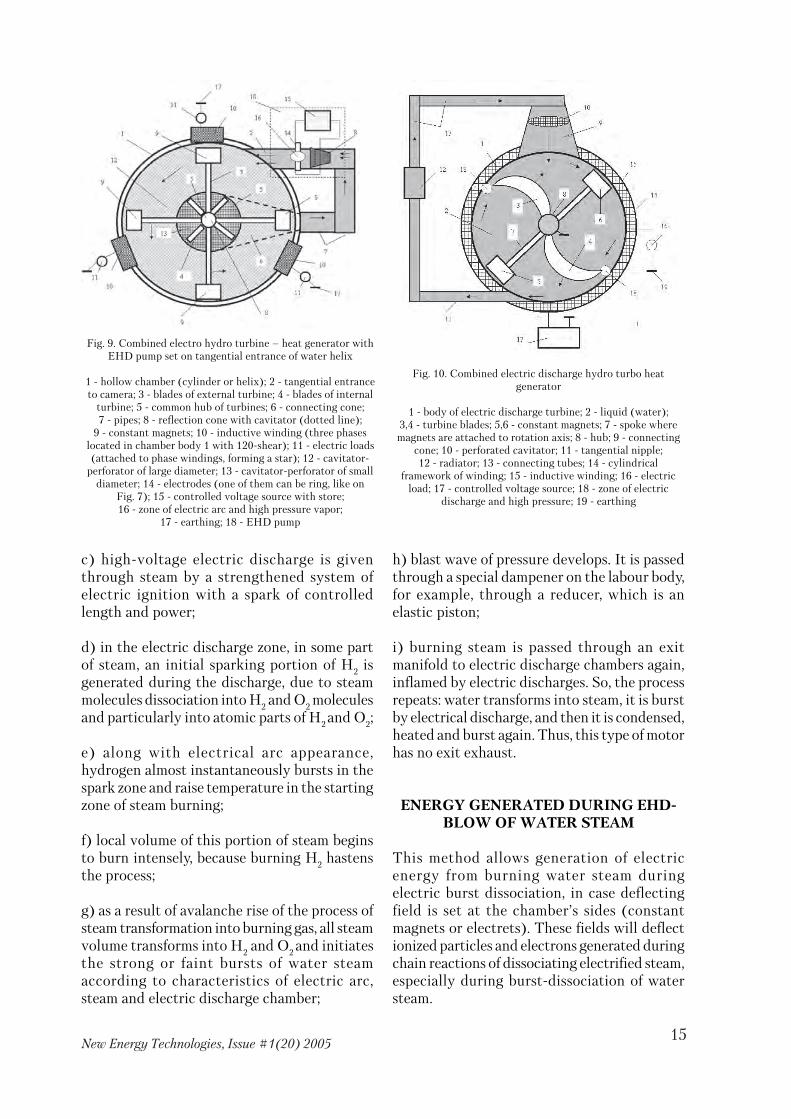
c) high�voltage electric discharge is giventhrough steam by a strengthened system ofelectric ignition with a spark of controlledlength and power;
d) in the electric discharge zone, in some partof steam, an initial sparking portion of Н2 isgenerated during the discharge, due to steammolecules dissociation into Н2 and О2 moleculesand particularly into atomic parts of Н2 and О2;
e) along with electrical arc appearance,hydrogen almost instantaneously bursts in thespark zone and raise temperature in the startingzone of steam burning;
f) local volume of this portion of steam beginsto burn intensely, because burning Н2 hastensthe process;
g) as a result of avalanche rise of the process ofsteam transformation into burning gas, all steamvolume transforms into Н2 and О2 and initiatesthe strong or faint bursts of water steamaccording to characteristics of electric arc,steam and electric discharge chamber;
h) blast wave of pressure develops. It is passedthrough a special dampener on the labour body,for example, through a reducer, which is anelastic piston;
i) burning steam is passed through an exitmanifold to electric discharge chambers again,inflamed by electric discharges. So, the processrepeats: water transforms into steam, it is burstby electrical discharge, and then it is condensed,heated and burst again. Thus, this type of motorhas no exit exhaust.
ENERGY GENERATED DURING EHD�BLOW OF WATER STEAM
This method allows generation of electricenergy from burning water steam duringelectric burst dissociation, in case deflectingfield is set at the chamber’s sides (constantmagnets or electrets). These fields will deflectionized particles and electrons generated duringchain reactions of dissociating electrified steam,especially during burst�dissociation of watersteam.
Fig. 9. Combined electro hydro turbine – heat generator withEHD pump set on tangential entrance of water helix
1 � hollow chamber (cylinder or helix); 2 � tangential entranceto camera; 3 � blades of external turbine; 4 � blades of internal
turbine; 5 � common hub of turbines; 6 � connecting cone;7 � pipes; 8 � reflection cone with cavitator (dotted line);
9 � constant magnets; 10 � inductive winding (three phaseslocated in chamber body 1 with 120�shear); 11 � electric loads(attached to phase windings, forming a star); 12 � cavitator�
perforator of large diameter; 13 � cavitator�perforator of smalldiameter; 14 � electrodes (one of them can be ring, like on
Fig. 7); 15 � controlled voltage source with store;16 � zone of electric arc and high pressure vapor;
17 � earthing; 18 � EHD pump
Fig. 10. Combined electric discharge hydro turbo heatgenerator
1 � body of electric discharge turbine; 2 � liquid (water);3,4 � turbine blades; 5,6 � constant magnets; 7 � spoke where
magnets are attached to rotation axis; 8 � hub; 9 � connectingcone; 10 � perforated cavitator; 11 � tangential nipple;12 � radiator; 13 � connecting tubes; 14 � cylindrical
framework of winding; 15 � inductive winding; 16 � electricload; 17 � controlled voltage source; 18 � zone of electric
discharge and high pressure; 19 � earthing

16New Energy Technologies, Issue #1(20) 2005
It is necessary to deflect particles by electric and(or) magnetic fields during water steam burningand then precipitate, collect them onelectrically insulated electrodes from theelectric discharge chamber. After that, theseions�electrons, electric energy carriers, shouldbe recombined by paying electric load locatedoutside the processing chamber. Hence, ions andelectrons are transformed into electric energy,like in a standard electric chemical energysource. Steam dissociation process can beconsiderably intensified due to influence ofsource of ionizing ultra�shortwaveelectromagnetic radiation, for instance,ultraviolet light from minimal quantity ofradioactive elements located in the chamber.
WHERE IS EXCESS ENERGY,GENERATED DURIN ELECTRIC BURST
OF STEAM, FROM?
To sum up the idea of transforming steam intofuel, let’s ask a simple question: where excessenergy comes from and why this process can berepeated?
Apparently, the unusual electro steam device isan open energy system, i.e. a heat pump usingenergy of environment and self�energy. Watersteam’s structure contains self�energy in itscohesion and atoms. This self�energy of steamas a nonlinear system is released cyclically byEHD�discharge and the following burst. Dueto EHD�burst of steam and steamtransformation into hydrogen gas burned by theelectric spark, the self�energy of steam isreleased gradually. This process of gastransformation into fuel can be used in heatenergy systems. Of course, water solutions ofworthless carbohydrates, for example, intestinaldischarge, can be efficiently used fortransformation into energy by this method dueto methane gases released in the electricdischarge zone. These gases will help to carryout thermo ionization of the steam burningprocess.
Conclusion for the chapter: A technicalpossibility to use EHD�effect exists. Themethod suggests transforming steam into newcheap fuel burned. Its self�energy and heatenergy are transformed then into other types
of energy, which is used in energy systems and transport.
The innovation was experimentally tested on amodel from 1986 till 1989.
CONCLUSIONS
1. It is shown that electrohydraulic Yutkineffect is available for constructing effective heatgenerators of new generation.2. New straight flow and turboprop electrohydro (aero) reactive turbines, engines, pumpswith minimal consumption of electric energyare suggested.3. EHD�method for generating of cheap heat,kinetic and electric energy and combineddevices for its implementing are suggested.4. EHD�method of water steam transformationinto cheap gas fuel and devices are suggestedincluding a standard internal�combustionengine.
SUMMARY
EHD�effect opens new horizons and outlooksfor radical improvement of energy engineeringand transport. New effective methods of cheapheat, kinetic and electric energy generationsuggested. They are based on combined use ofabnormal energy of cavitation and EHD�effectsand their transformation into other types ofenergy. In case these inventions will be realizedas production prototypes and then produced,the suggested devices can be used soon invarious spheres of energy engineering to doworld community and Nature good.
LIST OF REFERENCES
1. L.A. Yutkin. Electrohydraulic effect and its industrial use –L., 1986.2. V.D. Dudyshev. Method of transformation of electrohydraulicblow energy. Patent of the Russian Federation №2157893, 1997.3. Yu.S. Potapov, L.P. Fominskij. Vortex energy systems.Kishinev�Cherkassy, 2000, 387 p.4. Yu.S. Potapov. Heat generator and its design. Patent of theRussian Federation №2045715.5. L.P. Fominskij. Super�unit heat generators against Roman club– Cherkassy, 2003, 432 p.6. I.M. Fedotkin, I.S. Gulyj. Cavitation and cavitation devices –Kiev, 1987, 840 p.7. V.D. Dudyshev. Effect of unipolar charge�liquid mass transferin impulse electric field and its use. – New Energy, 2/2004.8. V.D. Dudyshev. Direct transformation of magnetic fields’energy generated by constant magnets into other types of energy� New Energy, 3/2004.
17New Energy Technologies, Issue #1(20) 2005
ENERGY SAVINGENERGY SAVINGENERGY SAVINGENERGY SAVINGENERGY SAVING(current cycling over loading phases by means(current cycling over loading phases by means(current cycling over loading phases by means(current cycling over loading phases by means(current cycling over loading phases by means
of the operated gates)of the operated gates)of the operated gates)of the operated gates)of the operated gates)
V. D. Dudyshev, Samara, RussiaV. D. Dudyshev, Samara, RussiaV. D. Dudyshev, Samara, RussiaV. D. Dudyshev, Samara, RussiaV. D. Dudyshev, Samara, [email protected]@[email protected]@[email protected]
http://www.ntpo.com/invention/invention2/13.shtmlhttp://www.ntpo.com/invention/invention2/13.shtmlhttp://www.ntpo.com/invention/invention2/13.shtmlhttp://www.ntpo.com/invention/invention2/13.shtmlhttp://www.ntpo.com/invention/invention2/13.shtml
The cost of electric power is constantly growing,and the problem of energy saving is becomingurgent.
Do we know how to use it rationally? I havecertified and patented solutions which allowsaving up to 25 – 30% energy. They are basedon the concept of two types of electric power:active power, which works directly, and reactivepower, which forms magnetic field in variousinductive electrical devices (from solenoidstarters to transformers and inductive motors).Having phase lag, this reactive current justloads a current line according to paying load.
The current makes up from 10 to 50%, which isthe energy saving reserve.
There is a paradoxical and very importantcircumstance: the reactive currents’ sum perperiod amounts to zero in three�phase circuits.
As a result, we can make a circuit for the reactivecurrent flow (reactive electric power flow) fromone loading phase to another according to aworking cycle of the inductive loading and,therefore, all reactive power will be get caughtin cycle.
It won’t load uselessly the electric circuit: andconsiderable energy saving will be obtained dueto reduction of ohmic losses between an energysource and its customers caused by reactivecurrents flow.
I named this concept of energy saving “artificialcirculation” of reactive power over inductiveloading phases.
This method is technically carried out usingsemiconductor no contact high�speed circuitbreakers (thyristors or transistors), which areoperated at the command of the elementssensing angle of shear between current andvoltage in each phase of electric loading. Thisno contact, obedient “controller” of electricpower flow’s direction has rather simple logic.
In case signs of voltage phase and current phaseare the same, a circuit passes through activeelectric power from power grid. In case the signsare different, the electric circuit “catches”reactive current in the required loading phase.
At the same time, the no contact “controller”allows accomplishing reduced�current start ofelectric loading, reducing start currents’ rush,providing thermal protection and maximalcurrent protection of expensive electricequipment.
This simple commutator can also control eitheractive and reactive powers or one of themdepending on a working regime, for instance,depending on degree of motor axis’ loading. Thisinnovation will allow improving energy savingand reliability of electric equipment.
This method of energy saving is the mosteffective in case of inductive loadings with lowpower coefficient, for example, in powerfulinductive heating furnaces.
I am looking forward to find partnersand investors for application of my
innovations to production.

18New Energy Technologies, Issue #1(20) 2005
METHOD OF ELECTRIC ENERGYMETHOD OF ELECTRIC ENERGYMETHOD OF ELECTRIC ENERGYMETHOD OF ELECTRIC ENERGYMETHOD OF ELECTRIC ENERGYGETTING FROM NATURALGETTING FROM NATURALGETTING FROM NATURALGETTING FROM NATURALGETTING FROM NATURAL
ATMOSPHERIC ELECTRICITYATMOSPHERIC ELECTRICITYATMOSPHERIC ELECTRICITYATMOSPHERIC ELECTRICITYATMOSPHERIC ELECTRICITY
V. D. Dudyshev, Samara, RussiaV. D. Dudyshev, Samara, RussiaV. D. Dudyshev, Samara, RussiaV. D. Dudyshev, Samara, RussiaV. D. Dudyshev, Samara, [email protected]@[email protected]@[email protected]
http://www.ntpo.com/invention/invention2/13.shtmlhttp://www.ntpo.com/invention/invention2/13.shtmlhttp://www.ntpo.com/invention/invention2/13.shtmlhttp://www.ntpo.com/invention/invention2/13.shtmlhttp://www.ntpo.com/invention/invention2/13.shtml
Our civilization is seriously concerned by theimminent global energy and ecological crisis. Inthese circumstances, the fact that Naturegenerates abundant quantity of electricitysounds paradoxical. This electricity hangsabove us, in a literal sense. We only have to makethe simplest rope devices and get the requiredquantity of electricity. You don’t believe me, doyou? Then I will describe a new no fuel electricenergy source in details.
It is known that our planet has both electriccharge and electric field. Its intensity is about130 V/m at the surface. Electrical conductionof surface air is very small but it considerablyincreases along the height. There are powerfulflows of Earth atmosphere’s global circulationat 10 km height. These flows can hold analtitude sail or an airship joint with a surfacemast by a strong electric rope. I suggest usingthe electric field of the planet and its renewablenatural electricity (electrically chargedparticles of near�Earth plasma) for energygetting. An electric circuit joint to an electricloading can be easily made using a thin metalrope lifted by an airship at 10�15 km height. Apower of such non�traditional no fuel energysource measured in the surface electrical loadingcan be up to thousands megawatt.
Nature itself creates optimal conditions forusage of the natural electricity at such heights.The atmosphere electrical conduction is highthere, so potential of a natural electric magneticgasdynamic generator reaches hundredskilovolt.
Natural electricity is actually used by Natureand renewed by the natural electric generator.
The electric field and electric charge of theplanet is created by the natural ionosphericmagnetic gasdynamic generator, which worksusing kinetic energy of moving solar plasmawithin Earth’s magnetosphere. Its enormouspower exceeds power of all world electricstations many times. That’s why it is technicallypossible, ecologically safe (in comparison withharm done by the traditional fuel powersystems) and extremely useful to use a smallpart of electric power of the natural ionosphericgenerator with the help of the rope energydevice.
It consists of a thin cable�rope, a holding devicefor the cable (an airship), two plates at the endsof the cable, a device for safe earthing of thelower end of the cable into electroconductiveearth stratum, a device for bonding andcontrolling of rope’s height above Earth.
Such simple no fuel electric station canpermanently give electric power up to a numberof megawatt depending on rope’s length, rope’sheight above Earth, and square of plates. Ingeneral, this cable�rope is located in twoelectroconductive Earth spheres within theenormous electric potential of the naturalionospheric generator. Understandably, it isnecessary to attach the low end of the rope tothe surface electric loading while the loadingshould be safely earthed into electroconductiveearth sphere (which can be moist soil or anatural electrolyte, salt sea water) in order tomake electric current run through the rope. Ithink it would be the simplest way to earthnaturally the rope energy system in ocean or seabecause sea water is rather electroconductive.In order to improve power of the no fuel rope

19New Energy Technologies, Issue #1(20) 2005
electric station, charge plates, havingelectroconductive square as big as possible,should be placed at the ends of the rope. Theupper plate should be attached to theelectroconductive (metal) surface of the airshipwhile the lower plate should be earthed byspecial masts dug deeply in the ground.
Actually, calculations show that the rope“flying” electric station can generateconsiderable electric power (up to 500�600megawatt) without any fuel, in any place onEarth. Due to natural electric potential (up tohundreds of kilovolt) extracted at the ends ofthe rope and due to tapping of some part ofenergy, electric current will run through thethin metal rope, which is electrically contactedwith loading. The current is a result of naturalionospheric condenser discharging from
electroconductive ozone sonde toelectroconductive earth sphere.
Quantity of electric current and loading powerdepends on characteristics of the rope energysystem and loading characteristics. The powercan be controlled by both loadingcharacteristics and characteristics of the ropeenergy system, for example, by the rope’s height.We should mention that, due to strongatmosphere circulation at this height, the ropeenergy system can be used both as a wind�electric set and as a source of mechanicalmovement at seas. In this case, the lower end ofthe rope is attached to a rostrum. Pulled by thestrong wind circulation, the airship will moveships and give free energy from the upperatmosphere. All basic calculations and draft isalready done.
NEW METHODS OF EXTRACTION ANDUSE OF SELF�ENERGY OF MATTER
V.D. [email protected]
In order to learn how to effectively extractself�energy from matter, first we have to knowits meaning and extraction methods. Thisarticle is dedicated to these questions. Anumber of experimental discoveries andauthor’s inventions in the field ofelectrophysics are described.
Energy
Today, according to explanatory dictionariesand encyclopedias energy is determined asability of matter forms to perform work andcommon measure of matter motion [15].However, these definitions are not concreteenough. They clear neither the essence ofenergy nor reasons of motion of all body parts.It is known by intuition that energy is a mainuniversal quality of motion of everything. Butwhat forces move all bodies and the world: frommatter particles to galaxies? Science does not
know this yet. Meaning of the most importantidea of “energy” is vague and its differentinterpretations are rather contradictory. Theterm “energy” appeared in the beginning of XIXcentury and was introduced in mechanics byJung. Joule identified ideas of energy as type ofwork and heat in his experiments. Then,deformations and vagueness of this concept’sinterpretation were increasing, especially sincequantum mechanics formation and discovery ofX�radiation and other types of radiation.Scientists still have no common opinionconcerning the meaning of energy: whether itshould be a property of mater to work or thework, or motion and force characteristics offields, or various types of emissions etc. Crisisof the modern science and the civilization ismainly caused by domination of scientificparadigm about power of law of conservationof energy (LCE) and unproved postulates ofthermodynamics.

20New Energy Technologies, Issue #1(20) 2005
Meaning and application of law ofconservation of energy
As everybody knows, the fundamental LCE isright only for a closed energy system [16]though there are no such ideal systems inNature. The reason of paradox connected withunderstanding of these interrelated ideas(Energy and LCE) is that it is impossible tounderstand the meaning of LCE while truemeaning of energy is vague. Contradictions ininterpretation of the idea of energy were statedabove. The analogous contradictions are ininterpretation of the meaning of LCEconcerning some nonconventional powerdevices using abnormal energy resources. Onthe one hand, science based on the existing awryand imperfect understanding of LCE denies theopportunity to create a device with efficiencymore than 1 and any perpetual motionmachines. On the other hand, science standstheories and practice of different heat pumps(HP), which obtain more energy fromenvironment than consume.
Since HPs are real, in order to adjust thiscontradiction with law of conservation ofenergy, a concept of exergy was introduced inscience as a coefficient of use of environmentenergy. Hence, exergy ratio of the real HP ismuch more than 1 while its efficiency is lessthan 1. However, as science develops, numberof amazing scientific experiments proving thefact of violation of the classical law of energyconservation in open energy systems increases[1,3].
Energy exchange between matters andenvironment
New experimental data on generation of extra�unit energy in comparison with supplied energymake us think that there is an unknown type ofenergy running through environment andfilling the other energy and matter types. Let’scall it energy X or ether energy. To put itdifferently, any matter is an open energy system,an energy pump feeding the matter by thisunknown energy. A method of this energyinterconnection between energy X and matterand known fields is not clear yet. Nevertheless,the constant energy exchange of all bodies andmatters and environment undoubtedly exists
because even the simplest matter particles(electron and proton) are open energy systems.In case we deny the mechanism of their energyfilling by this undiscovered energy ofenvironment, these matter particles violate theknown law of conservation of energy and,therefore, turn into continuously operatingmachines of the first type. The simplest matter“bricks” are open energy systems and actuallyuse environment energy.
Perhaps the energy of physical vacuum supplyelectrons and protons with energy needed fortheir continuous motion. As a result, conditionsare maintained for existence and transformationof matters. In other words, a rightful hypothesisappears that it is vacuum energy that providesfor existence of other energy types and thecontinuous round of matter in nature. Matteritself (field, matter) is an effective energytransformer and accumulator of different typesof energy including energy of physical vacuum.Under certain conditions, this latent self�energyof matters can be discovered, extracted andused.
Numerous scientific experiments prove that itis possible to generate excess energy from self�energy of matters and fields, for example,experiments of Tesla, Avramenko, Serla,Kosinov, Floyd, Kanarev, Kushelev, Potapovand many other experimentalists. Due to thefact of energy exchange between matters andfields as energy concentrators and environment,a fundamental opportunity to use and transformtheir latent self�energy in real energy used inour real engineering exists. These ideasconstitute a physical basis of the new energy ofmatters’ self�energy extraction.
CONCEPT OF LATENT SELF�ENERGYOF MATTERS
The author has analyzed and eliminateddisadvantages of previous definitions of energyand law of conservation of energy and also giventheir new specified definitions [1]. Ways ofelectric field’s self�energy use for yield areshown below. It is known that there is self�energy in any matter type. The problem of itsextraction is that enormous self�energy isadroitly hidden in matter and appears only

21New Energy Technologies, Issue #1(20) 2005
under certain conditions. Sometimes, duringcombustion or autodecomposition of activematerial, self�energy comes off openly and canbe measured and used. But how can we extracteven a minimal part of this enormous self�energy by other ways?
It is difficult to realize methods of effective useof matters’ self�energy in energy engineeringdue to ontological unsolved scientific problemsof energy exchange between matter andenvironment. Hence, the experimental methodwas chosen as the basis for research of effectsand ways of extraction of matter’s self�energy.
Latent self�energy of matter
Latent self�energy of matter is full kineticenergy of motion of all its elements andpotential energy of its structure, i.e. energy ofall intermolecular and intramolecularphysicochemical interactions of matter. In otherwords, this is entire potential and kinetic energyof all matter’s elements (electrons, photons,atoms, molecules etc.). Quantity of self�energyof any matter including liquid is characterizedby its mass. Latent self�energy of any matter canbe determined by the famous Einstein formulaW=m c2 (1), where m is mass of matter and C isspeed of light. For example, a bank of self�energyin 1 kg of water calculated according to theformula (1) is approximately 9 х 1016 joule. It isobvious that using even a small part of latentself�energy of matters is an enormous energyreserve and the mainstream of development ofalternative energy engineering.
MAIN PRINCIPLE OF EXTRACTION OFMATTER’S LATENT SELF�ENERGY BY
EXTERNAL FORCE FIELD. IDEA OFENERGY PUMPS
In order to extract latent self�energy of matter,it is necessary to force it by external force fieldoperating as an energy pump. The pump workslike, for example, a mechanical pump orextraction of toothpaste from a tube by forceand external pressure. Heat pumps are aparticular case of energy pumps, which aredevices transforming self�energy of matters intouseful external energy. During this, matter massand potential energy of external field must
diminish. In order to force self�energy of matter,certain conditions must be created: phasechanges and other energy nonlinearities ofmatter and gradient of external field in mattermust be used. Then, the external field willproduce pressure on all elements of matter.
It is known that pressure is created by force,which is generated by physical field. Hence,internal pressure of matter, for example, liquid,can be produced by external potential electricalfield. Heat, gravitation, mechanical, acoustic,electric, electromagnetic fields etc. are known.Basically, any force field of certain parametersallows extraction of self�energy from matter.
Thus, energy pumps (EP) are field�devices,“extractors” and transformers of latent self�energy of matters. EPs can be classified asnatural and artificial. It is the natural EPs whichprovide for energy and matter circulation innature [4].
We will give some examples of natural EPs.Such energy pumps are created and used inliving Nature for a long time. Earth is not onlya space figure of revolution but also a naturalheat and energy device possessing its owngeomagnetical and geoelectric fields. Theircombination provides for evaporation andcirculation of planet water and also globalcirculation of ocean currents and atmosphere.We will try to use inventions of Nature forcreation of the same energy pumps.
Method of extraction of self�energy ofmatters by external potential field
A new method of extraction of matter’s latentself�energy (MLSE) of differentphysicochemical origin by external potentialfield is suggested. It is simply and effectivelyrealized by, for example, a strong electrical fieldand coulomb repulsive forces of injected sameelectrical charges. Technological basis of themethod consists in primary injection of aunipolar bulk electrical charge in matter (forinstance, in flame, non�polar liquid etc.) andsimultaneous influence on the charge byexternal force field. Method’s developmentmoves towards control of process of extractionand transformation of self�energy by changingof parameters of external vector electric field.

22New Energy Technologies, Issue #1(20) 2005
The suggested method was tested by the authorexperimentally. Some experimental data ofnumerous experiments carried out by theauthor is described below in order to provemarketability and efficiency of this method ofextraction and transformation of MLSE.Concrete examples of experiments conductedby the author and their results are used. Peculiarqualities of use and results of realization of thismethod in processes of new electric�fire matterconsumption and also in someelectrohydrodynamic and electrodynamiceffects and processes are considered as examples.
METHOD OF EXTRACTION OF LATENTSELF�ENERGY OF IMFLAMMABLES
DURING PROCESS OF ELECTRICFIELD’S INFLUENCE ON FLAME [2�4]
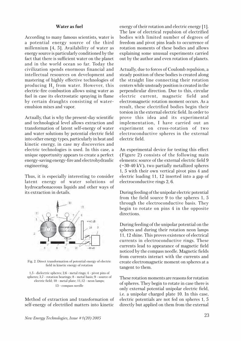
Effect of release of many matters’ latent self�energy is mostly pronounced in the discoveredeffect of flame combustion in strong electricfield (Figure 1). A prototype consists of thefollowing basic elements: a source of strongelectric field 7; two electrodes 5 and 6 set inquadrature and attached to the filed source 7by a switch; capacities 1 with fuel, for instance,aqueous emulsion of straw, and a fir�treeelectrode 2. During feed of electric field on flame4 abrupt increase of flame brightness occurs. Itbecomes flat in vertical plane above electrode 5and directed E�field radiation occurs fixed by asensor 8.
Fig. 1. Control device for matters consumption in electric field
1 � Capacity with fuel; 2 � Electrode; 3 � Candle (fuse);4 � Flame; 5 � Ring level electrode; 6 � Vertical electrode;7 � Source of electric field; 8 � Sensor of E�field radiation
Measurements show that, under conditions offlame combustion in electrical field, total heatand radiant energy of flame increases by 15�20%using the same quantity of fuel, i.e. not onlycombustion intensity but also heat capacityincreases. This effect of specific heat increaseby 15�20% during combustion of these mattersin a flow of emission and in strong electric field[2�4] is connected with presence of fuel and Н
2
evaporated by electroosmosis, which providesfor increase of heat and radiant energy of flame.Effect of combustion intensification in strongelectric fields was discovered by the authorearlier [2�4]. Physics of such combustion dueto combined catalytic influence on flame by thebulk electric charge and strong external field israther complicated.
During these experiments, the author oftenobserved effects of specific heat increase ofinflammables, deep electric�fire andelectrochemical decomposition of combustionproducts and parent substances in theelectrified flame and, as a result, abrupt (by tenhundred times) diminishing of toxicity ofeffluent gases. Energy physics of the abnormalconsumption is not sufficiently investigated yet.It is known that combustion is a complicatedchain reaction of division (fragmentation) ofinternal structure of matter and release.
As a matter of fact, any matters can combustdue to energy of intermolecular and molecularconnections of hydrocarbon fuel. The electric�fire method allows burning in flame almost allmatters including water due to the fact thatelectric field and the injected bulk electriccharge cause other chain reactions in this flame,up to transmutation of some elements: airnitrogen and even water burns because the fielddissociates its molecules on Н
2 and О
2 [7].
Existence of this complicated electrophysics ofcombustion can be proved by increased directedE�field radiation of the electrified flame alongthe axis of the field vector. On the basis oflong�time research of influence of strongexternal electric field on combustion processes,we come to a conclusion that it allowscontrolling the chain reaction of flamecombustion by not only intensificationcombustion but also, in some critical cases,suppressing chain reactions of combustion up toinstant extinguishing of flame [5].
23New Energy Technologies, Issue #1(20) 2005
Water as fuel
According to many famous scientists, water isa potential energy source of the thirdmillennium [4, 5]. Availability of water asenergy source is particularly conditioned by thefact that there is sufficient water on the planetand in the world ocean so far. Today thecivilization spends enormous financial andintellectual resources on development andmastering of highly effective technologies ofproducing Н
2 from water. However, this
electric�fire combustion allows using water asfuel in case its electrostatic spraying in flameby certain draughts consisting of water�emulsion mixes and vapor.
Actually, that is why the present�day scientificand technological level allows extraction andtransformation of latent self�energy of waterand water solutions by potential electric fieldinto other energy types, particularly in heat andkinetic energy, in case my discoveries andelectric technologies is used. In this case, aunique opportunity appears to create a perfectenergy�saving energy�fire and electrohydraulicengineering.
Thus, it is especially interesting to considerlatent energy of water solutions ofhydrocarbonaceous liquids and other ways ofits extraction in details.
Fig. 2. Direct transformation of potential energy of electricfield in kinetic energy of rotation
1,5 � dielectric spheres; 2,6 � metal rings; 4 � pivot pins ofspheres; 3,7 � rotation bearings; 8 � metal basis; 9 � source of
electric field; 10 � metal plate; 11,12 � neon lamps;
13 � compass needle
Method of extraction and transformation ofself�energy of electrified matters into kinetic
energy of their rotation and electric energy [1].The law of electrical repulsion of electrifiedbodies with limited number of degrees offreedom and pivot pins leads to occurrence ofrotation moments of these bodies and allowsexplaining some unusual experiments carriedout by the author and even rotation of planets.
Actually, due to forces of Coulomb repulsion, asteady position of these bodies is created alongthe straight line connecting their rotationcenters while unsteady position is created in theperpendicular direction. Due to this, circularelectric current, magnetic field andelectromagnetic rotation moment occurs. As aresult, these electrified bodies begin theirtorsion in the external electric field. In order toprove this idea and its experimentalimplementation, I have carried out anexperiment on cross�rotation of twoelectroconductive spheres in the externalelectric field.
An experimental device for testing this effect(Figure 2) consists of the following mainelements: source of the external electric field 9(=30�40 kV), two partially metallized spheres1, 5 with their own vertical pivot pins 4 andelectric loading 11, 12 inserted into a gap ofelectroconductive rings 2, 6.
During feeding of the unipolar electric potentialfrom the field source 9 to the spheres 1, 5through the electroconductive basis. Theybegin to rotate on pins 4 in the oppositedirections.
During feeding of the unipolar potential on thespheres and during their rotation neon lamps11, 12 shine. This proves existence of electricalcurrents in electroconductive rings. Thesecurrents lead to appearance of magnetic fieldnoticed by the compass needle. Magnetic fieldsfrom currents interact with the currents andcreate electromagnetic moment on spheres at atangent to them.
These rotation moments are reasons for rotationof spheres. They begin to rotate in case there isonly external potential unipolar electric field,i.e. a unipolar charged plate 10. In this case,electric potentials are not fed on spheres 1, 5directly but applied on them from the external

24New Energy Technologies, Issue #1(20) 2005
field of the plate 10 attached to the source 9 byelectrostatic and electrodynamic induction.This physical effect of rotation of bodies inelectrical field is an example of directtransformation of potential energy of electricfield in kinetic energy. New types of effectiveelectrostatic motor�generators can be createdon the basis of this electrophysical discovery.
Method of heat energy extraction frommatter (liquid) using electric field and
simultaneous cooling of the matter [11]
Such extraction of heat energy of bodies’molecules and atoms can be most effectively andnon�contact implemented by a strong vectorelectric field (with tension higher than 1 – 5kV/cm) and used, for example, for cooling ofliquids in electrical field (Figure 3). One high�voltage electric potential is fed directly on theheated body, for instance, 30 – 40 kV throughthe electrode 2 placed in the liquid 1, from thelow�power high�voltage source 4 – electric fieldsource. The second electric potential is fedthrough the pointed electrode 3 placed abovethe liquid. It is isolated from the tested body byan air�gap.
Earlier the author experimentally discoveredand repeatedly observed the effect of intensecold vaporization and cooling of liquids in thestrong direct�stress electric field along withrotation of the liquid above the remote
electrode and appearance of intensive, directedE�field radiation along the vector (flux) of thisfield. Physical meaning of this effect consists inthe fact that flux of the field and coulomb forcesinhibit heat motion of molecules and atomspolarized in the field, directed at an anglediffered from zero to them.
Due to this, re�orientation of molecules’doublets and the heat motion of the particlesaccording to the field vector as the less power�consuming type of motion in the filed due toincrease of heat energy density along the axisof the filed vector.
During this process, latent self�energy of theheated matters discharges: excess heat energyis removed by photons of atoms and moleculesin the form of directed E�filed radiation (mainlyin infrared spectrum) occurring along the fieldvector. Electric field is the energy pump anddirect transformer of heat energy of the body.
Due to this forced radiation, the electrified bodytakes away excesses of heat motion of moleculesand atoms providing for its effective cooling.This effect of intensive cooling of bodies instrong electric field was observed by us in manyexperiments, when different matters were used:from metals to dielectric liquids. The effect ofbodies’ cooling by electric field, discovered byme, occurs due to regulated motion of moleculesand atoms in these bodies along the electric fieldvector. Effect of intensive heat energy emittingfrom bodies of different physical nature in theform of directed E�field radiation is, most likely,is a reciprocal reaction of the cooling body toexternal disturbance – impact of electric field.It is entirely natural in full accordance withphysical laws.
Experiments have proved that bodies cool inelectrical field much faster than under naturalconditions. Speed of the unusual electriccooling is proportional to the value of electricfield strength and is much higher than speed ofnatural cooling.
This electro�heat effect can be used in differentways: both for cold and heat energy generation.For example, it is possible to design a highlyeffective closed heat pump extracting heatenergy of the environment by the strong field.
Fig. 3. Device for cooling liquids by electrical field andextraction heat energy from liquid
1 � capacity with water; 2 � pointed internal electrode;3 � pointed external electrode; 4 � high�voltage source;
5 � bushing; 6,7 � induction and outlet pipes; 8 � receiver ofE�field radiation; 9 � transformer of E�field radiation;
10 � directed E�field radiation; 11 � zone of intense watervaporization
25New Energy Technologies, Issue #1(20) 2005
The pump pumps an environment, for instance,air or liquid, across the electric filed cooler andtransforms it into heat energy and then in otherenergy types: electric energy or kinetic energyof motion. The process of cooling bytransformation of directed E�filed radiationextracted from heat energy into electric energycan be of low power inputs, in case we obtain asource of electric field from the extracted andtransformed electric energy and, therefore, coolbodies more actively. A particular case of thiseffect occurrence is an instant fire extinguishingdue to its cooling by strong cross electric vectorfield (Figure 1 – through electrode 6). Thisphysical effect can be used for designingefficient noiseless compressorless refrigeratorsand air�conditioners of new generation.
CONCLUSIONS
1. The general method of release of matters’latent self�energy is the following: external forcepotential field is applied on matter creatinginternal voltage inside it using nonlinearities ofthe matter.
2. Device for extraction of self�energy ofmatters operates as an energy pump. The pumpsare divided into natural and artificial ones.
3. The value of extracted energy depends oncombination of parameters of the energy pumpand matter. Energy balance is filled up byenvironment matter.
4. Under certain conditions, latent self�energy of matter can be extracted under theinfluence of electric filed energy pump in theform of directed E�field radiation, kinetic orelectric energy of this matter’s motion. As aresult, properties of matter and its sefl�energychanges.
5. Value and type of extracted energy dependson parameters of energy pump and parametersof external electric field.
6. Electric field and the unipolar electriccharge injected by it, for example, as explosiveemission, are two main force influences for self�energy extraction according to the Dudyshevmethod.
7. Methods of extraction of matters’ latentself�energy by electric fields can provide thecivilization for cheap pure kinetic and electricenergy in future.
REFERENCIES
1. Dudyshev V.D. Method of extraction of latentpotential energy of electric field and itstransformation into other energy types // NewEnergy Technologies, #4, 2003.2. Dudyshev V.D. New electro�fire technologyof ecologically clean consumption // NewEnergy Technologies, #1, 2003.3. Dudyshev V.D. “Method of flameconsumption control” // Patent of the Russianfederation # 071219, 19.04.94.4. Dudyshev V.D. “Method of intensificationand control of flame consumption”, Patent ofthe Russian federation #2125682. 5. Dudyshev V.D. New electric technology offire extinguishing and preventing. “Ecology andindustry of Russia”, December 2003.6. V. D. Dudyshev. New Fuelles Spage PoverEngineering –New Energy Technologies –December 2002.7. Dudyshev V.D. Effect of cold vaporization ofliquids// New Energy Technologies, #1, 2003.8. Yutkin L.A. Electrohydraulic effect. M. – L.Mashgiz, 1995. 9. Dudyshev V.D. Method of transformation ofelectrohydraulic blow energy. Patent of theRussian Federation # 2157853.10. Dudyshev V.D. Method of gas pressurecontrol – application for invention #2001132477.11. Dudyshev V.D. Method of thermo�electriccooling of bodies and device for itsimplementation – application for invention#9711011534.12. Kosinov N.V. Energy phenomenon ofvacuum // “Ecology and industry of Russia”,December 2003, p.26.13. Kanarev F.M. Prospects of hydrogen energyengineering // New Energy Technologies, #14�15, 2003.14. Yu.S. Potapov. Energy of rotation. М., 200115. Big Encyclopedia, М.,1991, p. 699.16. Physical Encyclopedia, М., 1984, p. 502.

26New Energy Technologies, Issue #1(20) 2005
Contemporary civilization surely suffers twoglobal problems which hinder its development,and these are energy and ecology. This is provedby UN address to the global community and theworld known Kioto Ecological Treaty whichstates the beginning of global ecological crisis,changes of climate, and endeavors to create aunified strategy of all countries in terms ofconservation, namely restriction of toxicexhaust and carbon oxides into the atmosphere,and which is up till now not ratified by the USA.But the attempts of the world community toresolve these global and interrelated problemsby means of administrative measures show itsinability to find the way out. So far thealternative power engineering is uncapable tocope with this developing global crisis. So, isthere a way out and where is the way to savethe human civilization? In my opinion, this newand radical way of the world community liesthrough the development of the new methodsto utilize and introduce into practice the energyof electrical and magnetic fields to create pureand effective technologies, � which is what Ipropose. This will result in abundant energyresources and simultaneously solve the globalecological problem. My report is dedicated tothe nature and the meaning of the newinventions and new technologies of ProfessorDudyshev.
Overall Methodology and Nature of theProposed New Technologies
If humanity wants to obtain new paradigm andstrategy of stable development, it has to re�
assess the physics and role of electrical andmagnetic fields in natural and technologicalprocesses as well as it has to find the effectivemeans of their utilization. These inventions anddiscoveries will open the humanity a way tocreate new generation of thermocompressors,which will help to solve the global energyproblem by means of development of low�cost,ecologically clear method to produce cheaphydrogen and useful types of energy(mechanical, thermal and electrical)[1,2,21,27,35,50�55].
These inventions and discoveries are brieflyannounced in the articles published in the worldweb at:
http://www.sciteclibrary.ru/rus/catalog/pages/7601.htmlhttp://ntpo.com/invention/invention2/8.shtml
Since I am very much limited by the format ofthis notice I only give a couple of examples ofmy discoveries and the most significantpioneering inventions as well as new electricaltechnologies based on them. Owing to theireffectiveness, they can revolutionize science andtechnology, transport and other fields, all in thenearest future.
Electrical Field and Pure Burning. FireTechnologies by Professor Dudyshev
I have discovered that electrical fields withcertain parameters exert powerful catalytic
Revolutionary discoveries,Revolutionary discoveries,Revolutionary discoveries,Revolutionary discoveries,Revolutionary discoveries,inventions and technologiesinventions and technologiesinventions and technologiesinventions and technologiesinventions and technologies
designed by Professor Dudyshev,designed by Professor Dudyshev,designed by Professor Dudyshev,designed by Professor Dudyshev,designed by Professor Dudyshev,
V. D. DudyshevV. D. DudyshevV. D. DudyshevV. D. DudyshevV. D. [email protected]@[email protected]@[email protected]
Samara Technical UniversitySamara Technical UniversitySamara Technical UniversitySamara Technical UniversitySamara Technical UniversitySamara Department of Russian Ecological AcademySamara Department of Russian Ecological AcademySamara Department of Russian Ecological AcademySamara Department of Russian Ecological AcademySamara Department of Russian Ecological Academy
Russia, city of SamaraRussia, city of SamaraRussia, city of SamaraRussia, city of SamaraRussia, city of Samara
27New Energy Technologies, Issue #1(20) 2005
effect on the process of combustion [1]. Thisphenomenon opens the way to effectivelycontrol the combustion of substances fromintencification to total quenching [1,2]. Basedon this discivery, which was experimentallyproved by many of the world known scientists,I propose a whole range of ecologically pure andintensive electric combustion technologies. Inparticular, to save fuel at heat stations, to createan ecologically clear automobile engine, for pureutilization of waste by means of electricalcombustion and transformation of waste intofirst�class fuel, as well as for momentary non�contact fire extingwishing [1�31]. Following arethe addresses of my articles published in theWWW:
http://ingenrw.narod.ru/Dud/Opi2.htmlhttp://ntpo.com/techno/techno3/11.shtmlhttp://ecip.newmail.ru/iss/2002/0502.htmhttp://www.ntpo.com/invention/invention3/19.shtml
Electrical Field and Cheap Hydrogen. Fuel GasGenerated from Water and Aqueous SolutionsI have discovered the phenomenon of IntensiveCold Capillar Evaporation of fluids inside of thepowerful electric fields along with theirsimultaneous dissociation into H
2 and fuel gas.
Based on this I have proposed andexperimentally proved new effective H
2�fuel
technologies [32�35].
Details see in my articles at:
http://www.sciteclibrary.ru/rus/catalog/pages/7599.htmlhttp://www.efir.com.ua/rus/a.php?r=0&d=1http://ecip.newmail.ru/iss/2004/0804.htmhttp://www.ntpo.com/techno/techno2/6.shtml
Electric Field and New CoulombElectromechanics by Prof. Dudyshev
I have discovered a new phenomenon ofexplosive electron emission and powerful waveof pressure in fluids and gases inside of impulseelectrical and electromagnetic fields andproposed new effective methods of utilizationof the energy of electric field in powerengeneering and technology [36�39]. These
inventions open the way for supereffective andlow�cost methods of transforming energy ofelectric field into kinetic energy. I have alsoproposed new non�contact electric�field motorsand generators. More details see in my articlespublished in WWW at:
http://ntpo.com/physics/studies/23.shtmlhttp://www.faraday.ru/ruscontent17.htmlhttp://www.valery12.narod.ru/index1.htmhttp://www.efir.com.ua/rus/a.php?r=2&d=22http://www.faraday.ru/ruscontent13.html
New Magneto�Mechanical Phenomena.New Magnet�Mechanic�Electrical Power
Engineering by Prof. Dudyshev
I have discovered the phenomenon of directtransformation of magnetic energy ofpermanent magnets into various types of energy,and in particular into kinetic energy andelectrical energy. I have also proposed methodsand various mechanisms to practically utilizethis phenomenon in power engineering andtechnology [39�41].
http://ntpo.com/invention/invention2/25.shtmlhttp://ntpo.com/invention/invention2/27.shtml
New Effective Method of Conversing ofEnergy of ElectroHydroDynamic Impact
into Cheap Heat and Various Types ofEnergy
I have developed, approved and patentedcavity� electrohydraulic method to utilize theYutkin electrohydro impact effect to obtaincheap heat and electrical energy [42].
http://www.ntpo.com/techno/techno2/7.shtml
Inventions based on this phenomenon open theway for new electrohydrodynamic powerengineering and mechanics to producesupereffective and low cost heat generators,electrical charge water turbines, hydro� turbo�thermal� and electric generators, fuel freetransport engines.

28New Energy Technologies, Issue #1(20) 2005
RADICAL ELECTRICAL ENERGYSAVINGS
I have proposed, approved and patented anovel effective method to radically saveelectrical energy (30�40%) by means offorced elimination of reactive currents in“source�alternatig current load” circuits[43�46] . These inventions arerevolutionary for the global powerengineering and are able to help savesubstantial amounts of electrical energy.
More details see at: http://www.ntpo.com/techno/techno2/8.shtml
Renewable Energy of Geoelectricity andGeomagnetism and the Means of their
Utilization for the Global Electrical andHeat Power engineering
I have discovered how electrical charge andelectrical and magnetic field of the Planetand its ionosphere are formed andexplained in the new way, f rom theelectromechanical point of view, and basedon the above mentioned discoveries, thereasons for a l l natural phenomenaincluding the Planet’s rotation and knownnatural anomalies [50�55].
On the basis of these fundamentaldiscoveries, I have proposed methods toobtain cheap electrical energy by means ofutil ization of the renewable energy ofionosphere and magnetosphere of the Earthand novel methods of cutting the result ofglobal warming or its total elimination, aswell as cutting the results of all naturalanomalies [50�55].
1. By means of dosated e lectr icaldischarge of ionosphere by a laser beam[55].2. By means of utilization of Planet’sgeomagnetic field to produce electricalenergy [50].3. Methods of control of Planet ’selectrical charge and magnetic field inorder to to control the natural phenomenaand prevent global warming [50].
More details see at:
h t t p : / / n t p o . c o m / s e c r e t s _ g r o u n d /secrets_ground/14.shtmlhttp://www.sciteclibrary.ru/rus/catalog/pages/7600.htmlhttp://kuasar.narod.ru/library/new�space�energy/http://kuasar.narod.ru/library/new�space�energy/space�capacitors.htm
Conclusions:
1. Above mentioned discoveries ,inventions and methods of utilization ofenergy of electrical and magnetic fields arevery useful to effectively overcome theglobal energy and ecological crises sincethey open the way to ecologically pureproduction of hydrogen, gas synthesis andall useful types of energy in quantitiesabundant for the visible future.2. New Electro�combustion technology ofextingushing of f i re and the newesttechnologies for the prevention of naturalanomalies will help save millions of livesfrom man�caused and natural cataclysms.3. New electrical combustion technologyhelps effectively and purely utilize any typeof waste and converse it into useful fuel aswell as to manufacture ecologically cleartransport engines.4. New electroosmotic technology helpsto effectively obtain cheap hydrogen andfuel gas from any aqueous solution.
References
1. Dudyshev V.D. “Electric Combustion technologies –eefect ive means to so lve the problems of powerengeneering and ecology” //”Ecology and Industry ofRussia” issue 3/1997.2. Dudyshev V.D. “How we can save civilization andnature from global pollution?”// ”Ecology and Industryof Russia” issue 11/1997.3. Dudyshev V.D. “New Electr ic Combust iontechnology for Ecologically Clear Burning” //”The NewEnergy Tchnologies” issue 1/2003, Saint Petersburg.4. Dudyshev V.D. “ New Method of Ecologically PureBurning of Substances as a radical Way to resolve theGlobal Ecological Problems” – Collected Reports of theII International Congress, Russia, Samara, 1997.5. Dudyshev V.D. “Methods of Exhaust Treatment inInternal Combustion engines – Electric CombustionTreatment and Electric Filter at ICE outflow” Patent of

29New Energy Technologies, Issue #1(20) 2005
RF #1404664.6. Dudyshev V.D. “ New Electr ic Combust iontechnology to Intensify the Burning Processes” Report atInternational Scientific and Practical Conference “Ecologyof Big Cities”, Moscow, 1997.7. Dudyshev V.D. “methods to Control the Burning ofFire” – Patent of RF # 22017219, priority of 19.04.94.8. Dudyshev V.D. Methods to Intensify and Control theBurning of Fire” – patent of RF # 2125682 with priorityof 06.06.95.9. Dudyshev V.D. “Methods of Electrical Combustionof Waste” – Patent of RF # 2117870.10. Dudyshev V.D. “Method of Electrical CombustionTreatment of Waste Gas” – Patent of RF #2125168.11. Dudyshev V.D. “Methods to Intensify Combustion inthe Furnace of a Boiler Plant” – Patenet of RF #2079766with priority of 14.06.95 (Electric Combustion Method).12. Dudyshev V.D. “Method to Reduce Toxicity ofAutoTransport Exhaust Gas” – Patent of RF 32117179,priority of 20.02.96 (Electric Combustion Method).13. Dudyshev V.D. “Method of Internal Treatment ofExhaust Gases of ICE” – Patent of RF #2165031.14. Dudyshev V.D. “Method to Intensify the Work ofICE” – Patent of RF #2135814.15. Dudyshev V.D. “Method to Reduce Toxicity ofExhaust Gases of ICE and Apparatus to Implement this”– Patent of RF #2132471.16. Dudyshev V.D. “Methods to Intensify and ControlCombustion” Patent of RF # 215682.17. Dudyshev V.D “Methods o f Control l ing HeatMachine” – Patent of RF # 2134354.18. Dudyshev V.D “Method to Extinguish the Oil WellFire and Apparatus to Implement this” – Patent of RF#2176050.19. Dudyshev V.D “Methods o f Burning Fuel andApparatus to Implement this” pat. Of RF # 2160414.20. Dudyshev V.D. “Method of Burning of Fuel Blend inICE and Apparatus to Implement this” Pat . Of RF#2160380.21. Dudyshev V.D. “Method of Fire Extingwishing’Author’s Certificate Of USSR # 1621234.22. Dudyshev V.D. “Method of Electrical CombustionTreatment of Exhaust Gases of ICE and Apparatus toImplement this”�Patent of RF #2175074.23. Dudyshev V.D. “New Electrical Combustion Methodto Burn Waste” – Collected reports of III InternationalEcological Congress, Russia , Samara, 1998.24. Dudyshev V.D. “Ecological Safety of Auto Transport”// “Ecology and Industry of Russia”, issue 5/1997.25. Dudyshev V.D. “Long�Term Developments andInventions for Ecological Improvement of Auto transport”// “Ecology and Industry of Russia”, issue 12/1998.26. Dudyshev V.D. “Problems and Ways to ImproveDomestic Auto transport” // “Ecology and Industry ofRussia” issue 11/1998.27. Dudyshev V.D. “Ecologically Clear Engine for AutoTransport” // “New Technologies” magazine, issue 2/2001,Samara.28. Dudyshev V.D. “New Electrical Technology of Non�Contact Fire Extinguishing and Fire Prevention” // “NewTechnologies magazine, issue 9/2002, Samara.29. Dudyshev V.D. “New Technology of FireExtinguishing and Prevention” // “Ecology and Industryof Russia”, december, 2003.30. Dudyshev V.D. “Electric Combustion Utilization ofOil�slime” // “ Ecologu and Industry in Russia”, May, 200231. Dudyshev V.D. “Fuel saving and Reduction ofToxicity of Benzine Engines” // “Ecology and Industry inRussia” , May, 2003.32. Dudyshev V.D. “New Effect of Cold Evaporation andDissociat ion of Fluids Based on the Capi l larElectroosmotic Effect” // “new Energy technologies”,issue 1/2003, Saint�Petersburg.
33. Dudyshev V.D. “Method of Electrical Dissociation ofFluids” // application for invention #2000119894.34. Dudyshev V.D., Zavyalov S.Y. (RU) Method forDissociating of a Fluid – Requested patent WO0207874 –Application # WO2001RU00308 20010725.35. Dudyshev V.D. “Cheap Fuel Gas and HydrogenDerived from Aqueous Faeces Solutions”. // “Ecology andIndustry in Russia”, August, 2004.36. Dudyshev V.D. “Method of Electromechanica lEnergy Conversion” – Patent of RF # 2182398.37. Dudyshev V.D. “New methods of Extraction andConversion of Latent Potential Energy of Electrical Fieldinto Kinetic Energy and Electrical Energy” // “Newenergy technologies” issue 4/2003.38. Dudyshev V.D. “Phenomenon of Unipolar Transferof Mass and Charge in the Impulse Electrical Field andIts Practical Implementation in power Engineering andtechnology” // “New Energy technologies”, July, 2004.39. Dudyshev V.D. “Direct transfer of Energy of magneticFields of Permanent Magnets into Various types ofEnergy” // “new Energy technologies”, issue 3/2004.40. Dudyshev V.D. “Methods of Conversion of magneticEnergy of Permanent Magnets and Principles of Work ofMagnetic Field Energy Converters”.// “New EnergyTechnologies”, issue 4/2004.41. Dudyshev V.D. “Magneto�Electrical Field generator”//RF Patent Bureau Resolution for Patenting dated28.10 .2004 , requested patent # 2004129231 dated4.10.2004.42. Dudyshev V.D. “Method of Converting of energy ofElectro�Hydraulic Impact” // patent of RF #2157893.43. Dudyshev V.D. and others. “Voltage Controller”Author’s Crtificate #1372464.44. Dudyshev V.D. “Voltage Control ler” Author ’ scertificate #1389634.45. Dudyshev V.D. and others. “Apparatus for Connectingof User to Alternating current Network” // Author’Certificate # 1537100.46. Dudyshev V.D. and others. “Apparatus rot startingand Protection of Induction Electric Motor”// Autor’sCertificate #1582308.47. Dudyshev V.D and others “Direct�drive Wind powerStation”// Author’s certificate #1263904.48. Dudyshev V.D. and others. “Direct Drive Wind powerstation” // Author’s Certificate #1295025.49. Dudyshev V.D. and others . “Future Trends o futilization of Induction Starter Generators in Auto cars”// “Electrical technologies”, issue 11/1980.50. Dudyshev V.D. “Planet Earth� natural ElectricalMotor generator” // “New Electric technologies” issue 3/2004.51. Dudyshev V.D. “Introduction into Global Ecology orElectromechanics of the Animate Nature” // “Ecology andIndustry in Russia” November. 1999.52. Dudyshev V.D. “Planet earth – Natural ElectricalMachine” // “Technology for Youth” issue 11, 1984.53. Dudyshev V.D. “Method of Eternal Orbita lMovement around the Planet” // Requested Patenet of RF#2002101749�Russin Patent Bureau.54. Dudyshev V.D. “method of Controlling Planet’sClimate by Means of Stabilization of its Magnetic Field”// Requested Patent of RF #2002101750�Russian PatentBureau.55. V.D.Dudyshev New Fuelles Spage Pover Engineering–New Energy Technologies –decemder 200256. V.D.Dudyshev New Electric Fire Technology � NewEnergy Technologies –Januar 2003.57. V.D.Dudyshev New Effekt of gold Evaporation� NewEnergy Technologies –Januar 2003.58. V.D.Dudyshev Latent Potential Energy of ElectricalField � New Energy Technologies –Juli 2003.

30New Energy Technologies, Issue #1(20) 2005
News from Integrity ResearchNews from Integrity ResearchNews from Integrity ResearchNews from Integrity ResearchNews from Integrity ResearchInstituteInstituteInstituteInstituteInstitute
Thomas Valone [email protected] USAThomas Valone [email protected] USAThomas Valone [email protected] USAThomas Valone [email protected] USAThomas Valone [email protected] USA
Canadian ResearcherInvents New Solar Cell
TORONTO (Reuters) � It may only be a matterof time before we will be using our shirts tocharge our cellphones. Researchers at theUniversity of Toronto have invented a flexibleplastic solar cell that is said to be five times moreefficient than current methods in convertingenergy from the sun into electrical energy.
Team leader Ted Sargent, a professor ofelectrical and computer engineering at theuniversity, said the cell harnesses infrared lightfrom the sun and can form a flexible film on thesurface of cloth, paper or other materials. Andthe film can turn 30 percent of the sun's powerinto usable electrical energy � a far betterperformance than the 6 percent gleaned fromthe best plastic solar cells now in use.
"The fact that these materials harness the sun'senergy using flexible materials potentially couldallow you to weave the plastics into fibers, sortof the way we have synthetic fibers already, andto weave those into clothing and makesomething that's a wearable solar cell," Sargentsaid from Boston, where he is working until thesummer.
"That's sort of portable electricity." Sargent saidthe coating could be woven into a shirt orsweater and used to charge an item like acellphone. "We expect that our cellphones orour e�mail can go anywhere with us, but wedon't have that expectation of a continuoussupply of power. The best that we have isbatteries, which run out," he said. "So if wecould have a wireless source of power like howthe sun would provide, this would be prettyexciting."
Research about the new cell was published inthe Sunday online edition of the scientificjournal Nature Materials, and Sargent said hewas now looking for investors who could turnthe invention into a commercially viableproduct.
Terry White, president of the Solar EnergySociety of Canada said solar cells on these linescould transform the industry. "If they make(solar cells) both less expensive and thepotential applications more varied, then it's amajor breakthrough," he said. Sargent said thetechnology could be available to the averageconsumer within five to ten years. But it alreadyhas Wall Street venture capitalists interested.
"The technology really caught my eye both inthe scientific literature and the businessprospects," said Josh Wolfe, managing partnerat Lux Capital in Manhattan, a venture capitalfirm that makes an estimated $1� to $2�millionU.S. investment per project in early stagenanotechnology.
"So the concept of having rollable newspaperdisplays or other things that could power yourlaptop or portable devices or create newproducts that are best left to the creativity ofthe engineers, to me, it represents a pretty sea�change."
So what happens if the sun doesn't shine?"There is obviously no power in the visible(light)," said Sargent. "But in the infrared, it'snot completely zero power. It doesn't have tobe as hot as the sun, but everything that's warm,gives off some heat. Even people and animalsgive off heat.
So there actually is some power remaining inthe infrared even when it appears to us to bedark outside."

31New Energy Technologies, Issue #1(20) 2005
IT was a year that people in the oil markets areunlikely to forget � a year that prices set records,forecasts lost touch with reality, and almosteverything that could go wrong, did. It was alsoa year that politics returned to the oil market.
And the trend is likely to continue this year.While oil prices have declined since October,many of the issues that have vexed the oilindustry in 2004 are expected to recur. Cheapoil increasingly looks like a thing of the past.
Through the 1990's, prices were stable, supplieswere secure and there was plenty of extracapacity to keep energy costs low and worldgrowth buzzing. At an average of $20 a barrel,oil was viewed as just another commodity.
But then came ethnic and labor troubles inNigeria; chaos and protests in Venezuela beforePresident Hugo ChАvez won a referendumallowing him to stay in power; hardball energypolitics in Russia; and the continuinginsurgency in Iraq.
While supplies of oil to the world markets wererarely interrupted, the uncertainties created bythese events raised crude oil prices in New Yorkby two�thirds this year, to a high of more than$55 a barrel in October. And as energy costssurged, many analysts, traders and politicianswoke up to the reality that oil was different fromcocoa or coffee.
"Oil is a political commodity," said RobertMabro, president of the Oxford Institute forEnergy Studies, one of the world's foremostenergy experts. "Geopolitics is the mostfundamental issue if you're looking at oilmarkets. People seem to have forgotten thatsince the 1980's."
Of course, this is not the first time that oil andpolitics have mixed.
Decades ago, militant governments in Iran andLibya, for example, nationalized their oil
sectors, forcing American and Europeancompanies out and taking charge of theirnatural resources. Then came the oil embargoand the price shocks of 1973�74 and 1978�81,with long lines for gasoline and steep rises ininflation.
But for the most part, politics had dropped offthe energy map since then. In the 1980's, energyexperts largely discounted a war between twoof the Persian Gulf's top oil producers, Iran andIraq, because Saudi Arabia and some otherOPEC nations could simply crank up theirproduction to make up for losses.
Even the invasion of Kuwait by Iraq in thesummer of 1990, and the subsequent embargoon their oil exports, roiled energy markets foronly a few weeks.
But in recent years, the oil industry hasundergone a fundamental change. Whiledemand has steadily increased each year, theindustry's exploration efforts have not kept pacein new discoveries.
Now that worldwide production is running atfull speed to meet increased demand, there isno cushion left in the system to weather apotential blow to producers like Iraq, Venezuela,Iran, Russia or Nigeria. So, once again for oilmarkets, politics matters.
For instance, said Amy Myers Jaffe, theassociate director of Rice University's energyprogram, Saudi Arabia's oil industry is no longerseen as being impenetrable to terrorist attacks;tensions in the Persian Gulf could swell overIran's nuclear program; Nigerian factions mayerupt in violence; and the fighting in Iraq goeson.
"All kinds of things can affect this market," Ms.Jaffe said, "especially when you're in a razor�thin situation. The only thing that coulddramatically alter the outlook is a majoreconomic recession."
The heightened geopolitical risk has translatedinto higher prices, something analysts call a"risk premium." Crude oil prices have averaged$30 a barrel since 2000, but last year crude oilin New York climbed to an average of $41 a
With Geopolitics,Cheap Oil Recedes
Into Past

32New Energy Technologies, Issue #1(20) 2005
US Review RekindlesCold Fusion Debate
barrel. While energy prices are high, adjustedfor inflation they are below the level in March1981, when crude oil approached $70 a barrelin today's dollars. Still, analysts do not expectprices to fall anytime soon.
High world prices since mid�2002 have helpedsustain the economic recovery of Russia, whichis raising output, according to the EnergyInformation Agency of the Department ofEnergy.
The former Soviet Union, of which Russia is byfar the biggest country, is the world's largestproducer, the agency says, followed by SaudiArabia and the United States. The biggestconsumers are the United States, which importsover half its needs; China; Japan; and the formerSoviet Union, which uses about a third as muchas it produces. Leo Drollas, chief economist forthe Center for Global Energy Studies inLondon, expects oil prices to be higher in 2005,on average, than they have been this year. Theinstitute was founded in 1990 by Sheik AhmedZaki Yamani, the former Saudi oil minister.
Even oil companies, which are usuallyextremely conservative about their priceoutlook, are coming around to that realization.Lord Browne, the chief executive of BP, nowsees a new bottom of $30 a barrel for the nextfew years.
"There is something fundamental holding pricesup, whether that's at $45, $40 or $35 a barrel,"Mr. Mabro of the Oxford Institute said. "Andpolitics won't improve things. Except if youbelieve a miracle is going to happen in Iraq."
JAD MOUAWAD New York Times,
January 3, 2005
Energy panel split over whether experimentsproduced power. Claims of cold fusion areintriguing, but not convincing. That is theconclusion of an 18�member scientific paneltasked with reviewing research in the area.
The findings, which were released on 1December by the US Department of Energy,rekindle a 15�year�old debate over whethernuclear fusion can occur at room temperature.
According to the report, the panel was "splitapproximately evenly" on the question ofwhether cold experiments were actuallyproducing power in the form of heat. Butmembers agreed that there is not enoughevidence to prove that cold fusion has occurred,and they complained that much of the publishedwork was poorly documented.
The review is a positive step for the field of coldfusion, according to David Nagel at GeorgeWashington University in Washington DC,who co�authored the summary of cold�fusionwork that the panel reviewed. "Most scientiststhink that cold fusion is laughable, but whenthe dust settled, the researchers reviewing ourwork were evenly split," he says.
"Most scientists think that cold fusion islaughable, but when the dust settled, theresearchers reviewing our work were evenlysplit." David Nagel (cold fusion researcher atGeorge Washington University in WashingtonDC ). Others remain sceptical, however. "It isastonishing that the panel didn't find coldfusion convincing after almost 15 years ofadditional research," says Bob Park, a professorof physics at the University of Maryland,College Park, and author of Voodoo Science, abook about junk science. Park says thatalthough the quality of research has improved,no one should buy into cold fusion just yet.
Hot stuff
Fusion commonly occurs in stars like the Sun,where hydrogen atoms melt together to formhelium and release huge amounts of energy inthe process. Scientists have long believed thatfusion has the potential to be an enormoussource of power here on Earth. However, no onehas yet been able to control fusion reactionsbecause they only occur at temperatures andpressures similar to those found in stars.
Or so scientists thought until 1989, whenStanley Pons and Martin Fleischmann of theUniversity of Utah claimed to have created a

33New Energy Technologies, Issue #1(20) 2005
new kind of fusion inside a small canister ofwater. Pons and Fleischmann claimed thatwhen they ran an electrical current between twopalladium plates separated by water containingdeuterium, a heavy isotope of hydrogen, itcreated a small but measurable fusion reaction.
In a highly publicized press conference in Utah,the scientists claimed that this 'cold fusion' hadthe potential to revolutionize the world'senergy production.
Pons and Fleischmann's claims were quicklydebunked by other scientists, who pointed outnumerous experimental errors in themeasurements. But the idea of cold fusion liveson in movies and science fiction, and among asmall cadre of researchers.
Those researchers finally caught the ear of theUS energy secretary, Spencer Abraham, whocommissioned the review in August 2003 fromthe department's science directorate.
Although the reviewers remained sceptical,they were nearly unanimous in their opinionthat the energy department should fund well�thought�out proposals for cold fusion. Nagelsays that he expects many in the long neglectedfield to submit research plans in the comingmonths. "I will be among them," he adds.
Resources
Executive Summary of DOE Cold FusionNuclear Reactions Report � DOE Office ofSciencehttp://www.science.doe.gov/Sub/Newsroom/News_Releases/DOE�SC/2004/low_energy/index.htm
US Navy's Space and Naval Warfare SystemsCenter in San Diego two�volume Cold Fusionreport. "Thermal and nuclear aspects of the Pd/D2O system: a decade of research at Navylaboratories" � Dr. Scott Chubb was one of themain authors, with Introduction by Dr. FrankGordon � Volume I, 3.5 Meg ~ 121 pages in PDFformat http://www.spawar.navy.mil/sti/publications/pubs/tr/1862/tr1862�vol1.pdf
"US Gives Cold Fusion a Second Look AfterFifteen Years" � New York Times � 2004
h t t p : / / q u e r y. n y t i m e s . c o m / m e m /tnt.html?tntget=2004/03/25/science/25FUSI.html&tntemail1 "DOE Warms to Cold Fusion" � Physics Today� 2004http://www.physicstoday.org/vol�57/iss�4/p27.html
"Cold Fusion Isn't Dead, It's Just Witheringfrom Scientific Neglect"Sharon Begley, Wall Street Journal, ScienceJournal, Sept. 5, 2003 http://online.wsj.com/article/0,,SB106270936017252700,00.html
"Reasonable Doubt Doesn't Stop Progress"New Scientist Vol 177 Issue 2388 � 29 March2003, page 36www.newscientist.com/news
Additional web sites for information on coldfusion:http://world.std.com/~mica/cft.htmlhttp://www.lenr�canr.orghttp://www.newenergytimes.com
Geoff Brumfiel, Nature,
December 2, 2004
Antigravity HasFeet of Clay
Space agency report is a downer for gravity�control researchers. Interstellar spacecraftpowered by warp drives are still the stuff ofscience fiction.
Could astronauts take a leaf out of H. G. Wells'sbook The First Men in the Moon, and usespacecraft propelled by antigravity devices?Some see the idea as science fiction, but majorspace agencies take it seriously.
In 2001, the European Space Agency (ESA)commissioned two scientists to evaluateschemes for gravity control. They haveconcluded that, even if such control werepossible, the benefits for lifting spacecraft outof the Earth's gravitational field would probablynot be worth the effort.

34New Energy Technologies, Issue #1(20) 2005
But scientists working on such propulsionschemes dispute the report. "I regard theconclusion, even if correct, as uninteresting and,frankly, irrelevant", says James Woodward ofCalifornia State University at Fullerton, whohas worked for NASA on gravity�controlpropulsion.
NASA ran a research programme on speculativepropulsion methods, called BreakthroughPropulsion Physics, from 1996 until its fundingwas cut in 2003. The project's founder andformer manager, Marc Millis of NASA's GlennResearch Center in Cleveland, Ohio, says thatthe ESA report corrects some misconceptionsin the field of gravity control. But he thinks itsscope is too limited to rule out future researchin the area.
"The risk of this paper is that the casual readerwill more broadly interpret the negativefindings to apply to all inquiries intogravitational or inertial manipulation," saysMillis.
The report is not meant to kill off all such ideas,says one of its authors, cosmologist OrfeuBertolami of Lisbon's Technical University inPortugal. "Our recommendation to ESA was tokeep a critical eye on them," he says. But, headds, "this should be a low�intensity activity.Our estimates show that conventional ideas [forpropulsion] are much more effective."
Down to Earth
Wells's fantasy hinges on the invention of asubstance that shields any object placed aboveit from the Earth's gravity. But can such amaterial really exist? Antigravity seems toviolate the law of conservation of energy, whichprohibits perpetual motion. Place a wheel halfover such a gravity shield and the shieldedsegment will rise, causing the wheel to rotateforever without a power source.
"Conventional ideas for propulsion are muchmore effective" says Orfeu Bertolami, author ofESA report on antigravity. What's more, gravitycannot be screened out in the same way as lightor sound: Einstein's general theory of relativityexplains that gravity results from the way massdistorts space�time itself.
But relativity is not the last word on the subject."Gravity does not fit into the standard modelof particle physics," says Clovis de Matos,technical officer in charge of the ESA study."And we do not understand the gravitationalinteraction at the quantum level."
De Matos explains that ESA commissioned thesurvey of gravity control partly to establishwhether a quantum theory of gravity mightexpose loopholes in our current understandingthat space technology could exploit.
Bertolami and his co�author, Martin Tajmar ofthe space technology company ARCSeibersdorf in Austria, looked at proposals forassisting spacecraft launch by weakeninggravity. They were not impressed. "None of theproposals seemed convincing and detailedenough," says Bertolami. "Experimentally andtheoretically they do not seem to meet astandard we could qualify as scientific."
Floating ideas
All the same, the researchers did feel that someideas for modifying gravity are worth exploring.For example, as they are reaching the edge ofthe Solar System, NASA's Pioneer spacecraftare deviating from their expected trajectories.This has led some scientists to suggest that thecurrent theory of gravity is incomplete.
There have also been suggestions that magneticeffects in materials whose behaviour isdominated by quantum effects, such assuperconductors, might induce a kind ofartificial gravity. NASA scientists have studiedclaims by Russian physicist Eugene Podkletnovthat a spinning superconductor can act as agravity shield, reducing the weight of an objectplaced above it by about 2%.
Independent scientists have been unable toreproduce this and similar claims, says Tajmar.He and Bertolami conclude that there arecurrently no good grounds for taking sucheffects seriously. All the same, they don't ruleout the possibility of gravitational anomalies inquantum materials.
Other options involve the gravitational andinertial masses of objects. Gravitational mass

35New Energy Technologies, Issue #1(20) 2005
determines the force of gravity experienced bythe object; inertial mass determines how muchforce is needed to set it in motion. Generalrelativity says that the two definitions areidentical, but some theories of quantum gravitysuggest that they differ.
Tajmar and Bertolami looked at schemes to alterone kind of mass, leaving the other unchanged.They found that reducing the inertial mass hasno effect on the amount of fuel needed to launcha spacecraft. And altering the gravitational massalone, by gravity shielding for example, doesn'thelp unless the shielding is almost total.
Reference
Tajmar, M. & Bertolami, O. "HypotheticalGravity Control and Possible Influence onSpace Propulsion" Report Preprint at http://xxx.arxiv.org/abs/physics/0412176 (2005).
Philip Ball , Nature, 26 January 2005
The Daintiest DynamosThe Daintiest DynamosThe Daintiest DynamosThe Daintiest DynamosThe Daintiest Dynamos
By harvesting energy from radioactive specks,nuclear microbatteries could power tomorrow'smicroelectromechanical marvels and maybeyour cellphone, too.
For several decades, electronic circuitry hasbeen shrinking at a famously dizzying pace. Toobad the batteries that typically power thosecircuits have not managed to get much smallerat all.
In today's wrist�worn GPS receivers,matchbox�size digital cameras, and pocketablepersonal computers, batteries are a significantportion of the volume. And yet they don'tprovide nearly enough energy, conking outseemingly at the worst possible moment.
The reason is simple: batteries are still little cansof chemicals. They function in essentially thesame way they did two centuries ago, when theItalian physicist Alessandro Volta sandwichedzinc and silver disks to create the first chemicalbattery, which he used to make a frog's leg kick.
Now, with technologists busily ushering in anew age of miniaturization based onmicroelectromechanical systems (MEMS),batteries have arrived at a critical juncture.MEMS are finding applications in everythingfrom the sensors in cars that trigger air bags toinjectable drug delivery systems toenvironmental monitoring devices. Many ofthese systems ideally have to work for longperiods, and it is not always easy to replace orrecharge their batteries. So to let theseminiature machines really hit their stride, we'llneed smaller, longer�lasting power sources.
For several years our research groups at CornellUniversity and the University of Wisconsin�Madison have been working on a way aroundthis power�source roadblock: harvesting theincredible amount of energy released naturallyby tiny bits of radioactive material.
The microscale generators we are developingare not nuclear reactors in miniature, and theydon't involve fission or fusion reactions. Allenergy comes from high�energy particlesspontaneously emitted by radioactive elements.These devices, which we call nuclearmicrobatteries, use thin radioactive films thatpack in energy at densities thousands of timesgreater than those of lithium�ion batteries [seetable, "Energy Content"].
A speck of a radioisotope like nickel�63 ortritium, for example, contains enough energy topower a MEMS device for decades, and to do itsafely. The particles these isotopes emit, unlikemore energetic particles released by otherradioactive materials, are blocked by the layerof dead skin that covers our bodies. Theypenetrate no more than 25 micrometers in mostsolids or liquids, so in a battery they could safelybe contained by a simple plastic package [seesidebar, "Not All Radioisotopes Are Equal."]
Our current prototypes are still relatively big,but like the first transistors they will get smaller,going from macro� to microscale devices. Andif the initial applications powering MEMSdevices go well, along with the proper packagingand safety considerations, lucrative uses inhandheld devices could be next. The smallnuclear batteries may not be able to provideenough electric current for a cellphone or a
36New Energy Technologies, Issue #1(20) 2005
PDA, but our experiments so far suggest thatseveral of these nuclear units could be used totrickle charges into the conventional chemicalrechargeable batteries used in handheld devices.Depending on the power consumption of thesedevices, this trickle charging could enablebatteries to go for months between recharges,rather than days, or possibly even to avoidrecharges altogether.
"IT IS A STAGGERINGLY SMALL WORLDTHAT IS BELOW," said physicist Richard P.Feynman in his famous 1959 talk to theAmerican Physical Society, when he envisionedthat physical laws allowed for the fabricationof micro� and nanomachines and that one daywe would be able to write the entireEncyclopaedia Britannica on the head of a pin.
Feynman's vision has finally begun tomaterialize, thanks to ever more sophisticatedmicroelectronics. Micro� and nanoscalemachines are poised to become a multibillion�dollar market as they are incorporated in allkinds of electronic devices. Among therevolutionary applications in development areultradense memories capable of storinghundreds of gigabytes in a fingernail�size device,micromirrors for enhanced displays and opticalcommunications equipment, and highlyselective RF filters to reduce cellphone size andimprove the quality of calls.
But, again, at very small scales, chemicalbatteries can't provide enough juice to powerthese micromachines. As you reduce the size ofsuch a battery, the amount of stored energy goesdown exponentially. Reduce each side of a cubicbattery by a factor of 10 and you reduce thevolume and therefore the energy you can storeby a factor of 1000. In fact, researchersdeveloping sensors the size of a grain of sandhad to attach them to batteries they couldn'tmake smaller than a shirt button.
IN THE QUEST TO BOOST MICROSCALEPOWER GENERATION, several groups haveturned their efforts to well�known energysources, namely hydrogen and hydrocarbonfuels such as propane, methane, gasoline, anddiesel. Some groups are developing microfuelcells that, like their macroscale counterparts,consume hydrogen to produce electricity.
Others are developing on�chip combustionengines, which actually burn a fuel likegasoline to drive a minuscule electricgenerator.
There are three major challenges for theseapproaches. One is that these fuels haverelatively low energy densities, only aboutfive to 10 times that of the best lithium�ionbatteries. Another is the need to keepreplenishing the fuel and eliminatingbyproducts. Finally, the packaging to containthe liquid fuel makes it difficult tosignificantly scale down these tiny fuel cellsand generators.
The nuclear microbatteries we are developingwon't require refueling or recharging and willlast as long as the half�life of the radioactivesource, at which point the power output willdecrease by a factor of two. And even thoughtheir efficiency in converting nuclear toelectrical energy isn't high about 4 percentfor one of our prototypes the extremely highenergy density of the radioactive materialsmakes it possible for these microbatteries toproduce relatively significant amounts ofpower.
For example, with 10 milligrams of polonium�210 (contained in about 1 cubic millimeter),a nuclear microbattery could produce 50milliwatts of electric power for more than fourmonths (the half�life of polonium�210 is 138days). With that level of power, it would bepossible to run a simple microprocessor and ahandful of sensors for all those months. Andthe conversion efficiency won't be stuck at 4percent forever. Beginning this past July westarted working to boost the efficiency to 20percent, as part of a new Defense AdvancedResearch Projects Agency program calledRadio Isotope Micro�power Sources.
Space agencies such as NASA in the UnitedStates have long recognized the extraordinarypotential of radioactive materials forgenerating electricity. NASA has been usingradioisotope thermoelectric generators, orRTGs, since the 1960s in dozens of missions,like Voyager and, more recently, the Cassiniprobe, now in orbit around Saturn. Spaceprobes like these travel too far away from the

37New Energy Technologies, Issue #1(20) 2005
sun to power themselves with photovoltaicarrays.
RTGs convert heat into electricity througha process known as the Seebeck effect: whenyou heat one end of a metal bar, electrons inthis region will have more thermal energyand flow to the other end, producing avoltage across the bar. Most of NASA'swashing�machine�size RTGs use plutonium�238, whose high�energy radiation canproduce enormous heat.
But as it turns out, RTGs don't scale downwell. At the diminutive dimensions of MEMSdevices, the ratio between an object's surfaceand its volume gets very high. This relativelylarge surface makes it difficult to sufficientlyreduce heat losses and maintain thetemperatures necessary for RTGs to work. Sowe had to find other ways of convertingnuclear into electric energy.
ONE OF THE MICROBATTERIES WEDEVELOPED early last year directlyconverted the high�energy particles emittedby a radioactive source into an electriccurrent. The device consisted of a smallquantity of nickel�63 placed near an ordinarysilicon p�n junction a diode, basically. As thenickel�63 decayed, it emitted beta particles,which are high�energy electrons thatspontaneously fly out of the radioisotope'sunstable nucleus. The emitted beta particlesionized the diode's atoms, creating pairedelectrons and holes that are separated at thevicinity of the p�n interface. These separatedelectrons and holes streamed away from thejunction, producing the current.
Nickel�63 is ideal for this application becauseits emitted beta particles are rather slow; ifthe particles were more energetic, they wouldtravel longer distances, thus escaping thebattery. The device we built was capable ofproducing about 3 nanowatts with 0.1millicurie of nickel�63, a small amount ofpower but enough for applications such asnanoelectronic memories and the simpleprocessors for environmental and battlefieldsensors that some groups are currentlydeveloping.
The new types of microbatteries we areworking on now can generate substantiallymore power. These units produce electricityindirectly, like minute generators. Radiationfrom the sample is converted first tomechanical energy and then to oscillatingpulses of electric energy. Even though theenergy has to go through the intermediate,mechanical phase, the batteries are no lessefficient; they tap a significant fraction of thekinetic energy of the emitted particles forconversion into mechanical energy. Byreleasing this energy in brief pulses, theyprovide much more instantaneous power thanthe direct�conversion approach.
For these batteries, which we call radioactivepiezoelectric generators, the radioactivesource is a 4�square�millimeter thin film ofnickel�63 [see illustration, "Power >FromWithin"]. On top of it, we cantilever a smallrectangular piece of silicon, its free end ableto move up and down. As the electrons flyfrom the radioactive source, they travel acrossthe air gap and hit the cantilever, charging itnegatively. The source, which is positivelycharged, then attracts the cantilever, bendingit down.
A piece of piezoelectric material bonded to thetop of the silicon cantilever bends along withit. The mechanical stress of the bendunbalances the charge distribution inside thepiezoelectric crystal structure, producing avoltage in electrodes attached to the top andbottom of the crystal.
After a brief period whose length depends onthe shape and material of the cantilever andthe initial size of the gap the cantilever comesclose enough to the source to discharge theaccumulated electrons by direct contact. Thedischarge can also take place throughtunneling or gas breakdown. At that moment,electrons flow back to the source, and theelectrostatic attractive force vanishes. Thecantilever then springs back and oscillateslike a diving board after a diver jumps, andthe recurring mechanical deformation of thepiezoelectric plate produces a series of electricpulses. The charge�discharge cycle of thecantilever repeats continuously, and theresulting electric pulses can be rectified and

38New Energy Technologies, Issue #1(20) 2005
smoothed to provide direct�currentelectricity. Using this cantilever�based powersource, we recently built a self�powered lightsensor [see photo, "It's Got the Power"]. Thedevice contains a simple processor connectedto a photodiode that detects light variations.
Nuclear batteries can pack in energy atdensities THOUSANDS OF TIMES greaterthan those of lithium�ion batteries.
Also using the cantilever system, wedeveloped a pressure sensor that works by"sensing" the gas molecules in the gapbetween the cantilever and the source. Thehigher the ambient pressure, the more gasmolecules in the gap. As a result, it is moredifficult for electrons to reach and charge thecantilever. Hence, by tracking changes in thecantilever's charging time, the sensor evendetects millipascal variations in a low�pressure environment like a vacuum chamber.
To get the measurements at a distance, wemade the cantilever work as an antenna andemit radio signals, which we could receivemeters away in this application the littlemachine was "radio active" in more ways thanone. The cantilever, built from a material witha high dielectric constant, had metalelectrodes on its top and bottom. An electricfield formed inside the dielectric as thebottom electrode charged. When itdischarged, a charge imbalance appeared inthe electrodes, making the electric fieldpropagate along the dielectric material. Thecantilever thus acted like an antenna thatperiodically emitted RF pulses, the intervalbetween pulses varying accordingly to thepressure.
What we'd like to do now is add a fewtransistors and other electronic componentsto this system so that it can not only sendsimple pulses but also modulate signals tocarry information. That way, we could makeMEMS�based sensors that couldcommunicate with each other wirelesslywithout requiring complex, energy�demanding communications circuitry.
NUCLEAR MICROBATTERIES MAYULTIMATELY CHANGE the way we power
many electronic devices. The prevalent powersource paradigm is to have all components ina device's circuitry drain energy from a singlebattery. Here's another idea: give eachcomponent sensor, actuator, microprocessorits own nuclear microbattery. In such ascheme, even if a main battery is stillnecessary for more power�hungrycomponents, it could be considerably smaller,and the multiple nuclear microbatteries couldrun a device for months or years, rather thandays or hours.
One example is the RF filters in cellphones,which now take up a lot of space in handsets.Researchers are developing MEMS�based RFfilters with better frequency selectivity thatcould improve the quality of calls and makecellphones smaller. These MEMS filters,however, may require relatively high dcvoltages, and getting these from the mainbattery would require complicatedelectronics. Instead, a nuclear microbatterydesigned to generate the required voltage inthe range of 10 to 100 volts could power thefilter directly and more efficiently.
Another application might be to forgo theelectrical conversion altogether and simplyuse the mechanical energy. For example,researchers could use the motion of acantilever�based system to drive MEMSengines, pumps, and other mechanicaldevices. A self�powered actuator could beused, for instance, to move the legs of amicroscopic robot. The actuator's motion andthe robot's tiny steps would be adjustedaccording to the charge�discharge period ofthe cantilever and could vary from hundredsof times every second to once per hour, or evenonce per day.
THE FUTURE OF NUCLEARMICROBATTERIES depends on severalfactors, such as safety, efficiency, and cost. Ifwe keep the amount of radioactive materialin the devices small, they emit so littleradiation that they can be safe with onlysimple packaging. At the same time, we haveto find ways of increasing the amount ofenergy that nuclear microbatteries canproduce, especially as the conversionefficiency begins approaching our targeted 20

39New Energy Technologies, Issue #1(20) 2005
percent. One possibility for improving thecantilever�based system would be to scale upthe number of cantilevers by placing severalof them horizontally, side by side. In fact, weare already developing an array about the sizeof a postage stamp containing a millioncantilevers. These arrays could then bestacked to achieve even greater integration.
Another major challenge is to haveinexpensive radioisotope power supplies thatcan be easily integrated into electronicdevices. For example, in our experimentalsystems we have been using 1 millicurie ofnickel�63, which costs about US $25 toomuch for use in a mass�produced device. Apotentially cheaper alternative would betritium, which some nuclear reactors producein huge quantities as a byproduct. There's noreason that the amount of tritium needed fora microbattery couldn't cost just a few cents.
Once these challenges are overcome, apromising use for nuclear microbatterieswould be in handheld devices like cellphonesand PDAs. As mentioned above, the nuclearunits could trickle charge into conventionalbatteries. Our one�cantilever systemgenerated pulses with a peak power of 100milliwatts; with many more cantilevers, andby using the energy of pulses over periods ofhours, a nuclear battery would be able toinject a significant amount of current into thehandheld's battery.
How much that current could increase thedevice's operation time depends on manyfactors. For a cellphone used for hours everyday or for a power�hungry PDA, the nuclearenergy boost won't help much. But for acellphone used two or three times a day for afew minutes, it could mean the differencebetween recharging the phone every week orso and recharging it once a month. And for asimple PDA used mainly for checkingschedules and phone numbers, the energyboost might keep the batteries perpetuallycharged for as long as the nuclear materiallasts.
Nuclear microbatteries won't replacechemical batteries. But they're going topower a whole new range of gadgetry, from
nanorobots to wireless sensors. Feynman's"staggeringly small world" awaits.
See Nuclear Solutions website for details ofthe "betavoltaic battery" invented by Dr. PaulBrown. Brown's patents include "LayeredMetal Foil Semiconductor Power Device"#6,118,204, "Isotopic SemiconductorBatteries" #6,236,812, "Apparatus for DirectConversion of Radioactive Decay Energy toElectrical Energy" #4,835,433 atwww.uspto.gov.
Other nuclear beta particle battery patentsinclude: Lucent Technologies' "Self�PoweredDevice" #5,642,014Ohmart's "Radio Electric Generator"#2,696,564, "Radioactive Battery withChemically Dissimilar Electrodes"#3,019,358 and "Method and Apparatus forConverting Ionic Energy into ElectricalEnergy" #3,142,254Linder's "Method and Means for Generatingand/or Controlling Electrical Energy"#2,548,225All of the above are included in IRI's newestreport � "Nuclear Batteries: A PortableEnergy Source"
By Amit LaL & James Blanchard,
IEEE Spectrum
Infinite Energymagazine
* Cold fusion* New Energy* New science and technology
Subscription 6 issues per year$49.95 foreignsingle sample copy$10.00 foreignPOBox 2816�FVConcord, NH 03302�2816 USAPhone 603�228�4516, fax 603�224�5975http://www.infinite�energy.com

40New Energy Technologies, Issue #1(20) 2005
Four�dimensional resonanceAlexander V. Frolov
Chairman, CEO, Faraday Lab Ltd7�812�3803844
http://www.faraday.ru
Discontinuity of energy levels, particularlyquantizated atomic states, is studied in physicsin detail. It is characterized by Planck'sconstant. In a presented article, this effect isconsidered as a particular case. Other examplesdemonstrating the general law of formation ofmatter particles and also elements of livingmatter, such as DNA, are shown.
Curvature
The linear curvature in mathematics is a value,which is inversed to some radius and it can bemeasured in reversed meters:
ρ=1/R [1/m] (F.1)
In physics, there is an equidimensional value ofthe same dimension (1/m) called “wavenumber”. It is reversed to wave�length value.Curvature of flatness is determined by twocrossed lines. For example, for some sphere, wecan use the following formula:
ρ=1/R + 1/R=2/R (F.2)
It would be logical to develop this approach forthree�dimensional space but we have to specifya radius’ direction, i.e. radius of curvation of thethree�dimensional space. Let’s use analogapproach. A line can be curved in the direction,which is “not included in it”, as P.D. Uspenskiywrote [1]. Surface of sphere is curved in theorthogonal direction to this surface. In bothcases, space of line (one�dimensional) or spaceof surface (two�dimensional) can be self�closedi.e. connected to itself, then any motion in suchspace becomes cyclic. A parameter appearscharacterizing repetition of location (positiondata) of a point during its motion in the closedspace. This parameter depends on motion speedand radius of the closed space. Actually, this is
a period of time. Hence, the time has thephysical sense only considering some process(motion) in the space of known curvature.Three�dimensional space, observed by us, iscurved in the direction of the fourth dimension.It creates periodicity of all processes: fromoscillation of a pendulum to the process ofisotopes decay (half�period of isotopes). We cansuggest that the space itself is created due tosome global process of energy density changingand in such case it is necessary to introducenotion of “the space of some process”.Dimensionality of this space is determined bythe parameters of the process. It can be morethan 3 dimensions but in this case it is possibleto use the theory of smooth variation ofdimension (from 3 to 4).
Let’s consider technical aspects. Using “energydensity” term for the one�dimensional space, itis easy to find its physical analog: currentdensity. In the two�dimensional space, energydensity corresponds with a transverseelectromagnetic wave. In its turn, changing ofvolumetrical energy density is a physicalmechanism of creation of the three�dimensionalspace of process. Periodicity of the three�dimensional space’s existence is characterizedby its curvature:
ρ = 3/R [1/m] (F.3)
Technically, volumetrical energy density inspace can be changing due to some modulationof density of any matter (including gas, steamor plasma) or density of energy. A number ofelectromagnetic methods of longitudinal waves’formation in aether environment also exist.
Calculation examples
1. Planet

41New Energy Technologies, Issue #1(20) 2005
Rotation period of our planet T is 31,557,600seconds, which is equal to frequency ofelectromagnetic oscillation
f = 1/T=3.16886 10�8 [Hz] (F.4)
and wave�length
L=c/f=9.46...1016 [m] (F.5)
So, curvature of the corresponding resonator (avalue reciprocal to wave�length) is following:
ρ=1/L=1057.00 10�20 [1/m] (F.6)
Let’s note that it is an integer value (1057) withgood accuracy. Due to the fact that a dimension“one meter” was introduced as 10�7 of a distance(a part of meridian) from North Pole to Equatorof the planet, the integer value of curvature ofthe electromagnetic resonator of the planet,found by us, is predictable and accountable.Integer values of curvature for the case of matterparticles and other natural objects areinteresting facts discovering mechanism of itsformation as resonance 4�dimensional processesin aether. Parameters of this process aredetermined by the planet process since theplanet is main mass object in our space�time. We will give some examples.
2. Bohr’s atom
Radius of Bohr’s atom (hydrogen) is R=0.52917[A]. According to F.3, we find that thecorresponding curvature amounts to one
ρ = 3/R = 1.00x10�9 [1/m] (F.7)
It should be mentioned that it is a simplestatom, i.e. element of matter, and curvature ofits space amounts to one. In other words, this isa process taking place in similar four�dimensional resonator as our planet 4�dimensional resonator, but of the anothermathematical order. So, the Universe is fractaldesign and we can see the same in a small and ina great.
3. Proton
Let’s calculate wave�length of a proton havingmass equal to
m = 1.6726231 10�27 [kg] (F.8)
Wave�length is
L = h/mc = 0.75676739... [m] (not takingmathematical power into account) (F.9)
Curvature of proton’s space is an integer withfine precision too:
ρ = 1/L = 132141.000 [1/m] (not takingmathematical power into account) (F.10)
Taking mathematical power into account is notimportant in this case, because this is just amatter of unit of length measuring i.e. the scaleaspect. It is important that we obtain the integercurvature values with high precision in this casealso.
4. Resonance parameters of DNA�molecule
Parameters of DNA helical spiral molecule areknown: diameter is 20 A, jaw is 34 A, branches’displacement is by 0.7 period. One turn lengthin a flatness measurement is 71.44117 А. Thevalue reciprocal to this wave�length, i.e.curvature of one turn, is integer with precisionof the third sign after dot!
ρ = 1/71.44117... = 13.997 = 14 [1/m] (nottaking power into account) (F.11)
It should be taken into account that there are10 nucleotides in a convolution of DNA helix.Branches are counter�displaced by 0.7convolutions. Length of this section is 50 А
L=0.7 x 71.44117 = 50.00 [A] (F.12)
Correspondingly, curvature of this part of theDNA molecule is also integer ρ = 2,00 [1/m],not taking power into account. Considering thefact that both DNA branches are “twisted”around cylindrical surface, we can mentallysuperpose (join) them after linear displacementalong the cylinder’s axle for a distancecorresponding with a single curvature. We canmake a conclusion that DNA�structure isreflection of a structure of some real energy�information field, which is not investigated yet.From this point of view, DNA molecule can beconsidered as a parametrical 4�dimensional
42New Energy Technologies, Issue #1(20) 2005
resonator generating and receiving energyoscillations of the given field to receive or toemit its information signals. Below, we willdescribe which types of real physical fields canhave such structure to be used for DNAmolecules communication.
The similar method can be used for calculationof resonance parameters of processescorresponding to a codon (a part of DNAmolecule consisting of three nucleotides), thewhole code�length (19.2 convolutions),information code�length (18.3 convolutions),and stop�codon�length (0.9 convolutions).
It is necessary to note that the molecule istwisted in proportions known in wirelessengineering as optimal ratio of the length of oneturn L and the jaw X for antennas of circularpolarization
L/X = 2.1 (F.13)
So, the DNA molecular is designed as optimalantenna. Taking this fact into consideration,let’s consider physical basis of method oftransformation of energy and information signalpeculiar to DNA. Understanding of this methodwill allow developing systems of managed waveinfluence on DNA�molecules to biologicalobjects in order to launch organism’sreconstruction (rejuvenation) and, thereby,preventing degradation of biological systemscaused by changing of its genetic code.
Longitudinal waves
A longitudinal wave is a wave, where changingof energy density occurs in the direction of wavedistribution. An acoustic longitudinal wave isknown, which is alternation of compression anddecompression of gas (air). Since Tesla andHertz, a discussion about existence oflongitudinal electromagnetic waves in aethercontinues. Today, a progressive part of practicalscientists study methods of generation anddetecting such waves while the officialtheoretical science denies this opportunity.Why? The reason is that the longitudinal wavecan exists only in some medium, i.e. in a physicalmatter permitting compression anddecompression, i.e. changes of energy density.To acknowledge existence of such matter, i.e. a
global aether, is to acknowledge existence of anabsolute reference frame, which practicallymeans existence of God. Actually, this isdiscussed by the theoretical scientists while thepracticing ones use experimental facts. In 1932,N. Tesla wrote that the universal medium is angaseous body, where only a longitudinal wavecan be spreading... creating alternatingcompression and decompression similar to thosegenerated by sound�waves in air. Thus, awireless transmitter does not generate Hertz�waves, which are a myth, but generates sound�waves in aether. Their behavior is similar tobehavior of sound�waves in air, apart from thefact that their speed is equal to speed of lightdue to huge elasticity and very small density ofthis environment [2]. Now, it is possible to saythat creation of longitudinal waves in aether isan easy technical task and, practically, isindirectly used in special telecommunicationsystems. Some researchers purposefully studygeneration of aether currents by dividing a flowof electrically charged particles and a flow ofaether particles using special technical devices(Tesla invented a magnetic breaker of electricarc for this purpose).
Then, let’s study an analogy with anotherfamous theory, which will help understandconnection between longitudinal waves and theidea of “time”. A famous Russian scientistNikolay A. Kozyrev created a theory of “activeproperties of time” [3] and showedexperimentally that any irreversible process inmaterial object (i.e. the changing of entropy)generates “a wave of time density”. Methods ofdetection these waves show that they arelongitudinal waves. Detectors based on quartzresonators, used in experiments of Kozyrev,showed changing of oscillation frequency bysome orders while, under usual conditions,quartz resonators have stable oscillationfrequency. In fact, this wave is compression�decompression of the space itself, i.e. comparingspace parameters of the compression area withparameters of the depressed area, some relativedifference of object’s sizes and speed ofprocesses’ can be found. These changes inmatter of the detector’s sensors led to changingof their indications, for example, electricalresistance of resistors or oscillation frequencyof quartz changes. It is possible to say thataether density determines space parameters and

43New Energy Technologies, Issue #1(20) 2005
speed of process of existing for any materialobject, i.e. speed of time. Moreover, Kozyrevshowed that changing of aether density leadsto entropy or syntropy changes in matter. Onthe other hand, these changes create waves of“time density”, i.e. waves of aether density,which can be considered as “waves of spacedimension”.
Coming through air, a longitude wave in aetheralso creates a sound�wave, which can be easilydetected. Due to this, many people mistakenlythink that it is enough to generate usual sound�waves although method of sound generationplays an important role. For example, one of themethods to generate volumetrical vibrations ofmatter is magnetostriction effect creatingsound�waves among the others. Nevertheless,if in the case of magnetostriction the oscillatoris placed in vacuum, it will produce aethervibrations only, i.e. the waves of energy densitywe have discussed above.
Let’s continue: research of P.P. Gariajev [4]showed that biological genetic system cantransfer information using “electromagneticand sound waves”. Probably, the authorsdiscovered in their own experiments thementioned above indirect effects of thelongitudinal wave in aether since such waveshave sound and electromagnetic components.An interesting practical question appears: howthis wave can be generated or perceived byDNA�molecules?
Technically generation of electromagneticwaves with longitudinal component is possibleusing spiral antennas (analogy between suchantennas and DNA�structure was alreadydiscussed in this article above), and also in thecase of volumetrical matter density changes orsurface charge density changes. Specialcharacteristics of longitudinal waves generatedby changing of plasma density were investigatedin detail by Alexander V. Chernetsky [5] whenhe developed a research on the so called “self�generating discharge”. We should note that,using half�period of “negative electricalconductivity” when electric�field vector isdirected towards current displacement vector,according to the theory of Chernetsky,“conditions are created for energy transmissionfrom the environment to the wave”. Due to this,
the longitudinal waves can exist withoutexternal power source and without transmitterof the wave for a long time. Actually, this isaether life forms. Interference of longitudinalwaves generated by any irreversible process,including the biological ones, createspermanent (self�maintaining) holographicpicture of the universal information field of theplanet, the so called “noosphere”. Studying themechanism of DNA molecules informationexchange will allow creating newtelecommunications methods. In connectionwith this, experiments of Akimov and Shipov[6] in this field show considerable promises.Also the research on DNA�moleculesirradiation by non�Hertz (longitudinal)electromagnetic waves [7] show that there is ananalogy between methods of creation andreproduction of holographic information andmethods of creation and reproduction of geneticinformation. But we have to note that in thiscase it is 4�dimensional holograph. Let’sconsider this idea in detail.
Four�dimensional hologram
This idea is an original term introduced hereby the author. In the usual holography,information is saved in the depth of a photo�emulsion plate in the form of interferencelayers created by light waves incoming fromdifferent points of the object while it isscanned by a laser ray during holograms’creation. In the four�dimensional holography,information is saved on a time interval, whichcannot have a size less than the minimal one.This minimal size of the time interval isconnected with Planck's constant.
Then, during reproducing of the three�dimensional hologram, every point of theplate (surface) gives a whole image of theobject because ray of light (usually the laserbeam) penetrates in the emulsion’s depth andit is reflected in every part of the interferencepicture with different angle. The plate, wherethe three�dimensional hologram is saved, canbe broken to pieces but each piece will give awhole picture of the object in case a surface’spart is big enough for ray of light to come inits depth at a certain angle.

44New Energy Technologies, Issue #1(20) 2005
It is analogy with some minimum period oftime for the 4�dimensional case or with Plankconstant for quantum world. Accordingly,in order to save and reproduce the four�dimensional hologram, one point of the three�dimensional space is enough but the minimaltime interval is necessary. On this timeinterval a pattern of Universal history (allirreversible processes) is saved as inemulsion’s depth of 3�dimensional hologram.It is clear that technical methods for the caseof four�dimensional hologram differ from theones designed for the three�dimensionalhologram. Instead of an image of the objectshowing its three�dimensional form in space,we will reproduce events or processes as areflection of energy density changing in time(a four�dimensional image). The suggestedconcept also allows obtaining someinformation about future events, i.e. aboutfuture irreversible processes in the materialobjects, which actually exist now.
Conclusions
The conclusions are obvious: materialparticles of each planet are resonance vortexaether processes and characteristics of theseprocesses depend on space�time parameters ofthis planet. Other planet determines otherparameters. This idea is not news but thecalculating method is discussed here for thefirst time. Searching for facts confirming theconcept led us to discovery, which lies infinding connections between value of spacecurvature of natural objects, for example,proton or any matter particle, and the planetspace’s curvature. It is discovered thatcurvature of the given objects (with highprecision) is integer, in case we use SI systemand decimal numeration. These results can beexplained by the fact that the measuringsystem uses a concept of “meter” introducedinto practice since 1795 as a one ten�millionthsector of the Earth meridian from North Poleto Equator. Practical sense of the newapproach is that it allows calculation ofresonance conditions of creation of thematerial elements (both organic and othermatter) for each planet. It is particularlyimportant for space projects and experimentson changing of aether density, time and
gravitation control. Moreover, developmentof the four�dimensional curvature conceptallows understanding the physical meaning oftime and developing a theory of four�dimensional resonators, which create specialconditions for vortex aether processes and,therefore, generate stable matter particles orisotopes. Studying four�dimensionalresonators clears the way to practical researchon teleportation of matter, radioactivitycontrol, synthesis or controlledtransformation (transmutation) of matterparticles for energy generation.
Thus, we can ground quantifying action byPlanck as a particular case and understand thephysical meaning of the discovered rule ofinteger curvature values of natural processes’space. Obviously, there is the minimal timeinterval (period) determined by energyparameters of every process creating a space,for example, the space of the planet, space ofsome atom or DNA molecular. Integer valueof curvature in macro�world (the planet) andin micro�world (Bohr’s atom) proves fractalstructure of Universe.
References
1. P.D. Uspenskiy, Tertium Orgamium, Akey to mysteries of the world . S�Petersburg , 1911, reprint "Andreev iSynovja", 1992, p. 19.2. N.Tesla, "Pioneer Radio Engineer GivesViews on Power" , New York HeraldTribune, Sept.11, 1932.3. N. Kozyrev, Selected works, LSU, 1991.4. P.P. Gariajev, "Wave genetics. Prospects.”Moscow, 1998.5. A.V. Chernetskiy, "On physics of bioenergetic effects and their modeling",Moscow.VZPI, 1989.6 . Report "Torsion f ie lds and theirexperimental display", A.E. Akimov, G.I.Shipov, Collection of reports "New ideas innatural science", S.�Petersburg, "PiK",1996.7. G.Rein, "A bioassay for negative gaussianfield associated with geometric pattern",Proc. of the 4th International Sim. on NewEnergy, Denver, May 1997, p.225

45New Energy Technologies, Issue #1(20) 2005
Multi-Rotor Homopolar DeviceMulti-Rotor Homopolar DeviceMulti-Rotor Homopolar DeviceMulti-Rotor Homopolar DeviceMulti-Rotor Homopolar Device
S. Godin and V. RoschinS. Godin and V. RoschinS. Godin and V. RoschinS. Godin and V. RoschinS. Godin and V. [email protected]@[email protected]@[email protected]
www.rialian.com/rnboyd/godin-rocshin.htmwww.rialian.com/rnboyd/godin-rocshin.htmwww.rialian.com/rnboyd/godin-rocshin.htmwww.rialian.com/rnboyd/godin-rocshin.htmwww.rialian.com/rnboyd/godin-rocshin.htmUS Patent #6,822,361, Nov. 23, 2004US Patent #6,822,361, Nov. 23, 2004US Patent #6,822,361, Nov. 23, 2004US Patent #6,822,361, Nov. 23, 2004US Patent #6,822,361, Nov. 23, 2004
Back in 1831, Michael Faraday discovered thata cylindrical magnet suspended by a string andtouching a mercury bath at the bottom couldgenerate electricity while spinning along its axisif a second electrical contact was made at theperiphery of the midpoint of the magnet. Hisexperiment was a one�piece homopolar machinesince the magnet and conductor were joinedtogether. Such Faraday generators have alsobeen called acyclic, unipolar or homopolargenerators because no commutation oralternating of the magnetic poles is necessaryfor this machine in order to generate electricity.The type of electrical output is most often directcurrent (DC) unless specific means are designedto provide an interruption of radial conductionand thus simulate alternating current (AC).Historically, DC was championed by ThomasEdison during the early part of the 20th centurywhile at the same time AC was championed byNikola Tesla and George Westinghouse. In thefuture, DC will be coming back into style withthe emergence of ambient temperaturesuperconductive cables. Therefore, highlyefficient homopolar generators will be indemand to meet the market demand forelectricity.
Fig. 1
Homopolar generators usually have a single diskor drum rotating in a stationary magnetic fieldwith sliding contacts. The sliding contacts oftenpresent high resisitance however. Theconstruction and operation of homopolarmachines for electric propulsion of marinevessels or railguns for example is already wellknown. Such machines include motors andgenerators wherein electrical current flowsthrough a conductor situated in a magnetic fieldduring rotation of the machine rotor. In the caseof a homopolar motor, the current will developa J x B force perpendicular to the direction ofits flow through the conductor and that of themagnetic field. In the case of a homopolargenerator, a voltage dependent on the rotationalspeed, magnetic field, and radius, is induced ina conductor moving within the magnetic field.When current is drawn from the homopolargenerator, it also develops a J x B force for thesame reason as with the motor but is referred toas back torque or armature reaction. Generalreference information including basic principlesused to reduce back torque can be found in TheHomopolar Handbook by Thomas Valone(ISBN 0�9641070�1�5).
The prior art rarely includes a one�piecehomopolar machines that rotate the magnetwith the disk. Even more unknown is theconcept of rolling contacts. Eliminating slidingcontacts is shown in the "Planetary HomopolarGenerator," IBM Technical Disclosure Bulletin,Vol. 17, No. 6, p. 1786�87, Nov., 1974, H. D.Varadarajan. Using a conducting belt or rollingcontacts to gather current from a magnetic fieldflux cutting rotor, there is an annular magneticfield through which the rotor executes aplanetary motion. The large stresses resultingfrom the centrifugal force of the massive,unbalanced planetary rotor is a distinctdisadvantage, prohibiting high speed operation.Thus, only a low rate of rotation is possible with

46New Energy Technologies, Issue #1(20) 2005
the IBM design. The "Direct CurrentHomopolar Machine" U.S. Pat. No. 5,587,618to Hathaway demonstrates an analogousconcept of relative motion between conductiveorbiting shaft and a stationary disc�shapedmagnetized armature. Science ApplicationsInternational Corporation claims an obviousconductive belt, dual disk "Homopolar Motor�Generator" in U.S. Pat. No. 5,241,232 to Reedthat was already invented as the "DynamoElectric Machine" of U.S. Pat. No. 406,968,patented by none other than Nikola Tesla in1889, also with two unipolar magnetized rotorsconnected by a conductive belt. The belted dualunipolar machines solve one of the problemsthat plague the field by offering two slidingcontacts at the low speed surface on the axle.However, the present invention requires onlyone sliding contact on the axle. Theseconductive belt machines also demonstrate, inprinciple, the concept of a multi�rotor, planetarydesign, by the process of coordinatetransformation, since relative motion is the keyto the operation of a homopolar generator. Theconcept of rolling contact is demonstrated withthe Dalen "Dynamo Electric Machine" U.S. Pat.No. 645,943, where two disks are turning inopposite directions while in contact with eachother at their periphery. However, the axle ofeach disk must remain fixed in place whereaseach axle is in orbiting motion in the presentinvention. The Roshchin machine Russian Pat.No. 2155435 contains a basic concept of magnetrotors orbiting a circular stator but does notinclude the intimate electrical contact
necessary to utilize the homopolar generationof the present invention or to initiate ahomopolar motoring effect. Homopolarmachines can reversibly function as motors aswell such as flywheels and used as energystorage devices. First used in transportationapplications in the 1950's, flywheel poweredbuses were designed to have the flywheelaccelerated at every stop. Composite rotorscurrently have been developed which can spinat very high revolutions (100,000 revolutionsper second); and the speed is limited by thetensile strength of the rim of the rotor. By usinga multi�rotor design, the centrifugal forces of alarge disk can be greatly reduced and stillmaintain high energy storage or production. Byusing magnetic bearings, the friction on the axisof the rotor can be reduced sufficiently so thatsuch rotors can maintain most of the energy forseveral days. Electricity can then be tapped, aswith a battery, on demand.
The IBM Varadarajan planetary rotor isunbalanced and has a low rate of magnetic fluxcutting due to its annular magnetic field design.The Hathaway direct current machine hasunbalanced conductive material orbiting thecentral magnetized disk which limits therotational speed. The conductive belt designscan be subject to oxidation and slippage, evenrequiring a toothed timing belt on each axle aswell. With most disk models of homopolargenerators, as opposed to drum designs, slidingcontacts are the single most importantcontribution of resistance inhibiting the poweroutput of the machine. Internal resistance is theonly limit to the output capability of ahomopolar generator and it is important toreduce all sources of internal resistance toobtain maximum power output for a given inputtorque. Rather than use high resistance carbonbrushes, medium resistance silver�graphitebrushes or dangerous conductive liquids suchas mercury, low temperature solder, or sodium�potassium, there is a need to eliminate frictionalsliding contact at the high speed periphery ofthe magnetized rotor completely. Furthermore,rather than maintaining two sliding contactswhich contribute friction and resistance, evenin the rolling and belted designs, there is a needto cut the number in half to only one highcurrent sliding contact. The present inventionsatisfies both of these needs.
Fig. 2

47New Energy Technologies, Issue #1(20) 2005
Summary of the Invention
The primary object of the invention is orbitingmulti�rotor cylindrical magnets in rollingcontact that eliminates friction whilegenerating DC electricity. Another object of theinvention is to provide high efficiency, low noiseand low resistance in a high generator. Anotherobject of the invention is that it uses readilyavailable materials in a dynamically balancedarrangement. A further object of the inventionis safety through reduced internal stress thancomparable homopolar machines with a singlerotor. Yet another object of the invention is thatit provides distributed generation around an aircore. Other objects and advantages of thepresent invention will become apparent fromthe following descriptions, taken in connectionwith the accompanying drawings, wherein, byway of illustration and example, an embodimentof the present invention is disclosed. Thepresent invention comprises an improvedhomopolar machine with dynamically balanced,axially parallel, cylindrical, electricallyconductive magnets arranged circumferentiallyaround the vertical axis of central stator ring.Such a design can be referred to as distributedgeneration since each magnet rotor generatesonly a fraction of the current that is transmittedthrough the machine. Thus, the conductivebearings contacting the center of each end ofthe magnet rotors may carry only one tenth orless of the total current. The multi�rotorhomopolar also does not include slidingcontacts at each magnetized rotor rim but
instead utilizes a suitable rolling means attachedseparately to magnets and also to the stator ringfor intimately contacting and engaging non�sliprolling between magnets and stator as they orbitaround the stator. The magnetized rotorsmaintain rotational synchronism and equalrelative position to each other with a bearingmeans rotatably securing the top and bottomend of each magnet to a correspondingelectrically conductive circular endplate. Theelectrical energy is extracted, or inputted if usedas a motor, through contacts on the conductivestator and at the machine's electricallyconductive axle located in the center of themachine while rigidly attached to the topcircular endplate that rotates with all of theindividually magnetized rotors. The only highcurrent, moving contact that is required is asingle electrically conductive thrust bearingthat supports the central axle. An insulatingthrust bearing meanwhile separates the axlefrom the center of bottom circular endplate. Thestator, which is of course stationary,accomplishes the second contact means througha standard electrical connection with no needfor any relative motion sliding contact. Thestator may be optionally magnetized in theopposite direction to the magnetized rotors inorder to improve the coercive force or magneticflux density of the rotors by closing themagnetic circuit. The drawings constitute a partof this specification and include exemplaryembodiments to the invention, which may beembodied in various forms.
More information
Experimental Research of the Magnetic�Gravity Effects with Magnetic EnergyConverter (MEC) by V. V. Roschin and S. M.GodinRoshchin�Godin article about Physical Effectsin a Dynamic Magnetic System (http://users.erols.com/iri/Roshchin_Godin.PDF)Summary of MEC Research Proposal (http://users.erols.com/iri/MECProposal.htm) �Contact EPS CEO Ivan Kruglak [email protected] for complete proposalUS Patent and Trademark Office Website forPatent Number Search http://patft.uspto.gov/
netahtml/srchnum.htmFig. 3

48New Energy Technologies, Issue #1(20) 2005
AKOIL company productsul. Kommunarov, 295, Izhevsk, Russia
Tel/fax: (+7 3412) 420�748tel. (+7 3412) 431�621
www.akoil.ru
Vortex heatgenerators
Vortex heatgenerators (VHG) have differentnames, for example, the Potapov heatgenerator,but the most of articles, advertisements andvarious websites mention only big, noisy,unreliable types of VHGs created by Yu.S.Potapov in the 90th of the last century.
In Russia as well as in the former USSR,scientists constructed and operated devices ofmore than 100% efficiency. These devices areprogeny of the well�known Ranke vortex tubeinvented in the early 20th of XX century.However, it happened only after the World War2 that vortex effect began to be widely used. In1946, a German physician R. Hilsch gaveguidelines on constructing VHGs in itsexperimental research of the vortex tube. Sincethen, the tubes are sometimes called Ranke�Hilsch tubes. The vortex tube was a basis of thefirst heat generating devices.
At the same time, heat pumps were developed,which differed from VHGs due to heat energytransferring. Simplest examples of the heatpump are a domestic refrigerator or an air�conditioner. Neither Ranke vortex tube norYUSMAR heat generator are heat pumps dueto absence of the thermal absorption zone.
In 1994, Potapov started constructing VHGs(which is more exactly, CVHGs – cavitationvortex heatgenerators). Their efficiency was alittle more than 100%. They operate thefollowing way: a pump flushes water under smallpressure through a little sieve where cavitationprocesses occur. Multiple cavitation bubbles(cavities) blow up and give excessive heat. Ofcourse, this is a simplified description of VHGs’operation though it explains rather exactly howfirst vortex heatgenerators operated.
Drawbacks of the first generation of VHGsdisturbed many customers and hamperpromotion. Since that time construction anddesign of VHGs considerably changed. VHGsof the seventh generation produced by variouscompanies by repetition and limited productionhave nothing in common with the design of thefirst generation VHGs. Particularly, a VHG’smotor does not operates as a pump now andoverall energy is used for heat generation, i.e.VHG operates only as a heater while a simpleand cheap circulation pump makes liquidcirculate in the system. Problems connectedwith impermeability and noise have also beensolved.
As progress constantly develops, we can witnesshow a new, eighth generation of vortexheatgenerators appear called vortexheatsteamgenerators (VHSG). According toAKOIL specialists, this device can be easilycontrolled and obtain the followingcharacteristics: temperature is up to 130centigrade degrees, pressure is up to 3�4atmospheres. Using additional equipment, it ispossible to construct a steamgenerator withhigher working pressure and temperature.
Customers of vortex devices use VHGs not onlyas a boiler substitute but also for dilution of oil

49New Energy Technologies, Issue #1(20) 2005
products, mixing oil products or fuel with water(it gave amazing results during lorry testing:engine power increased, exhaust becameclearer), emulsion production, waterpurification and disinfection etc.
Taking this into account, we can conclude thatmajority of companies and private persons canbuy the up�to�date, compact, effective andefficient equipment for heating, water heatingand also for various engineering purposesincluding wood drying, heating of antifreezeand other liquids.
Vortex heatgenerators andheatsteamgenerators
Vortex heat generator (VHG) is anenvironmentally friendly heatgenerator of thenew, eighth generation without heatingelements. This unique device is invented by aprofessor, a member of the Russian Academy ofNatural Sciences, famous inventor, laureate ofthe international “Birmingham torch” PrizeYu.S. Potapov. It is designed for heating and hotwater supply of apartment houses, high�risebuildings and constructions, warehouses,hospitals, schools, working area, greenhousesetc. Heatgenerators are installed directly atworks including ones with existing heatingsystems. They implement heating of liquid dueto blow up of cavitation bubbles, friction andsynthesis of water�molecules.
Vortex heatgenerator has all necessaryaccessories and an automatic control system. Itcan be easily attached to a new or existingheating system. Its design and size make it easyto place it in any room.
Our heatgenerators are made using up�to�datetechnologies. For example, omental and bearingunits can work without replacement and repairfor several years. Numerous internal changes aremade in order to improve and simplifyoperation.
Advantages of heatgenerator use:
• You do not have to obtain an approval ofcorresponding authorized bodies.
• Minimal maintenance (one testing ofomental and bearing units per 6 months). This
Motor Minimal Measurements QuantityHeat power, Mass heated length, width, of steamgenerator voltage, kg volume, height, produced by VSG,
kW / V m3 mm kilocalorie / hour
VHG�2 2,2 / 220 20 200 450x 300x 300 2000VHG�3 7,5 / 380 110 500 690x 336x 420 8000VHG�4 11 / 380 120 950 720x 336x 420 13000VHG�5 15 / 380 150 1500 820x 504x 520 19000VHG�6 22 / 380 180 2000 860x 504x 520 24000VHG�7 37 / 380 270 3000 1300x 800x 800 52000VHSG�8 5 / 380 420 4500 1520x 800x 800 79000VHSG�9 75 / 380 480 5600 1600x 800x 800 100000VHSG�10 110 / 380 � 10000 800 8500 1720x 800x 860 150000VHSG�11 160 / 380 � 10000 850 12000 2000x 900x 900 240000VHSG�12 315 / 380 � 10000 1500 25000 2200x 1000x 1000 400000VHSG�13 500 / 380 � 10000 2760 50000 3000x 1000 x 1000 800000
Table 1. Characteristics of vortex heatgenerators

50New Energy Technologies, Issue #1(20) 2005
is conditioned by the fact during productionstuffing�boxes are used made according to up�to�date technologies. They can operate withouta heat�carrier (water) for a long time unlikeother heatgenerators.
• Efficient: no money spent on heatingmains construction and minimal heat losses; nomoney spent on water conditioning (waterquality, degree of water pollution does notinfluence heatgenerator’s operation); no scalein heating system due to the technology; no fuelsupply and conservation is needed (in case fuelis gas, coal, firewood, oil products).
• Safe and absolutely environmentallyfriendly: the heatgenerator does not useenvironment contaminants such as gas, coal,firewood, diesel oil and, therefore, discharges nocombustion products. Burst or fire is impossible;Up�to�date safe control devices completelyprevent unregulated growth of temperature andpressure in the system.
• It is easy to install and maintain theheatgenerator: in order to install it, it is enoughto attach supply and back nipples of theheatgenerator to corresponding nipples of aheating system; simple maintenance includingheating and control of system’s operationimplemented by the automatic control block.No special training of the stuff is needed.
• Universal use: heating including systemswith warm floors; hot water�supply systems; innew and existing systems; heating of liquids
used for various purposes; heating of liquids upto 100C and higher; heat generators can be usedin oil�refining and oil�production industries forheavy oil dilution and its treating for thefollowing oil refining. This will considerablydiminish expenses for oil heating; for plantswatering (which causes disinfection andstructural changes of water and exertswholesome influence on plants).
• Portability.
• Vortex heatgenerators are autonomousheating devices able to change its operatingmode by themselves.
• Reliability: heatgenerators life isdetermined to be not less than 15 years. Servicereplacement of generator, stuffing�boxes andbearings is made during this period.
• Super�low expenses on heating comparingwith other technologies producing heat energy.
• VHGs have no competitors consideringheat water production. Even technologies basedon natural gas cannot be compared with themconcerning output.
Typical installation scheme: 1. circulationpump; 2. valve; 3. expansion vessel; 4. sink; 5.storage vacuum vessel; 6. grid; 7. vortexheatgenerator; 8. automated mechanisms; 9.thermal sensor.
Characteristics of vortex heatgenerators:You can save up to 30% by installing two�ratemeter. It is possible to install electric motors ofhigh voltage up to 10,000 volt. Average demandis 10 – 30% of VHG’s power rating. Average

51New Energy Technologies, Issue #1(20) 2005
season expenses on electric energy are from 1to 5 watt per 1 sq. meter.
Vortex heatgenerators produced by Akoilcorrespond with standard 3614�001�16899178�2004 and certified according toRU.АЯ09.В03495.
Vortex steamgenerator (VSG)
The steamgenerator is a device for steam andheat energy production providing for quickheating of liquid up to steam formation. Steamis an effective energy carrier. It is used for hotwater�supply and heating of buildings, cottages,transport vehicles, oil, black oil, paraffin, dryingof agricultural products and wood. This is farfrom the complete list of possible heatgeneratorapplications.
Akoil company offers you perfectsteamgenerators. They produce steam bycavitation, friction and synthesis of water�molecules. These processes occursimultaneously and cause formation of excessiveheat energy. Due to this, steam is formed duringone water cycle. Vortex steamgenerators notonly save electric energy but also excludeexpenses for fuel transportation and for layingand repair of steam�lines.
Application of steamgenerators
Steam is technologically used in food industry:at bottlers and breweries, tinned food and starchfactories, bread�baking and macaroni plants,confectioneries, mills, dairies, butter�makingplants, soap works, tobacco production, meat�
packing plants, battery farms, fruits andvegetables’ processing, juice and mushrooms’production.
Steamgenerators are used in dryers of furniturefactories, veneer mills, brickworks, mold�making shops, frame�and�panel construction,asphalt plants, paper mills, for production offerroconcrete items (steaming of cement ductsand ferroconcrete items), production of toiletpaper, tissue paper, at textile plants, in chemicalindustry, production of general mechanicalrubber goods, foam plastic (cellularpolystyrene), for heating of baths, autoclaves,steam presses and othet steam devices andcustomers.
Steam is used for heating of black oil, at oil fieldsfor steam�heat influence on oil�bearing bed inorder to increase efficiency of oil extraction andintensification of oil production, on tankerscarrying oil products, for heating of containersand vessels during anchorage.
Steam boilers are used for bath�houses,laundries, dry�cleaner's, for heating of sterilizersand for sterilization, disinfection, degreasingand steam cleaning, for steaming.
Electric power stations using airBrief characteristics:
Power – 50kW (up to 5,000 kW is possible);Operation at pressure 0.1 atm.; Air consumptionis 1200 cub./hour; Operates in the autonomousmode self�sufficiently; Self�sufficiency requires35% of energy while 70% left are used foroperation.
Motor power, Size Quantity of steamDevice voltage, Mass, length, width, produced by VSG,
kW / V kg height, mm kg / hour
ВПГ�2 55/ 380 400 1520x 800x 800 500ВПГ�3 75/ 380 500 1600x 800x 800 700ВПГ�4 110/ 380 � 10 000 1500 1720x 800x 860 1000ВПГ�5 160/ 380 � 10 000 2000 2000x 900x 900 1500ВПГ�6 315/ 380 � 10 000 2300 2200x 1000x 1000 3000ВПГ�7 500/ 380 � 10 000 3000 3000x 1000x 1000 5000
Table. 2. Characteristics of steamgenerators

52New Energy Technologies, Issue #1(20) 2005
Company News
Environ Energy Company
[email protected], PO BOX 34734, ISLINGTON
LONDON, N7 7XA, ENGLANDTEL: 020�76865594, 020�76867599; FAX: 020�76867629
For over 100 years humans have tried to inventa technology that generates electricity withoutthe need for external fuel. They call it perpetualmotion machine.
No credible scientist would entertain any suchnotion that such a machine could be possible.The inventor of these machines was calledcrackpot.
The inventors were always secretive about howtheir invention works. Some machine was saidto produce more energy then it take in. Someinventor shows the outside of their machine butnot the internal working part for all you knowinside could be empty.
A lot of inventors of these machines areconfronted with the fact that their machine willnot work and if they believe it will work, whynot show exactly how it works. They reply thatbig business and government is suppressingtheir idea.
We at Environ Energy believe that anything ispossible and when they are possible they shouldnot be hidden. When a technology comes alongwhich will shape the future of humans it shouldbe laid in front of the public so they are able to
be the judge that this is indeed a greatinvention.
We at Environ Energy are not claiming that wehave created a new form of technology thatgives out more than it puts in.
We have not created a new form of energy, allwe have done is to take kinetic energy store itat one point (this has now become potentialenergy) and release it at another point asmechanical energy, at another point this is byway of gravity and kinetic force.
The wheel is called the Waranlinc Wheel whenon it’s own and called SPEGG when connectedto a generator.
We have invented a technology that whenconnected to a generator it produces electricitywithout the need for any external fuel.
The Waranlinc Wheel has 16 arms 8 of the 16arms has a bullet in it, these bullet runsbackward and forward.
When the wheel spins it avoids equilibrium; inother word one side of the wheel is kept heavyat all times.
Fig. 1

53New Energy Technologies, Issue #1(20) 2005
Fig. 2
The main piston chamber spring is compressedon the up cycle and the ram is locked. This isnow stored energy.
The energy in the compressed chamber springis released at the firing point, propelling a bulletweight upwards to the top where a one way gateis. This allows the bullet to go up but does notcome down.
At the firing point the gate is kept open by twopistons pushing down on the gate arm. Once thearm is in the energy�stored position, the pistonreverts back into its hole.
The energy stored in the main piston chamberspring is made possible by the large weightgliding up and down on the outer tube. Theweight is attached to a piston that runs up anddown in the hydraulic chamber. The kineticmovement of the outer weight is transferred viathe piston through a set of rods and onto themain piston chamber spring, which results inthe ram arm locking (energy�stored).
The energy in the spring is released at the firingpoint when past via two side rod, the two switchon the arm is pulled back there by firing thebullet.
Fig. 3
To start the Waranlinc wheel spinning is simple,the wheel is primed at an angle, the brakeapplied this means the wheel is unable to spinonce the brake is taken off the wheel begins tospin. To stop the wheel spinning, you apply thebrakes.
Environ has also invented the generator thatwhen attached to the wheel produces electricity.
MIT, Columbia begin new energyexperiment: Half�ton levitating ring
is key to work
Columbia University Office of Public Affairs,http://www.physorg.com/news2245.html
MIT and Columbia University students andresearchers have begun operation of a novelexperiment that confines high�temperatureionized gas, called plasma, using the strongmagnetic fields from a half�ton superconductingring inside a huge vessel reminiscent of aspaceship. The experiment, the first of its kind,will test whether nature's way of confininghigh�temperature gas might lead to a newsource of energy for the world.

54New Energy Technologies, Issue #1(20) 2005
First results from the Levitated DipoleExperiment (LDX) were presented at a meetingof the American Physical Society the week ofNov. 15. Scientists and students described morethan 100 plasma discharges created within thenew device, each lasting from 5 to 10 seconds.X�ray spectroscopy and visible photographyrecorded spectacular images of the hot, confinedplasma and of the dynamics of matter confinedby strong magnetic force fields.
A dedication for LDX, the United States'newest approach to nuclear fusion, was held inlate October. Fusion energy is advantageousbecause its hydrogen fuel is practically limitlessand the resulting energy would be clean andwould not contribute to global warming as doesthe burning of fossil fuels. Scientists using theLDX experiment will conduct basic studies ofconfined high�temperature matter andinvestigate whether the plasma may somedaybe used to produce fusion energy on Earth.Fusion energy is the energy source of the sunand stars. At high temperature and pressure,light elements like hydrogen are fused togetherto make heavier elements, such as helium, in aprocess that releases large amounts of energy.
Powerful magnets, such as the ring in LDX,provide the magnetic fields needed to initiate,sustain and control the plasma in which fusionoccurs. Because the shape of the magnetic forcefields determines the properties of the confinedplasma, several different fusion researchexperiments are under way throughout theworld, including a second experiment at MIT,the Alcator C�Mod, and the HBT�EPexperiment at Columbia University.
LDX tackles fusion with a unique approach,taking its cue from nature. The primaryconfining fields are created by a powerfulsuperconducting ring about the size of a trucktire and weighing more than a half�ton that willultimately be levitated within a large vacuumchamber. A second superconducting magnetlocated above the vacuum chamber provides theforce necessary to support the weight of thefloating coil. The resulting force field resemblesthe fields of the magnetized planets, such asEarth and Jupiter. Satellites have observed howthese fields can confine plasma at hundreds ofmillions of degrees.
Perendev Magnetic Motor update
Тел.: +49897201360; Факс: +49897201615P.O.1368 Gilching 82198 Germanydevelopment@perendev�power.com
After 30 years, Perendev has researched anddeveloped a motor that is ready to go to themarket. Units’ availability will be 20KWMagnet Motor. Later larger units will becomeavailable: 60KW, 120KW, 200KW, 300KW,600KW, 1MW, 4MW and also to client specs.Perendev will be ready to take orders formachines in the New Year: all orders will onlybe accepted on an official order form. The formwill be available on the web page in a few weeks.Orders will only be accepted by email and nopayments are to be made with order. Placementof back orders will be posted to you by email asto time and date of delivery.
Comments
From the Energy2000 yahoo group, "gr8wyfe"writes: I have become tired of trying to get anymeaningful information about the status of thePerendev Magnetic Motor on this and othersimilar sites, so I decided to e�mail Mike Bradydirectly and see what is up. To my surprise, Mikee�mailed me back almost immediately. Thefollowing is his response:
From Mike Brady: "Thanks for your e�mail.Firstly let me put you at ease, the motor is veryfar advanced. Some of the difficulties that wehad were not directly related to the motor, butrather to improving the design relating to massproduction. We have a running motor that likeall new designs has a few flaws which we areaddressing and for the most part have resolved.We intend to launch the motor in the mid ofJanuary or end of January, depending on mediaavailability."
I hope that at least a few of you reading this areas excited as I am about this motor. If it is whatit is reported to be, then it should be the mostsignificant development in the history of energy.I can’t think of a more ideal "free energy" device.Let’s all hope that, by the end of the month, weare able to celebrate it's public emergence andperhaps the beginning of an energy revolution.

55New Energy Technologies, Issue #1(20) 2005
ThermolevitationThermolevitationThermolevitationThermolevitationThermolevitation
S.A. GerasimovS.A. GerasimovS.A. GerasimovS.A. GerasimovS.A. Gerasimov
Faculty of Physics, Rostov State University,Faculty of Physics, Rostov State University,Faculty of Physics, Rostov State University,Faculty of Physics, Rostov State University,Faculty of Physics, Rostov State University,Rostov-on-Don, 344090, RussiaRostov-on-Don, 344090, RussiaRostov-on-Don, 344090, RussiaRostov-on-Don, 344090, RussiaRostov-on-Don, 344090, Russia
E-mail: [email protected]: [email protected]: [email protected]: [email protected]: [email protected]
Levitation of an asymmetrical body based onscreening of gas by the same body is considered.
For a first view, the idea of this work is verysimple. Consider a system of wedges located inthe atmosphere as shown in Fig. 1. Suppose thata distinctive size of a wedge is much less that therange of the molecules of air. If we consider thesimplified model of the ideal gas accordinglywhich the molecules may move in threemutually perpendicular directions only, one ofthem is vertical and another two are horizontal,we should assume existence of non�zero liftforce. This lift force arises due to the screeningof the molecules moving horizontally.
A molecule the momentum of which is p^=mvmoving vertically upwards collides with a lowerside of a wedge delivering the momentum2p=2mv to this side. A molecule the momentumof which is pv=�mv moving down deliveries thevertical component of the momentum�2pcos2(α/2) to the wedge, where α/2 is theangle between a flank side of the wedge and thehorizontal. Therefore, the lift force, if it exists,must be proportional 1�cos2(α/2). It is so if themolecules scattered by the next side do notreach the considered side of the wedge. Thistakes place at α<π/3. At α=π/2, all moleculesscattered by the neighboring wedge move
horizontally and deliver the vertical componentof the momentum �2psin2(α/2)=�p to theconsidered side. Therefore, the lift force equalszero at α=π/2. Such an angular dependence ofthe relative lift force f is shown in Fig. 2.
The relative lift force is ratio of the lift force tothe force exerted by the lower side of the system.It happens that each m2 of the system can exertthe lift force equal to one�quarter of 105 N !Nature does not like simple solutions.Something wrong is in such simpleconsiderations though this example proves apossibility of the levitation. First of all, thedirection of this lift force is opposite to thatfollowing from qualitative speculations [1].
Fig. 1. Pseudo�levitationFig. 2. Angular dependence of the relative lift force of pseudo�levitation reckoning the secondary scattering (solid line) and
disregarding one (dashed line)
Fig. 3. Single (a) and double (b) scattering of molecules bysystem of wedges
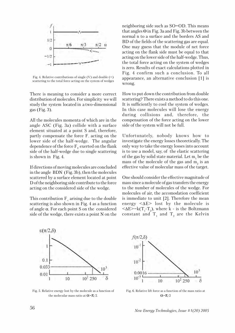
56New Energy Technologies, Issue #1(20) 2005
There is meaning to consider a more correctdistribution of molecules. For simplicity we willstudy the system located in a two�dimensionalgas (Fig. 3).
All the molecules momenta of which are in theangle ASC (Fig. 3a) collide with a surfaceelement situated at a point S and, therefore,partly compensate the force F^ acting on thelower side of the half�wedge. The angulardependence of the force FV exerted on the flankside of the half�wedge due to single scatteringis shown in Fig. 4.
If directions of moving molecules are concludedin the angle BDN (Fig. 3b), then the moleculesscattered by a surface element located at pointD of the neighboring side contribute to the forceacting on the considered side of the wedge.
This contribution F< arising due to the doublescattering is also shown in Fig. 4 as a functionof angle α. For each point S on the consideredside of the wedge, there exists a point N on the
neighboring side such as SO=OD. This meansthat angles Θ in Fig. 3a and Fig. 3b between thenormal n to a surface and the borders AS andBD of the fields of the scattering gas are equal.One may guess that the module of net forceacting on the flank side must be equal to thatacting on the lower side of the half�wedge. Thus,the total force acting on the system of wedgesis zero. Results of exact calculations plotted inFig. 4 confirm such a conclusion. To allappearance, an alternative conclusion [1] iswrong.
How to put down the contribution from doublescattering? There exists a method to do this one.It is sufficiently to cool the system of wedges.In this case molecules will lose the energyduring collisions and, therefore, thecompensation of the force acting on the lowerside of the system will not be full.
Unfortunately, nobody knows how toinvestigate the energy losses theoretically. Theonly way to take the energy losses into accountis to use a model, say, of the elastic scatteringof the gas by solid state material. Let m
1 be the
mass of the molecule of the gas and m2 is an
effective value of molecular mass of the target.
One should consider the effective magnitude ofmass since a molecule of gas transfers the energyto the number of molecules of the wedge. Formolecules of air, the accomodation coefficientis immediate to unit [2]. Therefore the meanenergy <∆E> lost by the molecule is<∆E>=k(T
1�T
2), where k � is the Boltzmann
constant and T1 and T
2 are the Kelvin
Fig. 4. Relative contributions of single (V) and double (<)scattering to the total force acting on the system of wedges
Fig. 5. Relative energy lost by the molecule as a function of
the molecular mass ratio at α=π/2.
Fig. 6. Relative lift force as a function of the mass ratio at
α=π/2

57New Energy Technologies, Issue #1(20) 2005
temperatures of the gas and the wedge,respectively. On the other side the value <∆E>is proportional to the temperature of the gas:<∆E>=ε(α,δ)kT
1, where δ=m
2/m
1. Thus,
ε(α,δ)=1�T2/T
1. There is meaning to consider
the best variant α=π/2. At α=π/2, thedependence ε(δ,α) is shown in Fig. 5. Supposethat T
1/T
2=0.967 that corresponds to room
temperature and T1�T
2=10oK. This gives δ≅250
(Fig. 5).
Now we are in a position to estimate the liftforce. The relative lift force as a function ofthe ratio δ at α=π/2 is shown in Fig. 6. In thiscase we have a perfectly reasonable value of thelift force f =0.0016 that corresponds to the liftforce 160 N acting on each m2 of the system.
In the meanwhile, this is only an idea though itreminds us somewhat a motion of an
asymmetrical body in the turbulent media [3].There may appear other arguments, dependingon a considered model, which prohibit thelevitation due to heating or cooling a body. Onemust be grateful for such arguments. Thesearguments will enable us to save energy andtime for searches of other principles oflevitation.
References
1. Beshok M.P. Energy from Air. // NewEnergy Technology. 2003. No 4(13). P. 31�32.2. Hurlbut F. On the Molecular Interactionsbetween Gases and Solids. // Dynamics ofManned Lifting Planetary Entry. New�York �London: Wiley. 1963.3. Blekhmann I.I. What Can Vibration Do?On Vibrational Mechanics and VibrationalTechnique. // Moscow: Nauka. 1988.
News
Having taken no profits from his publishingventure for a year has allowed Tom Beardento subsidize the reprinting of his ground�breaking book Energy from the Vacuum�Concepts & Principles.
Consequently he is pleased to announce asubstantial price reduction of this unique1000�page volume to $59, including U.S.domestic shipping (USD $69 for globalshipping). The student discount price forqualified students has also been slashed. Seeh t t p : / / w w w. c h e n i e r e . o r g / s a l e s /order_by_credit_card.htm
Cartons of 12 Energy from the Vacuum books,also individually shrink�wrapped, are nowavailable for the incredible low price of $350,including U.S. shipping. These make greatgifts to politicians, scientists, teachers,libraries etc. Contact us for global shippingprice on bulk orders.
Energy from the Vacuum is the world's firstand only book to correct many of the errorsand omissions in today's science, removingtheoretical impediments to the extraction offree energy from the vacuum. It also catalogsthe pioneering efforts of many of theinventors who have indeed extracted this freeenergy over the years. Over forty differentmethodologies are described in detail, someof them replicable at the high school level.
Thanks also to all you supporters andvolunteers who have helped make thispossible.
Regards,
Tony CraddockDirector
Cheniere Press/ The Tom Bearden Websitewww.cheniere.org

58New Energy Technologies, Issue #1(20) 2005
According to statistical analysis of peaks of fullabsorption and gamma radiation’s amplitude,experimental and theoretical confirmations ofrotating objects’ remote influence on readings ofsemiconductor spectral equipment. It is shownthat value of statistical distribution’s shiftdepends on speed changing of collection ofsemiconductor’s charges. A physical fieldgenerated during rotation, which is not connectedwith electromagnetic component, influences onspeed of collection.
1. Introduction
First experimental research of rotating liquidwas made by the author in 1991 [1]. It wascarried out in semiconductor spectrometryduring relative measuring of two modes ofoperation (with rotation and without it) andallowed discovering the effect consisting insquare’s diminution of gamma full absorption’speak. In 1995, published experimental resultsof various researchers confirmed the remoteinfluence of gyroscopic motors on readings ofcounter tube and scintillation counter duringmeasuring of natural radioactivity [2].
The aftereffect was discovered, i.e. influenceexisted after motors had been turned off. Duringfurther research, the following rules were foundout: first, during rotation, the peak’sdistribution moves towards decrease ofintensity; second, under certain conditions, atype of distribution changes (duplets, “tails”appear); third, during rotation, distributionshift of the peak’s focus (gamma�quantumenergy) occurs including increasing as well asdiminution of the signal’s amplitude [3, 4].
Analysis of statistical results allowed findingout that a system “radioactive source –semiconductor detector” can be used as a sensor
of the physical field’s potential generated byrotating objects. This statement is based onshifting of statistical distribution of peak andamplitude’s square towards diminution andmeasuring with rotation and without it.Quantity of shift depends both onelectromagnetic interference andnonelectromagnetic component of the physicalfield. This work includes experimental andtheoretical researches showing theelectromagnetic component’s influence on timeof charge collection of semiconductor detector.
2. Description of experiments
In this chapter, a plan of the experiment isshown and possible sources of noise and theirinfluence on experimental results aredetermined.
REMOTE INFLUENCE OF ROTATINGREMOTE INFLUENCE OF ROTATINGREMOTE INFLUENCE OF ROTATINGREMOTE INFLUENCE OF ROTATINGREMOTE INFLUENCE OF ROTATINGOBJECTS ON SEMICONDUCTOROBJECTS ON SEMICONDUCTOROBJECTS ON SEMICONDUCTOROBJECTS ON SEMICONDUCTOROBJECTS ON SEMICONDUCTOR
GAMMA-RAY DETECTORGAMMA-RAY DETECTORGAMMA-RAY DETECTORGAMMA-RAY DETECTORGAMMA-RAY DETECTOR
I.A.MelnikI.A.MelnikI.A.MelnikI.A.MelnikI.A.MelnikE-mail: [email protected]: [email protected]: [email protected]: [email protected]: [email protected]
Fig. 1. Detailed scheme of the experiment
1 � semiconductor; 2 � radioactive source; 3 � beaker withliquid; 4 � electronic motor; 5 � coil with twisted filament

59New Energy Technologies, Issue #1(20) 2005
On Fig. 1, a semiconductor detector (1), agamma�ray source (2) and a steel beaker withliquid (3) located on the one line, which isperpendicular to the floor, are shown. Vortexrotation of liquid was made by blades at a motoraxis (4).
Steel discs (without the beaker, of course) werealso used as rotating objects. A 250�wattcommutator motor was attached to a post. Themotor axis rotating with angular velocities 2100and 6000 revolutions per minute (r/m) waslocated above radioactive isotope source atdistances determined by the experiment’sconditions. Sources (Cs137, Co60 etc.) wereattached at props of different heights from thesemiconductor detector (SCD). Distance fromthe radioactive source to the detector wasdetermined so that peak’s square was S~8000�11000 pulses during not more than a minute.In case there was no the standard emissionsource of the previously chosen isotope, thestudied element was irradiated by Tomskresearch nuclear pile according to the methodof neutron� activation analysis. Size of thesource did not exceed 0.25 cm2.
The semiconductor Ge(Li)�detector, apreamplifier, an amplifier, and an analyzer wereused as measurement equipment. The fullabsorption peak’s square, which is proportionalto quantity of registered quanta, and peak’scentre of gravity, which is proportional tophoton energy, from various sources ofradioactive energy were measured. Data on theanalyzed spectrum was processed by "Search"program developed in Dubna. Width of energyresolution did not exceed 3 kilo�electron�volt(keV). During a measuring hour shift of thepeak’s centre of gravity did not exceed 0.5 keV.
The peak was measured during two operationmodes: motor working and stopped. Rotationwas carried out both clockwise andanticlockwise. During the experiment, qualityof measuring was carried out when gatheringspectrum. Quality was determined by thefollowing characteristics: first, due to significantchanging of voltage or leakage currentappearance (caused by humidity increase), thepeak’s width increases, i.e. energy resolutionincreases. Hence, accuracy of the peak’s squaredetermination goes down considerably.
Implementation factors (temperature andvoltage changes) did not influence the peak’ssquare. The influence is possible only providedthat there is drift of a few units (keV) duringspectrum gathering.
Second, being typically Gaussian, the peak ischaracterized by the gravity centre (the firstderivative from the function, the approximatingpeak, turns into zero), i.e. by its place on energyscale. During each measuring, gravity centre ofthe peak was registered.
Third, as comparative analysis was carried outfor readings of two operation modes, in orderto avoid a systematic mistake (drift ofgravitation centre), mode of the experimentchanged after each ten measurements.Measuring was carried out during twooperation modes alternately. Statisticaldistribution of gravity centre in rotating modeE
rot regarding gravity centre in nonrotating
mode Est was studied. It allowed exclusion of
drift value.
Forth, the post of the electric motor wasattached to a massive steel table (~60 kg) whileDewar bottle (31 kg) was on a soft traypreventing transmission of small vibrationsfrom the electric motor to the detector.
It was only impossible to prevent influence ofelectromagnetic fields of the electromotor,generation of signal under discrimination lowerlevel. It could lead to increase of total dead timeof the registered equipment and diminish squareof friendly signal’s peak. Theoretical analysis ofthis situation will be shown below.
Statistical analysis of experimental results wascarried out with 95%�credibility value.
3. Experimental results and their analysis
Experimental results connected with changing ofrotation direction (clockwise and anticlockwise,view from above) are shown on Fig. 2. The steeldisk (90 mm in diameter, 5 mm thick) attachedto the motor axis rotates with angular velocityof 6,000 r/m. During each operating mode, 60measurements of the peak’s square were carriedout by isotope Cs137’s energy of 661.6 keV.

60New Energy Technologies, Issue #1(20) 2005
Distance between the disk and the radioactivesource was 97 mm; between the source and thedetector – 20 mm. Average measure of the peak’ssquare in nonrotating mode is S
st=11734 pulses,
standard mistake is σ=46.8; in the anticlockwiserotation mode it is S
pr=10375 pulses, σ=25.5,
while during clockwise rotation it is Spo
=8693pulses, σ=83.5. Univariate analysis regardingstatic mode has shown that Fisher�criteria areF
stpo=1009 and F
stpr=649 while critical value is
Fst
po=1009.
Due to the fact that distribution shift depends onrotation direction, we can suggest that influencefield has spatial orientation (left or right) and,accordingly, orthonormal matter screening thefield influences distribution shift. Apolyethylene coil with diameter of 70 mm andheight of 20 mm consisting of right�twistedfosta nylon filament was used as a screenbetween the motor axle and emission source(Fig. 1).
Relative distribution of peaks of two samplingswas investigated: in clockwise rotation modeand in nonrotating mode Ppo/Pst. The followingresults were obtained: average value of relativedistribution without the screen is Srpo=0.9739rel. units, σ=0.0040, Fisher�criterion isFpo
st=91.2; with the screen, Srpo=0.9807 rel.units, σ=0.0092, Fpo
st=4.5. Using left�twistedfilament, influence field passes through the coilonly when the motor axle rotates clockwisewhile, using right�twisted filament, it happensmostly during anticlockwise rotation. Thus, thecoil is an absorbent of influence field. This showsnonelectromagnetic component of the physicalfield.
During further experiments, three steel diskshafted alternately on the motor axle withdiameter of 90 mm and thickness of 5 mm wereused as a generator of influence field. Distancebetween disks and isotope Cs137 was ~100 m.Steel grade was 40XA. The first disc (#1) wasmade of new steel, which had not been used inproduction; the second (#2) and the third (#3)ones were made of a material actively usedduring a year.
Thus, the two last discs differ from the first onein certain accumulated metal fatigue, i.e. theyhave many inner defects. Using 15�mm�distancebetween the isotope source and the detector, thefollowing results were obtained in the staticmode: average peak’s square S
st=12248 pulses,
σ=38, time of spectrum gathering (live) t=35sec. later, measurements in rotation modes wereimplemented. A difference (shift) in averagevalues of the peak ∆S
rotn=S
st�S
rotn where “n”
means the number of the studied disk. Thefollowing results were got: ∆S
pr1=4207 pulses,
σ=235; ∆Spo
1=5337 pulses, σ=196; ∆Spr
2=1146pulses, σ=64; ∆S
po2=423 pulses, σ=42; ∆S
pr3=722
pulses, σ=129; ∆Spo
3=789 pulses, σ=44. Shift ofaverage values of the peak’s square and itsdispersion depends on condition of internalstructure of the rotating object.
Studying influence of the rotating matter (liquid)on type of statistical distribution of the peak’ssquare, an effect of non�Poisson distributionretention after the motor was turned off wasdiscovered. Angular velocity of the axle was
Fig. 2.Statistical distribution of full absorption peaks duringmeasuting of photon emittio. 1 � nonrotating mode; 2 �
clockwise rotation mode; 3 �anticlockwise rotation mode.
Fig. 3. Statistical distribution of peaks of full absorptionduring measuring of cesium photon emittion's intensity in
nonrotating mode. 1 � after the motor is turned off; 2 � in a daysince turning�off; 3 � in five days since turning off.

61New Energy Technologies, Issue #1(20) 2005
2100 rev/min; the beaker with liquid waslocated above cesium isotope at distance of 10mm. The peak was measured during variousperiods of time (live time of measuring ist
g=90c); right after the rotating motor was
turned off (t=0); in 24 hours since turning off(t=1) and in 5 days since turning off (t=5) (Fig.3). A tendency of distribution shift towardsintensity diminution and changing ofdistribution type was noticed. A month sincethe source of rotation was turned off, statisticaldistribution becomes of a type close to normaldistribution besides a small “tail”. Varianceanalysis of distributions obtained in momentsof time =0; t=1) and (t=0; t=5) has shown thefollowing Fisher�criteria: F
0�1=4.3 and F
0�5=13.8
while Fk=3.9. Aftereffect means that there is the
physical field in metastable state.
In Table 1, the measuring results of some typesof energy (the second column) under influenceof the field’s rotation on various isotopes areshown. Measuring was carried out duringliquid’s rotation with angular velocity of 2100rev/min (Rot) or during the nonrotating mode(St). Type of statistical distribution of photonsQ
p’s intensity is marked by the following letters:
type in the form of duplet is D, in the tripletform is T, the type close to the normal (Poisson)one is N. Average values of the peak’s square S,standard mistake σ and difference betweenextreme distributions in the multiple ∆
p is
shown in columns 6 – 8. In the next column,letter “L” marks length of a “tail” of impulses’
distribution directed from the medium intensitytowards its diminution. In the last four columnsthe same values are given for relative energy.Distribution of relations E
rot/E
st was studied.
ME marks a median of statistical distribution of
relative energy.
As an example, distribution of peaks andamplitude of pulses during zinc isotope’smeasuring (in the rotating mode) is shown onFig. 4. Reverse correlation of amplitude andpeak’s square with coefficient �0.54 is shown.Resonance effects both for peak’s square andamplitude of pulses took place only during zincisotope’s measuring.
In order to study influence of the detectorcharging on quantity of the peak’s square shiftduring relative measuring, 50 measurements ofcesium�137 during different modes was carriedout for distances of 1; 2; 4 cm from the detectorwhile the distance from the beaker’s bottom wasunchanged. In this case, changing of chargingcharacteristics of the detector happens. Relativedistribution P
rot /S
st were studied. P
rot –
selective values of the peak’s square in therotating mode, S
st – average value of the peak’s
square sampling in the nonrotating mode. Thefollowing results obtained: average value ofrelative distribution of the sampling in therotating mode for a distance of 1 cm wasSr
1=0.8591, σ=0.0085; for a distance of 2 cm
Sr2=0.9707, σ=0.0019; for a distance of 4 cm
Sr4=0.9869 σ=0.0059.
Iso� Е, Quant. Ope Qp S, σ, ∆p, L, QE ∆E, ME σE,
tope (keV) of rat. (pulse) (pulse) (pulse) (pulse) (keV) (rel units) x10�6
mesur. mode (rel.units)
Zn65 1115 350 St D 11326 11.5 250 � N � 1.000016 3.7 Rot D 10899 42.9 200 3400
Rb86 1077 150 St D 10500 16.4 250 � T 1076.91� 0.999984 5.7 Rot D 9959 89.7 300 4500 1077.08
Am241 59 100 St N 11972 17.6 � � N � 1.000051 68.0 Rot D 11839 24.1 100 540
Cs137 661.6 426 St D 11018 11.7 500 � N � 0.999978 7.1 Rot D 11018 12.8 400 1000
Na22 1274 100 St N 10352 19.0 � � N � 1.000013 10.0 Rot N 10286 14.0 � �
Sb122 603 150 St D 10091 14.7 150 � N � 0.999981 9.7 Rot D 10064 15.0 200 �
Eu152 122 150 St D 10266 13.2 150 � D 122� 1.000053 19.5 Rot D 10247 12.4 150 � 122.02
Co60 1332 150 St N 10938 27.3 � � D 1331.9� 0.999950 8.9 Rot N 8500 87.9 � 2450 1332.18
Table #1

62New Energy Technologies, Issue #1(20) 2005
Univariate analysis for two types of distributiongave criteria F1�4=150.9 and F2�4=6.6 whileFk=3.9. Hence, the more discharging of thedetector, the more difference in the peak’ssquare distribution during different operationmodes, though relative energy (amplitude)distribution for the two types does not change.
Investigating dependence of shift value ofstatistical distribution from spatial location ofthe system “source � detector” regarding theelectric motor along the motor axle, changingof this value was noticed up to completecoincidence of measuring distributions duringrotating and nonrotating modes. Within thelimits of 10�30 mm from the rotating object(rotating speed of liquid is 2100 rev/min),maximal value of shift in the peak distributionswas found.
Analysis of implementation spectrum of cesiumisotope measuring has revealed one more peakwith average energy of 669.6 keV. Its rate (i) inthe sampling is different for various modes andgeometries of measuring. We name it a peak�double – Sd. During the first measuring innonrotating mode, it was measured thatSd1
st=874 pulses, σ=54.1, i=15%. Accordingly,we determine average square of the peak�doubletaking into account rate of implementationspectra in the sampling, i.e. sd=Sdi/100, wheresd1
st=131 pulses. During anticlockwise rotation,Sd1
pr=1197 pulses, σ=15.5, i=76%, sd1pr=917
pulses. Measuring another cesium source, thefollowing values were obtained: Sd2
st=904pulses, σ=34.0, i=13%, sd2
st=120 pulses,
Sd2pr=1237 pulses, σ=19.6, i=93%, sd2
pr=1154pulses. Thus, significant increase of the peak�double’s square takes place with regard to thenonrotating mode. Difference in the peak�double energy value (during second measuring)comparing Pr and St modes is ∆Est
pr=0.87 keVwhile σpr=0.04 keV. Increase of the detector’scharging also increases the peak�double, forexample, during simultaneous measuring of twocesium isotopes the following valuesdetermined: sd3
st=1442 pulses, sd3pr=1869 pulses.
In order to study the peak�double’s behaviordepending on energy of the registered photons,along with cesium peaks Co60 with energy of1173 keV and 1332 keV and, accordingly, peaks’squares with energy of 1183 keV and 1343 keVwere measured. The experiment results areregistered in table #2. In this case, energy ofregistered emission and detector chargingincrease. Comparing two cesium experiments,changing dynamics of peaks’ squares fordifferent operating modes considerably differs.When the experiment is repeated (the secondmeasuring) with cobalt, the difference of thecesium peak�double energy is ∆Est
pr=1.37 keV,σpr =0.087 keV.
Table #2
S661 S1173 S1332 sd669 sd
1183 sd1343
St 10123 9505 8886 1829 120 0Pr 5536 4742 3988 687 710 522Po 7085 6386 5769 1331 1543 1173
Fig. 4. Dependency of peak's square (1) and relative pulse amplitude (2) on number of measuring, during zinc isotope measuring in rotating mode

63New Energy Technologies, Issue #1(20) 2005
Measuring of implementation spectrum forclockwise and anticlockwise rotation wascarried out on different days. Then correlationdependences of peaks and peak�doubles’samplings in each modes were studied. Thecorrelation coefficients obtained wereregistered in Table 3. In order to diminish sizeof the table, all columns having correlationcoefficients less than 0.6 were deleted. Thefollowing rules are discovered:
1. Correlation takes place only in rotatingmodes;2. Correlation of selected values can occur inindependent experiments;3. Correlation is positive between peaks andpeak�doubles.
Later, 24 samplings of cesium peaks’ squares,which were got in different times and variousgeometries, were studied while the object wascorrelation of sampling values. Twelvecorrelation coefficients from 0.6 to 0.96 weregained including both positive and negativecoefficients. Correlation is mostly negativeamong sampling values of the peak (661.6 keV)and the peak�double (669.6 keV).
During experiment, influence of rotation ondifferent radioactive isotopes in various
geometrical conditions (rotation speedchanging, measuring geometry, presence orabsence of liquid) was studied. Dependence ofmedians M
S(M
E) of the according distributions
Erot
/Est
and S*rot
/S*st
, where S* is samplingvalues of the peak’s square. Almost all values ofthese medians are less than 1. The followingdependence of medians ∆M
E(∆M
S) was built:
∆MS=|1�S*
rot/S*
st| and ∆M
E=|1�E
rot/E
st|Eγ, (1)
Accordingly, Eγ�energy of the registeringphoton is in keV (Fig. 5). Areas of “prohibited”zones appear on the diagram and change ofsignal’s amplitude distribution is connectedwith change of intensity distribution.
4. Theoretical analysis of results
In this chapter, theoretical basis of a possiblereaction of the semiconductor detector toremote influence of rotating objects generatingthe physical field without the electromagneticcomponent is given.
It is know that impulse’s amplitude in maximumpoint at the exit of the amplifier is determinedby the expression U=U
0[1�exp(�t/t
n)], where t
is a measuring moment at maximal amplitude
Pr� Pr� Pr� Pr� Po� Po� Pr� Po�1173 1332 1183 1343 1173 1332 661 661
Pr�1173 1Pr�1332 0.85 1Pr�1183 0.72 0.49 1Pr�1343 0.82 0.90 0.46 1St�1173 �0.06 �0.02 0.25 �0.18St�1332 0.03 �0.05 0.31 �0.17Po�1173 �0.46 �0.43 �0.43 �0.43 1Po�1332 �0.58 �0.58 �0.49 �0.46 0.85 1Po�1183 �0.11 0.03 �0.47 0.44 0.61 0.37Po�1343 �0.59 �0.52 �0.35 �0.74 0.49 0.40St�661 0.09 0.05 0.33 �0.38 �0.21 �0.18Pr�661 0.89 0.87 0.66 0.83 �0.46 �0.61 1Po�661 �0.61 �0.57 �0.49 �0.61 0.86 0.94 �0.65 1St�669 �0.24 �0.22 �0.12 �0.39 0.04 0.01 �0.29 0.10Po�669 �0.46 �0.44 �0.33 �0.54 0.80 0.74 �0.42 0.76Pr�669 0.47 0.48 0.28 0.70 �0.26 �0.33 0.62 �0.36
Table #3

64New Energy Technologies, Issue #1(20) 2005
of output signal; tn is a coefficient of RC�chaintime; input amplitude is U0=Qtn/tcob [5, 6].Using the expression (1) and knowing thatU0~Eγ, we can write Est=Eγ[1�exp(�t/t'n)]. Dueto the fact that analysis of experimental datawas carried out in relative values, we can use anassumption that Est�const and Erot=Eγ[1�exp(�t/tn)]. After small transformations, theexpression (1) is the following
∆ME=M[exp(�t/tn)+B�1], (2)where M=Eγ/B, B=1�exp(�t/t'n) – const.
Let’s pay attention to the time coefficient,which is the product of resistance and loadcapacitance of the detector tn=RnCn. AmplitudeU0~tn and average dead time of amplitudedigital transformer (ADT) is tm~U, so we havetn=ptm, where p is a coefficient of ratability[pulse] because of tm. Sst value is a peak’s squareif tm=0. Using the expression Srot=Sst(1�nΣtm),where nΣ is a total speed of the analyzer’scalculation over all canals, we determine theloading time tn=(p/n)[1�Srot/Sst]. Puttingdependence of the loading time in the equation(2), we will get an equation of pulse amplitudechanging in dependence on the peak’s squarechanging
∆ME=M[exp{�tn/(p[1�Srot/Sst])}+B�1] (3).
If we put in the equation (3) the experimentaldata ∆MS and find three values � tn/p=1.73; 2.1;2.43, we will get theoretical dependences shownon Fig. 5.
It is necessary to find out how theelectromagnetic field generated by the electric
motor can influence amplitude and square of thefriendly signal’s peak. We know that capacityC
w and resistance R
w are attached to the input
stage of the amplifier. So, Cn=C
d+C
w (a) and
Rn=R
dR'
w/(R
d+R'
w) (b), where R'
w= R
wR
wc/
(Rw+R
wc). Having a variable component of
current, capacitance Rwc
=1/ωCw, where ω� is a
cycling frequency of alternating currentgenerated, occurs. Thus, not taking into accountvariable component influence on the detector’scapacity (i.e., C
n=C
w), we have
tn=R
dR
wC
w/(R
dR
wC
wω+R
d+R
w) (4)
putting tm=t
n/p in the expression of the peak’s
square, we get
Srot
=Sst(1�nt
n/p) (5)
In this case, we can suggest that total speed ofthe analyzer’s calculation will be increased bythe impulse component generated by themotor’s collector, jw, where w is rotationfrequency and j is ratability coefficient, i.e.n=nΣ+jw. Hence, in case ω and w increase, thepeak’s square and impulse amplitudediminishes, due to U
0~t
n.
Value jump tn/p seems to be connected withquantum effect in the semiconductor detector,which is caused by the generatedmulticomponent physical field influencinggroup speed of charge and changing t
cob
(apparently p~ tcob
). Below, we will describeinfluencing degree of electromagneticcomponent.
Fig. 5. Dependence of difference of energy distributionmedians (amplitude) on difference of peak's square
distribution medians during rotation regarding nonrotatingmode; theoretical curves, 1�tn/p=1.73, 2�tn/p=2.1,
3�tn/p=2.43
Fig. 6. Dependencies of increment energy (1) and relative peak'ssquare difference on relative charge speed

65New Energy Technologies, Issue #1(20) 2005
Germanium�lithium generator is kept at theliquid nitrogen temperature. Acceptor dopantof lithium creates p�i�n hole conduction, somaximal collection time is connected mostlywith speed of hole’s diffusion, i.e. t
cob=d/v, where
d is a width of the barrier region; v is an average(group) speed of holes [7]. It is known thatd=[χ(U
c�U
1)/(2πeN
a)]: χ is a dielectric
constant, Uc is a bias, U
1=0.3В for germanium,
Na is a concentration of acceptors. At the same
time, charging speed v~[Uc]1/2, and we can
write, accordingly, that tcob
~ [Uc�U
1]1/2/[U
c]1/2,
and if Uc=1500 V, we can make a conclusion that
collection time does not depend on changing ofbias.
Meanwhile, loading time is proportional to thedetector’s capacity. Due to C
d=1.1χs/(4πd), a
proportion tn~1/[U
c]1/2 forms. Obtained
dependences show that the electrical fieldinfluences only loading time but not t
cob. In
connection with this, it is necessary to clear aphysical meaning of Θx=tn/p value (x=1; 2; 3).We determine the dependency Θ
x(t
cob) using the
constant electrical component ω�const. Due tothe fact that t
m~U и U
0~t
n and using the formula
of impulse amplitude, we can make thefollowing expression At
m=(Qt
n/t
cob)[1�exp(�t/
tn)], where A [pulse x V/c] and Q [V] are
constants. If Q/A=T�const, we can write usingthe expression р=(t
cobA/Q)/[1�exp(�t/t
n)]
while Ttn=υ�const that
Θx(t
cob)= (υ/t
cob) [1�exp(�t/t
n)]. (6)
An equation shows that, measuring relativeshift of the peak’s square of gamma�quanta ofdifferent energies emitted by the sameradioactive source (for example, Co), the peak’sshift value can be different for each energy types(different t
cob). Experimental results confirm
this conclusion. For instance, duringsimultaneous measuring of Со (1332 and 1173keV) and Cs (661.6 keV), points ofexperimental values ∆М
E(∆М
S) of energy of
1332 and 661.6 keV was located on curve #2while a point of 1773�keV�energy was locatedon curve #1 (Fig. 5). The most of experimentalpoints of 1773�keV�energy are located on curve#1 while points of 661.6�keV�energy aredistributed evenly on three curves. Thus, it isnecessary to find out a cause of jump of thecharge collection time.
Collection of nonequilibrium charges in thesemiconductor detector happens in thefollowing way. After photoeffect, electron getsenergy sufficient for cascade process of balancedcharges’ dislodging. Most electrons go toacceptor. Accordingly, normal band is zone ofp�type conductivity. In this research, collectiontime depends only on diffusion speed of holes.Changing of the collection time influences boththe peak’s square and input amplitude. It isconfirmed by following arguments. If ω=0,impulse amplitude depends on the ratio t
n /t
cob.
Putting equations (a), (b) and Rd=λt
cob (λ is a
constant while Eγ�const) in the expression (4)and lightly modifying it as the dependencet
n(t
cob), we get t
n(t
cob)=R
wC
wλt
cob /(λt
cob+R
w).
Due to λtcob
<<Rw (λt
cob~105 ohm; R
w~108 ohm),
the expression can be changed ast
n(t
cob)≅C
wλt
cob. In case Q=q/C
w, the input
impulse amplitude is U0≅qλ. The less t
cob, the
more the expression (1�exp(�t/tn)) and,
accordingly, the more impulse amplitude.Putting the obtained dependence t
n(t
cob) in the
equation (5), we calculate S(tcob
)≅S0{1�G[1�
exp(�t/Cwλt
cob)]}, where G=nTλC
w. Thus,
increasing of the collection time diminishes thepeak’s square (Fig. 4).
Group speed of a hole depends on energy levelof normal band, that is expressed as v=dE/dk(2π/h), where k is a phase vector and h isPlanck's constant. In scalar form, E=h2k2/(8π2m) close to normal band’s borders. Effectivemass of m�hole depends on state of energy level,its width and charge motion’s direction in acrystal. Correspondingly, reciprocal of effectivemass is determined as double tensor. It is knownthat energy is maximal close to normal band’slimit if k=0. In case energy level reaches bordersof Brillouin zone of the according k�field k=π/a; 2π/а …, a band gap forms, due to chargediffraction on potential of the lattice. If k�vectorincreases, energy jumps according to the level.Using the expression (6), in case tn�const, wecan write a following proportion
Θx(t
cob)~1/ t
cob~v~dE/dk~k/m.
Thus, values of the peak’s square shift andamplitude are directly connected with changingof energy level and phase vector of thesemiconductor’s charges.
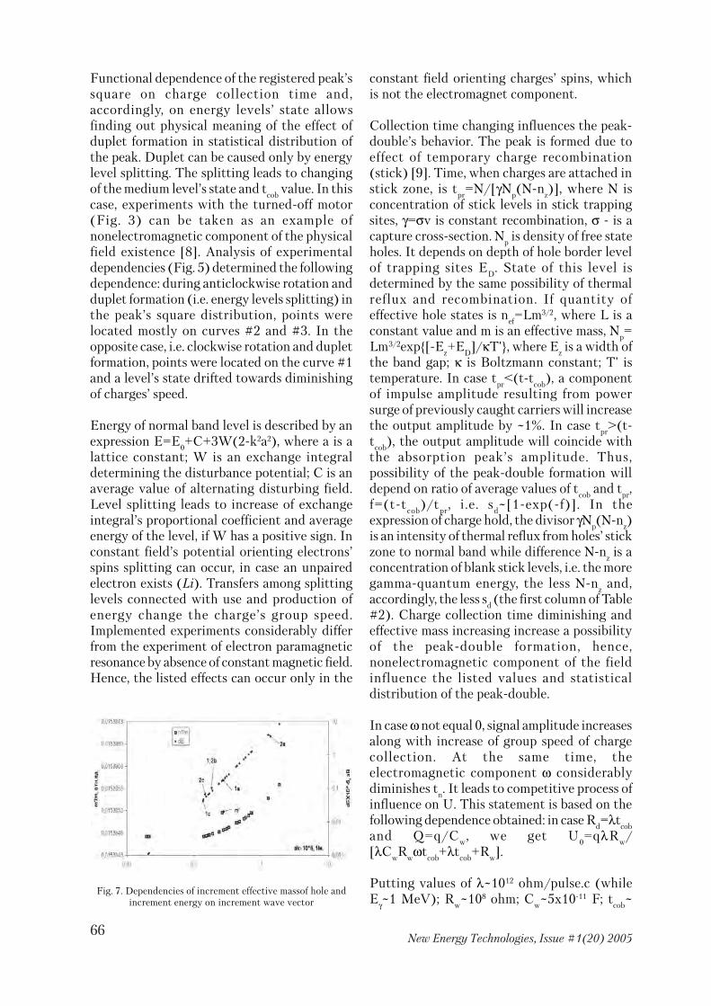
66New Energy Technologies, Issue #1(20) 2005
Functional dependence of the registered peak’ssquare on charge collection time and,accordingly, on energy levels’ state allowsfinding out physical meaning of the effect ofduplet formation in statistical distribution ofthe peak. Duplet can be caused only by energylevel splitting. The splitting leads to changingof the medium level’s state and t
cob value. In this
case, experiments with the turned�off motor(Fig. 3) can be taken as an example ofnonelectromagnetic component of the physicalfield existence [8]. Analysis of experimentaldependencies (Fig. 5) determined the followingdependence: during anticlockwise rotation andduplet formation (i.e. energy levels splitting) inthe peak’s square distribution, points werelocated mostly on curves #2 and #3. In theopposite case, i.e. clockwise rotation and dupletformation, points were located on the curve #1and a level’s state drifted towards diminishingof charges’ speed.
Energy of normal band level is described by anexpression E=E
0+C+3W(2�k2a2), where a is a
lattice constant; W is an exchange integraldetermining the disturbance potential; C is anaverage value of alternating disturbing field.Level splitting leads to increase of exchangeintegral’s proportional coefficient and averageenergy of the level, if W has a positive sign. Inconstant field’s potential orienting electrons’spins splitting can occur, in case an unpairedelectron exists (Li). Transfers among splittinglevels connected with use and production ofenergy change the charge’s group speed.Implemented experiments considerably differfrom the experiment of electron paramagneticresonance by absence of constant magnetic field.Hence, the listed effects can occur only in the
constant field orienting charges’ spins, whichis not the electromagnet component.
Collection time changing influences the peak�double’s behavior. The peak is formed due toeffect of temporary charge recombination(stick) [9]. Time, when charges are attached instick zone, is t
pr=N/[γN
p(N�n
z)], where N is
concentration of stick levels in stick trappingsites, γ=σv is constant recombination, σ � is acapture cross�section. N
p is density of free state
holes. It depends on depth of hole border levelof trapping sites E
D. State of this level is
determined by the same possibility of thermalreflux and recombination. If quantity ofeffective hole states is n
ef=Lm3/2, where L is a
constant value and m is an effective mass, Np=
Lm3/2exp{[�Ez+E
D]/κT'}, where E
z is a width of
the band gap; κ is Boltzmann constant; T' istemperature. In case t
pr<(t�t
cob), a component
of impulse amplitude resulting from powersurge of previously caught carriers will increasethe output amplitude by ~1%. In case t
pr>(t�
tcob
), the output amplitude will coincide withthe absorption peak’s amplitude. Thus,possibility of the peak�double formation willdepend on ratio of average values of t
cob and t
pr,
f=(t�tcob
)/tpr
, i.e. sd~[1�exp(�f)]. In the
expression of charge hold, the divisor γNp(N�n
z)
is an intensity of thermal reflux from holes’ stickzone to normal band while difference N�n
z is a
concentration of blank stick levels, i.e. the moregamma�quantum energy, the less N�n
z and,
accordingly, the less sd (the first column of Table
#2). Charge collection time diminishing andeffective mass increasing increase a possibilityof the peak�double formation, hence,nonelectromagnetic component of the fieldinfluence the listed values and statisticaldistribution of the peak�double.
In case ω not equal 0, signal amplitude increasesalong with increase of group speed of chargecollection. At the same time, theelectromagnetic component ω considerablydiminishes t
n. It leads to competitive process of
influence on U. This statement is based on thefollowing dependence obtained: in case R
d=λt
cob
and Q=q/Cw
, we get U0=qλR
w/
[λCwR
wωt
cob+λt
cob+R
w].
Putting values of λ~1012 ohm/pulse.c (whileEγ~1 MeV); R
w~108 ohm; C
w~5x10�11 F; t
cob~
Fig. 7. Dependencies of increment effective massof hole andincrement energy on increment wave vector

67New Energy Technologies, Issue #1(20) 2005
10�7 c, we can notice that tcob
influences theoutput amplitude in a case constant value of ωis about a few hundreds hertz. At firstapproximation, a frequency of ω will coincidewith the frequency of voltage harmonicsgenerated by the electric motor. Hence, ω≅wxl,where w is angular velocity of rotor, x is anumber of grooves per pole and collector’sphase, 1 is a quantity of phases. Changing of thepeak’s square depends on changing of values ofn and t
cob, so the more degree of influence by
any of the field’s component, the more shift ofthe peak’s square distribution towardsdiminishing. Due to this, in case theelectromagnetic component is constant andreverberatory interacts with a moving charge,the relationship U(S) should be inversenegative (Fig. 4).
Obtained formulas (2)�(6) and experimentalresults (S
rot, S
st, E
rot, E
st, n, ω etc.) allowed
approximately determining charge collectiontime before rotation t
c0 and during rotation t
cob.
In case a barrier region’s width is d=1.7 cm, wecould calculate speed v
c=d/t
cob and charge
acceleration r'=∆vc/∆t, where ∆t=t
c0�t
cob and
∆vc=d/t
cob�d/t
c0. In case external electric field ε
exists permanently in the semiconductor, a forceεq=rm influences a charge q. Due to the fact thatcharge speed increases during rotation, we canwrite an expression (m�m')(r+r')=εq. Hence,m'=m�εq/(r+r'), where r is acceleration of holesin nonelectromagnetic component absence.Average acceleration of heavy and high mobilityholes is r≅1x10¹⁷ m/sec2, and then we calculateincrement of wave vector ∆k=(2πm'∆v
c/h) and
energy increment ∆E= h2∆k2/(8π2m').
Dependencies of the relative peak’s squaredifference s=1�S
rot/S
st and increment energy on
the relative speed are made: – v=vc/v
c0 (Fig.6).
Step decrease of ∆E value can be seen on thediagram while the relative charge speed isv
1=1.03 rel/units. Thus, from the moment v
1,
the more charge energy, the less peak’s squareS
rot, while before the moment v
1 s<0.22 and does
not depend on energy.
Now we make dependencies ∆E(∆k) and m'/m
0(∆k) of the so called increment ∆k – space
(Fig. 7). On the diagram, the value of incrementmass (m') deviated from the obtained curve.The analysis showed that this result had been
got during rotor’s rotation with speed of 2100rev/min.
In case gamma quanta of different energies aremeasured simultaneously, values of n and ω areconstants. Due to this, considering influence oncharges’ spins in the semiconductor, t
cob�time for
every gamma quantum can be different. We willdescribe two experiments as examples. Theywere carried out with angular velocity ofclockwise rotation of 6,000 rev/min, withoutthe steel beaker (named 1a, 1b, 1c) and with theempty one (named 2a, 2b, 2c). In this case,simultaneous measuring of cobalt (theregistered energy was marked (a=1332 keV andb=1173 keV) and cesium (c=661.6 keV). It canbe noticed that the beaker used in theexperiment influences the charge energy onlyin points a and c. This effect shows increase ofenergy levels at 2a and 2c points relative to the1a and 1c experiment provided by possiblesplitting of the given energy level. Statisticalanalysis of the peak’s square distribution (S
rot)
helped finding out the following dependence:at 1c point, the distribution is normal; at 2c, 1a,1b, 2b points they have a duplet form while, at2a point, the distribution is triplet. Thus, energyscale shift towards increase is straightlyconnected with increase of multipledistributions and, accordingly, with energy levelsplitting (proportional coefficient of theexchange integral increases). It is interestingthat the a/c≅2 relation can possibly cause thesynchronal shift of energy scale.
Analysis of theoretical and experimental resultshas shown the following rule: in case the angularspeed of the motor axle is 2,100 rev/min, theobtained results were located in the v<v
1 area;
in case in case the angular speed of the motoraxle is 6,000 rev/min, they were located in theright area (Fig. 6). Influence of theelectromagnetic component duringexperiments was relevant. In case ω=0, arelevant signal amplitude is E
rot/E
st>1. Actually,
almost all values are Erot
/Est
<1. At the sametime, the electromagnetic component cannotcontribute to energy levels’ splitting duringthese experiments. The calculation showed thata frequency of electronic resonance, being ν, isν~106 hertz during cesium gamma quantaregistration after the motor is turned off.Maximal frequency of field absorbed by a

68New Energy Technologies, Issue #1(20) 2005
moving charge of the semiconductor was ~1010
hertz during measuring in the rotating mode.We know that radiointerference havingfrequency spectrum of 105�108 hertz can begenerated at clips of collectors, although thisdoes not explain the mentioned above effects[10]. In electron spin resonance, electric fieldfrequency not more that ν~1010 are used but itis ~1 weber/m2 in strong magnetic fields. Tht’swhy we describe a hypothetical field explainingall the effects.
5.Conclusion
Some experiments, such as memory effect(measuring after liquid stops rotating);information transfer about a rotating object’sstate (rotation of discs) etc. confirmingexistence of nonelectromagnetic influence oncharge energy of the semiconductor allowsuggesting that the described interactionbelongs to torsion field.
In works of A.V. Bagrov etc. [11] equations ofsmall relativistic particle’s motion in externaltorsion field are obtained. They showdependence of kinetic energy of the particle onthe nonelectromagnetic component. Anexpression for Hamiltonian is determinedforecasting torsion field’s influence on energylevels. In case the component of pseudo�vectorof torsion exists, each level can be split in twowith a certain energy difference. The obtainedequations also show that interaction withtorsion bends a moving electron’s trajectorywhile vector of spin precession in externaltorsion field depends on speed of the particle.That’s why these effects can lead to changingof density and mobility of charges used insemiconductor devices.
1. As results of the experimental research, it wasfound out that rotation of material bodies usingthe electric motor creates the multicomponentphysical field in the motor’s ambient space.Many of the results can be explained only bypresence of nonelectromagnetic component.
2. The nonelectromagnetic component’s impacton the system “radioactive source � detector)influences the statistical distribution of thepeak’s square and amplitude of the studied
spectrum. In this case, changing statisticaldistribution of the peak’s square towardsdiminution (during rotation regarding tononrotation) depends on changing of energyand wave vector of nonequilibrium charges ofthe semiconductor. Hence, such effects as levels’splitting and their changing during charge’sabsorption of energy of the field generated bythe rotating object, which can change statisticaldistributions, are possible in the semiconductor.
3. The effect of duplets formation in statisticaldistributions discovered. It is connected withsplitting of charges’ energy levels in thesemiconductor’s normal band. The effect causesshift of medium energy level and changing ofcharge collection time. In this case, the constantnonelectromagnetic component influencesbecause there is no constant magnetic fieldduring experiments.
4. Rotating liquid forms the physical field inambient space. The filed stays in metastablestate long enough and influence state of energylevels of the semiconductor’s normal band.Energy levels’ splitting occur leading toformation of duplets in distribution of the peak.
5. The effect of correlation of independentstatistical results discovered only inexperiments with rotation.
On the basis of the implemented research we canmake the following conclusions:
� rotation is a source of the physical filed havingthe same characteristics as torsion field’s ones.Hence, the listed effects can be construed asinfluence of this field on matter. In this case,torsion filed considered a spin, which is apolarized state of physical vacuum, accordingly,spin influence on ultimate particles is possible.In external torsion field, spin of a movingparticle is oriented according to the filed and,correspondingly, energy level’s splitting occurs.Changing of levels occur due to resonanceabsorption of alternating field’s energy leadingto increase of the particle’s speed. As theresearch has proved that such changing exists,we can suggest that torsion filed also has thevariable component, which is possiblygenerated by Earth. Most likely, in case thefrequency of spin precession coincides with the
69New Energy Technologies, Issue #1(20) 2005
frequency of the physical field’s alternatingcomponent, resonance absorption and changingto another energy level happen. Experimentsprove that, besides cross component of thealternating component, its longitudinalcomponents appears (correlation ofindependent data).
� the system “radioactive source – detector” canbe used as a sensor of torsion field, in order toresearch distribution of potentials in ambientspace of rotating objects. The rotating object isa source of information of its internal state,hence, a nondestructive method of controllinginternal state of rotating objects.
REFERENCIES
1. I.A. Melnik//VINITI 5.02.92, N1032�92,issue N4, p.70.2. Experimental research of spin�torsioninteractions.//Edited by V.I. Lunev. – Tomsk,SibNICAJ, 1995, 143p. (p.81�95).
3. I.A. Melnik .//Izvestija vuzov. Fizika., 2004,#5, p.19�26.4. I.A. Melnik .// Izvestija vuzov. Fizika., 2005,#1, (currently publishing).5. V.A. Grigoriev etc. Electronic methods ofnuclear physical experiment.//Moscow,Energoatomizdat, 1988, 336 p. (p.51�53).6. Yu.K. Akimov etc. Semiconductor detectorsin experimental physics.//Moscow,Energoatomizdat, 1989, 344 p.7. A.I. Abramov etc. Basic experimentalmethods in nuclear physics.// Moscow,Energoatomizdat, 1985, 486p. (p.155�200).8. A. Melnik //Izvestija vuzov. Fizika., 2004, #2,p.15�189. S.M. Ryvkin. Photoelectric effects insemiconductors.//Moscow, Fizmatgiz, 1963,220 p.10. A.D. Kniazev. Elements of theory andpractice in providing electromagneticcompatibility of radioelectronic devices.//Moscow. Radio i sviaz. 1984, 336 p. (p.202).11. V.G. Bagrov, I.L. Bukhbinder, I.L. Shapiro./
/ Izvestija vuzov. Fizika., 1992, #3, p.5�12.
Young innovator gets invitationYoung innovator gets invitationYoung innovator gets invitationYoung innovator gets invitationYoung innovator gets invitationfrom Kalamfrom Kalamfrom Kalamfrom Kalamfrom Kalam
News
Pathanamthitta, Dec 10 � An expert team of theNational Innovation Foundation (NIF)yesterday visited the young physics prodigyAasis Vinayak P.G., an 11th class student inSDA English Medium School inPathanamthitta, and discussed with him the lowenergy water�drawing system he has developed.Aasis' “invention” has drawn national andinternational attention.
The NIF team is led by its national coordinator,Manish Vaidya. Mr. Vaidya told that the NIFteam would evaluate the new theory afterdiscussions with Aasis. The team had adiscussion with the innovator in the presenceof the school Principal, T. I. John.
Aasis has been invited to the third NationalInnovation Awards ceremony to be held inAhmedabad on January 5. The President, A.P.J.Abdul Kalam, will hold a 10�minute discussionwith Aasis during the ceremony on his ̀ Theoryof Absolute Creativity' which, according to him,“explains the origin of universe”.
Aasis has developed the innovative water�drawing system, Vinayak's Hydel System, bymaking use of the gravitational force andatmospheric pressure. The Nobel Physicslaureate of 2000, Herbert Kroemer, hasacclaimed the young scientist's inventionsaying that “it can even solve the present energycrisis”.
Aasis claims that his effort is to explain thesource of energy at the time of the origin of theuniverse, which, according to Dr. Kroemer, is“the first ever link between God and science”.

70New Energy Technologies, Issue #1(20) 2005
Eric VogelsEric VogelsEric VogelsEric VogelsEric Vogelshttp://www.fdp.nuhttp://www.fdp.nuhttp://www.fdp.nuhttp://www.fdp.nuhttp://www.fdp.nu
[email protected]@[email protected]@[email protected]
The Bowman permanentThe Bowman permanentThe Bowman permanentThe Bowman permanentThe Bowman permanentmagnet motormagnet motormagnet motormagnet motormagnet motor
In 1954 an Electrical Engineer named Carl C.Lienau, visiting relatives in California, learnsthat Lee Bowman of Sherman Oaks is seekinginvestors for the development of his devicewhich he keeps in a case labeled: "Behold TheEnergy Of The Universe"�opened the machineis an 8x10x5 inch model mounted on a 1/2 inchaluminium base. No compartment to hidebatteries.
The device consists of three parallel shaftsgeared together so that the centre one turnedin opposite direction to the two outside shafts.There was no electric motor attached to theassembly. On the centre shaft there was a 4 inchLucite disc about 1/2 inches thick. At the endof the outside shafts 2 Inch Lucite discs wereattached. The discs contained small Alnicomagnets, eight of them spaced around the largedisc, four around each of the small discs. TheAlnico slugs were equally spaced. The Axis ofthe cylindrical slugs was parallel to the shafts.Their ends were accordingly ground so as topass close to opposing wheels with only aminute gap. When the wheels were moved byhand the magnetic slugs passed, where sophased as to synchronize in position. Bowmanhad a small block of aluminium carrying acylindrical slug magnet whose end had been
positioned at an angle. He put the block into agroove in the base where its position was suchas to graze the magnet pair coming up. Thesystem then began to rotate at a speed of almost1/2 revolution per second of the side shafts. Thegears were so positioned that the end shafts ranat the same speed. When the block was slid intoa second groove, just opposite the first thesystem rotated in the opposite sense.
By placing a finger on the periphery of the largeLucite wheel, the friction torque made thesystem slow down. The energy required to stopthe rotation was estimated at about 4 inchpounds. From this the mechanical output was4 inch pounds per 1/2 seconds per rotation. Themachine continued to rotate at that speed for15 minutes before Bowman terminated theoperation and inspection by Mr Lienau, whowas much impressed and unable to account forthe phenomenon. It is understood that Bowmanhad applied to patent the device, but was refusedbecause the Patent Office considered it an"unpatentable perpetual motion machine."
Bowman related that the manufacturer of hismagnets had tested a set of magnets which heused for a year and found that the remanentmagnetism had not measurably declined.

71New Energy Technologies, Issue #1(20) 2005
Lienau subsequently wrote to Bowmanspecifying the conditions of a Pony Brake testof the machine running in mechanical andtechnical isolation. If the output continued fora time beyond the specified capacity of the mostlong � lived batteries equivalent to the 10 lbs.gross weight of the machine, the evidence wouldbe conclusive that the machine was notfraudulent. Bowman had been incommunication with competent physicists atthe University of Utah. Bowman took umbrageat the implications of the letter proposing a test.Bowman was a fine machinist and had a wellequipped machine shop at his home. Lienauestimated that the device required about 100hours of work. The material costs are notsignificant. Bowman made his living ingeophysical prospecting and exhibited an albumof testimonials from clients. At the time of thedemonstration Bowman was 75 years old. Hedecided, according to one report to have hisdevice taken apart and after his death to havethe parts buried in different locations inCalifornia.
How it works
Fig. A
As we rotate the center disk by hand clockwise,the unit continuously changes from loaded torelease. This is done because all magnet polesare repelling.
Also there is a gear ratio differentialcontinuously being changed. The ratio is 2:1 or1:2 at all times. When the engine is turned tothe loaded position and allowed to return torelease position on its own, the ratio is 2:1 fromthe planet gears to the sun gear.
It has a lot of force built in to this release. I havemine documented in inch lbs. which I will postlater.
To make the engine run we have to somehowget the disks in the loaded position for free. Todo this we bring attraction into the game.Attraction will overcome repel every time, andeasily using the 2:1 gear ratio. With the enginenow in release (Fig.B) refer to (Fig.D) . Weplace an attracting magnet behind each planetdisk to help pull the sun disk into the loadedposition at a 2:1 gear ratio. Also we place anactuator magnet in the repel mode against oneof the sun disk magnets. So it is also helping toget the engine loaded using a 1:2 gear ratio. Italso tends to help give the engine a sense ofdirection.
As the engine reaches the end of the final loadedposition, this is where magnet overlap betweenthe disks need to be adjusted correctly. Thisdetermines the time of centerpoint for release.If centerpoint is too early, it won't releaseproperly from the attracting magnets to theplanet disks. This causes a clanking of the gearsas it turns, because of the shift in gear ratio's. Ifcenterpoint is too late you waste valuablerelease force and the magnet next in line on thesun disk may not have enough power toovercome the actuator magnet.
Yes, when adjusted properly the release is sostrong that it drives the next magnet in line onthe sun disk right through the repellingactuator magnet. This is why Bowman had suchclose gaps between his alinco magnets, he wastrying to make his release as strong as possible.Which increases engine speed. With neo35magnets we don't have to get that close. It doesnothing but chase its own tail setting it up forthe next magnet.

72New Energy Technologies, Issue #1(20) 2005
The actuator magnet and the helpermagnets
I think everyone here is getting the idea ofoperation and we can now do some fine tuning.Move the top of the right helper magnet to theright about a 1/4 of an inch. Now move thebottom of the left helper magnet out the samedistance. This will allow for a smooth releaseinto the repel or release mode. Once the helpermagnets have pulled the planet disks from theirlocked positions, the sun disk starts to helpreach the balance of center point. Plus with helpfrom the actuator magnet.
Fig. B
Right before center point we need the helpermagnets to ease up on their attraction and letovercenter repel take over. Moving those helpermagnets out a little on the release ends willallow this to happen.
The one actuator magnet is very important, formore than what you may think or see. Theangled or trapezoid end of the magnet is a gatein this design.
I have put together an easy test to try and seethat what I say is true. You will need 2 rodmagnets as used in the engine. You will need onethat has been ground to an angle. First let meexplain. To find the exact place of the Bloch wallin the rod magnet. Measure it in length anddivide by two. This is the exact location of theBloch wall. Now if you were to cut the magnetcompletely in halve, the Bloch wall would moveto the center of each halve that was cut. But weare not going to cut the magnet. Take a paperclipand move it up and down the length of themagnet. You will find the Bloch wall at thecenter of the magnet and the paper clip will not
stick to it. It will move to one end or the otherand travel all the way to the face of the magnetand stay there. This proves that the face is thestrongest point of the magnet for repel andattraction.
Now grind a 45 degree angle on the end of theface without taking away any length of themagnet on the high side of the angle.
In other words the overall length of the magnetremains the same. Now, re�find your Bloch wall.Its still in the same place because you didn't takeaway any length of the magnet except for oneside of the magnet in the angle. Test again withthe paper clip. At the angle the clip will go tothe highest point in the angle face.
Have your sun disk in place on the enginewithout the planet disks being installed.
Put your angled or trapezoid magnet under thesun disk in place.
Now place a 9/16 wrench on the outside nutholding the sun disk in place. Now place a loador weight on the end of the wrench. Apply moreweight until the sun disk goes through theangled magnets repelling field. Record the
Fig.C
Fig. D

73New Energy Technologies, Issue #1(20) 2005
amount of weight that it took to do so. Nowremove the angled actuator magnet and installthe other magnet which is a straight cut endmagnet and angle the magnet to the sun disk sothat it would appear that we are doing the samething as the angled magnet or position it anyway you wish as long as the air gap is the sameas the angled magnet test. Apply the wrench andthe same amount of weight. The sun disk willnot go through the non�angled magnet. Openthe air gap up a little. Still does not go through.Add more weight until it finally goes throughthe non�angled magnet. Record the weight. Youwill need roughly about one half as much moreweight on the wrench for it to get through thestraight cut end magnet. The angled ortrapezoid magnet acts as a lower resistanceentry gate which indeed is needed for the engineto run.
Be sure you understand the helper magnetsimportance completely. The actuator magnetmust be able to push the sun disk out of theplanet disks attraction to the helper magnetsinto over center repel or release mode. If youthink your gaps are to close between the sundisk and the planet disks don't be afraid to putmore angle on the actuator magnet. But whenyou put more angle in the magnet you need totilt the magnet more to the left because flux stillflows straight out of the end of the magnet eventhough it is angled. The actuator magnet needsto be positioned so that it has the greatestamount of push on the sun disk turning itclockwise.
I also need you to know that the thickness ofthe helper magnets is not critical. I am nowtrying to build adjustable helper magnets for mymotor. The planet disks can be adjusted furtheraway from them if necessary. Whatever magnets
you use, if they are too strong simply back theplanet disks away from them for correctadjustment.
I added a drawing (Fig. E) that may help youunderstand how the actuator can be changedby angle.
It comes down to this: More angle, means easiergate entry. Less angle means harder gate entry.The steeper you grind the angle the more themagnet has to tilt to the left to give the greatestpush on the sun disk. That push gets you out ofthe attraction from the helper magnets into overcenter to the release mode. Then it simply startsall over again chasing its own tail.
Engine run adjustments
This may save you some time and hassle gettingthe engine to operate.
Let me say here that the engine does indeedhave some fairly wide run parameters. Installall disks on the shafts in repel position. Do notinstall the helper magnets at this time. Adjustthe sun disk so that the gaps between it and theplanet disks are about 1/4 of a inch at face toface (Fig. A). Install your actuator at a 1/32 airgap to the sun disk (Fig. C).
Now, turn one of the planet disks by hand sothe sun disk is rotating clockwise. Check for anybinding. Just a smooth re�cock or reload andrelease. Now hold the planet disk in the reloadposition (Fig. A). Now let it go allowing the sundisk to turn clockwise.
Fig. E

74New Energy Technologies, Issue #1(20) 2005
The next magnet in line on the sun disk mustgo through the actuator angled magnet. If itdoes not, decrease the air gaps between the sunand planet disks until it does so. Record air gapmeasurement. Now measure torque using atorque wrench or use the 9/16 wrench methodand record the weight it takes for turning thePLANET disk to get it into the reload position.Remove the sun disk. Place the helper magnetsbehind the planet disks, by super gluing or someother method (some thoughts here from thegroup).
Be sure they attract to the back side of theplanet disks (Fig. D). With the sun disk stillremoved, adjust the planet disks gap to thehelper magnet by measuring 1/2 the weight or1/2 the torque if you used a torque wrench. Inother words each planet disk will be pulling themeasured torque when the sun disk was in place.So each planet disk needs to pull 1/2 that torqueplus a little. Now... plus a little. We are adjustingmagnetic flux fields. All engines will be slightlydifferent. You have to use horse sense here. Ifyou do not have any, go find someone that doesfor that adjustment.
Therefore all measurements are approximant. Ifyour planet disks are too close to the helpermagnets, you will have a release problem. If theyare not close enough, they will never pull thesun disk into loaded position. This is where itwould be handy to have some kind ofadjustability to the helper magnets.
Install the sun disk and adjust to the recordedair gap. If the engine tries to run while adjusting,remove the actuator, but put it back in the sameplace after adjustments to the sun disk gaps.
The engine will now start turning if you are inthe ball park. You can play with engine speedby increasing the actuator magnet angle.
Remember. Repel force is less at the lower partof the angle because you are closer to the Blochwall. A steeper angle means easier entry gate.To a certain point. If you grind away to muchmagnet material gauss rating will dropdrastically causing it not to give the requiredforce on the sun disk to get past over center atthe planet disks. So it has to be played with. Butfor now, just get it running.
Device test
To test any Bowmans that have been built, dothis test. Place your actuator magnet in placelike shown on Fig. C. Now gently turn one ofthe planets disks in the direction that theactuator is trying to turn the sun disk by hand.When it reaches cocked position Fig. A, releaseit. If this motor is going to succeed, it must gothrough the next magnet in line. If it doesn't,one must move the disks gaps closer together.If it still does not....the motor will not work atall.
Encyclopedia: Gears
Pitch diameter means the "effective" diameterof the gear. The outside diameter is slightlylarger. You must use the pitch diameter todetermine the spacing of the shafts. Forexample, assume that you have two gears, onewith 90mm pitch diameter and 93mm outsidediam and the other with 45mm pitch diam and48mm outside diam. The spacing of the centersof the two parallel shafts would then be 90mm/2+45mm/2=67.5mm
Tips & tricks
Grinding the actuator will heat up the magnet.You must avoid this because it destroys theNEO.
A way of cooling is: Get a thick piece ofaluminum. Put a small puddle of water on it.Hold warm magnet in puddle againstaluminum. It will instantly suck the heat fromthe magnet.
When grinding your magnets, wrap the bottomhalf of the magnet with aluminum foil and coila wire around the foil to secure it on the magnet.Solid MIG/TIG Aluminum welding wire willwork, or even magnet wire. You will have a bigheat sink depending how much foil you use. Youcan even dip the end of the foil in a cold glass ofwater for more heat transfer, or blow cool airfrom a fan through it as you're grinding. Becareful it isn't too cold or the magnet may crackfrom the temperature difference.
Place a steel rod or screw driver on the end ofthe magnet that will be cut off so the little piece

75New Energy Technologies, Issue #1(20) 2005
doesn't fly off and land on your skin or eye andburn a hole through it. Wear eye protection.Wear a mask so you don't breathe the poisonmetal dust.
Place a steel plate in the vicinity of where theNeodymium dust will fly off as you are grindingto collect the magnetic dust.
Have a fire extinguisher or wet towel just in casethe dust explodes or starts to burn.
When drilling holes in the sun and planetrotors, drill extra holes between the magnetholes on both the planet and sun rotors. Thisextra hole could then be used to insert a dowelrod (temporarily) to line up the sun and planetrotors while tightening the nuts on the gears.
Possible Electric Propulsion Systemsfor Flying Triangles
Richard Alexander and Adam Whaleyhttp://www.ttauv.freeserve.co.uk/9000electric.html
The information for this section is taken fromseveral sources including Dr John F. Santarius(University of Wisconsin) Lecture 30: Charge!;Capt. James Szabo's paper "Solar ElectricPropulsion Systems"; University of Michigan'sCollege of Engineering Plasmadynamics andElectric Propulsion Laboratory Web Site; AirForce Office of Scientific Research � ElectronicPropulsion Web Site; sundry other Internetsources.
Our research into the Flying Triangle "UFO"(which we are becoming convinced is actuallya family of such vehicles, and which do not allnecessarily use identical propulsion systems orhave similar uses) has lead us to believe that themost likely main propulsion system that isemployed by craft, similar to that seen in WestWales in November 1996, is of an electricalnature. This is based on the lack of obviouspropulsion features seen (or not seen) on thecraft as reported by witnesses. Nobody hasobserved propellers or air intakes and exhausts.
Also there is the lack of normal aeroengine noise� although we are aware that the technologydoes exist to mask such noises. Similarly theextremely bright flashes of light emitted by thecraft when in "burst mode" seem to indicate thatmicrowave or laser beam technology is used topropel the craft at these times, whereas the less
powerful electric propulsion methods listedbelow seem the most likely candidates for the"cruise mode" propulsion methods, despitemany of them seemingly being designed for useoutside of earth atmosphere. We shall deal withthe microwave and laser propulsiontechnologies in another article.
Another problem posed by the previous FTReport was why would a presumed USexperimental craft be flown over Wales. Whilstwe are not privvy to the secrets of the Pentagon,we would point out that the Captain JamesSzabo in his Web pages for the USAF Office ofScientific Research states that " The AeroSpaceCorporation currently supports a projectbetween the US Dept of Defense and the UKMinistry of Defense for exchanging informationon requirements, concepts, R+D, technologiesand experiments related to systems such asspace�based radar. Electric Propulsion is amongthe above mentioned technologies."
Electric Propulsion has been designated as apreferred technology for US MilSatCom spacevehicles for the 21st Century, based on existingresearch and experience. Some of thesetechnologies are more hypothetical than othersas will become clear. Others, such as the Halleffect thrusters, have been operational for nearly20 years.
76New Energy Technologies, Issue #1(20) 2005
We shall leave it to our more technologically /scientifically qualified readers to decide whichif any of these technologies could possibly beused on the FT craft. We would remind readersthat we are looking for something that involvesthe creation of plasma around the hull of thecraft, whereas it would appear that most of thesystems below appear to be more traditionalengine designs using the generation of a beamof some sort emitted through a nozzle or similarchannel. The three main types of electricpropulsion systems are: ElectroThermal,ElectroStatic and ElectroMagnetic and we willdeal with each of these in turn, first in generaltheoretical terms then looking at specificexamples and more detailed technicalperformance related detail.
ElectroThermal Thrusters
This class of thrusters does not achieveparticularly high exhaust velocities. These aredivided into arcjets, resistojets and RF�heatedthrusters. The resistojet uses a filament to heata propellant gas (not plasma), while the arcjetpasses propellant through a current arc. TheRF�heated thruster uses radio�frequency wavesto heat plasma in a chamber and potentiallycould reach somewhat higher exhaust velocities.
Hydrazine Arcjet
This electrothermal thruster has an arcdischarge which is sustained between aninternal cathode and an anode that also servesas an expansion nozzle. A 1.8kW, 500s�arcjetand power processor is already available for useon commercial satellites, including the AT&TNSSK ComSat. This form of thruster isconsidered to be fuel efficient and the radiatedemissions from the arcjet and power processorare within accepted limits at frequencies above500MHz, indicating that conventional GHzclass communications (radar etc) would not beaffected by the kW class arcjet system.
Hydrogen Arcjet
Arcjets for medium power (3 � 10 kW) and high�power (10 � 30 kW) applications have been
explored by USAF and NASA. The Phillips LabESEX program will fly a 26 kW ammonia arcjet.
Hydrazine Resistojet
This electrothermal thruster uses a propellantthat is fed through a resistive heat exchangeprior to expansion through a nozzle. Specificimpulse is 300s for 0.5 kW thrusters.Characterized by an absence of plumeionization, meaning that the interaction of aresistojet with spacecraft subsystems is similarto that of a small hydrazine chemical thruster.
Hydrogen Resistojet
During the 1960's high�powered hydrogenresistojets achieved impressive performances intesting, e.g. 850 sec specific impulse, 85% thrustefficiency at 1 kW to 30 kW input power.Thrust to input power ration (200 mN/kW) isseveral times greater than for other electricpropulsion systems.
ElectroStatic Thrusters(Ion Thrusters)
The key principle is that a voltage differencebetween two conductors sets up an electrostaticdifference that can accelerate ions to producethrust. The ions must be neutralised � often byelectrons emitted by a hot filament. The threemain stages of an ion�thruster are: ionproduction, acceleration and neutralization.
Xenon Ion Engine
This thruster uses a Xenon plasma dischargefrom which an ion beam is extracted using grid�plates perforated with holes. They have beenproduced by the USA, Europe and Japan. Ionengines use propellant very efficiently. Specificimpulse is 3000s at 0.5 kW input power at 55%thrust efficiency. US MilSatCom is currentlysponsoring a laboratory investigation of theBritish UK�10 ion engine. NASA's NSTARprogram is intended to test a high power(approx 5 kW) ion thruster for primarypropulsion applications. Performance is

77New Energy Technologies, Issue #1(20) 2005
comparable to the Russian TAL (> 2500 secspecific impulse at > 60% efficiency) andproven. Beam divergence is much less thanHall�Effect thrusters, which alleviates concernsabout plume impingement.
ElectroDynamic Thrusters
There are four main categories ofElectrodynamic thrusters: Magneto�plasmadynamic, Hall�effect, Pulsed�plasma andHelicon. Each will be described in turn.
Magnetoplasmadynamic Thrusters
In MPD thrusters a current along a conductingbar creates an azimuthal magnetic field thatinteracts with the current of an arc that runsfrom the point of the bar to a conducting wall.The resulting Lorentz force has twocomponents: Pumping, a radially inward forcethat constricts the flow and Blowing, a forcealong the axis that produces the directed thrust.Note that erosion at the point of contactbetween the current and the electrodes isgenerally a problem area for this class ofthrusters. A pulsed propulsion system requiresmany components including a pulse applied�field MPD thruster, a pulse�forming network,a charge control unit, a cathode heater and high�speed valves.
MagnetoPlasmaDynamic Thrusters
MPD thrusters use the Lorentz force arisingfrom the interaction of discharge current withself�induced and / or applied magnetic field.Both steady state and plasma MPDs have beendeveloped. Demonstrated performance ofsteady state MPD thrusters is 20 � 30% at 1000� 7000s specific impulse and 10 � 60 kW power.Megawatt pulsed MPDs have demonstratedefficiencies above 50% with hydrogenpropellant. Pulsed MPDs thrusters can reducelaunch mass by between 1000 and 2500 kg overthose achievable with hydrogen arcjets. Noblegas propellants could also be used but withlower specific impulses. An MPD thruster doesnot yet exist at laboratory level which is suitablefor orbital transfer applications. The first majorMPD thruster flight test occurred in 1980 onthe Japanese MS�T4 spacecraft. The
instantaneous thruster performance was 22%efficiency at 2500s specific impulse. Eachdischarge lasted 1.5ms. During the flight theMPD thruster was successfully operated forover 5 hours and accumulated over 400discharges.
Hall�Effect Thruster
With these thrusters perpendicular electric andmagnetic fields lead to an ExB drift. For asuitably chosen magnetic field magnetitude andchamber dimensions, the ion gyroradius is solarge that ions hit the wall while electrons arecontained. The resulting current, interactingwith the magnetic field, leads to a JxB Lorentzforce, which causes a plasma flow and producesthrust. The most common current Hall�effectthruster is the Russian Stationary PlasmaThruster (SPT).
Xenon Plasma Thruster
This device is analogous to a gridless ion enginewith very high thrust density. It is sometimesrefered to as a Hall�Effect thruster because ofthe electron motion in the crossed electric andmagnetic fields. Specific impulse is 1600s at 1.4kW input power with 48% thrust efficiency.Following the 1995 Moscow InternationalElectric Propulsion Conference the US SMCand Aerospace Corporation submitted aproposal to evaluate the Russian SPT�100 foruse in US satellites. High power Hall thrustershave been lab tested in Russia, e.g. the 50 kWTsNIIMASh TAL (Thruster with AnodeLayer), which has a performance ranging from3000 � 7000 sec specific impulse and 70 � 75%thrust efficiency.
Pulsed�Plasma Thruster
In a pulsed�plasma accelerator a circuit iscompleted through an arc whose interactionwith the magnetic field of the rest causes a JxBforce that moves the arc along a conductor.
Teflon Pulsed Plasma Thruster
This is an electromagnetic device in which ahigh�current discharge ablates the surface of aTeflon bar and accelerates plasma through adischarge channel. PPTs have been used for
78New Energy Technologies, Issue #1(20) 2005
autonomous orbit correction on NOVAnavigation satellites. The use of solid�stateTeflon simplifies the propellant feed system andallows for compact packaging.
Helicon Thruster
The principle of the helicon thruster is similarto the pulsed�plasma thruster: a travellingelectromagnetic wave interacts with a currentsheet to maintain a high JxB force on plasmamoving along an axis. This circumvents thepulsed�plasma thruster's problem of the forcefalling off as the current loop gets larger. Thetravelling wave can be created in a variety ofways, and a helical coil is often used.
Bibliography
The following texts are mentioned in the sources asbeing very useful in fully understanding this area ofphysics:
Akhiezer, A.I. et al. Plasma Electrodynamics. Volume1: Linear Theory. (Pergamon, 1975).Bateman, G. MHD Instabilities. (MIT Press, 1978).Biskamp, D. Nonlinear Magnetohydrodynamics.(Cambridge, 1993)Chen, Francis F. Introduction to Plasma Physics andControlled Fusion (Plenum, New York, 1983).D'haeseleer, W.D. et al. Flux Co�ordinates and
Magnetic Field Structure. (Springer�Verlag, 1991).Freidberg, J.P. Ideal Magnetohydrodynamics.(Plenum, 1987).Goedbloed, J.R. Lecture Notes on IdealMagnetohydrodynamics. Rijjnhuizen Report 83�145, 1983.Jahn, Robert G. Physics of Electric Propulsion(McGraw�Hill, New York, 1968).Krall, N.A. and Trivelpiece, A.W. Principles ofPlasma Physics (McGraw�Hill, New York, 1973).Polovin, and Demutskii, . Fundamentals ofMagnetohydrodynamics (Plenum, 1990).Priest, E.R. Solar Magnetohydrodynamics.(D.Reidel Publ, 1982).Schmidt, G. Physics of High Temperature Plasmas.2nd edn. (Academic Press, 1979).Stuhlinger, Ernst. Ion Propulsion for Space Flight(McGraw�Hill, New York, 1964).
The following Journals and Conferences areimportant for those wishing to access more recentdevelopments.
AIAA/SAE/ASME/ASEE Joint PropulsionConference. http://www.aiaa.org/events/jpc02Journal of Propulsion and Power.IEEE Transactions on Plasma Science.NASA workshops on specific types of thrusters.The AFOSR � EP WWW Server will eventuallycontain links to the 8 main research sites, anelectronic search engine and a Bulletin Board.Currently there is an impressive list of abstracts of
papers published relating to this area of research.
Bioelectromagnetics ProgramIntegrity Research Institute
1220 L Street NW, Suite 100�232Washington DC 20005
USA
With generous donations from IRI member,Palph Suddath, a bioelectromagnetic machinewas designed and developed by the bioenergyteam of IRI in 2003.
The Premier, Photonic RejuvenationEnergizing Machine & ImmunizingElectrification Radiator, is IRI’s multiplecombination experimental electro�medicinemachine. Developed by the bioenergy team,under the direction of Dr Valone, it is based on
the Azure patent #6,217,604 “Method fortreating diseased states, in particular AIDS,using an electromagnetic generator.” This 200kV machine energizes the body in a very shortexposure lasting less than 5 minutes. One cansit in a non�contacting position nearby or takeadvantage of the TouchPadTM and/or Wandto receive antioxidant electrons which studiesshow will fight free radicals. (Review the Azurepatent at www.uspto.gov)

79New Energy Technologies, Issue #1(20) 2005
ENERGY INVENTIONS ADVOCATEDENERGY INVENTIONS ADVOCATEDENERGY INVENTIONS ADVOCATEDENERGY INVENTIONS ADVOCATEDENERGY INVENTIONS ADVOCATEDBY INTEGRITY RESEARCHBY INTEGRITY RESEARCHBY INTEGRITY RESEARCHBY INTEGRITY RESEARCHBY INTEGRITY RESEARCH
INSTITUTEINSTITUTEINSTITUTEINSTITUTEINSTITUTEIntegrity Research InstituteIntegrity Research InstituteIntegrity Research InstituteIntegrity Research InstituteIntegrity Research Institute
1220 L Street NW, Suite 100-2321220 L Street NW, Suite 100-2321220 L Street NW, Suite 100-2321220 L Street NW, Suite 100-2321220 L Street NW, Suite 100-232Washington DC 20005, USAWashington DC 20005, USAWashington DC 20005, USAWashington DC 20005, USAWashington DC 20005, USA
www.IntegrityResearchInstitute.orgwww.IntegrityResearchInstitute.orgwww.IntegrityResearchInstitute.orgwww.IntegrityResearchInstitute.orgwww.IntegrityResearchInstitute.org
1) FocusFusion.org � Controllable hotfusion project that is compatible with electricityextraction. Makes the Tokamak obsolete. EricLemer has already achieved the necessarybillion�degree threshold demanded by nuclearphysics while funded by a small NASA grant.An environmentally safe, abundant energysource: decaborane. Hydrogen boron fusion usesa plasma focus device. A recent simulationconfidently predicts the LPP reactor can reachbreak even at 1.5 MA (MA = megamps = millionamperes) and produce net energy at 2 MA. Lowrisk and high payback. Contact: Eric Lerner, 973736 0522, email: [email protected]
2) Pre Seismic Earthquake Predictor &Triangulator � Patented invention (US Patent#4,724,390) by a university physics professor,provides days of advance warning before a majorearthquake or volcanic eruption. Published inseveral journals, texts and conferenceproceedings, the T 1050 has had several trialsand successful predictions of earthquakes.Contact Dr. Elizabeth Rauscher, 480 982 2285email: [email protected]
3) Magnetic Energy Converter (MEQ) � Arobust power generating device that canproduce electricity and a propulsive force.Business plan brings this amazing invention tomarket within three years. The MEC convertsa known energy source that quantum physicistscall zero point energy (ZPE), into conventionalelectromagnetic energy, which can be harnessedas electricity, used to turn wheels, turbines, etc.Inventors Godin and Roshchin (US patent#6,822,361) have published several journalarticles, with proof of principle prototypes totheir credit.
Contact Ivan Kruglak, 818 681 0091 email:[email protected] , website: www.ep systems.net
4) Bitterly Flywheel Automobile � Thecountry's leading manufacturer ofnondestructive fiberwound flywheels claimesover 95% efficient storage of mechanical energy,exceeding the efficiency of any battery. Thisproject is directed toward creating a FlywheelPowered Hybrid Vehicle by replacing thebattery bank with a retrofit flywheel assemblyand drive it from LA to Sacramento. ContactSteve Bitterly, 818 710 1428 email:[email protected]
5) Dune Solar Still � Designed by a PortlandState Systems Scientist to have efficiency sixtimes that of a conventional greenhouse solardistillation unit. A 180 m2 solar desalinationpilot plant to be produced and tested. A separateportable still project will also be prototyped forbackpack applications. US patent pending.Contact Dr. Paul La Violette, 518 372 2711email: [email protected]
6) Sky Earth Generator � Utilizingatmospheric electricity for energy with aproprietary method of inducing and sustaininga micro vortex electrical gradient of low arealdensity between the upper highly positiveatmosphere and the negative Earth ground. Theprocess is similar to what actually occurs in atornado but without the wind and high forces.Contact Len Danczyk, 805�966 1234 email:[email protected]
7) Energy Conservation Licensing ProgramInnovative energy efficiency product for anyproduct that plugs into the wall. Designed to

80New Energy Technologies, Issue #1(20) 2005
be a 200 � 400 kWh/yr electricity savings percomputer for example. Contact Ryan Wood,720 887 8239 email: [email protected]
8) Ultraconductor Project � Providesambient temperature superconductivecapabilities in a thin film conductor. Patentsand prototypes already generated. Largeconsumer market. Contact Mark Goldes, 707280 8210 email: [email protected]
9) Wireless Electric Power TransmissionOver 10 years of experimental and theoreticalwork by university professor that confirms allaspects of this revolutionary invention,pioneered by Nikola Tesla. Two articlesreprinted in Valone's Harnessing theWheelwork of Nature by the inventorsdescribe more details of the safe and highlyefficient (95%) electricity transmissionmethod. Contact Dr. James Corum, 304 2910466 email: [email protected]
10) Freeze Framer Biofeedback DeviceComputerized finger sensor that produceslower stress level in minutes. Productdeveloped by the Institute for HeartMath,known for its innovative heart related scienceresearch. Successfully marketed at $1 M levelalready. Funding is for expanded marketingplan to ramp up sales to targeted audience.Contact Dr. Deborah Rozman 831 338 8707email: [email protected]
11) Synaptic Neuromodulation TreatmentProgram � This treatment of Parkinsonsdisease is just one example of dozens ofalternative health therapies available fromNFAM. Program includes initiation of clinicaltrials and inventor assistance for marketingand licensing. Contact Dr. Mark Neveu, 202463 4900 email: [email protected]
12) Computerized AuraMeter � Uniqueneurobiological energy signatures fortherapists. The only consciousness monitoravailable today that mirrors chakra activity.Yields a person's immediate response tooutside stimuli. Ten years of research byUCLA professor. Prototype completion.Contact Dr. Valerie Hunt 310 457 4694 email:[email protected]
13) NovaLite Electrotherapy MachineOutperforms other high voltage Tesla coil andNoble gas devices, for healing of a wide range ofdiseases. Inventor almost lost his leg whichneeded to be amputated until he discoveredelectrotherapy. Contact Ralph Suddath, 940498 0120 email: [email protected]: www.NovaLiteResearch.com
14) Rife Technology Beam Ray TherapyDevice � Company already has an IRB forresearch and clinical trials proving efficacy andhas applied for FDA approval. Probably the bestRife technology available today. Programincludes upgrading several dozen clinics in theUS for treatment of chronic pain (onceapproved by FDA) as well as a wide range ofdiseases. Contact L Kenny. 205 841 6554 email:[email protected]
15) Electrotherapy Teslatron � Installation ina CA clinic of a successful million volt Tesla coiltherapy machine in a room size treatmentprotocol for stubborn and terminal diseasepatients. Several medical doctors routinelywork with this inventor and send patients fortreatment. 10�patient study ongoing. ContactGuy Obolensky, 845 753 2782 email:[email protected]
16) EM�Probe.com � Pocket size magneticpulser cured inventor of congestive heartcondition. Endorsed by doctors and the subjectof a NASA four year study. Contact GlenGordon MD, 360�297�8736 email:DrGordon@em probe.com website: www.emprobe.com
17) Transformative Energy BioenergyProjects: (1) Spiral Magnetic Motor which usesa magnetic gradient to achieve torque. Themotor can be configured into a car motor whichwill use voltage without current to spark eachcycle. The finished prototype will beincorporated into a Bittery Flywheel vehicle fora followup Phase II project. No fuel is requiredsince the magnetic attraction (gradient)performs useful work. A microturbine poweredby magnets is another spinoff project. Magneticmotor optimization design exists from previousengineering study for a linear Hartmanmagnetic motor and rotational Spiral motor.(2) Electricity Generating Shock Absorber for

81New Energy Technologies, Issue #1(20) 2005
electric cars that can be prototyped within an18�month period. (3) Restoration and licensingthe Transdermal TD 100 treatment unit of Dr.Andrija Puharich which was patented to curenerve deafness, along with the scanning of hispersonal achives and publication of the "originof life experiment logs" in IRI possession to puton CD for distribution. (4) Dental Vapor Ionizerdesigned to remove the toxic mercury vapor Ifrom dental operatories everywhere in the US
where poisonous mercury amalgam is still used.Invention has two model designs and is inproduction. (5) Planetary Protector forincoming meteors, tsunami amelioration, andtornado/hurricane dispersion, uses aPodkletnov projectable gravity impulse device.Journal articles published on collimated beamexperimental results. Contact Dr. ThomasValone, 301 513 5242 email: [email protected] Research Institute
An ether�based engineas the best way of space sailing
Georgy P. Ivanovhttp://www.tts.lt/~nara/
Many people interested in space engineeringmust have heard about “light sail”, whichreflects incident sunlight and, therefore, cangenerate thrust sufficient for autonomous orpilot motion in circumsolar space. In case planetattraction is used simultaneously, it is possibleto move by “board”, not only “along solar wind”but also against it coming nearer to the Sun.Some experts think that such sailing vessels arean ideal method for solar system exploring,which can be used for interstellar flights infuture in case external illumination frombeneath of the sail by laser beams or mirrors ofsolar energy thickener is additionally used. Let’smake some assessment.
According to reference books, there is the socalled solar constant equal to 1,353 W/m2,which characterizes quantity of solar energyaccounted for a square unit during normal dipnear Earth. Hence, we use the known ratiobetween energy and impulse of E�field radiationfor finding light pressure on square unit of thesail. We will see that it does not exceed 1 mgper 1 sq. meter. It means that a sail with squareof 1 km, made of 100�micron�polymer film, willmake not more than 1 kg having mass of 100tones. It will take 3�4 years to change speed fora value compared with the first circular velocity,8 km per second.
Permanent readers of the “New EnergyTechnologies” perhaps have paid attention tothe article called “A manual for designing ofether�based engines” (see [1], [2] and http://www.tts.lt/~nara/help/ozenki.htm) reportingthat electromagnetic energy can produce forceby its own original effective method, whichallows increasing thrust by thousand andmillion times. All materials are presented athttp://www.tts.lt/~nara/.
Let’s explain. Resonators of various shapes � П�type, U�type, V�type (wedge�shaped) andcylindrical – are shown on the figure below.
They are made of thin well�conductive sheetmaterials and include two flat or cylindricalsurfaces, which are adjoining (Fig.c) orconnected by straight or arched bonds (Fig.a,b). In case electric oscillation is generatedbetween planes, stationary electromagneticwave will be settled. Its magnetic field willinfluence surface currents by force having aresultant, which differs from zero, for allresonators shown on the figure [2]. As magneticfield and surface current change in�phase, theresultant has a variable quantity but constantdirection. This statement has both a strongtheoretical basis [2] and a convincingexperimental confirmation. Effect of this force

82New Energy Technologies, Issue #1(20) 2005
was registered during a series of experimentsconducted by the author, see http://www.tts.lt/~nara/zamet/opyt/opyt.htm “Detecting ether�based motion”, experiments of a Moscowphysician F. Kushelev [4] and the classicalexperiment of G. M. Graham, D. G. Lahoz [4](see the detailed description at http://www.tts.lt/~nara/introduc/introduc.htm).
According to the carried out calculations,tractive force generated in the resonator (basedon ether) is higher than light pressure force byQ >>1 times. The following technical solutionis suggested. Energy of light flux is transformedinto electrical one used for resonator excitation.The obtained ether�based thrust exceeds forceof light pressure of light sail with surface of thesame square by Q times.
Let’s compare efficiency of a device containinga resonator, which gets energy from light sailtransformed in phototransformer, with theprimary sail, which operates using lightpressure. We will know that the moregeometrical measurements the more Q andefficiency.
Thus, a device with size of 1,000x1,000 metersand mass even of 1,000 tons will be able to movewith acceleration about g (10 m/c2, which is100,000 times more than acceleration of light
sail) and can take off from ground surfacewithout fuel, only due to solar energytransformed into electricity. Using suchacceleration, it is possible to reach any medium�remote planet of the solar system during a fewdays while a very remote planet can be reachedduring a few weeks. Even in the field of smalldimensions (about one meter) acceleration willbe exceeded by 2,500 times.
Therefore, comparing two no�fuel (using freeenergy) methods of space sailing we wereobviously convinced that the ether�basedmethod is better and exceeds the traditionalmethod of light sail in all respects.
REFERENCIES
1. G. Ivanov. A Manual for Designing Ether�based Engines and Devices of Inner�etherEnergy. New Energy Technologies, issue 2 (17),June 2004, p. 56�592. G. Ivanov. Classical electrodynamics and thepresent. Visaginas (Lithuania), 2002.3. Kushelev a. a. Aircraft engineering andaerospace technology: Volume 72, #4, 2000, pp.365�366.4. G. M. Graham, D. G. Lahoz. Nature, 285, 154,1980
Fig. 1. Ether�based resonatorsb, l, d – geometry measurements

83New Energy Technologies, Issue #1(20) 2005
One�Megawatt Fuel CellPlanned for San Diego Hotel
This is an excerpt from EERE Network News,a weekly electronic newsletter. March 02, 2005
FuelCell Energy, Inc. announced in mid�February that it will provide four 250�kilowattfuel cell power plants to the Sheraton San DiegoHotel & Marina by year�end. The one�megawatt fuel cell installation will providebaseload power to the hotel, and its waste heatwill be used to heat the pool. The project is thefirst in a series under an agreement betweenStarwood Hotels & Resorts Worldwide, Inc.,which owns the Sheraton, and Alliance StarEnergy LLC, a joint venture of FuelCell Energyand Alliance Power. The new agreementprovides the framework for fuel cell projects forStarwood hotels, with an initial focus on itsCalifornia properties. See the FuelCell Energypress release. The Tokyo Gas fuel cell systemincludes the fuel cell and a reformer thatconverts natural gas to hydrogen. FuelCellEnergy and Alliance Power have also beenworking with the City of Santa Barbara toinstall two 250�kilowatt fuel cell plants at theEl Estero Wastewater Treatment Facility. The500�kilowatt system will be fueled withmethane generated at the facility. Thecompanies and the city dedicated the newsystem on February 23rd. See the FuelCellEnergy press release. Residents of certain areasof Tokyo, Japan, have the opportunity toprovide power and hot water for their homesusing a fuel cell cogeneration system developedby Tokyo Gas Company, Ltd.; Ebara BallardCorporation; and Matsushita ElectricIndustrial Co., Ltd. At a cost of about $9,550 (1million yen), customers will have use of a 1�kilowatt fuel cell system for 10 years. Customerswill also earn a 3 percent discount on their gasbills for three years and will have their billcapped at about $90 per month (9,500 yen). Seethe Tokyo Gas press release (PDF 137 KB) andthe Tokyo Gas Web site.
News
International Hydrogen EnergyCongress
(Under the auspices of the Turkish Ministry ofEnergy and Natural Resources)
Harbiye 80230 Istanbul� TurkeyTel: + 90 212 296 30 55; Fax: + 90 212 296 30 99
www.icec.org
This prestigious congress will take place fromWednesday, July 13 through Friday, July 152005 at the Istanbul Lutfi Kirdar ConventionCentre, where 6000 delegates can havesimultaneous parallel sessions in up to 26 rooms.Furthermore, an exhibition area of about10,000 m2 is provided inside the conferencecentre for exhibitors. The conference centre islocated in the heart of Istanbul , within walkingdistance of many five star hotels and otheramenities.
CONGRESS TOPICS
1. Hydrogen Production Technologies(Chemical); 2. Hydrogen Production UsingDifferent Energy Sources; 3. BiologicalHydrogen Production; 4. HydrogenUtilization; 5. Hydrogen Safety; 6. HydrogenStorage and Transport; 7. Hydrogen EnergySystems; 8. Fuel Cell Development; 9.Environmental Issues; 10. Hydrogen Economy;11. National/International Perspectives; 12.Other Topics
PRELIMINARY PROGRAM13 July 2005
09:30 Opening Ceremony10:30 Plenary Lecture11:00 Coffee Break11:20 Plenary Lectures12.30 Lunch14.00 Parallel Sessions16:00 Coffee Break17:30 Closing sessions18: 00 Welcoming Cocktail

84New Energy Technologies, Issue #1(20) 2005
The Evolution of Lifter TechnologyThe Evolution of Lifter TechnologyThe Evolution of Lifter TechnologyThe Evolution of Lifter TechnologyThe Evolution of Lifter TechnologyTim VenturaTim VenturaTim VenturaTim VenturaTim Ventura
http://www.americanantigravity.comhttp://www.americanantigravity.comhttp://www.americanantigravity.comhttp://www.americanantigravity.comhttp://www.americanantigravity.com
This article covers the author's background inelectrogravity and antigravity research and thedevelopment of Lifter technology from thebeginning of the concept through currentprototypes to designs currently still on the drawingboard.
Is This Antigravity?
Lifter technology is currently beinginvestigated to determine if the anomalous side�effects noticed in testing are in fact gravitationalin nature, but Lifter technology is probably not"true" Antigravity. The definition of "true"Antigravity would be that it actually reducesor negates the effects of gravity on theprototype.
Lifter technology is a method of producingdirectional thrust using an electromagneticpropulsion system that has no moving parts.This could be considered the effectiveequivalent, or "effective" Antigravity for thepurpose of future vehicular transportation.
AAG Lifter Experimentation
American Antigravity is currently conductingexperiments with Electrokinetic propulsion,and is in the process of developing a practicalsource of Electrokinetic propulsion for possibleuse as a vehicular propulsion source. Our
experiments are conducted using modifiedBiefeld�Brown effect transducers, whichconvert high�voltage electrical current intomotive force.
Our experimentation has currently progressedto the point of being able to levitate a tetheredLifter for an indefinite period of time whilecarrying payloads of up to 1 pound. While thisis a very small payload at the moment, itdemonstrates a propulsive efficiency orders ofmagnitude higher than alternativeElectrokinetic technologies.
Technology Goals
One of the primary reasons that the debateabout the propulsion�source for the Lifter isimportant concerns the potential of Biefeld�Brown technology versus ion�wind technology.Ion�wind technology has been demonstrated torequire large amounts of power and providerelatively inefficient thrust in tests by NASAand other aerospace organizations.Additionally, ion�wind technology requiresdirect atmospheric interaction to work, whichmakes shielding and modularizing ion�winddevices difficult to achieve.
Biefeld�Brown propulsion is similar to ion�windtechnology in that it utilizes high�voltageelectricity to produce motive�force, however,unlike ion�wind technology the Biefeld�Browntransducer can be shielded from the atmosphereto prevent unwanted ionization. Additionally,Biefeld�Brown technology appears to have amuch greater efficiency than ion�windpropulsion, which equates to lighter power�sources and better fuel�economy.
Lifter Basics
All Lifters contain two primary elements thatare essential to the proper functioning of thedevice � a corona or "emitter" wire, and a"collector" foil. The foil is typically 3 to 5

85New Energy Technologies, Issue #1(20) 2005
centimeters in height, and serves as a collectorfor a high�voltage charge emitted by the corona�wire.
A similar design developed over 50 years agoby Alexander DeSeversky uses a wire�mesh asa collector instead of a vertically�mounted foil.Although DeSeversky's design functionedeffectively for the ion�wind component of thepropulsion, it doesn't seem to have theeffectiveness for the Biefeld�Brown effectpropulsion that the newer Lifter�designs have.Lifters are usually, but not always, triangularin shape. They usually measure from 6�inchesup to 9�feet on each side, and use mountingposts at the ends to suspend the corona wireabove the foil collector. The triangle shape isnot critical to the functionality of the Lifter, butit does reduce the complexity of Lifterconstruction and provide somewhat betterinternal structural support from the triangulargeometry.
Types of Lifters
There are a variety of different variations on thetheme of the Lifter, but they generally tend tofall into one of two categories � either single�cell or compound multicellular designs.
Single�cell Lifters contain only one triangular�cell and are typically less than 1�foot in lengthon each side. A newer version of larger�scalesingle�cell lifters known as "Beamships" havealso been developed recently. Beamships varyfrom the conventional Lifter design in that they
Fig. 1. Triangular DesignThe Lifter 1 consists of a single triangle, with a high�voltage
corona�wire suspended above a grounded foil�skirt
typically have more structural reinforcementsto support the weight and size of the largerlifting�cell.
Multicellular or "compound" Lifters contain aseries of smaller triangular shape lifting�cellsmounted on the interior of a single exterior cell.This design allows a greater amount of thrustto be created from smaller devices. For instance,American Antigravity's Lifter 4 measures only4�feet on each side, but contains over 30�feet oflifting�surface.
Lifter 1: The Basic Prototype
The Lifter 1 was originally designed by JeffCameron of Transdimensional Technologies andserves as the basis for all contemporary lifterdesigns. It consists of a single triangular lifting�cell that lifts off and flies when a high�voltagecharge is applied to it.
How Does It Work?
Lifter technology is powered by the Biefeld�Brown Effect, which is based on the idea ofasymmetrical capacitance causing thrust. Ion�wind also plays a role in thrust, as demonstratedby the smoke�test photos above.
Fig. 2. Tethers & PowerLifters can't carry enough weight for onboard power, so
external power�leads are used. Tethers hold the lifter down
during testing
The Biefeld�Brown Effect and Ion�Wind haveboth been experimented with by a number ofagencies, including the US Military and severalmajor aerospace companies.

86New Energy Technologies, Issue #1(20) 2005
Lifters require tethers to keep them near theground, but they aren't limited to low altitudes.Biefeld�Brown Effect technologies don'trequire a track or special surface like Maglev,which means that they can go anywhere anaircraft can.
Fig. 3. Stable Levitation. In this photo, the Lifter 4 is shownlevitating 5 feet above the floor. The GRA�50 HV�supply is
visible on the left side of the picture
How Can I Build One?
Building a Lifter is simple and inexpensive, anda complete set of plans for construction, testing,troubleshooting, and safety guidelines areavailable on our site.
What about Power Supplies?
LIfters require a high�voltage, low�currentpower supply. Early experiments wereconducted by tapping the 30kV output of adiscarded computer monitor, but AmericanAntigravity now uses the GRA�50 power�supply from Information Unlimited.
Why Aren't These Commercial Yet?
One of the major drawbacks of Liftertechnology is the efficiency of the Lifterscompared to conventional aircraft andhelicopters. At the moment, AmericanAntigravity's most efficient Lifter lifts about 3pounds per horsepower, which is about half asefficient as a helicopter.
As time goes on we are learning new methodsfor increasing the overall efficiency of the Lifter
technology. New technologies like air�gap pre�ionization play a major role this effort, and mayeven result in future lifters with efficiencygreater than even conventional aircraft.
The Lifter 4 Power�Supply
The Lifter 4 indoor tests were performed usingthe Hvolt series power�supply from InformationUnlimited. The critical voltage required toachieve lift is 17.5 kV � however, increasing thevoltage correlates with an increase in thrust.
American Antigravity conducted extensiveLifter 4 testing from August to October of 2002.Due to lightweight construction materials andadverse humidity effects, our initial Lifter 4prototype was retired in late November. Theconstruction of a second Lifter 4 prototyperequired 4 days of effort, and was completed inmid January 2003. This prototype features amore durable and robust chassis, as well ashaving an air�gap 7 centimeters tall (the firstprototype was wired with a 5cm air�gap).
The increased distance of the air�gap on thesecond prototype provided a thrust increasewhen compared to the older model. Theincreased distance from the wire to the foil moreeffectively transfers kinetic�energy from theemitter to the collector, thereby providinghigher thrust efficiencies.
Fig. 4. High Thrust Output. The Lifter generates enoughthrust to cause an upward bowing�effect in the structure of
the prototype even at partial thrust

87New Energy Technologies, Issue #1(20) 2005
During testing in January, it was discoveredthat creating a bypass on the output load�resistor of the GRA�50 power�supply effectivelyincreased thrust. The increase in performancewas very noticeable, and it is believed to be theresult of creating a "dynamic voltage" across theair�gap.
Testing last summer involved utilizing theconventional power�supply, which uses resistorsto maintain a minimum�voltage. Bypassing theoutput load�resistor allowed the voltage toremain steady across the air�gap at a 'bare�minimum level' to maintain charge transfer.Therefore, power that would have gone intoproducing voltage was instead converted intohigher current�levels, which resulted in muchgreater charge�transfer from emitter tocollector.
Upward�bowing of the chassis of the Lifter 4was unexpected, due to the structuralreinforcements that we added duringconstruction. The increased thrust isdistributed evenly across the Lifter, but has anormal additive effect on the center of the Lifterthat causes upward bowing in the structure.This bowing is seen as a tension on the structureof the Lifter and occurs when the applied poweris above 40�watts.
The amount of thrust generated by a Lifter ispartially a function of its length. For multi�celled Lifter designs, the length as measured asthe combined length of the wire�foilcombination for the all cells in the Lifter. TheLifter 4 measures 4�feet on each side andcontains 16 cells, but the amount of cumulativelength is over 30 feet for both the first andsecond prototypes.
Force was measured during testing by the useof a digital�scale mounted underneath the test�surface and connected to the Lifter by threadrunning up through a hole. This experimentalsetup was designed to prevent ionization fromaffecting the accuracy of the scale'smeasurements, and appears to have providedadequate shielding for our purposes. It shouldbe noted that it is considerably easier to test theLifter�4 connected to a scale in comparison tosmaller prototypes like the Lifter 1 because ofits greater size and increased stability.
Additionally, the higher�thrust provided by theLifter 4 reduces the degree of error inherent inall calibrated measurements.
The Lifter 4 uses slightly more current than theLifter 3 does � when powered by the 100kVHvolt 100 power supply, the current draw forthe Lifter 4 is between 3.5 and 4 milliamps � forthe Lifter 3 the current draw is between 2 and3.5 milliamps.
American Antigravity's Largest Lifter!
The Lifter 9 is breakthrough in large�scale Liftertechnology for American Antigravity. TheLifter�9 is expected to be much more efficientthan smaller lifters due to natural economies ofscale with regard to Ion�Wind/Biefeld�Browntechnologies. To learn more about how weconstructed it:
Fig. 5. Multi�Cellular Design. Multiple lifting�cells increasethrust output and overall efficiency. The Lifter�9 has 36 cells,
and a combined air�gap length of 100 ft!
With over 36 lifting�cells and nearly 100�feetof wire�foil combination, the Lifter�9 has raisedthe bar for large�scale composite Lifter design.In fact, the Lifter�9 is large enough that itrequires more power for peak operation than theGRA�50 supply is capable of providing. Thismeans that until we complete the assembly ofour 2,500 watt power�supply, the exactperformance and efficiency of the Lifter�9 isunable to be determined.

88New Energy Technologies, Issue #1(20) 2005
Reinforced Lifter Frame
The Lifter�9 has a reinforced balsa frame, joinedat the major stress�points with an additionalpiece of high�strength plastic that has beenbonded to the balsa. In addition, we're no longerusing cyanoacrylate adhesives (ie: super�glue &derivatives) to put together Lifter struts. It hasbeen found that common household hot�gluefunctions much more effectively for this task,because hot glue is more flexible and resilientto shocks and abrasion.
In addition to the reinforcements already builtinto the Lifter frame, the amount of flexure inthe Lifter�9 during testing indicates thatexternal reinforcements may also be required.This might include tensioning struts and wiresto hold the Lifter together in the same mannerthat antique airplane wings were held steadyby cables.
Fig. 6. 30�Gauge Wire. The bright purple glow of the coronafrom the 30�gauge copper wire was captured using a 1�second
shutter exposure
High Thrust�Output Capability
The emitter/collector wire�and�foilcombination is the primary key to increasingLifter performance. In a well�built Lifter, thesides of each lifting�cell will be substantiallylong and have a set of interior cells to maximizefield�strength.
With nearly 100�feet of air�gap to do the work,the Lifter�9 is capable of sustaining far largerlevels of thrust than the Lifter�4, which had only30 total feet of air�gap length.
The Lifter 9 Power�Supply
American Antigravity is in the process ofdesigning and constructing a custom 2,500 wattpower supply for advanced high�energy liftertesting. This supply produces ten times moreenergy than the GRA�50 that we currentlyexperiment with, which allows theinvestigation of a whole new realm oftechnology.
The new power�supply will not be completelyuntil early 2004, and in the meantime very basicexperimentation with the Lifter�9 has beencarried out using the GRA�50 supply that wenormally test with. While it produces lift on theLifter�9, the Lifter in general is designed to use
Fig. 7. 30�Gauge Wire. This front�view photo shows thecoronal�sheet that completely fills the air�gap when in
operation using 30�gauge wire
Fig. 8. Corona�Plasma Arcing. As the flame passes through thecharged air�gap, combustion�gases form a plasma�channel and
conduct electricity as long sparks

89New Energy Technologies, Issue #1(20) 2005
more current than the GRA�50 can deliver. Thisleads to general inefficiencies in thrust due to"brown outs" in the Lifter's composite cells.
Microcell Overview
Normally a compound lifter is composed of anumber of triangular cells glued together at theedges to form a larger composite triangle. Whilethis method works well for Lifters containinglarge amounts of space on the interior of thecells, each of these individual cells containsspace that doesn't participate in propulsion dueto being too far away from the edge of the cellwhere thrust occurs.
Thrust occurs at the edge of each cell, andtravels in a vertical axis up from the foilcollector to the wire emitter. Typically, longerwire�foil combinations are preferred to reduceelectrical leakage at the 3�corners of eachtriangular cell. This leakage is due mostly toconstruction methods and irregularities in theprocess of manually building lifters.
The Lifter�3 Microcell concept is designed totake advantage of unused space in the center ofeach lifting�cell by adding a smaller foil�triangleto the cell to allow the device to dissipate morepower than the lifter would otherwise be ableto.
Greater power�dissipation means more thrustcoming from a much smaller overall device
design, although one major drawback toincreasing the power�dissipation for the Lifter�3 is that much greater amounts of energy arerequired than normal in order to satisfy thelarger power�requirements.
It should be possible through the use ofMicrocell technology to allow the 3�foot Lifterto dissipate as much power as a 5 or 6�footdesign would, which in turn provides thrustsimilar to the larger model Lifter at only afraction of the physical scale.
Fig. 10. The EM field from the Lifter confines the cloud of
smoke, and accelerates it through the middle of the Lifter
Lifter Corona
Early lifter designs typically utilized a 30�gaugewire for the high�voltage emitter, which gaveoff considerable ozone and corona. Newerdesigns utlizing 50�gauge stainless�steel wire donot have this problem. The photos below are acomparison of the corona�emission from Liftersusing 30�gauge and 50�gauge wire.
Corona Overview
The Lifter corona is a result of high�voltagecharge�transfer between the emitter�wire andfoil�collector. The coronal�effects in the abovephotos occurred primarily with early Lifterdesigns, which typically used a heavier�gaugeemitter wire. The photographs were taken usinga light�enhancement feature to better detect thecorona, which is typically very faint in a well�lit room.
Fig. 9. Flame Bisecting Air�Gap. When high�voltage power isapplied across the air�gap, the flame is drawn onto the ground�
potential collector

90New Energy Technologies, Issue #1(20) 2005
50�Gauge Stainless Steel Wire
American Antigravity replaced the magnet wireon the standard Lifter 1 shown in the majorityof our test videos with 50�gauge stainless steelcorona�wire.
The results that we encountered were highlysurprising. The hissing noise that usuallyaccompanies the lifter during operationcompletely disappeared, and our light�enhancement photographs show that aside fromresidual glow from workmanship issues, theprototype with the new wire shows no coronaduring operation.
In addition to the lack of noise or corona, thelifter also showed a dramatic increase in liftingpower. Also, the lifter showed an increase instability that allows increased tether�heightwithout swaying.
Flame�Test Coronal�Effects
The flame is drawn towards the 30�gaugecollector wire when power is applied partiallythrough an aerodynamic push from ionstravelling from the emitter to the collector, butalso because the flame is a mixture ofcombustion�gasses and gas�plasma that picks upand carries charges in the air�gap to thecollector.
In essence, the flame serves as a charge�transport mechanism across the air�gap, and assuch it picks up ions from the surrounding airin the corona and delivers them to the collector.
Purchasing 50�Gauge Stainless Wire
You may be able to purchase 50�gauge stainlesswire from American Antigravity in the nearfuture. When we have a source ready, we willannounce sales of 50�gauge wire in quantitiesto allow Lifter�researchers to improve theirdesigns dramatically.
Lifter Airflow Enhancement
To demonstrate the effects of the airflow presentfrom the ion�wind component of Lifter thrust,smoke�tests have been performed by American
Antigravity to provide a more clearunderstanding of Lifter airflow dynamics in thehigh�voltage air�gap.
Why Smoke�Testing?
Smoke testing for the Lifter technologydemonstrates a pronounced effect on nearby air�molecules by the electric�fields present in theLIfter's air�gap during flight. These fields andassociated high�voltage charge transfer throughthe air create an airflow in which the directionof air�movement is down through the verticalaxis of the Lifter, creating an upward thrustalong the center axis.
The presence of smoke particles allows themovement of the air to be easily observed anddocumented in order to better understand theoperation of Lifter technology.
Biefeld�Brown versus Ion�Wind
While the movement of the air due to high�voltage charge transfer in the LIfter doesdemonstrate that an atmospheric effect isproducing some measure of thrust, the Biefeld�Brown effect may still be producing aconsiderable amount of thrust in the Lifter as amethod of pure "Field�Effect Propulsion". Theonly manner in which to truly measure this typeof propulsion would be to operate the Lifter inan environment of "perfect vacuum", as partial�vacuum experiments still show considerableion�wind effects.
Atmospheric Charge�Transfer
Atmospheric charge�transfer occurs betweenthe high�voltage emitter and the ground�potential voltage of the collector in the Lifter.In this method of operation, the emitter collectselectrons from nearby air�molecules, afterwhich they become ionized and seek a groundpotential to regain their neutral charge.
As ionized molecules, the charged air moleculesare attracted to the collector as a source ofelectrons to become neutral, and actually flowthrough the air from the emitter to the collector.This travel of ions through the air is whatcreates the air�movement between the emitterand collector.

91New Energy Technologies, Issue #1(20) 2005
Enhancing the Ion�Wind Effect
By enhancing the effectiveness of ion�travelthrough the air from the emitter to the collector,it may be possible to obtain higher�levels ofefficiency from Lifter technology using the sameamount of electrical power. Different methodsinvolved in this approach may include possibleenhancements to the surrounding atmosphere(such as electrical pre�ionization), or couldalternatively include a method of modifying theemitter to emit electrons at a lower voltage. Thissecond method of low�power ion�emissioncould be achieved through a variety of means,one of which being the use of very a thin carbon�fiber electron emitter.
Fig. 11
Smoke Chamber Testing
The American Antigravity smoke chamberallows testing of the Lifters in an environmentwhere the effects of smoke and airbornepollutants can be examined. This allowsdetailed examination of the airflow for the ion�wind component of thrust, in addition tosedimentation research!
Lorentz Force Propulsion
The Lifter�4 indoor tests were performed usingthe Hvolt series power�supply from InformationUnlimited. The critical voltage required toachieve lift is 17.5 kV � however, increasing thevoltage correlates with an increase in thrust.American Antigravity conducted extensiveLifter�4 testing from August to October of 2002.
Due to lightweight construction materials andadverse humidity effects, our initial Lifter�4prototype was retired in late November. Theconstruction of a second Lifter�4 prototyperequired 4 days of effort, and was completed inmid January 2003. This prototype features amore durable and robust chassis, as well ashaving an air�gap 7 centimeters tall (the firstprototype was wired with a 5cm air�gap).
Force was measured during testing by the useof , the higher�thrust provided by the Lifter 4reduces the degree of error inherent in allcalibrated measurements.
Polarized Air�Molecules
The Lifter 4 indoor tests were performed usingthe Hvolt series power�supply from InformationUnlimited. The critical voltage required toachieve lift is 17.5 kV � however, increasing thevoltage correlates with an increase in thrust.The Lifter 4 uses slightly more current than theLifter 3 does � when powered by the 100kVHvolt 100 power supply, the current draw forthe Lifter 4 is between 3.5 and 4 milliamps � forthe Lifter�3 the current draw is between 2 and3.5 milliamps.
Follow�Up Information
The Lifter�4 indoor tests were performed usingthe Hvolt series power�supply from InformationUnlimited. The critical voltage required toachieve lift is 17.5 kV � however, increasing thevoltage correlates with an increase in thrust.
Fig. 12

92New Energy Technologies, Issue #1(20) 2005
Monoatomic Gold WaterMonoatomic Gold WaterMonoatomic Gold WaterMonoatomic Gold WaterMonoatomic Gold WaterGeneratorsGeneratorsGeneratorsGeneratorsGenerators
Creating Recyclable HydrogenStorage for Cars
From: RenewableEnergyAccess.com
Researchers and engineers have put a fuel cellin a vehicle and made it run, but the perfectsolution to on�board storage of hydrogen is farfrom certain. Many different options areavailable today and new approaches areconstantly in the works.
RTI International of Research Triangle Park,N.C., was awarded $1.6 million to develop ahydrogen�fuel storage technology that willprovide a stable and recyclable hydrogen sourcefor environmentally clean fuel cell poweredvehicles.
The project is funded through a cooperativeagreement with the U.S. Department of Energy(DOE), and makes use of a material calledaminoborane that decomposes when it's heatedand releases nearly 20 percent of its weight aspure hydrogen.
Over the next four years, Ashok Damle will leadRTI researchers in an effort to design an on�board fuel system for hydrogen�poweredvehicles, and develop a cost�effectivemanufacturing process for recycling the storagematerial once the hydrogen content is depleted.
"Through such projects, we hope to reducedependence on foreign oil and facilitateutilization of our renewable energy resources,"Damle said.
Collaborating with RTI on the project are theState Scientific Research Center(GNIIChTEOS, Moscow) of the RussianFederation, which will provide expertise in thesynthesis of the basic storage material, andATK/Thiokol of Utah, which will provideindustry support for production processes thatcould lead to commercial use. The team will also
prepare a technological and economic feasibilityanalysis that will recommend whether to moveforward with a second phase of research basedon the initial outcomes.
"We're proud to be participating in thisimportant research," said Raghubir Gupta,director of the Center for Energy Technologyat RTI International. "Developing these typesof technologies will help enable Americanindustry to advance beyond gasoline�poweredautomobiles."
Paul LeBreton, CEOPsitronics Group Systems International
Company Psitronics Group SystemsInternational is purchasing the Water Coolerline of White Gold Water generators fromMiracule Water, Inc. of Mexico.
Ron Talmage, CEO, is arranging for thecompany to purchase a factory building 35 milesS of Yuma, Arizona next door to his factory tobuild these in. They will train staff and providetooling and contact information; and willcontinue to advertise the Coolers on theirwebsite: www.miraculewater.com (read abouttheir products).
We will upgrade these coolers (which provideboth hot and cold water) to an 80%concentration of Monoatomic Gold and withtheir Infinity Synthesizer � and market them atour cost to lightworkers of the world.
Saint Germain lived in his physical body forover 300 years by taking Monoatomic Gold.And the Synthesizer provides even morebenefits (read the website).
News

93New Energy Technologies, Issue #1(20) 2005
New Energy Technologies CDAll back issues of 2001 – 2004
We would like to suggest you to have a look at the list of articles that were published inour magazine during past years. You may order this CD, containing PDF-files of all
these issues (covers included and are in JPEG format).CD price is $29.00 Subscription for 2005 is $49.00CD price is $29.00 Subscription for 2005 is $49.00CD price is $29.00 Subscription for 2005 is $49.00CD price is $29.00 Subscription for 2005 is $49.00CD price is $29.00 Subscription for 2005 is $49.00
Visit our web site http://www.faraday.ru to pay online (VVisit our web site http://www.faraday.ru to pay online (VVisit our web site http://www.faraday.ru to pay online (VVisit our web site http://www.faraday.ru to pay online (VVisit our web site http://www.faraday.ru to pay online (VISAISAISAISAISA or Master Card). or Master Card). or Master Card). or Master Card). or Master Card).
2001, №1 (1)• An Experimental Investigation of the PhysicalEffects In a Dynamic Magnetic System. V.V. Roschinand S.M. Godin• Torsion Technologies Are XXI Age Technologies.A. Akimov• On New Energy and Political Authority,Alexander V. Frolov• Effect of Many�Cavity Structures by Prof. ValeryF. Zolotariov• Quasi�Superconductive Technology, Prof. DmitryS. Strebkov• Water is the Basis of the Future Energetics. PhillipM. Kanarev• Over�unity Patent of 1877 by Pavel Yablotchkov• The Fundamentals of the New Principles ofMotion, P. Sherbak• Pondemotor Effect. Acad. Gennady F. Ignatyev.• Experimental Gravitonics. S.M.Poliakov, O. S.Poliakov• The Physical System of Artificial Biofield. A.Mishin• Experimenting with Rate of Time. Vadim A.Chernobrov• On Some Properties of Physical Time and Space.Albert I.Veinik• Causal Mechanics. A review by Prof. Nickolay A.Kozyrev• Spin (axion) Field Generator, Alexander Shpilman• Sixth Revolution in Physics, Dr. Atsukovsky2001, №2 (2)• Kozyrev�Dirac Magnet�Monopole. Dr. Ivan M.Shakhparonov.• The Hydro�Magnetic Dynamo by Acad. OlegGritskevitch• Investigation of the Searl's Effect, S. M. Godin andV.V. Roshin• Theoretical Basis of the Searl's Effect, by Dr.Rykov• Hydrogen � helium Energy Dr. Oleg M. Kalinin• A New Concept of Physical World, Dr. Nikolaev.• The Main Principle of Etherodynamics, Dr.Mishin• New Experimental Data from Dr. Mishin on theEther and Antigravity Effects. The Discovery of TheCenter of The Universe.• Capacitance Converter N.E.Zaev.• Longitudinal Waves. Dr. Kirill P. Butusov.• Work, Alexander V. Frolov• Reactionless Propulsion and Active Force, A.V.Frolov• Rythmodynamics of Amplitudeless fields, Y. N.Ivanov• The DNA molecule and 4�D Holography,Alexander V. Frolov• Gravity and Aether, I.Hayrullin.2001, №3 (3)• Time is a Mystery of the Universe, Dr. LavrentyS. Shikhobalov, •Experiments With a Time Machine.
Vadim Chernobrov.• Time is a Physical Substance, Dr. Kirill P. Butusov.• Experimenting With Time, Prof. VelimirAbramovich.• Practical Application of the Time Rate Control(TRC) Theory. Alexander V. Frolov, Russia• Irving Langmuir and the Atomic Hydrogen. Dr.N. Moller, Greece• Hydrogen Energy. Studennikov V.V., KudymovG.I, Russia• On Strange Effects Related to Rotating MagneticSystems. M. Pitkanen, Finland• Experiments with Lifters. Jean�Louis Naudin,France• On the Great Constant 137.036. Dr. AnatolyRykov, Russia• Inertia Propulsion Drives. Boris D. Shukalov,Russia• “Silver Cup” Antigravitational Spacecraft, E.Kovalyov, Latvia• Gravity�inertial Mass. J.A. Asanbaeva, RepublicBashkiria• Propulsion due to the Relativity Effect of theInertia Force. Takuya Ishizaka, Japan• Physical Properties of Axion Fields. Influence ofan Axion Field on the Hardness of the Pearlitic CastIron. Alexander Shpilman,• On the Significance of the Conical Shape of theRotor of Clem’s Generator. Alexander V. Frolov, Russia• On History of the Cold Nuclear Fusion in Russiain 1960s. Review,2002, №1 (4)• On the Possibilities of Vortex Energy. News AboutExperiments by Acad. Gritskevitch O.V. and LisniakS.A., Vladivostok, Russia.• Tesla, "Time Control" and other aspects of Tesla'sresearch, Prof. Velimir Abramovich, Rotterdam.• Future Energy Technologies, Dr. Thomas Valone.• On the Question of Work Performed by anElectrostatic Field,• New Methods of producing propulsion force.Eugene Sorokodum.• The Antigravitational Wing, Ponomarev D.V. andShibeko R.V.• The Radio�telescope in Pulkovo Receives SignalsComing From the Center of the Universe, Dr.Alexandra A. Shpitalnaya and Dr. Alexander M.Mishin, St.Petersburg, Russia.• The Inertialess Motion and Antigravity Are NoMore Secrets, Dr. Anatoly Rykov, Moscow, Russia.• Inductive Conversion of Heat Energy to ElectricalEnergy,Free Energy From Magnets by Nikolay E. Zaev.• Tetra�space Coordinates, Josef Hasslberger.• To the Question of Multipolarity, A.V. Frolov.• Ball Lightning, Ivan Tshinarev, Tver, Russia• The Problem of Electron and Physical Propertiesof Time Prof. Oleinik,• Parametrical Generation of Alternating currentsby N.D.Papaleksi, Alexander V.Frolov.

94New Energy Technologies, Issue #1(20) 2005
• Gerlovin's Theory of Activation.2002, №2 (5)• MEG Over�unity Electromagnetic Transformerby T.E.Bearden and Flux�machine, A.V. Frolov• Fuelless Energy, N.E.Zaev.• Symmetrization of Maxwell�Lorentz Equations.Experimental Methods Of Generating LongitudinalWaves in a Vacuum, K. Butusov• Vortex Heat Generators, Eugene Sorokodum.• Experimental Investigations Based on the Modelof Electromagnetic Solitary Waves (solitons), M. V.Smelov• N.Kozyrev's Ideas Today, Dr. Shikhobalov.• Kozyrev on the Possibility of Decreasing the Massand Weight of a Body Under the Influence of ActiveProperties of Time.• Longitudinal Thermomangetic Effect, Dr.Alexander M. Mishin.• An Introduction to Gravity, L. Price and M.Gibson.• A Physical Model of Experiments Carried Out byE. Podkletnov, V. Roshin and S.Godin, A. Rykov• Scalar Wars, T.E.Bearden• The Problem of Electron and SuperluminalSignals• Gravitational Electrolysis2002, №3 (6)• Large�Scale Sakharov Condition, D. Noever andC.Bremner• Matter As a Resonance Longitudinal WaveProcess, A.V. Frolov• The Time Machine Project by Alexander V. Frolov• Kozyrev�Dirak Radiation, Ivan M. Shakhparonov• Electrical�Vortex Non�Solenoidal Fields, S.Alemanov• Physical Mechanism of Low�Energy NuclearReactions, V.Oleinik, Yu. Arepjev• The Evolution of the Lifter Technology, T. Ventura• On the Influence of Time on Matter, A. Belyaeva• Ageing�Preventive Bio�Heater, A. Belyaeva• Fundamental Properties of the Aether, A. Mishin• The Influence of the Magnetic Blow�Wave FieldI. Shakhparanov.• Nikola Tesla and Instantaneous ElectricCommunication, V. Korobeynikov• A Unified Theory of Gravity, I. Kuldoshin• New Sources of Energy from the Point of View ofthe Unitary Quantum Theory, L.G. Sapogin, Yu.A.Ryabov, V.V. Graboshnikov• Antigravity Force and the Antigravity of Matter.A. K. Gaponov• A Capacitor, Which Possesses Energy of anAtomic Bomb (Review of Gaponov’s research)2002, №4 (7)• Gravitonics, S. M. Poliakov, Oleg S. Poliakov• Experimental Research on a Gravity Propulsion.• The Beamship Technology, Russell Anderson• Commercial Antigravity, Tim Ventura• Action Without Reaction. Yuri N. Ivanov• New Possibilities of Vortex Devices, S.A. Lisnyak• An Investigation of Electric Energy TransmissionProcesses in non�Metallic Conducting Channels, D.S.Strebkov, A.I. Nekrasov, S.V. Avraamenko• Microcosm–Universe�Life, A.G. Shlienov, E.L.Petrov• Hypothesis of a Theory of Everything, Jack P.Gibson• The Charge and Mass of a Photon, D. Kh. Baziev• The Homopolar Motor: A True RelativisticEngine, Jorge Guala�Valverde, P. Mazzoni, R. Achilles• Weight Reductions Caused by Bucking�FieldPermanent Magnets, William C. Simpson• Nuclear Waste Decontamination Technologies, M.Porringa• Experimental Investigations of the Change in theRadioactive Isotope Half�Value Period in the LocalVolume of Cause�Effect Relations, Igor A. Melnik
• Tilley Electric Vehicle• The Problem of Time: Force as the Cause ofChange in the Course of Time, Valentin P. Oleinik• Time, A. Michrowski• Time as a Phenomenon of the ExpandingUniverse, Shulman• Experiments on Thermo�Gravitation. Review2002, №5 (8)• Frolov’s Asymmetrical Capacitors• The Electrokinetic Apparatus by T.T.Brown• Nikola Tesla’s Later Energy Generator Designs,Oliver Nichelson• High�Efficiency Electrolysis, Alexander V. Frolov• New Results of Development and Testing of aSingle�Wire Electric Power System, Prof. Dmitry S.Strebkov, Eng. Stanislav V. Avramenko, Dr. Aleksey I.Nekrasov, Eng. Oleg A. Roschin• Shauberger’s Engine? by Eugene Arsentyev• The De Aquino ELF Gravitational Shield, T.Ventura• Ferrites and Generation Of Free Energy by Meansof Ferromagnetics, Nikolay E. Zaev• Key Concepts for the Conversion and Control ofGravitational Energy, Glenn M. Roberts• Analysis of the Additional Energy FormationProcesses in Vortices and Vortex Heat Generators, Dr.Alexey M. Savchenko• Kuldoshin’s Transformer, Review• Disappearance of Inertia Force MechanicalResonances and Free Energy Work, Arkady P. Kuligin• The F�Machine, Vyacheslav I. Boryak• The LUTEC Magnet Motor�Generator• How to Build Electrical Solid�State Over�UnityDevices, William Alek• The "Time" Seminar in Moscow State University• A Vortex DC Motor• Valerian Sobolev’s Discovery. Review• Review on the Tilley Electric Car, E. Mallove 2002, №6 (9)• Some Experimental News, A.V. Frolov• On the Possibility of Controlling the Course ofTime, V.P. Oleinik, Yu.C. Borimsky, Yu.D. Arepjev• Spontaneous Polarization of some Glasses andDirect Current as an Inexhaustible Energy Source, L.G.Sapogin, Yu.A. Ryabov• New Fuelless Space Power Engineering, V.D.Dudyshev• Electrodynamic Explanation of Ball Lightning,S.B. Alemanov• The Nature of Torsion Fields, V.V. Uvarov• Matter, Space and Time in Aether Field Concept,A.M. Mishin• Reidar Finsrud’s Perpetual Mobile in Norway,John Pasley• Physical Quantum Vacuum is a Source ofElectromagnetic Energy, P.M. Shalyapin• Instantaneous Electrical Communication, V.I.Korobeynikov• Investigation of a Single�Wire Electric PowerSystem, D.S. Strebkov, S.V. Avramenko, A.I. Nekrasov,O. A. Roschin• Fuelless Monothermic Engine (Invention by Y.Volodko)• On Viktor S. Grebennikov’s Discoveries. Review• Experimental Study of Properties of Time. Review• Bedini Generator, David Mason• Article Update for An Introduction to Gravity,Lew P. Price• The CIP Engine Principle, Robert L. Cook• The Machine of J. Newman, Michael Williamson.• What is the RQM Technology? Review• Experimental Data on Time Control by Acad. A.I.Veinik• The Space Power Generator by P. Tewari. Review2003, №1 (10)• Testatika. A Review of a Well�KnownElectrostatic System.• Plasma Electrolysis. Ph.M. Kanarev.
95New Energy Technologies, Issue #1(20) 2005
• What A Cold Fusion Is? E. Storms• Technical Introduction to LENR�CANR (LowEnergy Nuclear Reactions). E. Storms• It all Started in 1989… (History of Cold FusionDevelopment). P. Hagelstein• A Science Tutorial (Cold fusion). T. Chubb• LENR (Low Energy Nuclear Reactions)• On Electrogravitation. A.V. Lemeshko• Avalanche�drive Propulsion Device. M.L. Filho• Unusual Permanent Magnet Motors. T. Valone• Hydrogen Energetics. A. Pashova• On the Longitudinal Electromagnetic Waves.A.V. Frolov• Space and Terrestrial Transportation. T.C. Loder• Commercialising the “Searl Effect”.• Interesting Publications of the Last Year.• “Lifter” Project• New Electric Fire Technology. V.D. Dudyshev• New Effect of “Cold” Evaporation. V.D. Dudyshev• Conceptual Hurdles to New Millennium Physics.D. Reed• Resonant Phenomena in ACurrent Circuit.2003, №2 (11)• Minato Wheel. E. Vogels (Sweden)• Mechanism of Drive�Free motion. S.A. Gerasimov• Production of Ball Lightning.• Electric Discharge. G.D. Shabanov, O.M.Zherebtsov• Free Energy. A.V. Frolov• Some General Properties of Matter and EnergySources. E.D. Sorokodum• Commercial Exploration of Space. Review.• Hydrogen Energetics. Ph.M. Kanarev.• Heater Producing Healthy Effect. A.L. Belyaeva• Inertial Propulsion Device. V.E. Senkevich • Unlimited Accelerated Nonreactive Motion. Review.• Revolutionary Current. S.K. Baliyan (India)• Tilley Electric Vehicle. Review.• Application of Motor�Generators. A. Akau• Electric Vehicle in Russia. Review by A. Pashova• The Richard Clem Motor and the Conical Pump.R. Koontz.• Spontaneous Flow Heat Pump. J.�L. Brochet• Registration of Gravitational Waves. V.N. Petrov• High�Energy Hyper�Low�Frequency ElectricField. Yu.V. Ivanko.• To the Question of Work Performed by theElectrostatic Field. A.V. Frolov (Russia)2003, №3 (12)• Designing of a Time Machines. Vadim A.Chernobrov (Russia)• Control of Temporal Parameters of PhysicalProcesses. A. Frolov.• Etherodynamics as a New Field of Physics.V.Atsukovsky.• Electromagnetic Gravitational Interaction, V. Ya.Kosyev• Medium For Existing of Matter in Nature. AnatolyV. Rykov.• Adams Motor. Sergey S. Abramov (Russia).• Field Transformation in the Model of ExtendedSpace. Dmitry Yu. Tsipenyuk (Russia).• Joe Flynn’s Parallel Path Magnetic Technology.Tim Harwood.• Flux�machine and Its Analogues. Review• Russian Patents on Alternative Energetics.• Gravitational Spaceships. Gregory R. Uspensky• On Velocity Of Drive�Free Motion. S.A.Gerasimov• Electromagnetic Self�Action. S.A. Gerasimov, A.V.Volos• Uranium Photoaccumulator. Anton I. Yegorov• Teleportation. Alla V. Pashova (Russia)• “Mass Defect” in Home Conditions. P. V. Sherbak.• Aether as Unified Field. Alexander M. Mishin• Global Energy. Philip M. Kanarev (Russia)• Fusion Processes Of Molecules Of Oxygen,
Hydrogen And Water. Philip M. Kanarev (Russia)• Plasma Energy Power Generation. Bruce A.Perreault.• The Marcus Device Controversy. Tim Ventura• Systems of conversion of thermal energy tomechanical one. Review2003, №4 (13)• Single�Wire And Wireless Electric PowerTransmission. N.V. Kosinov and others (Ukraine)• The possibility of almost complete transformationof thermal energy into mechanical one. S.N.Doonaevsky (Russia)• Inventor Club. Review. Vector Propulsion Engine(Electromagnetic Version). A. S. Tukanov (Russia)• Inertial Dynamic Generator. S.N. Schmidt• Latent Potential Energy of Electrical Field. V.D.Dudyshev• Energy from Air. M.P. Beshok• A Parade of Gravitational Aircrafts. V.A.Chernobrov• Energy from vacuum. Review• Meeting of Nobel Prize Laureates in SaintPetersburg• Perpetual Motor With Magnetic Elements.• Who Needs A Controlled Thermonuclear Fusion?• Fuel cells. Edwin Cartlidge (USA)• Free Energy. Thomas F. Valone (USA)• Secrets of Nicola Tesla’s Experiments.• Alternative Cold. Review• High�Efficiency Technology of Magnetic Cooling.E.N. Tishina (Russia)• Interference Disc Electric Generator. Alan L.Francoeur (an announcement of the future article)• Howard Johnson and his Motor. Review• Bogomolov's Centrifugal Generator.• Magnetic Motor. A.V. Vydrin (Russia)• “Omega” Anomalous Hydrogen Reactor• Gravitational Shielding. Harald Chmela (Austria)• The Concept of Magnetic Gas2003, №5�6 (14�15)• Novozhilov's Motor, Y. Novozhilov, Russia• Self�Action in the case of Magnetic Rotation, S.Gerasimov and others, Russia• Capillary Motor, I. Elshansky, Russia• Gravity�Heat Energy System, V. Sukhanov,• Modern Perpetual Mobile, Review• Free Energy and Antigravitation, (Spin WaveLasers), Ines Espinosa, USA• Mechanical Analogies, Y. Ivanko, Ukraina• Cell of Fine�Plasma Electrolyse, Ph. Kanarev,• Smith’s Generator, Review.• Strategy of Over�unity Devices Marketing, R.Wood, USA• Hutchison Effect, Mark Solis, USA• Heat Energy Conversion by Means of Non�LinearDielectric, A Ries and others, Brasil• Gates’ Motor, A. Akau, USA• "Cold Electricity", A.Akau, USA• Gravity Conversion Rotary Device• Torsion Technologies, China• Antigravitation, B.Smith, USA• Electric Levitation, MacLeod, Canada• Perpetual Mobile, V. Likhatchev, Russia• Interference Generator, A.Francouer, Canada• A New Paradigm of Time, D. Reed, USA• On the Rotating Permanent Magnet System,• Patents on Inertial Propulsion Systems• Bogomolov's Experiment With Spring Drive• History of Perpetual Mobile• Perendev’s Company, Review• Matveev's Electrical Generator, Russia• Perpetuum Motor With Magnets, France• Hydrogen Power Engineering, Review• News on Hydrogen Fuel Cells• Electric Discharge as Part of the Over�UnityDevice.2004, №1 (16)

96New Energy Technologies, Issue #1(20) 2005
• Torsion Technologies Are Technologies of TheXXIst Century, A.E.Akimov, Russia• The Antigravitational Platform, Review• Potapov’s Vortex Heat Generator, Yu.S.Potapov• Fuelless Air Combustion, Alexander V.Frolov• A Free Energy Generator, Zoltan Losonc• Society for Development of Free EnergyTechnologies (GFE, Germany)• The “Confined B�field” Homopolar Dynamotor,J. Guala�Valverde, and Pedro Mazzoni, Argentina• A Hydroelectric Heat Generator, F.M.Kanarev• Conversion of Environmental Energy,B.M.Kondrashov, Russia• The World of Free Energy, Peter Lindemann, USA• The LUTEC Free Energy Generator, Australia• Pulsed Direct Current for Light Circuits, GaryMagratten, USA• Patent Applications on Thermo�Gravitation• An Electrogravitational Engine• “BREEZE 5000” Wind Energy Installation,T.A.Pungas, Russia• Silicon�Based Power Engineering• A Method of Extraction (Restitution) of Energy,V.F.Markelov, Russia• Asymmetric Capacitors, Alexander V.Frolov• Force on An Asymmetric Capacitor, Chris Fazi• The Working Principle of Frolov’s T�Capacitor,Zoltan Losonc, Hungary• A Precession Free Energy Generator,V.I.Bogomolov.• On The Way To A New Astronautics, A.V.Perfiliev• An Energy Converter, Review• What Ever Happened To Black Light Power?Patrick Bailey, USA2004, №2 (17)• The Techno Maestro’s Amazing Machine KoheyMinato.• A Thermomagnetic Engine, Yu. Novozilov, Russia• A System of Effective Energy Conversion, Yu.Novozilov, • News from Prof. Kanarev, Russia• U.S. Will Give Cold Fusion Second Look,Kenneth Chang,• Life After The Oil Crash, M. Savinar, USA• Movement From Nothing, P.Ball, USA• Vortex Heat Generators, Review by N.Ovtcharenko• A Thermogenerator And A Liquid�HeatingDevice, R. Mustafaev• Energy Generator, G.N.Ryabusov, Russia• Ethanol For The Hydrogen Economy, S. Clifford,• To The Stars, W. Scott, USA• Many Faces of the Electron, A.Akau, USA• Vortex Heat Generators by Yu. S. Potapov• Tesla & Schauberger Technologies, F. Germano,• The Nature Of The Electron, L.Price, USA• The Gravity Convertion Device• A Device For Converting Potential Energy,A.I.Doronkin,• A Manual for Designing Ether�based Engines,G.Ivanov, • How To Calculate the Efficiency,V.I.Korobeinikov, Russia• Commercializing The “Searl Effect”, Review• Wallace Minto’s Weeel• Original Ideas of William R. Lyne,• The Magnetic Field Rotator, А.Sidorovitch• Newman's Motor• Road To Hydrogen, Press Release• The Waterjet Turbine, Edward Neurohr, Germany• The Homopolar Transfer of the Mass Charge, V.Dudishev, • Electron�Positron• Is A Revolution In The Fundamental SciencesPossible? V.Andrus, Ukraine• In Memory Of Eugene Mallove• Esoterica As A Catalyst For A New Era In Physics,D.Reed.
2004 #3(18)• Commercialization of alternative energetics,• Potapov’s molecular engine and water vortex heatgenerator.• New Products: Autonomous electrostation withmolecular engine.• Magneto�hydrodynamic motor, S. Gerasimov,• Inertial drive, E. Linevitch, A. Ezov, Russia.• The Earth as electromotor�generator, V. Dudishev,• High efficient method to obtain hydrogen andoxygen from water, V. Ermakov, Russia.• Inertial generator, V. Gilchuk, Russia.• Chemo�electrical gravito�electrolysis by V.Studennikov’s way, A. Makarov, Russia.• Sun water pump, Yu. Novozilov, Russia.• Semiconductor electromagnetic energytransformator, A. Zerniy, Ukraina.• Prof. Alfred Evert’s research, Germany.• Prospects for Breakthrough Propulsion fromphysics, M.Millis, USA.• Phenomenon of direct transformation of magnetfield energy, V. Dudishev, Russia.• Electrostatic generator, USA patent 4,897,592• Vortex drive, Alexander V. Frolov, Russia.• Magratten’s magnet pulsed DC motor�generator.• Over unity propulsion of zero potential casingasymmetric capacitor system, Nassikas A.A.• On the nature of electrical force interactions,Alexander V. Frolov, Russia.• New products: Water vortex heaters, prices andtechnical data.• Antigravity Secret, Tim Ventura, USA.2004 #4 (19)• Alternative energy. Yu.S.Potapov• Fuel less motor by Kondrashov• New about Tilley car• Bessler machine• Water instead of oil. N.V. Kosinov• Nature of time. L. Price.• Magnet motor. A.E.Rumin• Transformation of magnet energy. V.D.Dudishev• Celvin drop machine. Yu.N.Novizilov• Vortex technologies. A.Akay• Time control by means of scalar waves. G.Roberts.• Electromagnetic engine by Ignatyev• Electromagnetic drive. R.Cornwall• Magnet motor. A.A.Kalinin• Global energy sources. Ph.M.Kanarev• High efficiency electrolysis by Stanley Meier• Water vortex heat generator (product for sale)• Autonomous power plant (product for sale)• Magnet motor TS2000• Ball lightning. N.G. Shabanova andG.D.Shabanov• Antigravity research• Time control experimenal device• Perpetuum mobile of 18 m diameter• RQM technology


![Evolutionary search for process designcrest.cs.ucl.ac.uk/cow/13/slides/fraga_talk.pdf · R1 - x- Add an exchanger to a cold stream R2 - s[x-][x-]m- Split a cold stream R3 + x+ Add](https://static.documents.pub/doc/80x56/5f72f631f3c44d121f537b9a/evolutionary-search-for-process-r1-x-add-an-exchanger-to-a-cold-stream-r2-sx-x-m-.jpg)

![Leopold von Ranke: A History of Servia and the Servian Revolution [1847]](https://static.documents.pub/doc/80x56/54926be7ac7959013e8b481f/leopold-von-ranke-a-history-of-servia-and-the-servian-revolution-1847.jpg)


![Leopold Von Ranke: History of the Popes Vol 1 [1902]](https://static.documents.pub/doc/80x56/547ec22db4af9f760c8b45b3/leopold-von-ranke-history-of-the-popes-vol-1-1902.jpg)


