October 17, 1995 CONTRACT NAS8-38856 Structural Damage Prediction and Analysis for Hypervelocity Impact Final Report Prepared for: National Aeronautics and Space Administration George C. Marshall Space Flight Center Marshall Space Flight Center, Alabama 35812 LOCKHEED IYART’IU 7t MAFIMMA31 -1 00 (3/95)
Transcript
October 17, 1995
CONTRACT NAS8-38856 Structural Damage Prediction and Analysis for Hypervelocity Impact
Final Report
Prepared for: National Aeronautics and Space Administration George C. Marshall Space Flight Center Marshall Space Flight Center, Alabama 35812
L O C K H E E D I Y A R T ’ I U 7 t MAFIMMA 31 -1 00 (3/95)
CONTRACTNAs&38856
Structural Damage Prediction and Analysis
for Hypervelocity Impact Study:
Final Report
October, 1995
Author: ~Jflmdn %% fiorman Elfer, W.D.. Program Manager Hypervelocity Impact Study
Approved: </Hd E. Hor Manager Matedl -Sciences
Prepared for: National Aeronautics and Space Administration George 6. Marshall Space Flight Center Marshall Space Flight Center, Alabama 35812
L O C K W E R I D M A R T I N
Martin Marietta Manned Space Systems P.O. Box 29304 New Orleans, Louisiana 70189
This is the final report for contract NAS8-38856 from NASA Marshall Space Flight Center. The study contract title was "Structural Damage Prediction and Analysis for Hypervelocity Impacts." The Technical Monitors were Dr. Joel Williamsen, Greg Olsen, and Jennifer Robinson. The work was performed between October, 1990 and October, 1995. The bulk of the analysis was perfonned through 1992, while continued testing and debris cloud models continued through the end of the contract in October, 1995
.. 11
The author wishes to acknowledge the support and assistance of the following people:
From Lockheed Martin Manned Space Systems William Roberts Robert Meibaum Tom Rice
From NASA Marshall Space Flight Center Dr. Joel Williamsen Jennifer Robinson Greg Olsen Ben Hayashida Scott Hill
From the University of Dayton Research Institute Andrew Piekutowski Dave Grove Dr. A. M. Rajendran
2..............AIAA 92-1407 Space Debris Surfaces (Computer Code): Probability of No Penetration versus Impact Velocity and Obliquity.
3.. ........... .BUMPER11 Suggestion and Problem Reports
4. ............ .Formation and Description of Debris Clouds Produced by Hypervelocity Impact - UDR-TR-95-46
Hypervelocity Impact of Aluminum Spheres with Thin Aluminum Sheets
5 .............. AIAA 92-1588 Properties of Largest Fragment Produced by
6 .............. HVIS92 049 G1 Submission . Characteristics of Debris Clouds Produced by Hypervelocity Impact of Aluminum Spheres with Thin Aluminum Sheets
7 .............. Handbook for Structural Damage Prediction and Analysis for Hypervelocity Impact
8 .............. UDRI Light Gas Gun Test Data Summaries
9.. ........... .Consultation
iv
INTRODUCTION
It is necessary to integrate a wide variety of techni sciplines to provide an analysis of structural damage to a spacecraft due to hypervelocity impact. There are many uncertainties, and more detailed investigation is warranted, in each technical discipline. However, a total picture of the debris and meteoroid hazard is required to support manned spaceflight in general, and the international Space Station in particular. In the performance of this contract, besides producing a handbook, research and development was conducted in several different areas.
The contract was broken into six separate tasks. Each task objectives and accomplishments will be reviewed in the following sections. The Handbook and separate task reports are contained as attachments to the final report. The final section summarizes all of the recommendations coming out of this study.
applicable to final Space Station designs since several configuration and detailed design changes were being made during the course of this contract. Rather, the analyses and comments may indicate either a point-in-time concept analysis, available test data, or desirable protection goals, not hindered by the design and operation constraints faced by Space Station designers.
The analyses and comments are general design guidelines and not necessarily
TASK 1 - PROBABIW[TYANALYSIS 1.1 objective
user's manual) to analyze the probability of penetration and structural damage, and to perform analyses for the original Space Station Freedom design.
The objectives of this task were to develop a computer program (and associated
1.2 Results
applicable to final Space Station designs since several configuration and detailed design changes were being made during the course of this contract.
A series of computer programs, with the collective name SD-SURF (for Space Debris SURFaces) were developed under this contract. The computer programs and user's manuals are Attachment 1. An AIAA paper describing SD-SURF is included in attachment 2. The SD-SURF codes calculate which impact velocities and obliquities most influence the probability of no penetration (PNP) or critical damage (PNCD) of a Space Station module.
computer code, developed by Boeing for NASA-Marshall Space Flight Center. SD-SURF was maintained through two major updates to BUMPERII.
SD-SURF was compiled and run on a VAX computer and also on Apple Macintosh computers. Source code is supplied for each as well as compiled applications for the Apple Macintosh. BUMPERII was also compiled to run on the Macintosh computer, with minor modifications from the VAX version.
The analyses and comments are general design guidelines and not necessarily
SD-SURF contains FORTRAN programs which operate with the BUMPERII
1
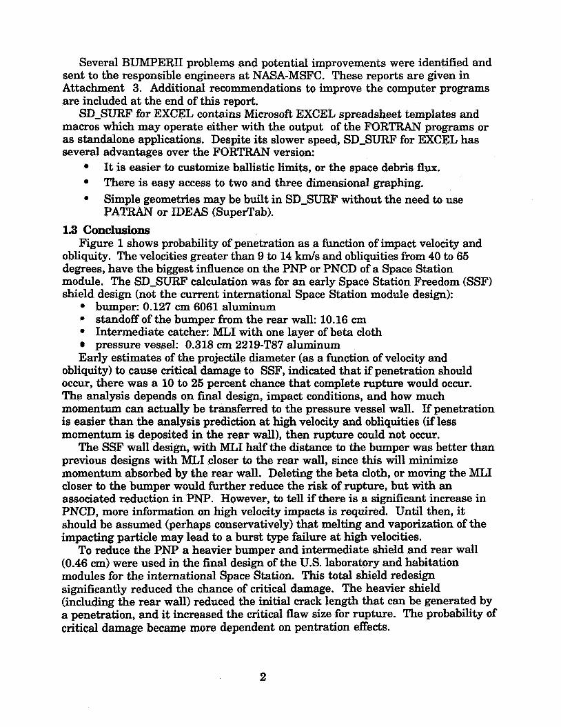
Several BUMPER11 problems and potential improvements were identified and sent to the responsible engineers at NASA-MSFC. These reports are given in Attachment 3. Additional recommendations to improve the computer programs are included at the end of this report.
SD-SURF for EXCEL contains Microsofi EXCEL spreadsheet templates and macros which may operate either with the output of the FORTRAN programs or as standalone applications. Despite its slower speed, SD-SURF for EXCEL has several advantages over the FORTRAN version:
It is easier to customize ballistic limits, or the space debris flux. There is easy access to two and three dimensional graphing. Simple geometries may be built in SD-SURF without the need to use PATRAN or IDEAS (SuperTab).
1.8 Conclusions
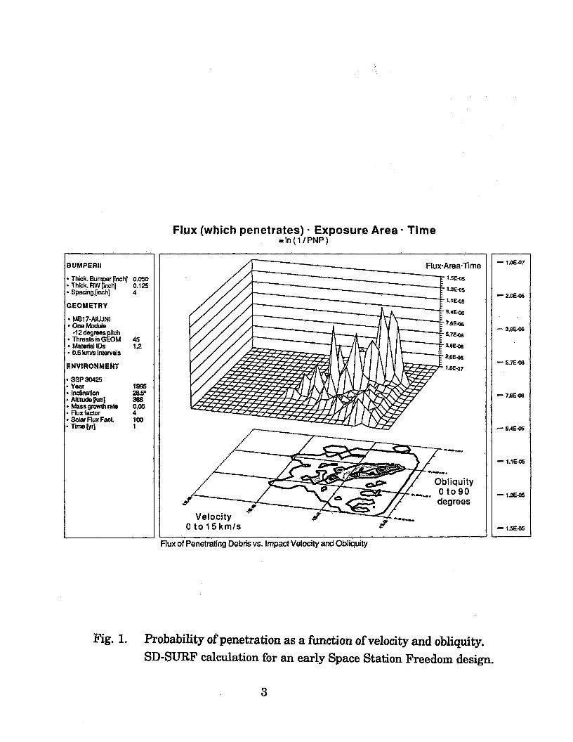
obliquity. The velocities greater than 9 to 14 km/s and obliquities from 40 to 65 degrees, have the biggest influence on the PNP or PNCD of a Space Station module. The SD-SURF calculation was for an early Space Station Freedom (SSF) shield design (not the current international Space Station module design):
Figure 1 shows probability of penetration as a function of impact velocity and
0 bumper: 0.127 cm 6061 aluminum 0 standoff of the bumper fiom the rear wall: 10.16 cm 0 Intermediate catcher: MLI with one layer of beta cloth
pressure vessel: 0.318 ern 2219-T87 aluminum Early estimates of the projectile diameter (as a h c t i o n of velocity and
obliquity) to cause critical damage to SSF, indicated that if penetration should occur, there was a 10 to 25 percent chance that complete rupture would occur. The analysis depends on final design, impact conditions, and how much momentum can actually be transferred to the pressure vessel wall. If penetration is easier than the analysis prediction at high velocity and obliquities (if less momentum is deposited in the rear wall), then rupture could not occur.
The SSF wall design, with MLI half the distance to the bumper was better than previous designs with MLI closer to the rear wall, since this will minimize momentum absorbed by the rear wall. Deleting the beta cloth, or moving the MLI closer to the bumper would further reduce the risk of rupture, but with an associated reduction in PNP. However, to tell if there is a significant increase in PNCD, more information on high velocity impacts is required. Until then, it should be assumed (perhaps conservatively) that melting and vaporization of the impacting particle may lead to a burst type failure at high velocities. To reduce the PNP a heavier bumper and intermediate shield and rear wall
(0.46 cm) were used in the final design of the U.S. laboratory and habitation modules for the international Space Station. This total shield redesign significantly reduced the chance of critical damage. The heavier shield (including the rear wall) reduced the initial crack length that can be generated by a penetration, and it increased the critical flaw size for rupture. The probability of critical damage became more dependent on pentration effects.
The objectives of this task were to model the debris cloud formed by a hypervelocity impact , and to define the ballistic limit surface for fragment penetration. 23 ResulQ
Attachment 4 contains a summary debris cloud radiographic measurements by Mr. Andrew Piekutowski of the University of Dayton Research Institute. This addresses both the largest residual fragment as well as the shape and momentum distribution of the debris cloud. Two papers prepared by Mr. Piekutowski are contained in Attachments 5 and 6. The first, described the largest fragment produced by a hypervelocity impact, was presented at the 1992 ALAA Space Programs and Technologies Conference in Huntsville, Alabama. The second has been submitted for review at the 1992 Hypervelocity Impact Symposium. Further review of the fragment penetration ballistic limit, and additional test data is contained in the Handbook. 2.3 Conclusions
a valuable benchmark for hydrocode analysis, as well as a test derived cloud model for momentum analysis of rear wall deformation.
Three fragment types are of concern. For spherical projectile, either the largest remaining fragment or a general dispersion of uniformly sized fragments can produce penetrations. For cylindrical projectiles, a fragment of spall from the bumper can be the most lethal. This bit of spall comes off normal to the impacting projectile flat, and it is faster than the remainder of the debris cloud.
The penetration resistance of shields with intermediate shields (including MLI with beta cloth) requires empirical determination. Projectile shape can have a significant influence on the ballistic limit. However, the SD-SURF computer code showed that the fragment penetration mechanism has very low influence on the overall PNP for current SSF designs.
The mass and velocity distribution that impacts the rear wall is strongly influenced by the presence of intermediate shields. The effects are modeled analytically, but there is no experimental verification.
The descriptions and analysis of post impact debris cloud radiographs provides
4
TASK 3 - S'IRUC- ANALYSIS s1 O'ltrjeCtiVB
The objective of this task was to analyze structural deformation and fracture by an impulsive load generated by a hypervelocity impact. This includes deformation, crack growth and residual strength assessment. 3.2 Results
test articles that had sufficient Kevlar cloth intermediate shields to prevent fragment penetration. These results are presented in the Handbook for Structural Damage Prediction and Analysis for Hypervelocity Impact (Attachment 7).
due to an initial Gausian momentum intensity distribution (Wilkinson's assumption). He curve fit these and previous STEALTH analysis results to give a dimensionless parameter to predict failure. This work is summarized in the Handbook and included in detail in an Appendix to the Handboo.
Mr. William Roberts performed HULL and NASTRAN analyses at the Michoud Assembly Facility for comparison to the measured deformation. The HULL analyses gave the correct qualitative shape, although more analyses would be required to completely match the correct momentum (with rebound), momentum distribution, and material properties. The NASTRAN 3D sheet elements appeared to accentuate the thinning and deformation at the center of the specimen. This was true for 10.16 and 30.48 cm radius pie slices.
Finite element models of a SSF size cylinder with a longitudinal crack were constructed to determine whether cracks generated by hypervelocity impact could cause catastrophic rupture due to internal pressure. The models gave results consistent with NASA-FLAGRO. Furthermore, equations were developed to allow linear elastic fracture mechanics analysis of a cylinder with cracks emanating from a hole, as well as influence (or weight) functions for arbitrary loads. Other finite element models were developed on CADDS to actually model a cylinder with stiffeners and a hole, but the time required to develop the model geometry and perform the minimum NASTRAN analysis prohibited completion of those analyses.
anticipated, were predicted for an early Space Station Freedom wall design. These are discussed in the Handbook. Since the bumper and MLI plus beta cloth blanket were not optimized for the rear wall thickness, a higher loading rate on the rear wall is not well approximated by the Gausian momentum intensity distribution assumed by Wilkinson. This can lead to necking away from the centerline, or spall in the rear wall. Wide area spall of the rear wall can occur at velocities greater than 6 k d s and has been observed in 0.32 mm 2219 sheet.
Rear wall thickness and permanent displacement was measured on several
Mr. David Grove of UDRI performed EPIC analyses of rear wall deformation
Two different failure mechanisms, spall and necking, that were not originally
5
3.3 conclusions The measurements of rear wall thinning and deformation provide a valuable
benchmark for transient elastic-plastic analysis codes. Thinning of the rear wall did not depend on edge constraints (although overall
displacement was influenced by the edge constraints). The NASTRAN pie shaped sheet element did not produce results consistent
with HULL or EPIC which were 2D axisymetric with 4 to 6 brick elements true the thickness. Some of the problem with the problem with the NASTRAN runs may be that bending was significant for the assumed momentum intensity distribution and rear wall thickness. (This was at the bounds of where Wilkinson noted the beginning of bending effects.)
Three high velocity failure mechanisms are of interest: General deformation, bulging and failure at the centerline as predicted by the Wilkinson's model. Plug or trapdoor type failure with necking and failure at the radius of the debris cloud. Heavier intermediate shields or catchers can slow down the momentum transfer to the rear wall transition to a Wilkinson failure mode. Spall of a large area due to a impulse from the liquid or gaseous debris cloud. Spall failure should extrapolate with projectile energy rather than momentum. (The peak pressure varies linearly with impact velocity for the same momentum.) 'phis is not favorable for PNP predictions, but should be beneficial to PNCB if more of the momentum passes through the wall.
0
The linear elastic fracture mechanics stress intensity influence function for a longitudinal crack in a cylinder was calculated. It is very different than the influence function for a crack in a flat plate. Loads at the center of the crack have a significant bending effect not present in the flat plate.
Crack growth due to impact may be analyzed by an energy balance between the initial kinetic energy of the rear wall, and energy dissipation by deformation and cracking. Estimating the kinetic energy of the rear wall is the most questionable part of the analysis.
thickness = 0.125 inches (0.318 cm)) is calculated to be 23 cm in total length. While the central hole may make the critical crack length longer, due to air pressure on the inward-bent petals, this effect should not be counted on to prevent fracture.
diagonal between two nodes (53.2 an center to center longitudinally along the cylinder). The stiffener spacing would have to be one third the current spacing (53.2 cm center to center) to be of value as a crack stopper.
The critical flaw length that will continue to propagate in SSF (rear wall
The SSF integrally machined stiffeners will not stop a crack which spans the
6
T.IASK4-HYPERVEU)CPI'YTESTS 41 Objectives
clouds and test an advanced shield concept and analyze interior penetration effects. Several specific tests were designed by MSFC and the raw test results were sent to the technical monitor at MSFC for analysis. 4 2 Results
Attachment 8 contains test results that were sent to MSFC for analysis. 4.3 Conclusions
impact debris cloud.
spherical impacting at 4 5 O obliquity at 6.4 W s .
radiographic measurements of fragments in the interior of a module after an impact.
The objective of this task was to perform hyperveloci ts to verify the debris
The debris cloud results were documented and analyzed in Attachment 4.
These tests added to a unique and valuable set of reference data on the post
A textured bumper was not any more effective than a flat sheet in shattering a
The interior penetration effects provided a unique capability for flash
TASK 5 - CONSULTA!DONTO MSF'C 5.1 objectives
The objective of this task was to provide consultation on related issues and problems as requested by NASA-MSFC. 5 2 Resulb
Attachment 9), and the BUMPER11 suggestion and problem reports (included in Attachment 3).
This included telecons, informal analyses and reports (included in
TASK6-HANDBOOK &l objectives
The objective of this task was to prepare a handbook for meteoroid and space debris damage assessment. 6.2 Results
Hypervelocity Impact is included as Attachment 7. The Handbook for Structural Damage Prediction and Analysis for
7
7 RECOMNIENDATONS 7.1 HypervelocityTesting
requirements, but the testing of one and two bumper shields continues to reveal the phenomenology of penetration, which allows the analyst to develop better predictive tools. Launcher development is also progressing with the promise of well characterized (if not well shaped) projectiles in the 10+ W s regime. The following recommendations highlight those areas in special need of development.
Hypervelocity testing is expensive and restricted in velocity compared to design
7.1.1 scaled Velocity Te~titlg Scaled velocity testing has been well developed to characterize the post impact
debris cloud. The use of cadmium on cadmium or lead on lead have provided good benchmarks for hydrocode analysts. Further use of this approach is needed to model rear wall failure in the 10+ k d s regime. In particular, oblique impacts and the influence of intermediate layers (such as the Space Station Freedom thermal blankets) need to be characterized.
While the cloud is in the correct physical state, the physics of rear wall impact also need to be correctly modeled. The possible rear wall failure mechanisms for liquidhapor impingement must be clearly defined and modeled. The rate of application will influence whether spall can occur and the type of momentum failure and tearing. Schmitt et a1 observed that spall occurred for aluminum-on- aluminum impacts but not for cadmium-on-cadmium for the same dimensionless impact speed. However, this is still the most promising technique to qual* analytical models of bulging and tearing that may occur for oblique impacts at 10+ km/s.
7.12 Multiple Bumper Penetration Riesistance Testing Experimental design techniques are needed to improve the multi-shock
technique. Whipple bumper systems have been developed through testing to understand the physical phenomena. However, the number of variables in a multi-shock bumper system precludes this type of approach. The variables include the materials, thickness and spacing of each layer. Two bumper systems have started to address these issues, but four-bumper systems have been restricted to identical evenly spaced bumpers. Experimental design techniques may be able to further optimize the design of multiple bumpers.
But multiple bumpers require greater standoffs spread out momentum. Multiple bumpers are better at breaking up particles than single bumpers.
7.18 Crack Growth An accurate accounting of momentum is needed to develop a general
predictive methodology for crack growth. This should include the use of momentum pendulums for tests at and beyond the threshold of penetration.
about crack growth from small specimens. Boundary conditions should be well characterized before drawing conclusions
8
7.1.4 Round Robin Ligbt Gas Gun Testing Bumper hole size data has indicated that technique differences can influence
the results of light gas gun tests. A small round robin ‘different laboratories should be developed to quantify if there is an influence on rear wall penetration. While differences in the ballistic limit may be within normal scatterband, flattening of the projectile during launch may be a significant contributor to the scatterband.
7.2 ImpactAnalysis
72.2 HydrocoaeAnalysis Hydrocode predictions of rear wall momentum should be recorded both when a
penetration is predicted and when it is not predicted. This is necessary for bulging and cracking analyses at much longer times than used for cratering or hole-out analyses. (Typical durations are 5 to 20 microseconds for penetration by cratering and 50-100 microseconds for bulging, and longer for tearing.)
Large standoff multiple bumper analyses, both monolithic and cloth bumpers, present extreme challenges to hydrocode modelers. However, these analyses are needed for the next generation of bumper systems.
7.2.2 SpallAnalysis Rear wall spall typically needs finer meshes than used currently, but it is
essential to account for this failure mechanism. Parametric studies of debris cloud interaction with the rear wall are needed to develop better models. Again, oblique impact is most significant.
7.2.3 I)eformaton Continued deformation analysis is needed with newly developed post-impact
cloud models and better material properties. The most success has been achieved with Gausian momentum intensity distributions as starting conditions, but a time dependent momentum transfer is more representative of the physics when an intermediate shieldkatcher is present.
Resolve the problem in using sheet elements for rear wall deformation (as available in N A S W and other codes). Examine the sensitivity of HULL and EPIC to the number of brick elements through the thickness. The simpler 3D pie slice model with sheet elements would be desirable for crack petaling studies instead of a 3D model with multiple brick elements through the thickness.
702.4 Et.actureAnaly-sis R-curve analysis of crack growth should be developed to account for plastic
behavior at the crack tip. The state of stress and strain around an impact induced crack is not the same as a fatigue crack. Elastic-plastic crack growth through an integrally machined stiffener is also different than the elastic solutions developed in this handbook.
9
7.3 DesignEI---mm~tiom The use of crack stoppers should be used whenever practical. This includes
add-on stiffeners as well as integrally machined stiffeners. Integrally machined stiffeners may be effective in containing the original impact induced flaw. Add-on crack stoppers could be selectively added to those areas at highest risk for momentum failure. Titanium crack stoppers between waffle nodes could pick up the load from a large petaled hole.
7.4 Env;mnmc?ll~babilityAnsllysig There are several improvements that could be made to either or both
BUMPERII and SD-SURF.
7.4.1 Collision Avoidance For critical damage estimates, the effect of collision avoidance on the effective
debris flux should be included.
7.4.2 BUMPERXI - Make separate rootfiles for Geometry and Response. Use the SuperTab
filename as the root for the GEM file. Read input from a file (besides using Batch.com) (Included in Martin revisions to BUMPERII version 1.2a.)
suggested fixes (to avoid jumping into IF-THEN or DO loops) in the next release of BUMPERII. For Macintosh applications with either larger problems or reduced memory requirements, there should be an option to compile the RESPONSE, GEOMETRY and SHIELD modules separately.
-
- Maintain Macintosh compatibility in future updates. Include the
-
7.4.2.1 BUMPERII - RESPONSE - -
Add the ability to repeat a PID from memory Edit an existing PID. Select it by number and replace with another or recalculate the ballistic limit surface. Open an existing RESPONSE file as new, or append it to the current file for editing. Save a RESPONSE file, edit the data in memory and save as a different RESPONSE file. Add the CONTOUR feature of stepping through shield sizes. This would be useful with the “All” option in PSURF.
-
-
-
7.4.2.2 BUMPERII - GEOMETRY - Add a graphic to the Macintosh version to show the rotation axes.
10
- Include a NASTRAN translator with BUMPERII. (Although the PATRAN translator in version 1.3 reduces the need for this option.)
7.4.2.3 BUMPERII - SHIELD - Add an option to average the diameter to penetrate (and the PNP) over a
range of obliquities to account for granularity in the GEOMETRY model. (This will account for the fact that modules have curved surfaces rather than flat facets modeled in SUPERTAB or PATRAN.) This option should be selectable by either range or PID number so that truly flat surfaces will be modeled correctly. This would require input by the user of the typical angle subtended by the flat facets. Automatically report the breakdown of PNP, exposure area and shield mass among different PIDs that may be selected in one range.
-
7.4.3 SD-SURF - Smooth A-SURF and or PSURF output to remove the effects of using
large facets ( 1 5 O ) and large steps in threat velocity (45 threats in 180 degrees). This will be a more realistic approximation of a curved surface such as a module. It will also aid in the interpretation of the results.
Analyze meteoroids separately, or both meteoroids and debris. Make one large SD-SURF program and automatically pass file information. Add contour and 3d charting to the Macintosh version. -
7.4.3.2 SD-SURF - A-SURF - Create new files with different ranges in the same session (read GEM file
only once), or create multiple tables in one file (must also modify P-SURF). Add the text based contour map used in P-SURF to A-SURF. Generate the area arrays for a sphere automatically without GEOMETRY. (As done in A.R,EA-Maker Macro.) The sphere is useful for a spacecraft that is not Earth oriented. Generate the area arrays as done in the AREAJWXER EXCEL Macro. (This would not do the shadowing performed by BUMPERII. Adaptation of existing graphics packages to GEOMETRY may be more effective.)
- -
-
11
7.4.3.3 SD-SURF - P-SURF - Put subtotals for each obliquity and each velocity (1 km/s increments) on
the graph (and add same feature to PNP-Template). Include shield mass calculations as performed by SHIELD. Write PID descriptions to screen before asking which PID to use. Output only those PID descriptions used in an analysis. Process multiple selectable PIDs instead of just one or all.