Moeller Wiring Manual 02/05 7-1 7 Circuit-breakers Page Overview 7-2 Overview, shunt releases 7-3 Undervoltage releases 7-4 Contact sequence of the auxiliary contacts 7-5 Internal circuit diagrams 7-7 Remote switch-off with voltage releases 7-9 Application of the undervoltage release 7-11 Shutdown of the undervoltage release 7-12 Indication of the switch position 7-13 Short-time delayed circuit-breakers – internal circuit diagrams 7-14 Mesh network circuit-breaker 7-15 Remote operation with motor operator 7-16 as a transformer switch 7-17 with residual-current release 7-18 IZM circuit-breaker 7-22 For Immediate Delivery call KMParts.com at (866) 595-9616
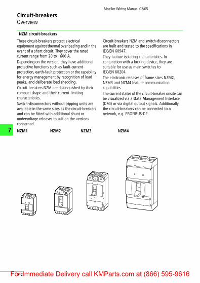
These circuit-breakers protect electrical equipment against thermal overloading and in the event of a short circuit. They cover the rated current range from 20 to 1600 A.Depending on the version, they have additional protective functions such as fault-current protection, earth-fault protection or the capability for energy management by recognition of load peaks, and deliberate load shedding.Circuit-breakers NZM are distinguished by their compact shape and their current-limiting characteristics.Switch-disconnectors without tripping units are available in the same sizes as the circuit-breakers and can be fitted with additional shunt or undervoltage releases to suit on the versions concerned.
Circuit-breakers NZM and switch-disconnectors are built and tested to the specifications in IEC/EN 60947.They feature isolating characteristics. In conjunction with a locking device, they are suitable for use as main switches to IEC/EN 60204.The electronic releases of frame sizes NZM2, NZM3 and NZM4 feature communication capabilities.The current states of the circuit-breaker onsite can be visualized via a Data Management Interface (DMI) or via digital output signals. Additionally, the circuit-breakers can be connected to a network, e.g. PROFIBUS-DP.
NZM1 NZM2 NZM3 NZM4
7-2or Immediate Delivery call KMParts.com at (866) 595-9616
Moeller Wiring Manual 02/05
F
Circuit-breakersOverview, shunt releases
7
IZM circuit-breakers These circuit-breakers protect electrical equipment in the rated current range from 630 to 6300 A. They have digital tripping electronics, which are available in four different versions.The tripping units offer extensive protection and signalling functions, extending from standard short-circuit and overload protection to energy management with data transmission.
Circuit-breakers IZM are built and tested to the specifications in IEC/EN 60947. They feature isolating characteristics. In conjunction with a locking device, they are suitable for use as main switches to IEC/EN 60204.The circuit-breakers in the IZM range are also available as IN switch-disconnectors without tripping units.
Shunt releases A (Q1)
IZM1 IZM2 IZM3
An electromagnet which, when a voltage is applied, actuates a tripping mechanism. When de-energized, the system is in the rest position. A normally open contact actuates the system. If the shunt release is rated for intermittent duty, the intermittent operation must be ensured by positioning appropriate auxiliary contacts (usually HIN/S1) upstream of the circuit-breaker.
Shunt releases are used for remote tripping when an interruption in the voltage is not intended to lead to automatic disconnection. Tripping does not occur in the event of wire breakage, loose contacts or undervoltage.
L1(L+)
-Q1
-S11
C1
C1C2
Q1
E1 -Q1
0
C2
N(L-, L2)
7-3or Immediate Delivery call KMParts.com at (866) 595-9616
Moeller Wiring Manual 02/05
7
F
Circuit-breakersUndervoltage releases
Undervoltage release U (Q1)
Off-delayed undervoltage release UV (Q1)
An electromagnet which actuates a tripping mechanism upon interruption of the voltage. The system is in the rest position when energized. Actuation is produced by a normally closed contact. Undervoltage releases are always designed for uninterrupted operation. These are the ideal tripping elements for totally reliable interlocking tasks (e.g. Emergency-Stop).
Undervoltage releases trip the circuit-breaker when the power fails in order, for example, to prevent motors from restarting automatically. They are also suitable for very reliable interlocking and remote switching off since disconnection always occurs in the event of a fault (e.g. wire breakage in the control circuit). The circuit-breakers cannot be closed when the undervoltage releases are de-energized.
The off-delayed undervoltage release is a combination of a separate delay unit (UVU) and the respective release. This release is used to prevent brief interruptions in power leading to disconnection of the circuit-breaker. The delay time is adjustable between 0.06 and 16 s.
N(L-, L2)
L1(L+)
D1
D2-Q1
-Q1
D1D2
E1
Q1 U<
U<
0-S11
L1(L+)
-S110
N(L-, L2)
-Q1
D2D1
D2
D1U<
Q1
-Q1E1
U<
7-4or Immediate Delivery call KMParts.com at (866) 595-9616
Moeller Wiring Manual 02/05
F
Circuit-breakersContact sequence of the auxiliary contacts
7
Standard auxiliary contact HIN
Trip-indicating auxiliary contact RHI, new designation: trip-indicating auxiliary contact HIA
Used to provide command or signal outputs from processes which are governed by the position of the contacts. They can be used for interlocking with other switches, and for the remote indication of the switching state.
• Standard auxiliary contacts behave like main switch contacts
• Switch position indication• Interlocking• Disconnection of the shunt release
Used to provide command and signal output relating to electrical tripping of the circuit-breaker (trip position +) as is required, for example, for mesh network switches. No pulse is produced when the switch is opened or closed manually, or by a motor operator.
• Indication that the switch is in the tripped position
• Switch position indication only if tripping is caused by, for example, overcurrent, short-circuit, test or voltage release. No fleeting contact when switched on or off manually or switched off with the motor (exception: manual switch off with motor operator NZM2, 3, 4).
0 r I
Switch on
0 R I
Switch off
+ R I
Trip
Q contacts closed
q contacts opened
L1L2L3
HIN
L1L2L3
HIN
L1L2L3
HIN
I
I
+ I
1
1
1
L1L2L3
HIA
L1L2L3
HIA
L1L2L3
HIA
+
1
I
I
1I
7-5or Immediate Delivery call KMParts.com at (866) 595-9616
Circuit-breakersContact sequence of the auxiliary contacts
Moeller Wiring Manual 02/05
7
F
Early-make auxiliary contact HIV
Used to provide command or signal outputs from processes which are initiated before the closure or opening of the main contact system. Because they close early, they can be used for interlocks with other switches. Furthermore, they allow a switch position indication.
The HIV has the same position in the tripped position of the circuit-breaker and the off position of the circuit-breaker. Because of their early-make feature, they can be used for energizing the undervoltage release (a section “Undervoltage releases”, page 7-4).
0 r I
Switched on
0 R I
Switch off
+ R I
Trip
Q contacts closed
q contacts opened
NZM 1, 2, 3
L1L2L3
HIV
I
I
+1
1
1
I
L1L2L3
HIV
L1L2L3
HIV
NZM 4I
I
+1
1
1
I
L1L2L3
HIV
L1L2L3
HIV
L1L2L3
HIV
7-6or Immediate Delivery call KMParts.com at (866) 595-9616
Moeller Wiring Manual 02/05
F
Circuit-breakersInternal circuit diagrams
7
NZM1
NZM2
Contact elements M22-K10 (K01) from the RMQ-Titan range from Moeller are used for the auxiliary contacts. Two early-make auxiliary contacts (2 NO) are also available.Maximum component fitting:
Details about the auxiliary contacts: a section “Maximum component fitting:”, page 7-7
1.11L1 L2 L3
T1 T2 T3
1.13
4.11
3.13
3.23
1.14
4.13
4.14
1.12
4.12
3.14
3.24
HIN
-Q1
HIA HIVI> I> I> NZM
1 2 3 4
HIN, 1 NO or 1 NC 1 2 3 3
HIA, 1 NO or 1 NC 1 1 1 2
HIV, 2 NO 1 1 1 1
L1 L2 L3
T1 T2 T3
1.13
4.11
3.13
3.23
1.14
4.13
4.14
4.12
3.14
3.24
HIN
1.21
1.23
1.24
1.22
-Q1
HIA HIVI> I> I>
1.11
1.12
7-7or Immediate Delivery call KMParts.com at (866) 595-9616
Circuit-breakersInternal circuit diagrams
Moeller Wiring Manual 02/05
7
F
NZM3
NZM4
Details about the auxiliary contacts: a section “Maximum component fitting:”, page 7-7
Details about the auxiliary contacts: a section “Maximum component fitting:”, page 7-7
L1 L2 L3
T1 T2 T3
1.13
4.11
3.13
3.23
1.14
4.13
4.14
4.12
3.14
3.24
HIN
1.31
1.32
1.21
1.22
-Q1
HIA HIVI> I> I>
1.11
1.12
1.33
1.34
1.23
1.24
L1 L2 L3
T1 T2 T3
1.13
4.21
3.13
3.23
1.14
4.13
4.14
4.23
4.24
4.22
4.11
4.12
3.14
3.24
HIN
1.31
1.32
1.21
1.22
-Q1
HIA HIVI> I> I>
1.11
1.12
1.33
1.34
1.23
1.24
7-8or Immediate Delivery call KMParts.com at (866) 595-9616
Moeller Wiring Manual 02/05
F
Circuit-breakersRemote switch-off with voltage releases
7
Remote switch-off with undervoltage releases
Remote switch-off with shunt release
N(L-, L2)
L1(L+)
L1(L+)
N(L-, L2)
-S.
-S.
D1D2
D2-Q1 U<
D1
-Q1
N(L-, L2)
L1(L+)
L1(L+)
N(L-, L2)
-S.
-S.
C1C2
1.131.14 -Q1
C1
-Q1HIN
1.13
1.14
C2
-Q1
7-9or Immediate Delivery call KMParts.com at (866) 595-9616
Circuit-breakersRemote switch-off with voltage releases
Moeller Wiring Manual 02/05
7
F
Main switch application in processing machines with Emergency-Stop function conform to the IEC/EN 60204-1 standard
In the OFF position of the main switch all control elements and control cables which exit the control panel are voltage free. The only live components are the control-voltage tap-offs with the control lines to the early-make auxiliary contact.
-S.
NZM
L1 L2 L3 N
-Q1E1
-Q1 U<
HIV-Q1
D1
D2
L1 L2 L3
HIV-Q1
E1
-Q1 U<
-Q1
NZM
D1
D2
-S.
3.14
3.13
7-10or Immediate Delivery call KMParts.com at (866) 595-9616
Moeller Wiring Manual 02/05
F
Circuit-breakersApplication of the undervoltage release
7
Shut off of the undervoltage release
Starting interlock of the undervoltage release
The early-make auxiliary contact HIV (Q1) can – as shown above – disconnect the undervoltage release from the control voltage when the circuit-breaker is in the Off position. If the undervoltage release is to be disconnected in 2 poles, then a further normally open contact of Q1 must be connected between terminals D2 and N. The early-make auxiliary contact HIV (Q1) will always apply voltage to the undervoltage release in time to permit closure.
Circuit-breakers with undervoltage release produce a positive Off position in conjunction with interlocking auxiliary contacts on the starter (S5), ancillary devices on the motor (e.g. brush lifting, S6) or on all switches in multi-motor drives.The circuit-breaker cannot be closed unless the starter or switch is in the zero or Off position.
L1(L+)
N(L-, L2)
L1(L+)
N(L-, L2)
-Q1
-Q1
HIVD1D2
D1
D2
3.13
3.14
U<3.133.14
-Q1
L1(L+) L1
(L+)
N(L-, L2)
-S5
-Q1 U<
-S6 -Q11.14
D1
D2
1.13
-S6 -S5
N(L-, L2)
D1D2
1.131.14
7-11or Immediate Delivery call KMParts.com at (866) 595-9616
Moeller Wiring Manual 02/05
7
F
Circuit-breakersShutdown of the undervoltage release
Interlocking of several circuit-breakers using an undervoltage release
When interlocking 3 or more circuit-breakers, each circuit-breaker must be interlocked with the series-connected normally closed contacts of the auxiliary contacts on the other circuit-breakers using one contactor relay – for contact duplication – per auxiliary contact. If one of the circuit-breakers is closed, the others cannot be closed.
D1
-Q1
D21.211.22
D1
-Q2
D21.211.22
L1(L+)
N(L-, L2)
-Q2
-Q1D1
D2U<
1.21
1.22-Q1
-Q2D1
D2U<
1.21
1.22
L1(L+)
N(L-, L2)
7-12or Immediate Delivery call KMParts.com at (866) 595-9616
Moeller Wiring Manual 02/05
F
Circuit-breakersIndication of the switch position
7
On and Off indication using standard auxiliary contacts HIN (Q1)
Tripped indication using trip-indicating auxiliary contact HIA (Q1)
P1: OnP2: Off
Trip-indicating auxiliary contacts for mesh network switches
P1: Tripped
L1(L+)
L1(L+)
N(L-, L+)
N(L-, L+)
-F0
1.13
1.14
X1
-P1 -P2X2
X1
X2
-Q1
L1(L+)
-F0
1.11
1.12
X1
-P1 -P2X2
X1
X2
1.141.22
1.21
-F0
1.21X1 X2
X1 X2-P1
-P2
1.131.14
1.22-Q1
N(L-, L2)
N(L-, L+)
L1(L+)
-P1X1
X2
-P1X1
X2
L1(L+)
N(L-, L2)
-F0
-Q1
-F0
4.134.14
4.13
4.14
-Q1
7-13or Immediate Delivery call KMParts.com at (866) 595-9616
Short-time delayed circuit-breakers NZM2(3)(4)/VE enable a time-discriminating network design with variable stagger times. Where the prospective short-circuit currents are extremely high, additional installation protection is achieved by instantaneous releases, which respond without any delay.
NZM2(3)(4)...-VE...Trip block VE Adjustable short-time delay:0, 20, 60, 100, 200, 300, 500, 750, 1000 ms
I>
I>
L1 L2 L3
-Q1
7-14or Immediate Delivery call KMParts.com at (866) 595-9616
Moeller Wiring Manual 02/05
F
Circuit-breakersMesh network circuit-breaker
7
NZM1, NZM2, NZM3, NZM4
Circuit with capacitor unit and shunt release 230 V, 50 Hz.The configuration of the capacitor unit which provides the energy for the shunt release of the
mesh network circuit-breaker can be undertaken independently of the circuit-breaker.Connect the NZM-XCM to the power feed side!
a Mesh network relay
b Mesh network relay with low-capacity contacts
18
19
20
2122
23
24
19
18
20L1
N 21
24
23
22
51 (C1)
a
HIN-NZM...
53 (C2)
230 V50/60 Hz
NZM-XCM
b
19USt24 V H
18
20
21
24
23
22
51 (C1)
HIN-NZM...L1
N
53 (C2)230 V50/60 Hz
NZM-XCM
7-15or Immediate Delivery call KMParts.com at (866) 595-9616
Moeller Wiring Manual 02/05
7
F
Circuit-breakersRemote operation with motor operator
Two-wire control Three-wire control Three-wire control with automatic return to the Off position after tripping
NZM2, 3, 4
L1(L+)
N(L-, L2)
0P1
75
70 71
74
72
NZM-XR
I
L1(L+)
N(L-, L2)
P10
I
75
70 71
74
72
NZM-XR
L1(L+)
N(L-, L2)
P10
75
I
70 71
74
72
NZM-XR
HIA
7-16or Immediate Delivery call KMParts.com at (866) 595-9616
Moeller Wiring Manual 02/05
F
Circuit-breakersas a transformer switch
7
Faults upstream of the low-voltage circuit-breaker, e.g. in the transformer itself, are disconnected by suitable protective devices (e.g. a Buchholz relay) on the high-voltage side. The S7 auxiliary contact of the high-voltage circuit-breaker trips out the NZM transformer switch on the low-voltage side in order to prevent feedback to the high-voltage network. S7 thus isolates the transformer from the network on both
sides. This interlocking with the high-voltage circuit-breaker must always be provided when transformers are being operated in parallel.If only one normally open contact is available as the auxiliary contact, an undervoltage release must be used instead of the shunt release. At the same time, this provides protection against undervoltage.
Circuit-breaker with shunt release Q1 Circuit-breaker with undervoltage release Q1
L1(L+) L1
(L+)
N(L-, L2)
C1C2
Q1
N(L-, L2)
-S7-S7
C1
C2-Q1
L1(L+) L1
(L+)
N(L-, L2)
D1D2
Q1
N(L-, L2)
-S7-S7
D1
D2U<-Q1
7-17or Immediate Delivery call KMParts.com at (866) 595-9616
Moeller Wiring Manual 02/05
7
F
Circuit-breakerswith residual-current release
NZM2-4-XFI, XFI30
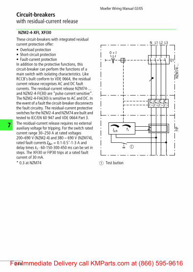
These circuit-breakers with integrated residual current protection offer:• Overload protection• Short-circuit protection• Fault-current protectionIn addition to the protective functions, this circuit-breaker can perform the functions of a main switch with isolating characteristics. Like RCCB's built conform to VDE 0664, the residual current release recognises AC and DC fault currents. The residual-current release NZM74-... and NZM2-4-FI(30) are “pulse current sensitive”. The NZM2-4-FIA(30) is sensitive to AC and DC. In the event of a fault the circuit-breaker disconnects the fault circuitry. The residual-current protective switches for the NZM2-4 and NZM74 are built and tested to IEC/EN 60 947 and VDE 0664 Part 3.The residual-current release requires no external auxiliary voltage for tripping. For the switch rated current range 30–250 A at rated voltages 200–690 V (NZM2-4) and 380 – 690 V (NZM74), rated fault currents IDn = 0.1-0.5*-1-3 A and delay times tV � 60-150-300-450 ms can be set in steps. The XFI30 or FIP30 trips at a rated fault current of 30 mA.* 0.3 at NZM74 a Test button
0 + I
N L1 L2 L3
Q1
NZM
74-..
.FI
P
n tI v
I� I� I� I�
�
7-18or Immediate Delivery call KMParts.com at (866) 595-9616
Circuit-breakerswith residual-current release
Moeller Wiring Manual 02/05
F
7
Residual-current relay PFR with ring-type transformer
The area of application for the relay/transformer combination ranges – depending on the standards involved – from personnel protection to fire prevention to general protection of systems for 1 to 4-pole electrical power networks.There are three different relay types and seven different transformer types available. They cover operating currents ranging from 1 to 1800 A. The three relay types are:• Rated fault current 30 mA, permanently set• Rated fault current 300 mA, permanently set• Rated fault current from 30 mA to 5 A and a
delay time from 20 ms to 5 s which is variable in stages.
The fault current relay indicates when a fault current has exceeded the predefined fault current by using a changeover contact. The contact signal can be processed further as a signal in programmable logic controllers or can initiate a trip via the undervoltage release of a circuit-breaker/switch-disconnector. The compact ring-type transformer is placed without any particular space requirement at a suitable position in the power chain.
230 V AC g 20 % 50/60 Hz3 V A
50/60 Hz 250 V AC 6 A
LOAD
N
NO C NC
L
L1 L2 L3 N
1S2
1S1
5 6 7 8
1 2 3 4
> 3 m – 50 m
7-19or Immediate Delivery call KMParts.com at (866) 595-9616
Circuit-breakerswith residual-current release
Moeller Wiring Manual 02/05
7
F
Trip of circuit-breakers with shunt release and possible external reset of the relay by a pushbutton (NC contact)
5 6 7 8
1 2 3 4
L1
1S1
6 A
1S2
L2 L3N
PFR-W
LOAD
NZM.-XA... C2
C1
-S.
7-20or Immediate Delivery call KMParts.com at (866) 595-9616
Circuit-breakerswith residual-current release
Moeller Wiring Manual 02/05
F
7
Trip of circuit-breakers with undervoltage release and possible external reset of the relay by a pushbutton (NC contact)
5 6 7 8
1 2 3 4
L1
1S1
6 A
1S2
L2 L3N
PFR-W
LOAD
NZM.-XU... D2
D1
-S.
U <
7-21or Immediate Delivery call KMParts.com at (866) 595-9616
7-22
Circuit
7
IZM cir
nment of the control circuit plug
nal
Terminal assig
Internal Terminals Exter
Moeller W
iring Manual 02/05
-breakerscuit-breakers
L/L+UsN/L-
e.g.1)
Jumper with no N-converterL1L2L3N24 V DC externalpower supply
Terminating resistor,if no external system bus module
IZM-XCOM-DP
L/L+ Us
1) Convertor intransformer star pointor summation currentconvertor 1200 A/1 A
DPW
riteFree
FreeClose
Open
OU
TIN
Enable– +
– +– +
66) 595-9616
Control circuit plugs X8, X7, X6, X5 are identical
X8: optional control circuit plug(Connections X8:1 to X8:8 only XFR remote resetwith IZM...-U... and IZM...-D...) G-converter S2
G-converter S1 a Electronic IZM-XW(C) N-converter S2
overload release IZM-XW(C) N-converter S1External voltage transformer star
External voltage transformer L3External voltage transformer L2External voltage transformer L1
0 V DC24 V DC
Internal system bus +Internal system bus –
X7: optional control circuit plugNot available with communication Tripped signalling switch XHIAfunction IZM-XCOM-DP. Signal stateAt the position of Spring-operated stored energyX7 a communications module XEE electrically “ON”is located.
XHIS signalling switch onfirst voltage release
XHIS signalling switch onsecond voltage release
X814
13
12
11
10
9
8
7
6
5
4
3
2
1
X714
13
12
11
10
9
8
7
6
5
4
3
2
1
XA,XU
XE
12
34
56
68
9ExternalInternal
a
For Immediate Delivery call KMParts.com at (8
Circuit-breakersIZM
circuit-breakers
Moeller W
iring Manual 02/05
7-23
L/L+UsN/L-
N/L-USL/L+
Emergency-stopor jumperL/L+
USN/L-
L/L+USN/L-
66) 595-9616
7
X6: standard control circuit plug
XE/A first shunt release
Standard auxiliary switch XHI: S1 “NO”
Standard auxiliary switch XHI: S1 “NC”
Closing release XE/A
“Ready to close” auxiliary switch XHIB
Standard auxiliary switch XHI: S2 “NO”
Standard auxiliary switch XHI: S2 “NC”
X5: optional control circuit plugOnly XUV “non-delayed trip”
XA1, XU, XUV second voltage release
Standard auxiliary contact XHI11/XHI22/XHI31: S3 “NO”, XHI40: S7
Standard auxiliary contact XHI11/XHI22/XHI31: S3 “NC”, XHI40: S7
Standard auxiliary contact XHI22: S4 “NO”, XHI31/XHI40: S8 “NO”
Standard auxiliary contact XHI22: S4 “NC”, XHI31/XH40: S8 “NO”Motor operators
Optional motor cut-off switch XMSa black-white, b brown
X614
13
12
11
10
9
8
7
6
5
4
3
2
1
X514
13
12
11
10
9
8
7
6
5
4
3
2
1
Ma b
For Immediate Delivery call KMParts.com at (8
Circuit-breakersIZM circuit-breakers
Moeller Wiring Manual 02/05
7
F
Cont
rol c
ircu
it is
olat
or
Wir
e no
.
Opt
iona
l aux
iliar
y sw
itch
esSt
anda
rd a
uxili
ary
swit
ches
Term
inal
s
Inte
rnal
Wir
e no
.
Term
inal
s
Leit
ungs
num
mer
XHI1
1(22
)(31)
: S3,
XH
I22:
S4
oder
XH
I40:
S7,
XH
I40:
S8
opti
onal
e Zu
satz
-Hilf
sstr
omsc
halt
erXH
I: S1
, XH
I: S2
Stan
dard
-Hilf
sstr
omsc
halt
er
Klem
men
Inte
rn
Leit
ungs
num
mer
Klem
men
7-24or Immediate Delivery call KMParts.com at (866) 595-9616
Circuit-breakersIZM circuit-breakers
Moeller Wiring Manual 02/05
F
7
Sign
allin
g sw
itch
Term
inal
s
Sign
al 1
st v
olta
ge r
elea
seen
ergi
zed
Sign
al 2
nd v
olta
ge r
elea
seXA
1, X
U o
r XU
V en
ergi
zed
XHIB
XHIF
XHIS
XAXH
IS1
XA1
XU
XUV
XHIA
Wir
e no
.
Term
inal
s
Wir
e no
.
Inte
rnal
color
XHIF
color
XHIB
“Rea
dy t
ocl
ose”
sign
al
“Spr
ing
char
ged”
sign
al
Bell
swit
chal
arm
XHIA
XHIS
XHIS
1
Klem
men
Mel
desc
halt
erer
ster
Spa
nnun
gsau
slös
er X
AM
elde
scha
lter
zwei
ter
Span
nung
saus
löse
rXA
1, X
U o
der
XUV
Leit
ungs
num
mer
Klem
men
Leit
ungs
num
mer
Inte
rn
Eins
chal
t-be
reit
scha
fts-
mel
dung
Spei
cher
-zu
stan
ds-
mel
dung
Aus
gelö
st-
Mel
de-
scha
lter
de-energized
energized
Reset
Trip
de-energized
energized
7-25or Immediate Delivery call KMParts.com at (866) 595-9616
Circuit-breakersIZM circuit-breakers
Moeller Wiring Manual 02/05
7
F
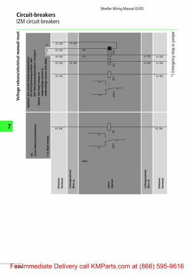
Volt
age
rele
ase/
elec
tric
al m
anua
l res
et
*) E
mer
genc
y-st
op o
r jum
per
1 st
shu
nt r
elea
se
Opt
ion:
2nd
shu
nt r
elea
se o
run
derv
olta
ge r
elea
se o
run
derv
olta
ge r
elea
se w
ith
dela
y
XHIS
XAXH
IS1
XA1
XUXU
V
Wir
e no
.
Term
inal
s
Inte
rnal
color
Term
inal
s
Wir
e no
.
Opt
iona
l: XA
1 zw
eite
r Arb
eits
stro
mau
slös
erXA er
ster
Arb
eits
stro
mau
slös
erXU
Unt
ersp
annu
ngsa
uslö
ser
oder
XUV
Unt
ersp
annu
ngsa
uslö
ser,
verz
öger
t
Leit
ungs
num
mer
Klem
men
Inte
rn
Klem
men
Leit
ungs
num
mer
7-26or Immediate Delivery call KMParts.com at (866) 595-9616
Circuit-breakersIZM circuit-breakers
Moeller Wiring Manual 02/05
F
7
Clos
ing
rele
ase/
elec
tric
al O
N
Term
inal
s
Wir
e no
.
Term
inal
s
Inte
rnal
Elec
tric
al "
ON
"Cl
osin
g re
leas
e
XEE
XE
Wir
e no
.
34
Klem
men
Leit
ungs
num
mer
Klem
men
Inte
rn
XEE
Elek
tris
ch "
EIN
"XE Ei
nsch
altm
agne
t
Leit
ungs
num
mer
7-27or Immediate Delivery call KMParts.com at (866) 595-9616
Circuit-breakersIZM circuit-breakers
Moeller Wiring Manual 02/05
7
F
Mot
or o
pera
tor,
rem
ote
rese
t m
agne
t
colorcolor
Mot
or o
pera
tor
Char
ging
mot
orop
tion
al: m
otor
cut
-off
sw
itch
XM
S
XMS
Wir
e no
.
Term
inal
s
Inte
rnal
Wir
e no
.
Term
inal
s
XFR
rem
ote
rese
t co
ilS
13 c
ut-o
ff s
wit
ch fo
rre
mot
e re
set
coll
XFR
XM Mot
oran
trie
bXM M
otor
antr
ieb
Opt
iona
l: M
otor
abst
ells
chal
ter
XMS
Leit
ungs
num
mer
Klem
men
Inte
rn
Leit
ungs
num
mer
Klem
men
XFR
Fern
-Rüc
kset
zmag
net
S13
Abs
tells
chal
ter
für
Fern
-Rüc
kset
zung
7-28or Immediate Delivery call KMParts.com at (866) 595-9616
Circuit-breakersIZM
circuit-breakers
Moeller W
iring Manual 02/05
7-29
Protective circuits for overcurrent release with breaker status sensor and metering module
er Status Sensor Internal system bus
1)
+-
module
Interner Systembus
-Modul
66) 595-9616
7
Trip magnet forovercurrentrelease
Overcurrentrelease
Internal
Terminals
Inte
rnal
sys
tem
bus
XZM...
BreakMetering module
Metering module
Voltage transformer
BSS
-+
G sensor N sensorN-WandlerG-Wandler
Auslösemagnet fürÜberstromauslösung
ElektronischerÜberstromauslöser
Intern
Klemmen
Inte
rner
Sys
tem
bus
Messmodul
Messmodul
Spannungswandler
BSS
For Immediate Delivery call KMParts.com at (8
Circuit-breakersIZM
circuit-breakers
Moeller W
iring Manual 02/05
7-30
7
Protective circuits for overcurrent release, metering module only
Internal system bus
1)
+-
Interner Systembus
66) 595-9616
Internal
Terminals
Inte
rnal
sys
tem
bus
XZM...
Trip magnet forovercurrentrelease
Overcurrentrelease
Metering module
Metering module
Voltage transformer
-+
G sensor N sensorMessmodul
N-WandlerG-Wandler
Intern
Klemmen
Inte
rner
Sys
tem
bus
Auslösemagnet fürÜberstromauslösung
ElektronischerÜberstromauslöser
Messmodul
Spannungswandler
For Immediate Delivery call KMParts.com at (8
Circuit-breakersIZM
circuit-breakers
Moeller W
iring Manual 02/05
7-31
Protective circuits for overcurrent release, breaker status sensor only
module
Internal system bus
1)
+-
r Status Sensor
Modul
Interner Systembusr Status Sensor
66) 595-9616
7
InternalXZM...
Terminals
Trip magnet forovercurrentrelease
Overcurrentrelease
BSS
Breake
-+
Inte
rnal
sys
tem
bus
G sensor N sensor
Intern
Klemmen
Auslösemagnet fürÜberstromauslösung
ElektronischerÜberstromauslöser
BSS-
Breake
Inte
rner
Sys
tem
bus
N-WandlerG-Wandler
For Immediate Delivery call KMParts.com at (8
NotesMoeller Wiring Manual 02/05
7
F
7-32or Immediate Delivery call KMParts.com at (866) 595-9616