51
36254 Remote I/O ALLEN-BRADLEY ® Remote I/O Interface for IQ plus ® 310A and IQ plus ® 800/810 Indicators Version 2.04 Installation and Programming Manual DISCONTINUED
| Date post: | 11-Jul-2018 |
| Category: |
Documents |
| Upload: | vuongtuyen |
| View: | 218 times |
| Download: | 0 times |

Remote I/OALLEN-BRADLEY® Remote I/O Interface
for IQ plus® 310A and IQ plus® 800/810 Indicators
Version 2.04
Installation and Programming Manual
DISCONTINUED
36254

DISCONTINUED

Copyright © 2000 Rice Lake Weighing Systems. All rights reserved. Printed in the United States of America. Specifications subject to change without notice.
Contents
About This Manual ................................................................................................................................... 11.0 Introduction.................................................................................................................................. 12.0 Installation ................................................................................................................................... 2
2.1 Physical Connections ......................................................................................................................... 22.1.1 Termination Resistance ............................................................................................................................. 32.1.2 Indicator Connections ............................................................................................................................... 32.1.3 A-B Network Connections......................................................................................................................... 3
2.2 DIP Switch Configuration .................................................................................................................... 42.3 LED Indicators .................................................................................................................................... 62.4 Indicator Setup ................................................................................................................................... 6
2.4.1 IQ plus 310A Configuration ....................................................................................................................... 62.4.2 IQ plus 800/810 Configuration................................................................................................................... 7
2.5 Allen-Bradley Serial Stream................................................................................................................. 72.6 Decimal Point Handling....................................................................................................................... 72.7 Installing the 20 mA Current Loop Option ........................................................................................... 8
3.0 Discrete Transfer Commands ...................................................................................................... 93.1 Output Image Table Format ................................................................................................................ 93.2 Input Image Table Format................................................................................................................. 14
4.0 Block Transfer Commands......................................................................................................... 164.1 Set Tare Value .................................................................................................................................. 174.2 Set Setpoint Values .......................................................................................................................... 184.3 Read Setpoint Values ....................................................................................................................... 214.4 Read Accumulator Value .................................................................................................................. 224.5 Read Channel Peak Value ................................................................................................................ 234.6 Read Rate of Change Value.............................................................................................................. 244.7 Read Tare Value ............................................................................................................................... 254.8 Read Gross Value............................................................................................................................. 264.9 Read Net Value ................................................................................................................................ 274.10 Read Multiple Weights .................................................................................................................... 284.11 Set Multiple Setpoint Values............................................................................................................ 304.12 Read Multiple Setpoint Values......................................................................................................... 324.13 Set Batching State .......................................................................................................................... 34
5.0 Operation.................................................................................................................................... 355.1 Test Program for Verifying Remote I/O Interface Operation ............................................................... 355.2 PLC Program for Converting 20-bit Values to Floating Integers......................................................... 375.3 Using Block Transfer to Set and Read Setpoint Values ..................................................................... 385.4 Acquiring a Tare Value...................................................................................................................... 405.5 Reading Weights from Multiple Scale Channels ................................................................................ 41
6.0 Troubleshooting ......................................................................................................................... 427.0 Power Supply Board .................................................................................................................. 44
7.1 Fuse Replacement............................................................................................................................ 447.2 Operating Voltage Conversion .......................................................................................................... 45
8.0 Remote I/O Interface Specifications ......................................................................................... 46Remote I/O Interface Limited Warranty ................................................................................................. 47DISCONTIN
UED
Version 2.04, August 2000

DISCONTINUED
ii Remote I/O Installation and Programming Manual

Introduction
1
About This Manual
This manual provides information needed to installand use the Rice Lake Weighing Systems Remote I/OInterface. The Remote I/O Interface allows IQ plus
®
310A, IQ plus 800, and IQ plus 810 indicators tocommunicate with PLC
®
and SLC
™
controllers usingthe Allen-Bradley
®
Remote I/O network.
1
The Remote I/O Interface is housed in a NEMA 4Xstainless steel enclosure to permit use in washdownenvironments. RS-232 communications is standard; a20 mA current loop interface option is available forconnection to IQ plus 800/810 indicators.
This manual applies to the following softwareversions:
• Remote I/O Interface, Version 2.04• IQ plus 800/810, Version 3.1• IQ plus 310A, Version 5.0
Some procedures described in thismanual require work inside the RemoteI/O enclosure. These procedures are tobe performed by qualified servicepersonnel only.
Authorized distributors and their employeescan view or download this manual from theRice Lake Weighing Systems distributor siteat
www.rlws.com
.
1.0 Introduction
The Remote I/O Interface returns weight and statusinformation streamed from the IQ plus 310A or IQplus 800/810 indicators to the PLC controller. TheRemote I/O Interface provides full control of indicatorfunct ions to the PLC programmer. Indicatorconfiguration and calibration must be done at theindicator front panel.
The following figure shows an example of the RemoteI/O Interface used to connect an IQ plus 810 indicatorto a PLC or SLC controller on an Allen-BradleyRemote I/O network.
The Remote I/O Interface behaves as a node adapterdevice to the master PLC, appearing as a quarter rackof I/O. The PLC controller and Remote I/O Interfacecommunicate using a quarter rack of data slots (4 slotswith 8 bits of input, 8 bits of output per slot).
The PLC controller sends commands to the indicatorthrough the Remote I/O Interface by writing thecommands to the output image table, then readsweight and status data returned through the RemoteI/O Interface in the input image table. These actionsare referred to as discrete reads and discrete writes.See Section 3.0 on page 9 for information about usingdiscrete transfer commands.
Weight Data Formats
Depending on the expected magnitude and requiredprecision of the weight data returned from theindicator, the PLC controller can request weight datain various formats. The discrete write command canspecify weight data be returned to the input imagetable using either 16-bit signed or 20-bit unsignedvalues.
Weight data formats supported by the Remote I/OInterface allow values of –16,777,215 through+16,777,215 to be returned to the PLC controllerusing discrete transfer commands. The maximumdisplayable value for the supported indicators is9,999,999.
1. Allen-Bradley
®
, PLC
®
, and SLC
™
are trademarks of Allen-Bradley Company, Inc., a Rockwell International company.
Warning
ZERO NETGROSS TARE UNITS PRINT
0. ENTER
87 9
54 6
21 3
SCALE#
NEWL.D.
DISPROC
DISPACCUM
DATETIME/
DISP POINTSET
CLEAR
PLC or SLC ControllerRemote I/O Interface
IQ plus 810
Scale Platform
DISCONTINUED

s LEDs cables,ctions.
e. The shown ins to 15
switch
2.0 InstallationThe Remote I/O Interface is designed to be mounted on a wall or other vertical surface, with the four statuon top and the cable connections at the bottom. Before mounting the unit, attach the communicationsselect the termination resistance, and set the configuration DIP switches as described in the following se
2.1 Physical Connections Initial setup and configuration of the Remote I/O Interface requires opening the Interface enclosurenclosure cover uses 16 screws to ensure proper seating of the cover gasket. Use the torquing patternFigure 2-1 to prevent deformation of the gasket when removing and replacing the cover. Torque screwin-lb when replacing the cover.
Figure 2-1. Torquing Pattern for Remote I/O Interface Enclosure
Figure 2-2 shows the layout of the Remote I/O Interface logic board. The following sections describe DIPconfiguration and cable connections to the PLC and indicator.
Figure 2-2. Remote I/O Interface Logic Board Layout
1
2
3
4
5
6
7
8
9
11
13
10
12
1415
16
C11C10
R6
R5
X2
X3
U7C20
D1
U15C6C26C25
C15C14C13C12
U9C
16
1
J4
R11
R17
D2
D3
R12
R14
D4
D5
T1
1 J6
J5
1
R18
R13
C28
C27
U13
C9C8
U14
C23
C4
X1
U10
C18 U16
U17C17
J2
C19 U1
C29
JU1SW1SW2
1 1
RSIP2RSIP1
RSIP3
U12
J1
C24 U11
C7
C5
C3
U6U2
C1
C22 U5
C2U4
R8
R7
R16
R3
R1
U3
J3
C21
R15
R9
23
1
P / N
R10
1
2 10
9
LED CONNECTOR
1
82Ω 150Ω 3
2
4
U8
C30
R4
R2
GND
GND5V T
ES
T
1
11
1
RS
-232
TxD
RS
-232
RxD
RS
-232
GN
D
N/C
20m
A +
IN
20m
A –
IN
20m
A +
OU
T
20m
A –
OU
T
CLE
AR
BLU
E
SH
IELD
CLE
AR
BLU
E
SH
IELD
RE
SE
T
20mA
DISCONTINUED
2 Remote I/O Installation and Programming Manual

vide a
network.istance
th theg the 20
2.1.1 Termination ResistanceIf the Remote I/O Interface is the last, or only, device attached to the PLC, the interface must protermination resistance.
Use Table 2-1 to determine the appropriate termination resistance value and JU1 jumper position for the If the Remote I/O Interface is not the last device in a chain, position the jumper on one pin only. Resvalues for the jumper positions are marked on the Remote I/O Interface logic board.
2.1.2 Indicator ConnectionsConnections to the indicator are made at connector J4on the Remote I/O Interface controller board (seeFigure 2-2 on page 2 for board location of J4).Figure 2-3 shows the J4 connector layout for theRemote I/O Interface. Table 2-2 shows connectionsbetween the Remote I/O Interface and the indicatorsfor RS-232 and 20 mA current loop communications. Figure 2-3. J4 Indicator Connections
NOTE: The 20 mA current loop interface connection requires that the 20 mA option be installed in boRemote I/O Interface and the IQ plus 800/810. See Section 2.7 on page 8 for information about installinmA option.
2.1.3 A-B Network ConnectionsConnections to the Allen-Bradley network are made atconnector J5 on the Remote I/O Interface controllerboard (see Figure 2-2 on page 2 for board location ofJ5). Figure 2-4 shows the connector layout fornetwork connections. Connectors 4–6 are tied toconnectors 1–3 to allow daisy-chaining through theRemote I/O Interface.
Figure 2-4. J5 Network Connections
Network Data Rate Maximum Cable Length Maximum Nodes Termination Resistance JU1 Jumper Position
57.6 Kbps 10 000 ft16 150W 1–2
115.2 Kbps 5000 ft
230.4 Kbps 2500 ft 32 82W 2–3
Table 2-1. JU1 Jumper Positions and Termination Resistance Values
RS
-232
GN
D
No
Con
nect
ion
20m
A +
IN
20m
A –
IN
20m
A +
OU
T
20m
A –
OU
T
J4
6 5 4 3 2 1
RS
-232
TxD
RS
-232
RxD
78
Remote I/O InterfaceJ4 Connections
IQ plus 800/810Connections to J7
IQ plus 310AConnections to J4 Indicator Connections
20 mA –OUT 1 8 N/C –IN 20mA
+OUT 2 7 +IN
–IN 3 10 –OUT
+IN 4 12 +OUT
RS-232 GND 6 12 2 GND RS-232
RxD 7 11 1 TxD
TxD 8 9 3 RxD
Table 2-2. J4 Connections to Indicators for RS-232 and 20 mA Communications
CLE
AR
SH
IELD
BLU
E
CLE
AR
SH
IELD
BLU
EJ5
6 5 4 3 2 1
DISCONTINUED
Installation 3

ication
etngr,
tere.
2.2 DIP Switch ConfigurationTwo banks of DIP switches, SW1 and SW2, are used to configure the Remote I/O Interface for communwith the indicator and the network. Figure 2-5 shows the switch assignments for SW1 and SW2.
Figure 2-5. SW1 and SW2 DIP Switch Assignments
Network Data RateSW2-1 and SW2-2 set the data rate of theAllen-Bradley network. Use Table 2-3 to select thecorrect switch settings for the network.
Last RackSet SW2-3 ON if the Remote I/O Interface linkaddress includes the highest module group in this rackaddress.
Indicator Data RateSW2-4 sets the data rate used to communicate withthe attached indicator. Set this switch OFF for 9600bps, ON for 19.2 Kbps.
Indicator TypeSW2-5 sets whether the attached indicator is an IQplus 800/810 (switch OFF) or an IQ plus 310A(switch ON).
Block TransferSet SW2-6 ON to enable or OFF to disable blocktransfer to the Remote I/O Interface. Setting thisswitch OFF causes the Remote I/O Interface to ignoreunsolicited block transfer requests from the PLC.
NOTE: Switches SW2-7 and SW2-8 should be sOFF. If the Remote I/O Interface returns incrementivalues rather than weights to the PLC controlleverify that SW2-8 is set OFF.
Starting QuarterSwitches SW1-1 and SW1-2 set the starting quar(or group number) used by the Remote I/O InterfacUse Table 2-4 to select the correct switch settings.
1 2 3 4 5 6 7 8
SW2 SW1
StartingQuarter Rack Address
MSBLSB
Net
wor
kD
ata
Rat
e
Indi
cato
r Ty
pe
Last
Rac
k
Indi
cato
r D
ata
Rat
e
Res
erve
d
Link Address
OF
F
OF
F 1 2 3 4 5 6 7 8
Blo
ck T
rans
fer
Remote I/O Data Rate
SW2 Switch Settings
1 2
57.6 Kbps ON ON
115.2 Kbps OFF ON
230.4 KbpsON OFF
OFF OFF
Table 2-3. Network Data Rate
Starting Quarter
Group Number
SW1 Switch Settings
1 2
1st 0 ON ON
2nd 2 OFF ON
3rd 4 ON OFF
4th 6 OFF OFF
Table 2-4. Starting Quarter
DISCONTINUED
4 Remote I/O Installation and Programming Manual

Rack AddressSwitches SW1-3 through SW1-8 are used to set therack address of the Remote I/O Interface. UseTable 2-5 on page 5 to select the correct switchsettings for the rack address. Note that setting a switchOFF acts as a logical “1” and that SW1-3 representsthe least significant bit (LSB) of the rack address.
Rack Address SW1 Switch Settings
Rack Address SW1 Switch Settings
Decimal Octal 3 4 5 6 7 8 Decimal Octal 3 4 5 6 7 8
00 00 ON ON ON ON ON ON 32 40 ON ON ON ON ON OFF
01 01 OFF ON ON ON ON ON 33 41 OFF ON ON ON ON OFF
02 02 ON OFF ON ON ON ON 34 42 ON OFF ON ON ON OFF
03 03 OFF OFF ON ON ON ON 35 43 OFF OFF ON ON ON OFF
04 04 ON ON OFF ON ON ON 36 44 ON ON OFF ON ON OFF
05 05 OFF ON OFF ON ON ON 37 45 OFF ON OFF ON ON OFF
06 06 ON OFF OFF ON ON ON 38 46 ON OFF OFF ON ON OFF
07 07 OFF OFF OFF ON ON ON 39 47 OFF OFF OFF ON ON OFF
08 10 ON ON ON OFF ON ON 40 50 ON ON ON OFF ON OFF
09 11 OFF ON ON OFF ON ON 41 51 OFF ON ON OFF ON OFF
10 12 ON OFF ON OFF ON ON 42 52 ON OFF ON OFF ON OFF
11 13 OFF OFF ON OFF ON ON 43 53 OFF OFF ON OFF ON OFF
12 14 ON ON OFF OFF ON ON 44 54 ON ON OFF OFF ON OFF
13 15 OFF ON OFF OFF ON ON 45 55 OFF ON OFF OFF ON OFF
14 16 ON OFF OFF OFF ON ON 46 56 ON OFF OFF OFF ON OFF
15 17 Reserved 47 57 OFF OFF OFF OFF ON OFF
16 20 ON ON ON ON OFF ON 48 60 ON ON ON ON OFF OFF
17 21 OFF ON ON ON OFF ON 49 61 OFF ON ON ON OFF OFF
18 22 ON OFF ON ON OFF ON 50 62 ON OFF ON ON OFF OFF
19 23 OFF OFF ON ON OFF ON 51 63 OFF OFF ON ON OFF OFF
20 24 ON ON OFF ON OFF ON 52 64 ON ON OFF ON OFF OFF
21 25 OFF ON OFF ON OFF ON 53 65 OFF ON OFF ON OFF OFF
22 26 ON OFF OFF ON OFF ON 54 66 ON OFF OFF ON OFF OFF
23 27 OFF OFF OFF ON OFF ON 55 67 OFF OFF OFF ON OFF OFF
24 30 ON ON ON OFF OFF ON 56 70 ON ON ON OFF OFF OFF
25 31 OFF ON ON OFF OFF ON 57 71 OFF ON ON OFF OFF OFF
26 32 ON OFF ON OFF OFF ON 58 72 ON OFF ON OFF OFF OFF
27 33 OFF OFF ON OFF OFF ON 59 73 OFF OFF ON OFF OFF OFF
28 34 ON ON OFF OFF OFF ON 60 74 ON ON OFF OFF OFF OFF
29 35 OFF ON OFF OFF OFF ON 61 75 OFF ON OFF OFF OFF OFF
30 36 ON OFF OFF OFF OFF ON 62 76 ON OFF OFF OFF OFF OFF
31 37 OFF OFF OFF OFF OFF ON 63 77 OFF OFF OFF OFF OFF OFF
Table 2-5. SW1 Switch Settings for Remote I/O Interface Link AddressDISCONTINUED
Installation 5

erator.
nd IQ 20 mAte I/O
ate with
2.3 LED IndicatorsFour LEDs on the top of the Remote I/O Interface enclosure provide status information for the opTable 2-6 summarizes the function of the LEDs. See Section 6.0 for more troubleshooting information.
2.4 Indicator SetupIndicators communicate with the Remote I/O Interface using the indicator EDP port. Both IQ plus 310A aplus 800/810 indicators support RS-232 communications. The IQ plus 800/810 indicators can also usecurrent loop communications providing the 20 mA option is installed in both the indicator and the RemoInterface.
2.4.1 IQ plus 310A ConfigurationTable 2-7 shows the configuration parameters recommended for the IQ plus 310A indicator to communicthe Remote I/O Interface. See the IQ plus 310A Installation & Service Manual for detailed information aboutconfiguring the indicator.
LED Color Function
Power Green On when external power applied; blinks if microprocessor is not executing
RIO Green On steady when communicating with the PLC
Blinks if node adapter is receiving only RESETcommands from PLC
Check if PLC is in program mode
Off indicates no connection to the network Check that baud rates configured for Remote I/OInterface and PLC match
Check wiring at J5 connector
RxD Red Blinks with every character received from theindicator
May appear to be on steady when indicator isstreaming data
TxD Red Blinks with every character sent to the indicator
Table 2-6. Remote I/O Interface LED indicators
IQ plus 310A Configuration Settings Notes
EDP MODE STREAM Required
BAUD 9600 Must match DIP switch selection on Remote I/O Interface
BITS 8 NONE Required
TERMIN CR
EOL DLY 0 MS
FORMAT REMOTE
CASE UPPER
RESPOND STATUS
PRINTER MODE TICKET Specify TICKET mode to improve indicator performance
SETUP KEYBRD DISABLE Select to disable front panel (blind operation)
TARE RS REGULT Required
TARE FN AUTO
Table 2-7. IQ plus 310A Configuration SettingsDISCONTINUED
6 Remote I/O Installation and Programming Manual

unicate
icator
f 750.1
2.4.2 IQ plus 800/810 ConfigurationTable 2-8 shows the configuration parameters recommended for the IQ plus 800/810 indicators to commwith the Remote I/O Interface. See the IQ plus 800/810 Installation Manual for detailed information aboutconfiguring the indicator.
2.5 Allen-Bradley Serial StreamFigure 2-6 shows the format of the Allen-Bradley serial stream format. This format is output from the indwhen the EDP port AB-RIO and STREAM parameters are set ON.
Figure 2-6. Allen-Bradley Serial Stream (ABSTRM) Format
2.6 Decimal Point HandlingDiscrete TransferDiscrete transfer commands return no decimal point information to the PLC. For example, a value odisplayed on the indicator is returned to the PLC as 7501.
Block TransferBlock transfer commands support decimal point information with no special handling.
IQ plus 800/810 Configuration Settings Notes
CONFIG FEATURE A/B ON A/B FEATURE is enabled at the factory for indicators orderedwith the Remote I/O option. If the A/B FEATURE is OFF, callRLWS for information about activating the feature.
SERIAL EDP BAUD 9600 or 19200 Must match DIP switch selection on Remote I/O Interface
BITS 8 NONE Required
TERMIN CR
EOL DLY 0 MS
ABSTRM EDP
STREAM OFF
Table 2-8. IQ plus 800/810 Configuration Settings
Polarity:<Space> = Positive<–> = Negative
Weight data: 7 digits, right-justified, withdecimal point, leading zero suppression
Termination character:<CR> <LF>
ASCII 0D, 0A (hex)
<TERM><POL> <wwwwwww> <S1> <S2>
Status Byte 1:0100 1xxx Motion0100 x1xx Secondary units0100 xx1x Tare in system0100 xxx1 Net mode
Status Byte 2:0100 1xxx Reserved0100 x1xx Keyed tare0100 xx1x Center of zero0100 xxx1 Overload/underrange
DISCONTINUED
Installation 7

t loopsables
page
2.7 Installing the 20 mA Current Loop OptionThe Remote I/O Interface can communicate with IQ plus 800/810 indicators using the 20 mA curreninterface if the option is installed in both the Interface and the indicator. Installing the 20 mA option diRS-232 communications.
Use the following procedure to install the 20 mA option for the Remote I/O Interface:
1. Disconnect Remote I/O Interface from power source.2. Remove enclosure cover.3. Install 20 mA chip in socket U7 with notch toward inside of circuit board as shown in Figure 2-2 on
2.4. Make cable connections to pins 1–4 on connector J4 (see Section 2.1.2 on page 3).5. Replace enclosure cover and tighten screws using torquing pattern shown in Figure 2-1.6. Reconnect power to Remote I/O Interface.
DISCONTINUED
8 Remote I/O Installation and Programming Manual
mote I/Oo 16-bite input
terfacet imageto a form
the
enan
o
rhefortheitsC
is is
elusite
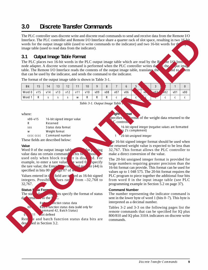
3.0 Discrete Transfer CommandsThe PLC controller uses discrete write and discrete read commands to send and receive data from the ReInterface. The PLC controller and Remote I/O Interface share a quarter rack of slot space, resulting in twwords for the output image table (used to write commands to the indicator) and two 16-bit words for thimage table (used to read data from the indicator).
3.1 Output Image Table FormatThe PLC places two 16-bit words in the PLC output image table which are read by the Remote I/O Innode adapter. A discrete write command is performed when the PLC controller writes data to the outputable. The Remote I/O Interface reads the contents of the output image table, translates the command that can be used by the indicator, and sends the command to the indicator.
The format of the output image table is shown in Table 3-1.
where:v00–v15 16-bit signed integer valueR Reserved sss Status data format w Weight formatcccc cccc Command number
These fields are described below:
ValueWord 0 of the output image table is used for passingvalue data on certain commands. This field should beused only when block transfer is disabled. Forexample, to enter a tare value, use word 0 to specifythe tare value; the Enter Tare command number (44) isspecified in bits 00 through 07 of word 1.
Values entered in this field are treated as 16-bit signedintegers. Possible values range from –32,768 to32,767.
Status Data FormatThe status data format bits specify the format of statusdata returned to the PLC.
000 Remote function status data001 Batch function status data (valid only for
Command 42, Batch Status)010–111 Not defined
Remote and batch function status data bits aredescribed in Section 3.2.
Weight FormatSpecifies the format of the weight data returned to PLC controller:
0 16-bit signed integer (negative values are formatted as 2’s complement)
1 20-bit unsigned integer
The 16-bit signed integer format should be used whthe returned weight value is expected to be less th32,767. This format allows the PLC controller tmake a direct conversion of the value.
The 20-bit unsigned integer format is provided folarge numbers requiring greater precision than t16-bit format can provide. This format can be used values up to 1 048 575. The 20-bit format requires PLC program to piece together the additional four bfrom word 0 in the input image table (see PLprogramming example in Section 5.2 on page 37).
Command NumberThe number representing the indicator commandsent in the lower byte of word 1 (bits 0–7). This byteinterpreted as a decimal number.
Tables 3-2 and 3-3 on the following pages list thremote commands that can be specified for IQ p800/810 and IQ plus 310A indicators on discrete wrcommands.
Bit 15 14 13 12 11 10 9 8 7 6 5 4 3 2 1 0
Word 0 v15 v14 v13 v12 v11 v10 v09 v08 v07 v06 v05 v04 v03 v02 v01 v00
Word 1 R s s s w R R R c c c c c c c c
Table 3-1. Output Image Table Format
DISCONTINUED
Discrete Transfer Commands 9

Decimal Binary Command IQ310A
0 0000 0000 Return Status and Weight N/A
6 0000 0110 Display Gross Weight GN0<cr>
7 0000 0111 Display Net Weight GN1<cr>
9 0000 1001 Front Tare FT<cr>
12 0000 1100 Select LB for Weight Units LB<cr>
13 0000 1101 Select KG for Weight Units KG<cr>
14 0000 1110 Print Request PR<cr>
15 0000 1111 Clear (Reset Indicator) RS<cr>
21 0001 0101 Clear Tare CT<cr>
23 0001 0111 Return Gross XG<cr>
28 0001 1100 Return Net XN<cr>
33 0010 0001 Return Tare XT<cr>
37 0010 0101 Return Currrent Display XD<cr>
43 0010 1011 Zero AZ<cr>
44 0010 1100 Enter Tare AT nnnnnnn<cr>
45 0010 1101 No Operation None
46–127 0010 11100111 1111
Reserved
Table 3-2. IQ plus 310A Remote Commands
DISCONTINUED
10 Remote I/O Installation and Programming Manual

Decimal Binary Command IQ800/810
0 0000 0000 Return Status and Weight N/A
1 0000 0001 Display Channel 0 (Total) K0<cr>KBASE<cr>
2 0000 0010 Display Channel 1 K1<cr>KBASE<cr>
3 0000 0011 Display Channel 2 K2<cr>KBASE<cr>
4 0000 0100 Display Channel 3 K3<cr>KBASE<cr>
5 0000 0101 Display Channel 4 K4<cr>KBASE<cr>
6 0000 0110 Display Gross Weight KGROSS<cr>
7 0000 0111 Display Net Weight KNET<cr>
9 0000 1001 Acquire Tare KTARE<cr>
10 0000 1010 Primary Units KPRIM<cr>
11 0000 1011 Secondary Units KSEC<cr>
14 0000 1110 Print Request KPRINT<cr>
15 0000 1111 Clear KCLR<cr>
16 0001 0000 Clear Accumulator 0 (Total) K0<cr>KDISPACCUM<cr>KCLR<cr>KCLR<cr>
17 0001 0000 Clear Accumulator 1 K1<cr>KDISPACCUM<cr>KCLR<cr>KCLR<cr>
18 0001 0010 Clear Accumulator 2 K2<cr>KDISPACCUM<cr>KCLR<cr>KCLR<cr>
19 0001 0011 Clear Accumulator 3 K3<cr>KDISPACCUM<cr>KCLR<cr>KCLR<cr>
20 0001 0100 Clear Accumulator 4 K4<cr>KDISPACCUM<cr>KCLR<cr>KCLR<cr>
21 0001 0101 Clear Tare KDISPTARE<cr>KCLR<cr>KCLR<cr>
22 0001 0110 Return Gross, Channel 0 (Total) XG#0<cr>
23 0001 0111 Return Gross, Channel 1 XG#1<cr>
24 0001 1000 Return Gross, Channel 2 XG#2<cr>
25 0001 1001 Return Gross, Channel 3 XG#3<cr>
26 0001 1010 Return Gross, Channel 4 XG#4<cr>
27 0001 1011 Return Net, Channel 0 (Total) XN#0<cr>
28 0001 1100 Return Net, Channel 1 XN#1<cr>
29 0001 1101 Return Net, Channel 2 XN#2<cr>
30 0001 1110 Return Net, Channel 3 XN#3<cr>
31 0001 1111 Return Net, Channel 4 XN#4<cr>
32 0010 0000 Return Tare, Channel 0 (Total) XT#0<cr>
33 0010 0001 Return Tare, Channel 1 XT#1<cr>
34 0010 0010 Return Tare, Channel 2 XT#2<cr>
35 0010 0011 Return Tare, Channel 3 XT#3<cr>
36 0010 0100 Return Tare, Channel 4 XT#4<cr>
37 0010 0101 Return Currrent Display P<cr>
38 0010 0110 Batch Start BATSTART<cr>
40 0010 1000 Batch Pause BATPAUSE<cr>
41 0010 1001 Batch Reset BATRESET<cr>
42 0010 1010 Batch Status BATSTATUS<cr>
43 0010 1011 Zero KZERO<cr>
44 0010 1100 Enter Tare Kn<cr>…Kn<cr>KTARE<cr>
Table 3-3. IQ plus 800/810 Remote Commands
DISCONTINUED
Discrete Transfer Commands 11

45 0010 1101 No Operation None
46 0010 1110 Return Accumulator, Channel 0 (Total) XA#0<cr>
47 0010 1111 Return Accumulator, Channel 1 XA#1<cr>
48 0011 0000 Return Accumulator, Channel 2 XA#2<cr>
49 0011 0001 Return Accumulator, Channel 3 XA#3<cr>
50 0011 0010 Return Accumulator, Channel 4 XA#4<cr>
51 0011 0011 Return Rate of Change, Channel 0 (Total) XROC#0<cr>
52 0011 0100 Return Rate of Change, Channel 1 XROC#1<cr>
53 0011 0101 Return Rate of Change, Channel 2 XROC#2<cr>
54 0011 0110 Return Rate of Change, Channel 3 XROC#3<cr>
55 0011 0111 Return Rate of Change, Channel 4 XROC#4<cr>
56 0011 1000 Return Peak, Channel 0 (Total) XPEAK#0<cr>
57 0011 1001 Return Peak, Channel 1 XPEAK#1<cr>
58 0011 1010 Return Peak, Channel 2 XPEAK#2<cr>
59 0011 1011 Return Peak, Channel 3 XPEAK#3<cr>
60 0011 1100 Return Peak, Channel 4 XPEAK#4<cr>
61 0011 1101 Push Displayed Weight to Accumulator, Channel 0 (Total)
K0<cr>KBASE<cr>KPRINT<cr>
62 0011 1110 Push Displayed Weight to Accumulator, Channel 1
K1<cr>KBASE<cr>KPRINT<cr>
63 0011 1111 Push Displayed Weight to Accumulator,Channel 2
K2<cr>KBASE<cr>KPRINT<cr>
64 0100 0000 Push Displayed Weight to Accumulator, Channel 3
K3<cr>KBASE<cr>KPRINT<cr>
65 0100 0001 Push Displayed Weight to Accumulator,Channel 4
K4<cr>KBASE<cr>KPRINT<cr>
66 0100 0010 Lock indicator front panel LOCKON<cr>
67 0100 0011 Unlock indicator front panel LOCKOFF<cr>
68 0100 0100 Set digital output nn on DON#nn<cr>
69 0100 0101 Set digital output nn off DOFF#nn<cr>
70–127 0100 01100111 1111
Reserved
Notes: Commands referring to channels 2–4 are valid only for scales with multi-channel capability. For single-channelscales, commands referring to channel 0 return the same information as channel 1.
Commands shown with shading in the command number column (6–21, 43–44, 61–65) do not update weight datain the PLC. Use commands 0 and 22–37 to return weight data to the PLC.
Data written to the input image table by commands 14, 38, 41, and 61–65 is not changed by repeating thecommand. Successive execution of any of these commands with no other command between executions (forexample, command 61 followed by another command 61) has no effect.
Rate of Change and Channel Peak commands are valid only if these options are installed.
Decimal Binary Command IQ800/810
Table 3-3. IQ plus 800/810 Remote Commands (Continued)DISCONTINUED
12 Remote I/O Installation and Programming Manual

tting theose bits
weighteserved;
end the
write
Using the Output Image TableThe output image table can be thought of as storage for two integers, with each integer one word long. Sebit pattern required for a discrete write command can be accomplished by adding the decimal values of ththat are set to 1, then placing the binary sum in the output image table.
Table 3-4 shows the format of word 1 of the output image table, which includes the command number,format, and status data format specifications. Note that the values of bits 13–15 are always 0: bit 15 is rno status data formats are defined for values using bits 13 and 14.
Table 3-5 shows an example of word 1 of the output image table. In the example, bits are set to sfollowing information on the discrete write command:
• Display Gross Weight command (bits 0–7 = 00000110, 6 decimal)• 20-bit weight format (bit 11 = 1)• Remote function status data format (bits 12–14 = 000)
The integer value of the bits set in the example above are the sum of:Command number (6) + Weight format (2048) + Status Data Format (0) = 2054
Use Table 3-6 to determine the decimal value of word 1 of the output image table for any discretecommand.
Bit 15 14 13 12 11 10 9 8 7 6 5 4 3 2 1 0
Decimal Value of 1 N/A N/A N/A 4096 2048 1024 512 256 128 64 32 16 8 4 2 1
Bit Definition R Status Data Format Wt Reserved Command
Table 3-4. Output Image Table Format (Word 1), Showing Decimal Values for Bits Set to 1
Bit 15 14 13 12 11 10 9 8 7 6 5 4 3 2 1 0
Decimal Value of 1 0 0 0 0 2048 0 0 0 0 0 0 0 0 4 2 0
Bit Definition R Status Data Formt Wt Reserved Command
Table 3-5. Example of Output Image Table Format (Word 1)
Command + Weight Format + Status Data Format = Total Value inOutput Image Table
Number 16-bit 0 Remote Function 0
20-bit 2048 Batch Function 4096
Table 3-6. Chart for Finding Decimal Value of Output Image Table (Word 1)
DISCONTINUED
Discrete Transfer Commands 13

e PLCation torete read
fords
dsl 0) is the
nd
3.2 Input Image Table FormatThe Remote I/O Interface places two 16-bit words in the PLC input image table which are read by thcontroller. The Remote I/O Interface receives data from the indicator, then writes data and status informthe input image table based on parameters specified on the previous discrete write command. A disccommand is performed when the PLC controller reads the data from the input image table.
The format of the input image table is shown in Table 3-7:
where:v00–v15 16-bit signed integer value (v15 is the sign bit)v16–v19 4 high-order bits of 20-bit unsigned integerp Polarity bit for 20-bit integer (0 = positive; 1 = negative). Not valid for 16-bit integers.s00–s10 Status data
ValueWord 0 of the input image table is used to returnweight data to the PLC controller. For values returnedin 16-bit format, bit v15 serves as the sign bit. Valuesreturned in 20-bit format use word 0 and bits v16–v19of word 1, with a polarity bit (word 1, bit 4) to indicatethe sign.
PolarityThe polarity bit is used to indicate the sign of valuesreturned in 20-bit format. This bit is not used for16-bit values.
Status DataStatus data returned on a discrete read command canbe either remote function status data or batch functionstatus data, depending on the format specified on thewrite command.
Status bits should be routinely checkedto ensure that incoming weight data isvalid and that communication with theindicator is active.
For example, if communication with the indicator islost, the weight OK/weight invalid bit (status bit s12)is set. Failure to monitor this bit can cause overflowsor accidents if conditional filling operations are basedon old data.
Tables 3-8 and 3-9 on page 15 show the format ofstatus bits used for remote and batch function statusdata.
About the Channel BitWord 1, bit 7 (status bit 02) serves as a channel bit multichannel indicators using the discrete commanlisted below:
Display Channel (Commands 1–5)Return Gross (Commands 22–26)Return Net (Commands 27–31)Return Tare (Commands 32–36)
The channel bit is set to 0 if one of the commanlisted above is used to make Channel 1 (or Channethe active channel. If one of the listed commandsused to make Channel 2, 3, or 4 the active channel,channel bit is set to 1.
The channel bit is included in both the remote abatch function status data formats.
Bit 15 14 13 12 11 10 9 8 7 6 5 4 3 2 1 0
Word 0 v15 v14 v13 v12 v11 v10 v09 v08 v07 v06 v05 v04 v03 v02 v01 v00
Word 1 s10 s09 s08 s07 s06 s05 s04 s03 s02 s01 s00 p v19 v18 v17 v16
Table 3-7. Input Image Table Format
! Caution
DISCONTINUED
14 Remote I/O Installation and Programming Manual

Word 1 Bit
Status Bit
Remote Function Status Data
Value=0 Value=1
05 s00 Reserved
06 s01
07 s02 Channel = 0 or 1 Channel = 2, 3 or 4
08 s03 Gross Net
09 s04 No tare Tare acquired
10 s05 Primary (LB) Secondary (KG)
11 s06 Standstill In motion
12 s07 Weight OK Weight invalid / Over-range
13 s08 Not zero Center of zero
14 s09 Tare not entered Tare entered
15 s10 Reserved
Table 3-8. Remote Function Status Data Format
Word 1 Bit
Status Bit
Batch Function Status Data
Value=0 Value=1
05 s00 Reserved
06 s01
07 s02 Channel = 0 or 1 Channel = 2, 3, or 4
08 s03 Alarm OFF Alarm ON
09 s04 Batch stopped
10 s05 Batch running
11 s06 Batch paused
12 s07 Digital Input 1 OFF Digital Input 1 ON
13 s08 Digital Input 2 OFF Digital Input 2 ON
14 s09 Digital Input 3 OFF Digital Input 3 ON
15 s10 Reserved
Table 3-9. Batch Function Status Data Format
DISCONTINUED
Discrete Transfer Commands 15

310Aicator,tors with IQ plus
ollowed
numberk Read
mber ofmmandusing 2’s
ows the 5.3 on
4.0 Block Transfer CommandsThe Remote I/O Interface supports block transfer commands for the IQ plus 800/810 and IQ plusindicators. These commands allow the PLC controller to exchange larger blocks of data with the indincluding gross, net, tare, and accumulator values, channel peak and rate of change values (for indicathese options installed), and partial setpoint configuration. Some commands are not supported for the310A indicator.
Supported CommandsTable 4-1 shows the block write and block read commands supported by the Remote I/O Interface.
Using Block Transfer CommandsWhen using block transfer commands, each action is accomplished by sending a block write command fby a block read command.
For example, to set a tare value, a Block Write Command 1 (Set Tare Value) consisting of the command(1), indicator channel number, and the tare value itself is sent to the Remote I/O Interface. Next, a BlocCommand 1 is issued by the PLC controller. The two words of data returned to the PLC contain the nuthe previous block write command (1) and a response code indicating whether or not the block write cowas successful. If the command failed, the command number returned in the block read is set negative (complement).
The following sections provide detailed descriptions of the block transfer commands. Each section shformat used by the block write command, followed by that of the block read command. See Sectionpage 38 for an example of using block transfer to set and read setpoint values.
Command Number Command Name
Block Write Command
Length*
Block Read Command
Length* Valid for
IQ plus 310A
1 Set Tare Value 4 2 Yes
2 Set Setpoint Values 11 2 —
3 Read Setpoint Values 2 11 —
4 Read Accumulator Value 2 4 —
5 Read Channel Peak Value 2 4 —
6 Read Rate of Change Value 2 4 —
7 Read Tare Value 2 4 Yes
8 Read Gross Value 2 4 Yes
9 Read Net Value 2 4 Yes
10 Read Multiple Weights 3 23 —
11 Set Multiple Setpoint Values 4 – 42** 2 —
12 Read Multiple Setpoint Values 2 4 – 42** —
13 Set Batching State 2 2 —
* Command lengths expressed as number of words
** Length of command depends on number of setpoints specified
Table 4-1. Supported Block Transfer Commands
DISCONTINUED
16 Remote I/O Installation and Programming Manual

e format
nel 1 for
ust be
he PLC
et Tare
shows
4.1 Set Tare ValueThe Set Tare Value block write command is used to write a tare value to the indicator. Table 4-2 shows thof the command:
Command NumberSpecifies the Set Tare Value command number, 1.
Channel NumberSpecifies the channel number for the tare value being set. Valid values are 0 through 4. Specify chansingle-channel indicators.
Tare ValueSpecifies the tare value being set.
NOTE: For IQ plus 310A indicators only, tare values must be sent as integers. The tare value mmanipulated to include digits for any decimal positions configured for the indicator.
For example, to send a tare value of 12.5 to an IQ plus 310A configured for two decimal places (0.00), tcontroller must format the tare value as 1250. This value is interpreted by the indicator as 12.50.
Block read command 1 returns a response code to the PLC controller, indicating whether or not the SValue block write command was successful. Possible values for the response code field are:
0 00 Command successful1 01 Command failed2 10 Block write command format not valid
If the block write command failed, the command number returned in word 0 is set negative (-1). Table 4-3the format of the block read command.
Word
Bit Number
Word Contents15 14 13 12 11 10 9 8 7 6 5 4 3 2 1 0
0 0 0 0 0 0 0 0 0 0 0 0 0 0 0 0 1 Command Number (1)
1 0 0 0 0 0 0 0 0 0 0 0 0 0 c2 c1 c0 Channel Number (0–4)
2 v31Tare Value
v16 Tare Value (MSW)
3 v15 v00 Tare Value (LSW)
Table 4-2. Block Write Command 1: Set Tare Value
Word
Bit Number
Word Contents15 14 13 12 11 10 9 8 7 6 5 4 3 2 1 0
0 0 0 0 0 0 0 0 0 0 0 0 0 0 0 0 1 Command Number (1)
1 0 0 0 0 0 0 0 0 0 0 0 0 0 0 r1 r0 Response Code (0–2)
Table 4-3. Block Read Command 1: Set Tare Value (Read Response Code)
DISCONTINUED
Block Transfer Commands 17

ble 4-4
t can be
4.2 Set Setpoint ValuesThe Set Setpoint Values block write command is used to write setpoint information to the indicator. Tashows the format of the command:
Table 4-4. Block Write Command 2: Set Setpoint Values
Command NumberSpecifies the Set Setpoint Values command number, 2.
Setpoint NumberSpecifies the setpoint number being configured. Valid values are 1 through 20, decimal.
Setpoint KindSpecifies the kind of setpoint being configured. Table 4-5 on page 19 shows the kinds of setpoints thaspecified on this parameter:
Word
Bit Number
Word Contents15 14 13 12 11 10 9 8 7 6 5 4 3 2 1 0
0 0 0 0 0 0 0 0 0 0 0 0 0 0 0 1 0 Command Number (2)
1 0 0 0 0 0 0 0 0 0 0 0 n4 n3 n2 n1 n0 Setpoint Number (1–20)
2 0 0 0 0 0 0 0 0 0 0 0 k4 k3 k2 k1 k0 Setpoint Kind (0–18)
3 v31Setpoint Value
v16 Setpoint Value (MSW)
4 v15 v00 Setpoint Value (LSW)
5 b31Band Value
b16 Band Value (MSW)
6 b15 b00 Band Value (LSW)
7 h31Hysteresis Value
h16 Hysteresis Value (MSW)
8 h15 h00 Hysteresis Value (LSW)
9 p31Preact Value
p16 Preact Value (MSW)
10 p15 p00 Preact Value (LSW)
DISCONTINUED
18 Remote I/O Installation and Programming Manual

Value Kind Description
0 OFF Setpoint turned off/ignored.
1 GROSSSP Gross setpoint. Trips when the current gross weight matches this value.
2 NETSP Net setpoint. Trips when the current net weight matches this value.
3 +RELSP Positive relative setpoint. Trips at a specific value above the referenced setpoint.
4 –RELSP Negative relative setpoint. Trips at a specific value below the referenced setpoint.
5 %RELSP Percentile relative setpoint. Trips at a specific percentage value of the referenced setpoint.
6 PAUSE Pauses the batch sequence indefinitely. Operator must activate the START digital input to continueprocessing.
7 DELAY Delays the batch sequence for a specified time. The length of the delay (in tenths of a second) isspecified on the Value parameter.
8 WAITSS Wait for standstill. Pauses the batch sequence until the scale is at standstill.
9 COUNTER Specifies the number of consecutive batch sequences to perform.
10 AUTOJOG Automatically jogs the previous filling operation.
11 COZ Center of zero. The digital output associated with this setpoint is activated when the scale is at center ofzero. No value is required for this setpoint.
12 INMOTON In motion. The digital output associated with this setpoint is activated when the scale is not at standstill.No value is required for this setpoint.
13 INRANGE In range. The digital output associated with this setpoint is activated when the scale is within capacityrange. No value is required for this setpoint.
14 –GROSS Negative gross weight. The digital output associated with this setpoint is activated when the grossweight reading is less than zero. No value is required for this setpoint.
15 –NET Negative net weight. The digital output associated with this setpoint is activated when the net weightreading is less than zero. No value is required for this setpoint.
16 BATCHPR Batch processing signal. The digital output associated with this setpoint is activated whenever a batchsequence is in progress. No value is required for this setpoint.
17 TIMER Tracks the progress of a batch sequence based on a timer.
The timer value, specified in tenths of a second on the Value parameter, determines the length of timeallowed between start and end setpoints. The indicator Start and End parameters are used to specify thestart and end setpoints. If the End setpoint is not reached before the timer expires, the digital outputassociated with this setpoint is activated.
18 CONCUR Allows a digital output to remain active over a specified portion of the batch sequence. Two types ofConcur setpoints can be configured:
Type 1: The digital output associated with this setpoint becomes active when the Start setpoint becomesthe current batch step and remains active until the End setpoint becomes the current batch step.
Type 2: The digital output associated with this setpoint becomes active when the Start setpoint becomesthe current batch step and remains active until a timer expires.
The indicator Start and End parameters are used to specify start and end setpoints. The timer value isspecified in tenths of a second on the Value parameter.
Table 4-5. Setpoint Kind Values DISCONTINUED
Block Transfer Commands 19

columns
value.
(in tenths
dwidth
t will trip
EACT is
Table 4-6 lists the values that can be specified for the Setpoint Kind parameter. Shaded areas in the rightindicate that the setpoint type can be used as a continuous or batch step setpoint.
• Continuous setpoints are free-running, becoming active based on a specified condition or weight • Batch setpoints run sequentially, one at a time, for control of batch processing operations.
Setpoint ValueSpecifies the value used as input for several setpoint types. Values specified can represent weight, time of a second), or the number of repetitions used by counter setpoints.
Band ValueSpecifies the bandwidth value used when the TRIP parameter is set to INBAND or OUTBAND. The banvalue is set to fall equally on either side of the setpoint value.
HysteresisSpecifies a band on either side of the setpoint value that must be exceeded before a continuous setpoinon again once it has shut off.
Preact ValueSpecifies the amount of adjustment used by the PREACT parameter. This parameter is used only if PRset to ON or LEARN.
See the IQ plus 800/810 Installation Manual for detailed information about setpoint configuration.
Decimal Value
Bit Number KindContinuous or
Batch Step
k4 k3 k2 k1 k0 Cont Batch
0 0 0 0 0 0 OFF
1 0 0 0 0 1 GROSSSP
2 0 0 0 1 0 NETSP
3 0 0 0 1 1 +RELSP
4 0 0 1 0 0 –RELSP
5 0 0 1 0 1 %RELSP
6 0 0 1 1 0 PAUSE
7 0 0 1 1 1 DELAY
8 0 1 0 0 0 WAITSS
9 0 1 0 0 1 COUNTER
10 0 1 0 1 0 AUTOJOG
11 0 1 0 1 1 COZ
12 0 1 1 0 0 INMOTON
13 0 1 1 0 1 INRANGE
14 0 1 1 1 0 –GROSS
15 0 1 1 1 1 –NET
16 1 0 0 0 0 BATCHPR
17 1 0 0 0 1 TIMER
18 1 0 0 1 0 CONCUR
Table 4-6. Setpoint Kind Values
DISCONTINUED
20 Remote I/O Installation and Programming Manual

Setpoint
shows
ble 4-8
writeat of the
Block read command 2 returns a response code to the PLC controller, indicating whether or not the Set Values block write command was successful. Possible values for the response code field are:
0 00 Command successful1 01 Command failed2 10 Block write command format not valid
If the block write command failed, the command number returned in word 0 is set negative (-2). Table 4-7the format of the block read command.
4.3 Read Setpoint ValuesThe Read Setpoint Values block write command is used to read setpoint values from the indicator. Tashows the format of the command:
Command NumberSpecifies the Read Setpoint Values command number, 3.
Setpoint NumberSpecifies the number of the setpoint being read. Valid values are 1 through 20.
Block read command 3 returns an 11-word block of setpoint values to the PLC controller. If the blockcommand failed, the command number returned in word 0 is set negative (-3). Table 4-9 shows the formblock read command.
Table 4-9. Block Read Command 3: Read Setpoint Values
Word
Bit Number
Word Contents15 14 13 12 11 10 9 8 7 6 5 4 3 2 1 0
0 0 0 0 0 0 0 0 0 0 0 0 0 0 0 1 0 Command Number (2)
1 0 0 0 0 0 0 0 0 0 0 0 0 0 0 r1 r0 Response Code (0–2)
Table 4-7. Block Read Command 2: Set Setpoint Values (Read Response Code)
Word
Bit Number
Word Contents15 14 13 12 11 10 9 8 7 6 5 4 3 2 1 0
0 0 0 0 0 0 0 0 0 0 0 0 0 0 0 1 1 Command Number (3)
1 0 0 0 0 0 0 0 0 0 0 0 n4 n3 n2 n1 n0 Setpoint Number (1–20)
Table 4-8. Block Write Command 3: Read Setpoint Values
Word
Bit Number
Word Contents15 14 13 12 11 10 9 8 7 6 5 4 3 2 1 0
0 0 0 0 0 0 0 0 0 0 0 0 0 0 0 1 1 Command Number (3)
1 0 0 0 0 0 0 0 0 0 0 0 n4 n3 n2 n1 n0 Setpoint Number (1–20)
2 0 0 0 0 0 0 0 0 0 0 0 k4 k3 k2 k1 k0 Setpoint Kind (0–18)
3 v31Setpoint Value
v16 Setpoint Value (MSW)
4 v15 v00 Setpoint Value (LSW)
5 b31Band Value
b16 Band Value (MSW)
6 b15 b00 Band Value (LSW)
7 h31Hysteresis Value
h16 Hysteresis Value (MSW)
8 h15 h00 Hysteresis Value (LSW)
9 p31Preact Value
p16 Preact Value (MSW)
10 p15 p00 Preact Value (LSW)
DISCONTINUED
Block Transfer Commands 21
icator.
l 1 for
mande block
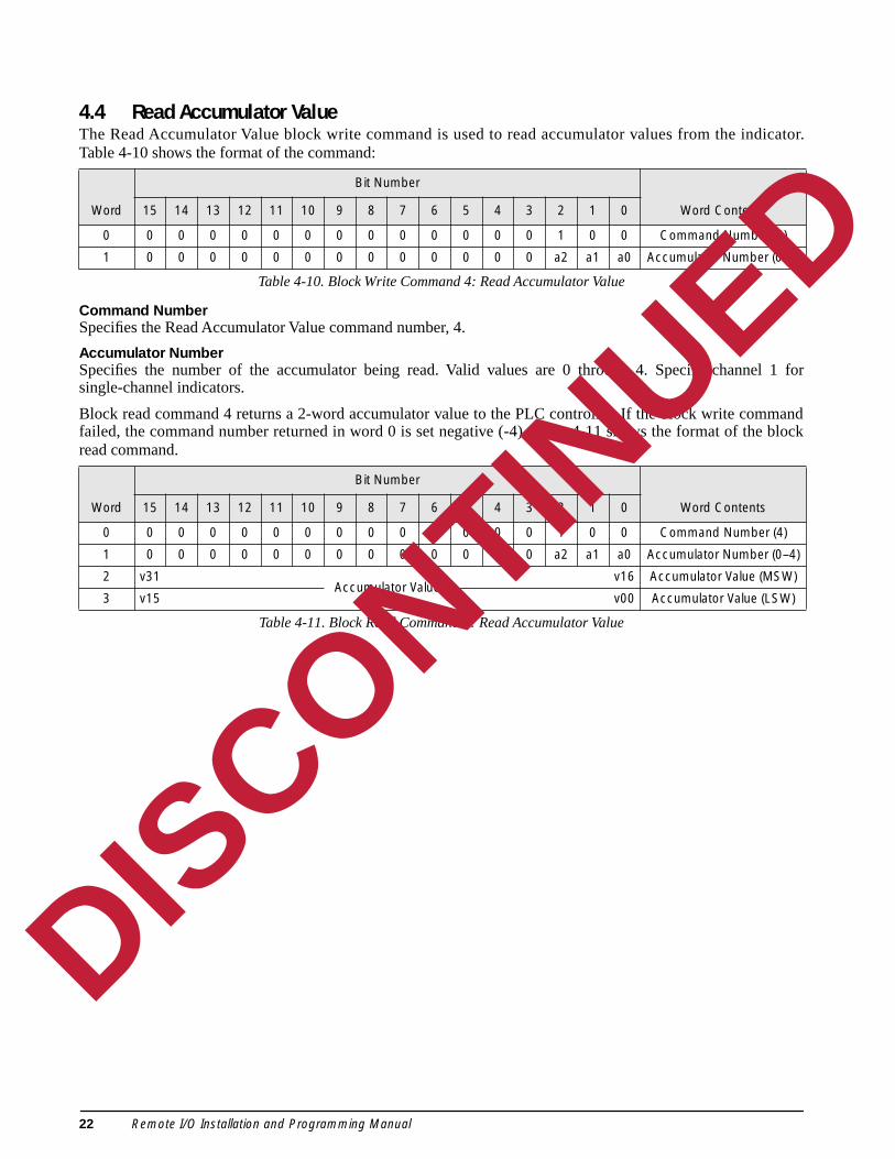
4.4 Read Accumulator ValueThe Read Accumulator Value block write command is used to read accumulator values from the indTable 4-10 shows the format of the command:
Table 4-10. Block Write Command 4: Read Accumulator Value
Command NumberSpecifies the Read Accumulator Value command number, 4.
Accumulator NumberSpecifies the number of the accumulator being read. Valid values are 0 through 4. Specify channesingle-channel indicators.
Block read command 4 returns a 2-word accumulator value to the PLC controller. If the block write comfailed, the command number returned in word 0 is set negative (-4). Table 4-11 shows the format of thread command.
Table 4-11. Block Read Command 4: Read Accumulator Value
Word
Bit Number
Word Contents15 14 13 12 11 10 9 8 7 6 5 4 3 2 1 0
0 0 0 0 0 0 0 0 0 0 0 0 0 0 1 0 0 Command Number (4)
1 0 0 0 0 0 0 0 0 0 0 0 0 0 a2 a1 a0 Accumulator Number (0–4)
Word
Bit Number
Word Contents15 14 13 12 11 10 9 8 7 6 5 4 3 2 1 0
0 0 0 0 0 0 0 0 0 0 0 0 0 0 1 0 0 Command Number (4)
1 0 0 0 0 0 0 0 0 0 0 0 0 0 a2 a1 a0 Accumulator Number (0–4)
2 v31Accumulator Value
v16 Accumulator Value (MSW)
3 v15 v00 Accumulator Value (LSW)
DISCONTINUED
22 Remote I/O Installation and Programming Manual
tor. Thist of the
Specify
ed, thek read
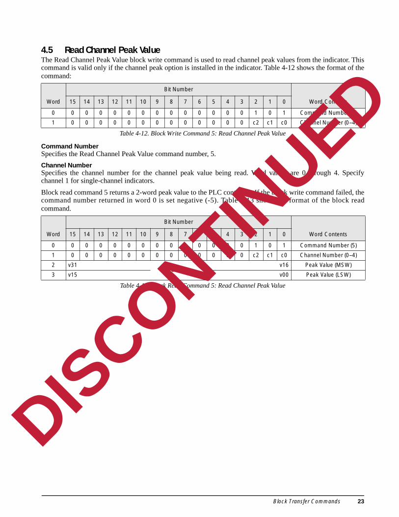
4.5 Read Channel Peak ValueThe Read Channel Peak Value block write command is used to read channel peak values from the indicacommand is valid only if the channel peak option is installed in the indicator. Table 4-12 shows the formacommand:
Table 4-12. Block Write Command 5: Read Channel Peak Value
Command NumberSpecifies the Read Channel Peak Value command number, 5.
Channel NumberSpecifies the channel number for the channel peak value being read. Valid values are 0 through 4.channel 1 for single-channel indicators.
Block read command 5 returns a 2-word peak value to the PLC controller. If the block write command failcommand number returned in word 0 is set negative (-5). Table 4-13 shows the format of the bloccommand.
Table 4-13. Block Read Command 5: Read Channel Peak Value
Word
Bit Number
Word Contents15 14 13 12 11 10 9 8 7 6 5 4 3 2 1 0
0 0 0 0 0 0 0 0 0 0 0 0 0 0 1 0 1 Command Number (5)
1 0 0 0 0 0 0 0 0 0 0 0 0 0 c2 c1 c0 Channel Number (0–4)
Word
Bit Number
Word Contents15 14 13 12 11 10 9 8 7 6 5 4 3 2 1 0
0 0 0 0 0 0 0 0 0 0 0 0 0 0 1 0 1 Command Number (5)
1 0 0 0 0 0 0 0 0 0 0 0 0 0 c2 c1 c0 Channel Number (0–4)
2 v31Peak Value
v16 Peak Value (MSW)
3 v15 v00 Peak Value (LSW)
DISCONTINUED
Block Transfer Commands 23
ndicator. format
hannel 1
mande block
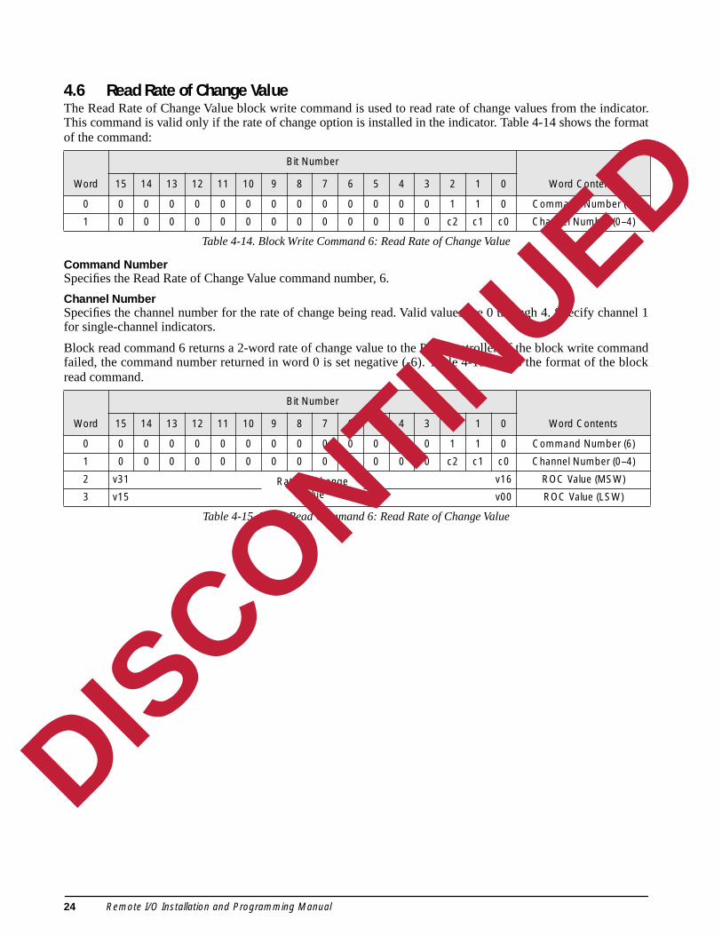
4.6 Read Rate of Change ValueThe Read Rate of Change Value block write command is used to read rate of change values from the iThis command is valid only if the rate of change option is installed in the indicator. Table 4-14 shows theof the command:
Table 4-14. Block Write Command 6: Read Rate of Change Value
Command NumberSpecifies the Read Rate of Change Value command number, 6.
Channel NumberSpecifies the channel number for the rate of change being read. Valid values are 0 through 4. Specify cfor single-channel indicators.
Block read command 6 returns a 2-word rate of change value to the PLC controller. If the block write comfailed, the command number returned in word 0 is set negative (-6). Table 4-15 shows the format of thread command.
Table 4-15. Block Read Command 6: Read Rate of Change Value
Word
Bit Number
Word Contents15 14 13 12 11 10 9 8 7 6 5 4 3 2 1 0
0 0 0 0 0 0 0 0 0 0 0 0 0 0 1 1 0 Command Number (6)
1 0 0 0 0 0 0 0 0 0 0 0 0 0 c2 c1 c0 Channel Number (0–4)
Word
Bit Number
Word Contents15 14 13 12 11 10 9 8 7 6 5 4 3 2 1 0
0 0 0 0 0 0 0 0 0 0 0 0 0 0 1 1 0 Command Number (6)
1 0 0 0 0 0 0 0 0 0 0 0 0 0 c2 c1 c0 Channel Number (0–4)
2 v31 Rate of Change Value
v16 ROC Value (MSW)
3 v15 v00 ROC Value (LSW)
DISCONTINUED
24 Remote I/O Installation and Programming Manual
ows the
el 1 for
ed, thek read
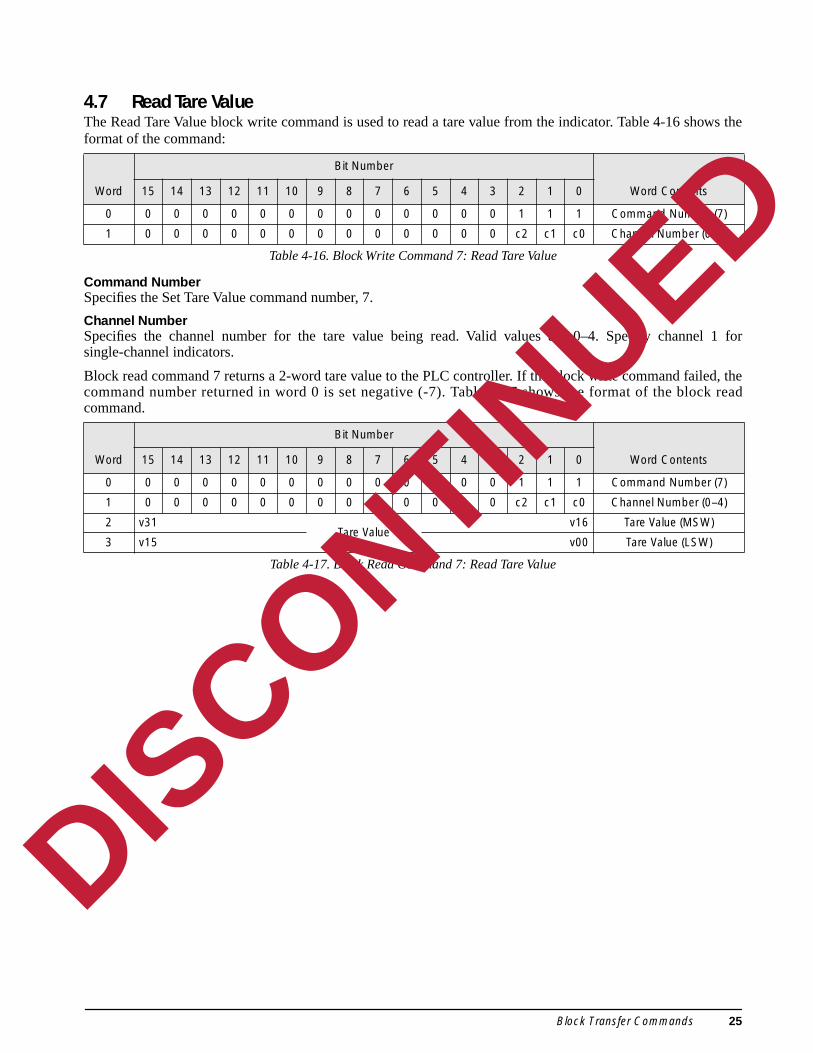
4.7 Read Tare ValueThe Read Tare Value block write command is used to read a tare value from the indicator. Table 4-16 shformat of the command:
Table 4-16. Block Write Command 7: Read Tare Value
Command NumberSpecifies the Set Tare Value command number, 7.
Channel NumberSpecifies the channel number for the tare value being read. Valid values are 0–4. Specify channsingle-channel indicators.
Block read command 7 returns a 2-word tare value to the PLC controller. If the block write command failcommand number returned in word 0 is set negative (-7). Table 4-17 shows the format of the bloccommand.
Table 4-17. Block Read Command 7: Read Tare Value
Word
Bit Number
Word Contents15 14 13 12 11 10 9 8 7 6 5 4 3 2 1 0
0 0 0 0 0 0 0 0 0 0 0 0 0 0 1 1 1 Command Number (7)
1 0 0 0 0 0 0 0 0 0 0 0 0 0 c2 c1 c0 Channel Number (0–4)
Word
Bit Number
Word Contents15 14 13 12 11 10 9 8 7 6 5 4 3 2 1 0
0 0 0 0 0 0 0 0 0 0 0 0 0 0 1 1 1 Command Number (7)
1 0 0 0 0 0 0 0 0 0 0 0 0 0 c2 c1 c0 Channel Number (0–4)
2 v31Tare Value
v16 Tare Value (MSW)
3 v15 v00 Tare Value (LSW)
DISCONTINUED
Block Transfer Commands 25

8 shows
nel 1 for
led, thek read
4.8 Read Gross ValueThe Read Gross Value block write command is used to read a gross value from the indicator. Table 4-1the format of the command:
Table 4-18. Block Write Command 8: Read Gross Value
Command NumberSpecifies the Read Gross Value command number, 8.
Channel NumberSpecifies the channel number for the gross value being read. Valid values are 0 through 4. Specify chansingle-channel indicators.
Block read command 8 returns a 2-word gross value to the PLC controller. If the block write command faicommand number returned in word 0 is set negative (-8). Table 4-19 shows the format of the bloccommand.
Table 4-19. Block Read Command 8: Read Gross Value
Word
Bit Number
Word Contents15 14 13 12 11 10 9 8 7 6 5 4 3 2 1 0
0 0 0 0 0 0 0 0 0 0 0 0 0 1 0 0 0 Command Number (8)
1 0 0 0 0 0 0 0 0 0 0 0 0 0 c2 c1 c0 Channel Number (0–4)
Word
Bit Number
Word Contents15 14 13 12 11 10 9 8 7 6 5 4 3 2 1 0
0 0 0 0 0 0 0 0 0 0 0 0 0 1 0 0 0 Command Number (8)
1 0 0 0 0 0 0 0 0 0 0 0 0 0 c2 c1 c0 Channel Number (0–4)
2 v31Gross Value
v16 Gross Value (MSW)
3 v15 v00 Gross Value (LSW)
DISCONTINUED
26 Remote I/O Installation and Programming Manual

ows the
nel 1 for
ed, thek read
4.9 Read Net ValueThe Read Net Value block write command is used to read a net value from the indicator. Table 4-20 shformat of the command:
Table 4-20. Block Write Command 9: Read Net Value
Command NumberSpecifies the Read Net Value command number, 9.
Channel NumberSpecifies the channel number for the net value being read. Valid values are 0 through 4. Specify chansingle-channel indicators.
Block read command 9 returns a 2-word net value to the PLC controller. If the block write command failcommand number returned in word 0 is set negative (-9). Table 4-21 shows the format of the bloccommand.
Table 4-21. Block Read Command 9: Read Net Value
Word
Bit Number
Word Contents15 14 13 12 11 10 9 8 7 6 5 4 3 2 1 0
0 0 0 0 0 0 0 0 0 0 0 0 0 1 0 0 1 Command Number (9)
1 0 0 0 0 0 0 0 0 0 0 0 0 0 c2 c1 c0 Channel Number (0–4)
Word
Bit Number
Word Contents15 14 13 12 11 10 9 8 7 6 5 4 3 2 1 0
0 0 0 0 0 0 0 0 0 0 0 0 0 1 0 0 1 Command Number (9)
1 0 0 0 0 0 0 0 0 0 0 0 0 0 c2 c1 c0 Channel Number (0–4)
2 v31Net Value
v16 Net Value (MSW)
3 v15 v00 Net Value (LSW)
DISCONTINUED
Block Transfer Commands 27
s for one
questedk write
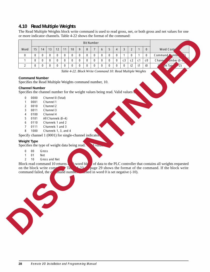
4.10 Read Multiple WeightsThe Read Multiple Weights block write command is used to read gross, net, or both gross and net valueor more indicator channels. Table 4-22 shows the format of the command:
Table 4-22. Block Write Command 10: Read Multiple Weights
Command NumberSpecifies the Read Multiple Weights command number, 10.
Channel NumberSpecifies the channel number for the weight values being read. Valid values are:
0 0000 Channel 0 (Total)1 0001 Channel 12 0010 Channel 23 0011 Channel 34 0100 Channel 45 0101 All Channels (0–4)6 0110 Channels 1 and 27 0111 Channels 1 and 38 1000 Channels 1, 3, and 4
Specify channel 1 (0001) for single-channel indicators.
Weight TypeSpecifies the type of weight data being read. Valid values are:
0 00 Gross1 01 Net2 10 Gross and Net
Block read command 10 returns a 23-word block of data to the PLC controller that contains all weights reon the block write command. Table 4-23 on page 29 shows the format of the command. If the bloccommand failed, the command number returned in word 0 is set negative (-10).
Word
Bit Number
Word Contents15 14 13 12 11 10 9 8 7 6 5 4 3 2 1 0
0 0 0 0 0 0 0 0 0 0 0 0 0 1 0 1 0 Command Number (10)
1 0 0 0 0 0 0 0 0 0 0 0 0 c3 c2 c1 c0 Channel Number (0–8)
2 0 0 0 0 0 0 0 0 0 0 0 0 0 t2 t1 t0 Weight Type (0–2)
DISCONTINUED
28 Remote I/O Installation and Programming Manual

Word
Bit Number
Word Contents15 14 13 12 11 10 9 8 7 6 5 4 3 2 1 0
0 0 0 0 0 0 0 0 0 0 0 0 0 1 0 1 0 Command Number (10)
1 0 0 0 0 0 0 0 0 0 0 0 0 c3 c2 c1 c0 Channel Number (0–8)
2 0 0 0 0 0 0 0 0 0 0 0 0 0 t2 t1 t0 Weight Type (0–2)
3 v31 Channel 0 Gross Value
v16 Ch 0 Gross Value (MSW)
4 v15 v00 Ch 0 Gross Value (LSW)
5 v31 Channel 1Gross Value
v16 Ch 1 Gross Value (MSW)
6 v15 v00 Ch 1 Gross Value (LSW)
7 v31 Channel 2Gross Value
v16 Ch 2 Gross Value (MSW)
8 v15 v00 Ch 2 Gross Value (LSW)
9 v31 Channel 3Gross Value
v16 Ch 3 Gross Value (MSW)
10 v15 v00 Ch 3 Gross Value (LSW)
11 v31 Channel 4Gross Value
v16 Ch 4 Gross Value (MSW)
12 v15 v00 Ch 4 Gross Value (LSW)
13 v31 Channel 0 Net Value
v16 Ch 0 Net Value (MSW)
14 v15 v00 Ch 0 Net Value (LSW)
15 v31 Channel 1Net Value
v16 Ch 1 Net Value (MSW)
16 v15 v00 Ch 1 Net Value (LSW)
17 v31 Channel 2Net Value
v16 Ch 2 Net Value (MSW)
18 v15 v00 Ch 2 Net Value (LSW)
19 v31 Channel 3Net Value
v16 Ch 3 Net Value (MSW)
20 v15 v00 Ch 3 Net Value (LSW)
21 v31 Channel 4Net Value
v16 Ch 4 Net Value (MSW)
22 v15 v00 Ch 4 Net Value (LSW)
Table 4-23. Block Read Command 10: Read Multiple Weights
DISCONTINUED
Block Transfer Commands 29
tpoints.ble 4-24
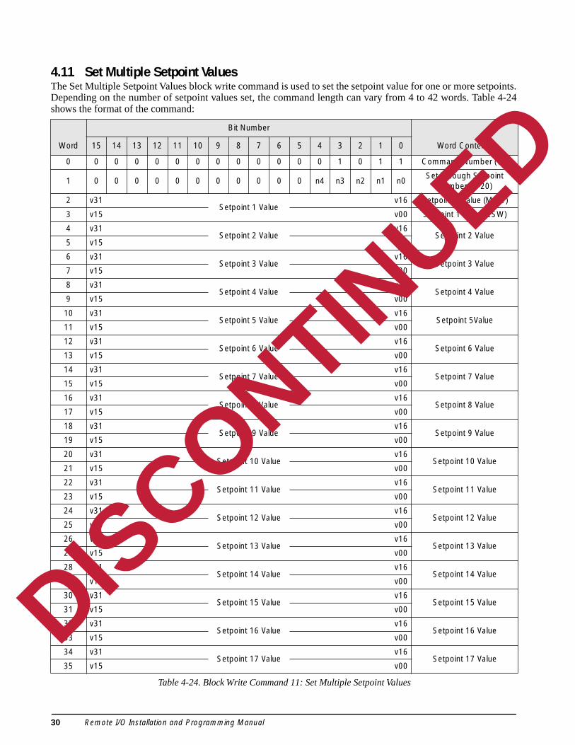
4.11 Set Multiple Setpoint ValuesThe Set Multiple Setpoint Values block write command is used to set the setpoint value for one or more seDepending on the number of setpoint values set, the command length can vary from 4 to 42 words. Tashows the format of the command:
Word
Bit Number
Word Contents15 14 13 12 11 10 9 8 7 6 5 4 3 2 1 0
0 0 0 0 0 0 0 0 0 0 0 0 0 1 0 1 1 Command Number (11)
1 0 0 0 0 0 0 0 0 0 0 0 n4 n3 n2 n1 n0Set Through Setpoint
Number (1–20)
2 v31Setpoint 1 Value
v16 Setpoint 1 Value (MSW)
3 v15 v00 Setpoint 1 Value (LSW)
4 v31Setpoint 2 Value
v16Setpoint 2 Value
5 v15 v00
6 v31Setpoint 3 Value
v16Setpoint 3 Value
7 v15 v00
8 v31Setpoint 4 Value
v16Setpoint 4 Value
9 v15 v00
10 v31Setpoint 5 Value
v16Setpoint 5Value
11 v15 v00
12 v31Setpoint 6 Value
v16Setpoint 6 Value
13 v15 v00
14 v31Setpoint 7 Value
v16Setpoint 7 Value
15 v15 v00
16 v31Setpoint 8 Value
v16Setpoint 8 Value
17 v15 v00
18 v31Setpoint 9 Value
v16Setpoint 9 Value
19 v15 v00
20 v31Setpoint 10 Value
v16Setpoint 10 Value
21 v15 v00
22 v31Setpoint 11 Value
v16Setpoint 11 Value
23 v15 v00
24 v31Setpoint 12 Value
v16Setpoint 12 Value
25 v15 v00
26 v31Setpoint 13 Value
v16Setpoint 13 Value
27 v15 v00
28 v31Setpoint 14 Value
v16Setpoint 14 Value
29 v15 v00
30 v31Setpoint 15 Value
v16Setpoint 15 Value
31 v15 v00
32 v31Setpoint 16 Value
v16Setpoint 16 Value
33 v15 v00
34 v31Setpoint 17 Value
v16Setpoint 17 Value
35 v15 v00
Table 4-24. Block Write Command 11: Set Multiple Setpoint Values
DISCONTINUED
30 Remote I/O Installation and Programming Manual
re set forber is 4,
Multiple
le 4-25
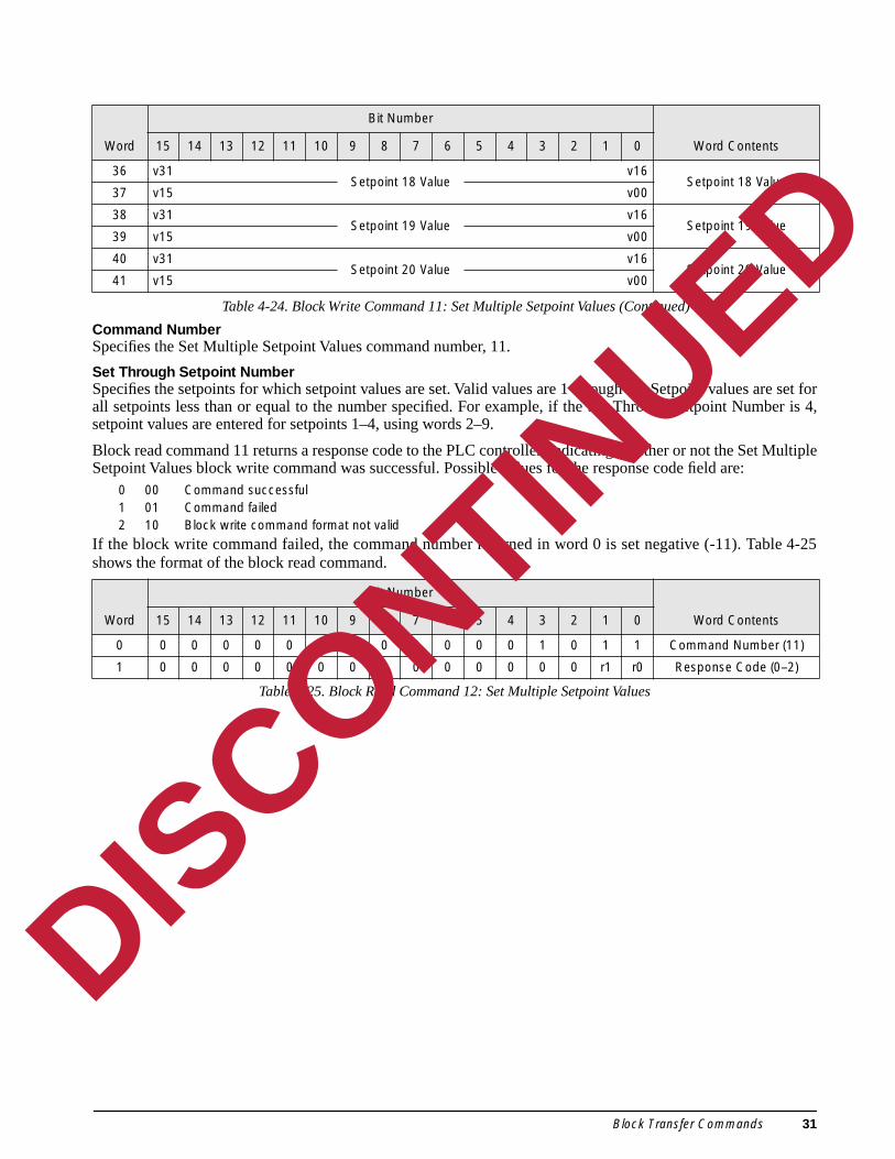
Command NumberSpecifies the Set Multiple Setpoint Values command number, 11.
Set Through Setpoint NumberSpecifies the setpoints for which setpoint values are set. Valid values are 1 through 20. Setpoint values aall setpoints less than or equal to the number specified. For example, if the Set Through Setpoint Numsetpoint values are entered for setpoints 1–4, using words 2–9.
Block read command 11 returns a response code to the PLC controller, indicating whether or not the Set Setpoint Values block write command was successful. Possible values for the response code field are:
0 00 Command successful1 01 Command failed2 10 Block write command format not valid
If the block write command failed, the command number returned in word 0 is set negative (-11). Tabshows the format of the block read command.
Table 4-25. Block Read Command 12: Set Multiple Setpoint Values
36 v31Setpoint 18 Value
v16Setpoint 18 Value
37 v15 v00
38 v31Setpoint 19 Value
v16Setpoint 19 Value
39 v15 v00
40 v31Setpoint 20 Value
v16Setpoint 20 Value
41 v15 v00
Word
Bit Number
Word Contents15 14 13 12 11 10 9 8 7 6 5 4 3 2 1 0
0 0 0 0 0 0 0 0 0 0 0 0 0 1 0 1 1 Command Number (11)
1 0 0 0 0 0 0 0 0 0 0 0 0 0 0 r1 r0 Response Code (0–2)
Word
Bit Number
Word Contents15 14 13 12 11 10 9 8 7 6 5 4 3 2 1 0
Table 4-24. Block Write Command 11: Set Multiple Setpoint Values (Continued)
DISCONTINUED
Block Transfer Commands 31
r more
lues areSetpoint
response can varyd.
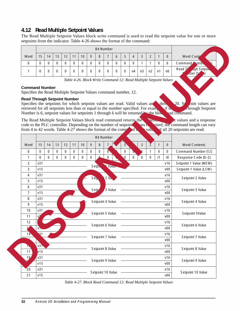
4.12 Read Multiple Setpoint ValuesThe Read Multiple Setpoint Values block write command is used to read the setpoint value for one osetpoints from the indicator. Table 4-26 shows the format of the command:
Table 4-26. Block Write Command 12: Read Multiple Setpoint Values
Command NumberSpecifies the Read Multiple Setpoint Values command number, 12.
Read Through Setpoint NumberSpecifies the setpoints for which setpoint values are read. Valid values are 1 through 20. Setpoint varetrieved for all setpoints less than or equal to the number specified. For example, if the Read Through Number is 6, setpoint values for setpoints 1 through 6 will be returned by the block read command.
The Read Multiple Setpoint Values block read command returns the requested setpoint values and a code to the PLC controller. Depending on the number of setpoint values requested, the command lengthfrom 4 to 42 words. Table 4-27 shows the format of the command if the values of all 20 setpoints are rea
Word
Bit Number
Word Contents15 14 13 12 11 10 9 8 7 6 5 4 3 2 1 0
0 0 0 0 0 0 0 0 0 0 0 0 0 1 1 0 0 Command Number (12)
1 0 0 0 0 0 0 0 0 0 0 0 n4 n3 n2 n1 n0Read Through Setpoint
Number (1–20)
Word
Bit Number
Word Contents15 14 13 12 11 10 9 8 7 6 5 4 3 2 1 0
0 0 0 0 0 0 0 0 0 0 0 0 0 1 1 0 0 Command Number (12)
1 0 0 0 0 0 0 0 0 0 0 0 0 0 0 r1 r0 Response Code (0–2)
2 v31Setpoint 1 Value
v16 Setpoint 1 Value (MSW)
3 v15 v00 Setpoint 1 Value (LSW)
4 v31Setpoint 2 Value
v16Setpoint 2 Value
5 v15 v00
6 v31Setpoint 3 Value
v16Setpoint 3 Value
7 v15 v00
8 v31Setpoint 4 Value
v16Setpoint 4 Value
9 v15 v00
10 v31Setpoint 5 Value
v16Setpoint 5Value
11 v15 v00
12 v31Setpoint 6 Value
v16Setpoint 6 Value
13 v15 v00
14 v31Setpoint 7 Value
v16Setpoint 7 Value
15 v15 v00
16 v31Setpoint 8 Value
v16Setpoint 8 Value
17 v15 v00
18 v31Setpoint 9 Value
v16Setpoint 9 Value
19 v15 v00
20 v31Setpoint 10 Value
v16Setpoint 10 Value
21 v15 v00
Table 4-27. Block Read Command 12: Read Multiple Setpoint Values
DISCONTINUED
32 Remote I/O Installation and Programming Manual
nd was
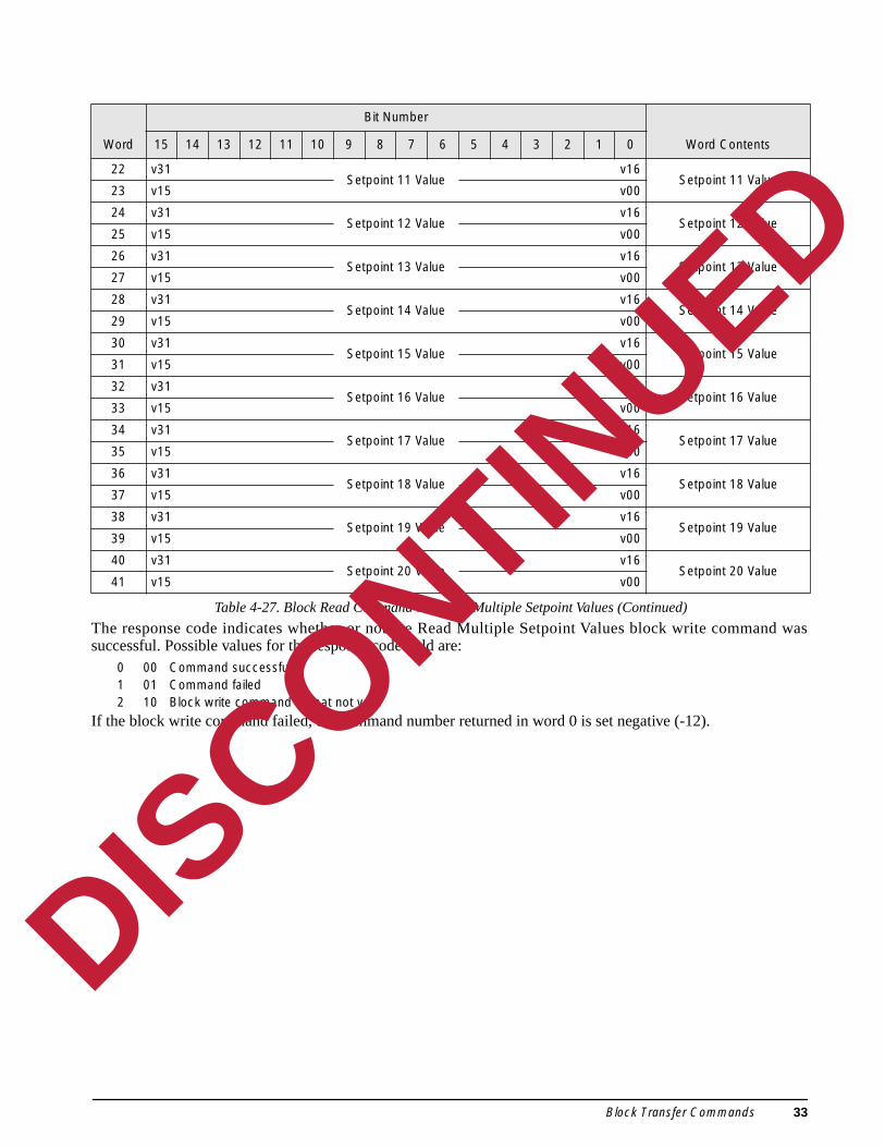
The response code indicates whether or not the Read Multiple Setpoint Values block write commasuccessful. Possible values for the response code field are:0 00 Command successful1 01 Command failed2 10 Block write command format not valid
If the block write command failed, the command number returned in word 0 is set negative (-12).
22 v31Setpoint 11 Value
v16Setpoint 11 Value
23 v15 v00
24 v31Setpoint 12 Value
v16Setpoint 12 Value
25 v15 v00
26 v31Setpoint 13 Value
v16Setpoint 13 Value
27 v15 v00
28 v31Setpoint 14 Value
v16Setpoint 14 Value
29 v15 v00
30 v31Setpoint 15 Value
v16Setpoint 15 Value
31 v15 v00
32 v31Setpoint 16 Value
v16Setpoint 16 Value
33 v15 v00
34 v31Setpoint 17 Value
v16Setpoint 17 Value
35 v15 v00
36 v31Setpoint 18 Value
v16Setpoint 18 Value
37 v15 v00
38 v31Setpoint 19 Value
v16Setpoint 19 Value
39 v15 v00
40 v31Setpoint 20 Value
v16Setpoint 20 Value
41 v15 v00
Word
Bit Number
Word Contents15 14 13 12 11 10 9 8 7 6 5 4 3 2 1 0
Table 4-27. Block Read Command 12: Read Multiple Setpoint Values (Continued)
DISCONTINUED
Block Transfer Commands 33

AUTO,
the Set
le 4-29
4.13 Set Batching StateThe Set Batching State block write command is used to set the batching (BATCHNG) parameter to OFF,or MANUAL. Table 4-28 shows the format of the command:
Table 4-28. Block Write Command 13: Set Batching State
Command NumberSpecifies the Set Batching State command number, 13.
Batching StateSpecifies the type of batching enabled for the indicator. Possible values are:
0 00 Off1 01 Automatic2 10 Manual
The block read command returns a response code to the PLC controller, indicating whether or notBatching State block write command was successful. Possible values for the response code field are:
0 00 Command successful1 01 Command failed2 10 Block write command format not valid
If the block write command failed, the command number returned in word 0 is set negative (–13). Tabshows the format of the block read command.
Table 4-29. Block Read Command 13: Set Batching State
Word
Bit Number
Word Contents15 14 13 12 11 10 9 8 7 6 5 4 3 2 1 0
0 0 0 0 0 0 0 0 0 0 0 0 0 1 1 0 1 Command Number (13)
1 0 0 0 0 0 0 0 0 0 0 0 0 0 0 s1 s0 Batching State (0–2)
Word
Bit Number
Word Contents15 14 13 12 11 10 9 8 7 6 5 4 3 2 1 0
0 0 0 0 0 0 0 0 0 0 0 0 0 1 1 0 1 Command Number (13)
1 0 0 0 0 0 0 0 0 0 0 0 0 0 0 r1 r0 Response Code (0–2)
DISCONTINUED
34 Remote I/O Installation and Programming Manual

rface.
ce andexampleer 0.
ote I/O
d has
5.0 OperationThe examples on the following pages provide PLC programming examples for using the Remote I/O Inte
5.1 Test Program for Verifying Remote I/O Interface OperationThe following programming example writes a series of discrete commands to the Remote I/O Interfachecks the status bits returned in the input image table to confirm completion of each command. This assumes the Remote I/O scanner to be in slot #2, with the Remote I/O Interface at rack address 0, quart
NOTES:
1. This program can be edited and used to test communications between the PLC and the RemInterface.
2. The COMMAND WORD must be zeroed after checking the status bits to confirm that the commanbeen executed.
DISCONTINUED
Operation 35

MOV
MoveSource 0Dest O:2.1 0
MOV
MoveSource 9Dest O:2.1 0
MoveSource 6Dest O:2.1 0
MoveSource 7Dest O:2.1 0
MoveSource 21Dest O:2.1 0
COMMAND WORD
COMMAND WORD
MOV
COMMAND WORD
MOV
COMMAND WORD
MOV
COMMAND WORD
S2:1
B3
0
15
B3
B3
B3
1
2
3
0
1
2
3
4
5 MoveSource 0Dest O:2.1 0
MOV
COMMAND WORD
JSR
Jump To SubroutineSBR File Number U:8
CONVERT
6
7 [END]
B3
0
(U)
B3
1
(U)
B3
2
(U)
B3
3
(U)
TARE SCALE
DISPLAYGROSS WEIGHT
DISPLAYNET WEIGHT
CLEAR TARE
B3
0
I:2.1
9
B3
1
I:2.1
8
B3
2
I:2.1
8
B3
3
I:2.1
9
TARE SCALE SCALE TARE STATUS
DISPLAYGROSS WEIGHT
GROSS/NETSTATUS
DISPLAYNET WEIGHT
GROSS/NETSTATUS
CLEAR TARESCALE TARESTATUS
MONITOR STATUS BITS TO CONFIRM EACH TASK IS PERFORMED,THEN CLEAR DISCRETE WRITE OUTPUT
CLEAR DISCRETE WRITE OUTPUT COMMAND
IF TARE BIT IS SET, SEND TARE COMMAND TO DISCRETE WRITE OUTPUT
TARE SCALE
DISPLAY GROSS WEIGHT
DISPLAY NET WEIGHT
CLEAR TARE
IF GROSS BIT IS SET, SET SCALE TO GROSS MODE
IF NET BIT IS SET, SET SCALE TO NET MODE
IF CLEAR TARE BIT IS SET, CLEAR TARE VALUE
FIRST PASS
DISCONTINUED
36 Remote I/O Installation and Programming Manual
r value
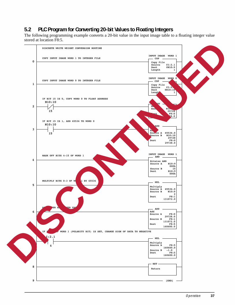
5.2 PLC Program for Converting 20-bit Values to Floating IntegersThe following programming example converts a 20-bit value in the input image table to a floating integestored at location F8:5.COP
Copy FileSource #I:2.1Dest #N10:9Length 1
COP
Copy FileSource #I:2.0Dest #N10:10Length 1
MoveSource N10:10 29728Dest F8:0 29728.0
AddSource A 65536.0Source B N10:10 29728Dest F8:0 29728.0
INPUT IMAGE WORD 1
INPUT IMAGE WORD 0
MOV
ADD
N10:10
15
0
1
2
3
4
5
8
9 [END]
I:2.1
4
IF BIT 4 OF WORD 1 (POLARITY BIT) IS SET, CHANGE SIGN OF DATA TO NEGATIVE
DISCRETE WRITE WEIGHT CONVERSION ROUTINE
COPY INPUT IMAGE WORD 1 TO INTEGER FILE
COPY INPUT IMAGE WORD 0 TO INTEGER FILE
IF BIT 15 IS 0, COPY WORD 0 TO FLOAT ADDRESS
N10:10
15
IF BIT 15 IS 1, ADD 65536 TO WORD 0
RET
Return
MultiplySource A F8:5 160600.0Source B -1.0Dest F8:5 160600.0
MUL7
Bitwise ANDSource A N10:9 000h
Source B 15Dest N10:9 000h
AND
MultiplySource A 65536.0Source B N10:9 2Dest F8:1 131072.0
MUL
AddSource A F8:0 29728.0Source B F8:1 131072.0Dest F8:5 160600.0
ADD
INPUT IMAGE WORD 1
6
ADD UPPER AND LOWER VALUES
MULTIPLY BITS 0-3 OF WORD 1 BY 65536
MASK OFF BITS 4-15 OF WORD 1
DISCONTINUED
Operation 37
00/810k reades block
pond to
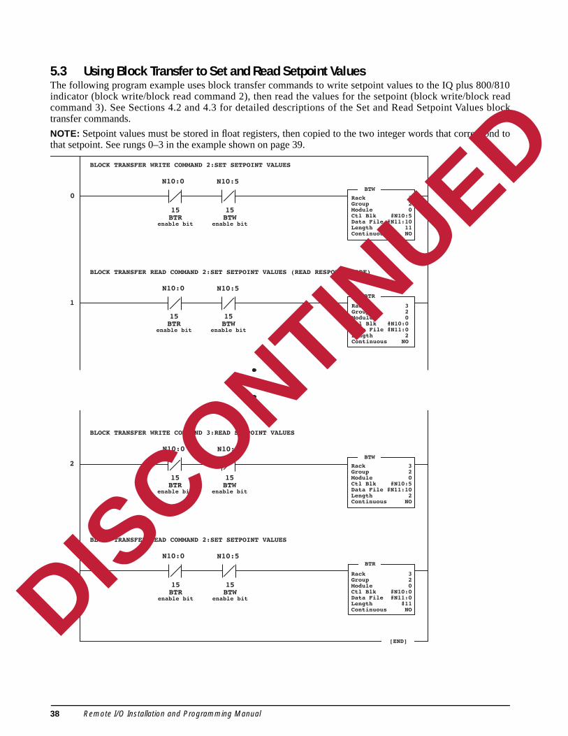
5.3 Using Block Transfer to Set and Read Setpoint ValuesThe following program example uses block transfer commands to write setpoint values to the IQ plus 8indicator (block write/block read command 2), then read the values for the setpoint (block write/bloccommand 3). See Sections 4.2 and 4.3 for detailed descriptions of the Set and Read Setpoint Valutransfer commands.
NOTE: Setpoint values must be stored in float registers, then copied to the two integer words that corresthat setpoint. See rungs 0–3 in the example shown on page 39.
[END]
BTW
Rack 3Group 2Module 0Ctl Blk #N10:5Data File #N11:10Length 11Continuous NO
1BTR
Rack 3Group 2Module 0Ctl Blk #N10:0Data File #N11:0Length 2Continuous NO
BTW
Rack 3Group 2Module 0Ctl Blk #N10:5Data File #N11:10Length 2Continuous NO
2
BTR
Rack 3Group 2Module 0Ctl Blk #N10:0Data File #N11:0Length #11Continuous NO
N10:0 N10:5
15BTR
enable bit
15BTW
enable bit
N10:0 N10:5
15BTR
enable bit
15BTW
enable bit
N10:0 N10:5
15BTR
enable bit
15BTW
enable bit
N10:0 N10:5
15BTR
enable bit
15BTW
enable bit
0
3
BLOCK TRANSFER WRITE COMMAND 2:SET SETPOINT VALUES
BLOCK TRANSFER READ COMMAND 2:SET SETPOINT VALUES (READ RESPONSE CODE)
BLOCK TRANSFER READ COMMAND 2:SET SETPOINT VALUES
BLOCK TRANSFER WRITE COMMAND 3:READ SETPOINT VALUES
DISCONTINUED
38 Remote I/O Installation and Programming Manual

s beforerted backSet and
Floating point values used for the Set Setpoint Values parameters must be copied into separate wordissuing the command. Values returned on the Read Setpoint Values block read command must be conveto floating point values. The following example shows these conversions for all four parameters on the Read Setpoint Values commands.
7
[END]
0 COPCopy FileSource #F8:1Dest #N11:13Length 2
COPCopy FileSource #N11:19Dest #F8:4Length 1
COPY FLOATING POINT SETPOINT VALUE INTO TWO SEPARATE WORDS
CONVERT 2-WORD PREACT VALUE TO FLOATING POINT VALUE
1 COPCopy FileSource #F8:2Dest #N11:15Length 2
COPY FLOATING POINT BAND VALUE INTO TWO SEPARATE WORDS
2 COPCopy FileSource #F8:3Dest #N11:17Length 2
COPY FLOATING POINT HYSTERESIS VALUE INTO TWO SEPARATE WORDS
3 COPCopy FileSource #F8:4Dest #N11:19Length 2
COPY FLOATING POINT PREACT VALUE INTO TWO SEPARATE WORDS
6 COPCopy FileSource #N11:17Dest #F8:3Length 1
CONVERT 2-WORD HYSTERESIS VALUE TO FLOATING POINT VALUE
5 COPCopy FileSource #N11:15Dest #F8:2Length 1
CONVERT 2-WORD BAND VALUE TO FLOATING POINT VALUE
4 COPCopy FileSource #N11:13Dest #F8:1Length 1
CONVERT 2-WORD SETPOINT VALUE TO FLOATING POINT VALUE
(SET SETPOINT VALUES, READ SETPOINT VALUES BLOCK TRANSFER COMMANDS)
DISCONTINUED
Operation 39
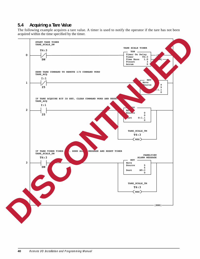
t been
5.4 Acquiring a Tare ValueThe following example acquires a tare value. A timer is used to notify the operator if the tare has noacquired within the time specified by the timer.TONTimer On DelayTimer T4:3Time Base 1.0Preset 3Accum 0
TARE SCALE TIMER
0
1
2
3
4
START TARE TIMERTARE_SCALE_DN
SEND TARE COMMAND TO REMOTE I/O COMMAND WORDTARE_ACQ
T4:3
DN
[EN]
[DN]
I:1
25
MOVMoveSource 9
9Dest O:1.1
0
25
MOVMoveSource 0
0Dest O:1.1
0
I:1
IF TARE ACQUIRE BIT IS SET, CLEAR COMMAND WORD AND RESET TIMERTARE_ACQ
TARE_SCALE_TM
T4:3
RES
DN
MOVMoveSource 5
5Dest N9:3
0
T4:3
IF TARE TIMER TIMES OUT, SEND ALARM MESSAGE AND RESET TIMERTARE_SCALE_DN
TARE_SCALE_TM
T4:3
RES
[END]
PANELVIEWALARM MESSAGE
DISCONTINUED
40 Remote I/O Installation and Programming Manual

rom two
5.5 Reading Weights from Multiple Scale ChannelsThe following programming example uses a timer and the channel status bit (s02) to read net weights fscale channels.TONTimer On DelayTimer T4:3Time Base 0.01Preset 50Accum 1
MOV
CHANNEL CHANGE TIMER
MOV
MOV
0
1
2
3
4
RUN TIMER
SEND NET COMMAND FOR CHANNEL 1 WHILE TIMER IS IN RANGE
I1:1
23
TEST STATUS BIT WHEN NOT SET AND TIMER ACC=24,CAPTURE WEIGHT VALUE FOR SCALE 1
MOVSCALE_2_WT
T4:3
DN
MoveSource 28
28Dest O:1.1
28
MoveSource 29
29Dest O:1.1
28
MoveSource I1.0
1087Dest N7:100
1087
MoveSource I1.0
353Dest N7:101
353
SCALE_1_WT
I:1
23
TEST STATUS BIT WHEN SET AND TIMER ACC=49,CAPTURE WEIGHT VALUE FOR SCALE 2
SEND NET COMMAND FOR CHANNEL 2 WHILE TIMER IS IN RANGE
EQU
EqualSource A T4:3.ACC
1Source B 24
24
EQU
EqualSource A T4:3.ACC
1Source B 49
49
LIMLimit TestLow Lim 26
26Test 1High Lim 50
50
LIMLimit TestLow Lim 0
0Test T4:3.ACCHigh Lim 25
25
[EN]
[DN]
[END]5
DISCONTINUED
Operation 41

oblems.e PLC
te I/O
r your
6.0 TroubleshootingThe LED indicators on the Remote I/O Interface can be used to isolate hardware and configuration prThe LEDs show whether the problem exists in the connection to the indicator, the connection to thcontroller, or the Remote I/O Interface itself.
The flowchart on the following page provides a diagnostic procedure for troubleshooting the RemoInterface using the unit’s LED indicators.
If all LEDs appear to be responding correctly, edit the program shown in Section 5.1 on page 35 foinstallation and use it to test the Remote I/O Interface.
DISCONTINUED
42 Remote I/O Installation and Programming Manual

START PLC Program
POWERLED state?
Unit plugged in andpower available at
outlet?
OFF
NO
YESProbable bad power supply
Call RLWS Service
ON
RIOLED state?
ON
OFF
Probable bad EPROMCall RLWS Service
FLASHING
No communication with RIO network
Check network connections to J5
Check DIP switch configuration for:Network data rate (SW2-1 and SW2-2)Last rack (SW2-3)Starting quarter (SW1-1 and SW1-2)Rack address (SW1-3 through SW1-8)
FLASHINGPlace PLC/SLC controllerin RUN mode
RxDLED state?
OFF
No communication with indicator
Check indicator connections to J4
Check indicator configuration and mode
Verify indicator is receiving signal fromload cell or simulator
ON (almost continuous)
NOTE: RxD LED will be ON steady if 20mA optionis installed but indicator is not connected
TxDLED state?
FLASHINGat 1 sec intervals No response from indicator
Check indicator configuration
Check DIP switch SW2-5 for correctindicator type
NOTE: Ensure that jumper JU1 is set for the correct termination resistance value
FLASHINGwith each command sent
from PLC controller
Load and edit test program shown inRemote I/O Interface Installation
and Programming Manual
Run test program
Does test programwork
as expected?
YES NOProbable PLC programming errorin original program
Call RLWS Software Supportfor assistance if necessary
Possible hardware problemor configuration error
Call RLWS Service if necessary
Note: Commands 0 and 45 are not passed to theindicator. TxD LED will not flash when thesecommands are executed.
Note: Valid commands must be entered intothe command output word to test TxD LED status
No communication with indicator
Check connections at indicator
ON (continuous)
DISCONTINUED
Troubleshooting 43

gic
d. s.0. rd
k on
wsn
e.
7.0 Power Supply BoardTwo circumstances may require servicing the powersupply board in the field:
• Power supply fuse replacement• Conversion from 115 to 230 (or 230 to 115)
VAC operationBoth operations require opening the enclosure andremoving the logic board to access the power supplyboard. Figure 7-1 shows the layout of the powersupply board, including the locations of the powersupply fuses (F1 and F2) and the jumpers used toselect operating voltage (JU1–JU3).
7.1 Fuse ReplacementUse the following procedure to replace fuses on theRemote I/O Interface power supply board:
1. Disconnect Remote I/O Interface from powersource.
Use a wrist strap to ground yourself andprotect components from electrostaticdischarge (ESD) when working inside theRemote I/O Interface enclosure.
2. Remove enclosure cover.3. Disconnect cables at J1 and J3 on the lo
board (see Figure 2-2 on page 2).4. Disconnect indicator and A-B network
connections at J4 and J5 (see Figure 2-2).5. Remove nuts from stand-offs in logic boar
corners, then lift logic board out of enclosure6. Remove blown fuses from fuse socket
Replace with fuses as specified in Section 8.7. Replace circuit board, reinstall nuts on boa
stand-offs. 8. Reconnect cables at J1 and J3.9. Reconnect indicator and A-B networ
connections at J4 and J5 (see Section 2.1.2page 3).
10. Replace enclosure cover and tighten screusing torquing pattern shown in Figure 2-1 opage 2.
11. Reconnect power to the Remote I/O Interfac
Figure 7-1. Remote I/O Power Supply Board
! Caution
JU4
JU5C12
JU1
JU2
JU3
115
115
230
+
D1
+
R15
R1
C2
C1
CR
1
F2
F1
1J1
AC1 –
AC2 +
GND
T1
DISCONTINUED
44 Remote I/O Installation and Programming Manual

or.ct
erd
7.2 Operating Voltage ConversionThe Remote I/O Interface is normally set up for either115 or 230 VAC operation before it is shipped. If theunit must be converted to a different operating voltagein the field, do the following:
1. Follow steps 1–5 of the fuse replacementprocedure (Section 7.1 on page 44) to openthe enclosure and remove the logic board.
2. Remove four 1.5-in. stand-offs from eachcorner of the power supply board.
3. Disconnect AC power connections on powersupply board (AC+, AC–, and GND inFigure 7-1 on page 44), then lift board out ofenclosure.
4. Change the jumper configuration for the newoperating voltage. Figure 7-2 shows thejumper configurations for 115 and 230 VACoperation.When converting from 115 to 230 VACoperation, clip jumpers JU1 and JU2 close tothe pad, then solder one of the jumper wiresacross JU3. If converting to 115 VAC, or ifnew jumper wire must be used, use tinnedAWG #22 wire for the jumpers. Ensure newlyinstalled jumper wire does not extend belowthe power supply board.
5. Remove old fuses. Install fuses specified fthe new operating voltage (see Section 8.0)
6. Replace power supply board and reconneAC power connections.
7. Reinstall stand-offs.8. Continue with steps 7–11 of the fus
replacement procedure to reinstall logic boaand reconnect the Remote I/O Interface.
Figure 7-2. Jumper Configuration for 115 and 230 VACOperation
JU1
JU2
JU3
JU1
JU2
JU3
115 VAC 230 VAC
DISCONTINUED
Power Supply Board 45
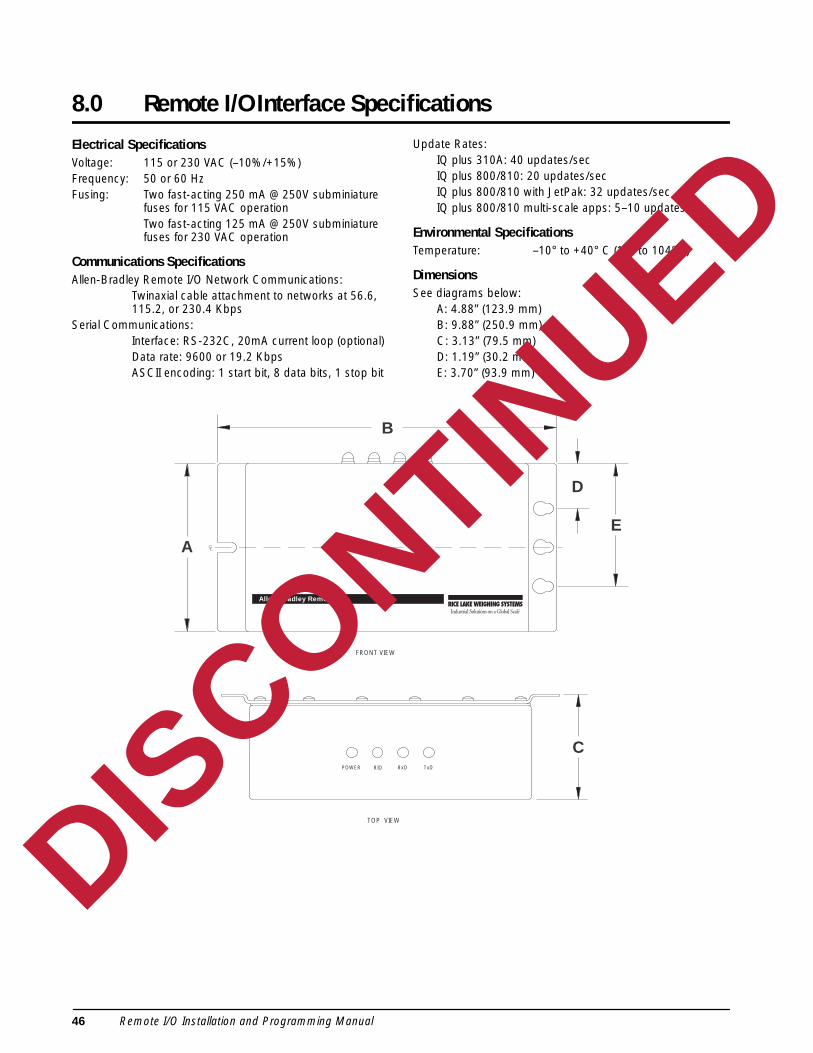
8.0 Remote I/O Interface Specifications
Electrical SpecificationsVoltage: 115 or 230 VAC (–10%/+15%)Frequency: 50 or 60 HzFusing: Two fast-acting 250 mA @ 250V subminiature
fuses for 115 VAC operationTwo fast-acting 125 mA @ 250V subminiature fuses for 230 VAC operation
Communications SpecificationsAllen-Bradley Remote I/O Network Communications:
Twinaxial cable attachment to networks at 56.6, 115.2, or 230.4 Kbps
Serial Communications:Interface: RS-232C, 20mA current loop (optional)Data rate: 9600 or 19.2 KbpsASCII encoding: 1 start bit, 8 data bits, 1 stop bit
Update Rates:IQ plus 310A: 40 updates/secIQ plus 800/810: 20 updates/secIQ plus 800/810 with JetPak: 32 updates/secIQ plus 800/810 multi-scale apps: 5–10 updates/sec
Environmental SpecificationsTemperature: –10° to +40° C (14° to 104° F)
DimensionsSee diagrams below:
A: 4.88” (123.9 mm)B: 9.88” (250.9 mm)C: 3.13” (79.5 mm)D: 1.19” (30.2 mm)E: 3.70” (93.9 mm)
FRONT VIEW
Allen-Bradley Remote I/O
A
B
D
E
RxDPOWER RIO TxD
TOP VIEW
C
DISCONTINUED
46 Remote I/O Installation and Programming Manual

d by aed byfects in
orizedipmenthin the
toin aS
as or
r its
ible
r
Remote I/O Interface Limited WarrantyRice Lake Weighing Systems (RLWS) warrants that all RLWS equipment and systems properly installeDistributor or Original Equipment Manufacturer (OEM) will operate per written specifications as confirmthe Distributor/OEM and accepted by RLWS. All systems and components are warranted against dematerials and workmanship for one year.
RLWS warrants that the equipment sold hereunder will conform to the current written specifications authby RLWS. RLWS warrants the equipment against faulty workmanship and defective materials. If any equfails to conform to these warranties, RLWS will, at its option, repair or replace such goods returned witwarranty period subject to the following conditions:
• Upon discovery by Buyer of such nonconformity, RLWS will be given prompt written notice with adetailed explanation of the alleged deficiencies.
• Individual electronic components returned to RLWS for warranty purposes must be packagedprevent electrostatic discharge (ESD) damage in shipment. Packaging requirements are listed publication, “Protecting Your Components From Static Damage in Shipment,” available from RLWEquipment Return Department.
• Examination of such equipment by RLWS confirms that the nonconformity actually exists, and wnot caused by accident, misuse, neglect, alteration, improper installation, improper repairimproper testing; RLWS shall be the sole judge of all alleged non-conformities.
• Such equipment has not been modified, altered, or changed by any person other than RLWS oduly authorized repair agents.
• RLWS will have a reasonable time to repair or replace the defective equipment. Buyer is responsfor shipping charges both ways.
• In no event will RLWS be responsible for travel time or on-location repairs, including assembly odisassembly of equipment, nor will RLWS be liable for the cost of any repairs made by others.
THESE WARRANTIES EXCLUDE ALL OTHER WARRANTIES , EXPRESSED OR IMPLIED , INCLUDINGWITHOUT LIMITATION WARRANTIES OF MERCHANTABILITY OR FITNESS FOR A PARTICULARPURPOSE . NEITHER RLWS NOR DISTRIBUTOR WILL , IN ANY EVENT , BE LIABLE FOR INCIDENTALOR CONSEQUENTIAL DAMAGES .
RLWS AND BUYER AGREE THAT RLWS’ S SOLE AND EXCLUSIVE LIABILITY HEREUNDER ISLIMITED TO REPAIR OR REPLACEMENT OF SUCH GOODS . IN ACCEPTING THIS WARRANTY , THEBUYER WAIVES ANY AND ALL OTHER CLAIMS TO WARRANTY .
SHOULD THE SELLER BE OTHER THAN RLWS, THE BUYER AGREES TO LOOK ONLY TO THE SELLERFOR WARRANTY CLAIMS .
NO TERMS , CONDITIONS , UNDERSTANDING , OR AGREEMENTS PURPORTING TO MODIFY THETERMS OF THIS WARRANTY SHALL HAVE ANY LEGAL EFFECT UNLESS MADE IN WRITING ANDSIGNED BY A CORPORATE OFFICER OF RLWS AND THE BUYER .
© 2000 Rice Lake Weighing Systems, Inc. Rice Lake, WI USA. All Rights Reserved.
RICE LAKE WEIGHING SYSTEMS • 230 WEST COLEMAN STREET • RICE LAKE, WISCONSIN 54868 • USA
DISCONTINUED
Remote I/O Interface Specifications 47


