WE GLADLY ACCEPT VISA AND MASTERCARDW I R E , I N C .
I S O9 0 0 1 : 2 0 0 8C ER T I F I ED
H I S OA S 9 0 0 1 CR E V . CC E R T I F I E D P E N D I N G
H E L I C A L W I R E I N CT A B L E
O F C O N T E N T S
Manu f a c t u r i n g
Ma t e r i a l s a n d F i n i s h e s
S t a n d a r d B u l k I n s e r t s , N o n - L o c k i n g
S t a n d a r d B u l k I n s e r t s , L o c k i n g
Te c h n i c a l I n f o rma t i o n , S t a n d a r d
Te c h n i c a l I n f o rma t i o n , M e t r i c
M e t r i c B u l k , N o n - L o c k i n g
Me t r i c B u l k , L o c k i n g
D r i l l i n g
Ta p p i n g
T h r e a d G a g e s
I n s t a l l a t i o n To o l s
B o l t T y p e
C a p t i v e S l e e v e
Remo v a b l e S l e e v e
Powe r To o l s
S t r i p F e e d
Ta n g B r e a k - O f f To o l s
E x t r a c t i o n To o l s
R e p a i r K i t s
O v e r s i z e I n s e r t s
D o u b l e - s e r t s
S p e c i a l s
8 - P i t c h
C omme r c i a l G r a d e
2
3
4
10
14
17
20
23
26
28
34
36
37
38
39
41
46
47
49
50
54
56
61
62
64
TABLE
OF
CONTENTS
3
H E L I C A L W I R E I N C
2
M A T E R I A L S A N D F I N I S H E S
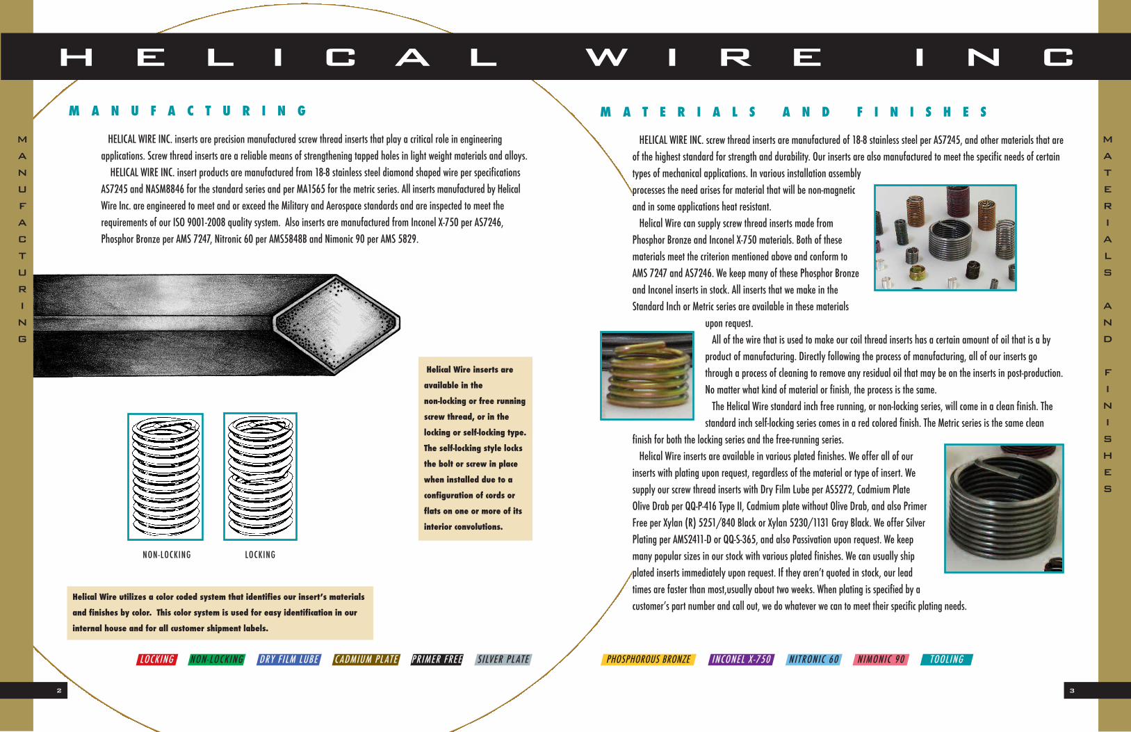
HELICAL WIRE INC. screw thread inserts are manufactured of 18-8 stainless steel per AS7245, and other materials that areof the highest standard for strength and durability. Our inserts are also manufactured to meet the specific needs of certaintypes of mechanical applications. In various installation assemblyprocesses the need arises for material that will be non-magneticand in some applications heat resistant.Helical Wire can supply screw thread inserts made from
Phosphor Bronze and Inconel X-750 materials. Both of these materials meet the criterion mentioned above and conform toAMS 7247 and AS7246. We keep many of these Phosphor Bronzeand Inconel inserts in stock. All inserts that we make in the Standard Inch or Metric series are available in these materials
upon request.All of the wire that is used to make our coil thread inserts has a certain amount of oil that is a by
product of manufacturing. Directly following the process of manufacturing, all of our inserts gothrough a process of cleaning to remove any residual oil that may be on the inserts in post-production.No matter what kind of material or finish, the process is the same.The Helical Wire standard inch free running, or non-locking series, will come in a clean finish. The
standard inch self-locking series comes in a red colored finish. The Metric series is the same clean finish for both the locking series and the free-running series.Helical Wire inserts are available in various plated finishes. We offer all of our
inserts with plating upon request, regardless of the material or type of insert. We supply our screw thread inserts with Dry Film Lube per AS5272, Cadmium Plate Olive Drab per QQ-P-416 Type II, Cadmium plate without Olive Drab, and also PrimerFree per Xylan (R) 5251/840 Black or Xylan 5230/1131 Gray Black. We offer SilverPlating per AMS2411-D or QQ-S-365, and also Passivation upon request. We keepmany popular sizes in our stock with various plated finishes. We can usually shipplated inserts immediately upon request. If they aren’t quoted in stock, our leadtimes are faster than most,usually about two weeks. When plating is specified by acustomer’s part number and call out, we do whatever we can to meet their specific plating needs.
HELICAL WIRE INC. inserts are precision manufactured screw thread inserts that play a critical role in engineering applications. Screw thread inserts are a reliable means of strengthening tapped holes in light weight materials and alloys.HELICAL WIRE INC. insert products are manufactured from 18-8 stainless steel diamond shaped wire per specifications
AS7245 and NASM8846 for the standard series and per MA1565 for the metric series. All inserts manufactured by HelicalWire Inc. are engineered to meet and or exceed the Military and Aerospace standards and are inspected to meet the requirements of our ISO 9001-2008 quality system. Also inserts are manufactured from Inconel X-750 per AS7246, Phosphor Bronze per AMS 7247, Nitronic 60 per AMS5848B and Nimonic 90 per AMS 5829.
M A N U F A C T U R I N G
Helical Wire inserts are
available in the
non-locking or free running
screw thread, or in the
locking or self-locking type.
The self-locking style locks
the bolt or screw in place
when installed due to a
configuration of cords or
flats on one or more of its
interior convolutions.
MATERIAL S
AND
FINISHES
MANUFACT URING
LOCKINGNON-LOCKING
PHOSPHOROUS BRONZE INCONEL X -750 NITRONIC 60CADMIUM PL ATE SILVER PL ATEDRY F ILM LUBE PRIMER FREELOCKING NON-LOCKING NIMONIC 90 TOOLING
Helical Wire utilizes a color coded system that identifies our insert’s materials
and finishes by color. This color system is used for easy identification in our
internal house and for all customer shipment labels.
5
H E L I C A L W I R E I N C
4
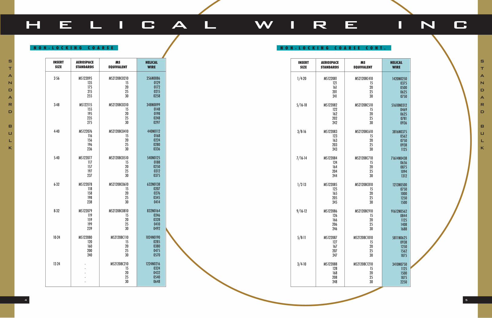
N O N - L O C K I N G C O A R S E C O N T . N O N - L O C K I N G C O A R S E
STANDARD
BULK
STANDARD
BULK
INSERT AEROSPACE MS HELICALSIZE STANDARDS EQUIVALENT WIRE
MS122081121161201241
MS122082122162202242
MS122083123163203243
MS122084124164204244
MS122085125165205245
MS122086126166206246
MS122087127167207247
MS122088128168208248
1/4-20
5/16-18
3/8-16
7/16-14
1/2-13
9/16-12
5/8-11
3/4-10
MS21208C41015202530
MS21208C51015202530
MS21208C61015202530
MS21208C71015202530
MS21208C81015202530
MS21208C91015202530
MS21208C101015202530
MS21208C121015202530
1420N02500375050006250750
51618N03120469062507810936
3816N03750562075009381125
71614N04380656087510941312
1213N05000750100012501500
91612N05620844112514081688
5811N06250938125015621875
3410N07501125150018752250
MS122095135175215255
MS122115155195235275
MS122076116156196236
MS122077117157197237
MS122078118158198238
MS122079119159199239
MS122080120160200240
-----
2-56
3-48
4-40
5-40
6-32
8-32
10-24
12-24
MS21208C021015202530
MS21208C031015202530
MS21208C041015202530
MS21208C051015202530
MS21208C061015202530
MS21208C081015202530
MS21208C11015202530
MS21208C21015202530
256N00860129017202150258
348N00990148019802480297
440N01120168022402800336
540N01250188025003120375
632N01380207027603450414
832N01640246032804100492
1024N01900285038004750570
1224N02160324043205400648
INSERT AEROSPACE MS HELICALSIZE STANDARDS EQUIVALENT WIRE
7
H E L I C A L W I R E I N C
6
N O N - L O C K I N G F I N E
When ordering Inconel per AS7246 add ‘X‘ at the end of the part number and before the plating letter. To specify Phosphor Bronze per AMS 7247
material add ‘B‘ after the part number and before the plating letter and for Nitronic 60 per AMS 5848B add “N”.
To order Dry Film Lube per AS5272 add an ‘L‘ at the end of the number. ‘W‘ appears after the ‘N‘ in the competitor’s part number. Example:
c/r1185-24CNW1500, 1126N1500L. To request Cad Plate per QQ-P-416 Rev. F add an ‘P‘ at the end of the number. ‘Y‘ appears after the ‘N‘ in the
competitor’s part number. Example: 1185-24CNY1500, 1126N1500P. For Primer Free per Xylan (R) 5251/840 Black add an ‘H‘ at the end of the number.
‘PF‘ appears after the ‘N‘ in the competitor’s part number. Example: 1185-24CNPF1500, 1126N1500H. For Silver Plate per AMS 2411 or QQ-S-365 add
‘V‘ at the end of the part number. Example: 1185-24CNV1500, 1126N1500V.
To request left hand thread add ‘LH‘ at the end of the part number and before plating letter.
N O N - L O C K I N G C O A R S E C O N T .
STANDARD
BULK
STANDARD
BULK
INSERT AEROSPACE MS HELICALSIZE STANDARDS EQUIVALENT WIRE
MS124670710750790830
MS124671711751791831
MS124653693733773813
MS124654694734774814
MS124655695735775815
MS124656696736776816
MS124657697737777817
MS124658698738778818
3-56
4-48
6-40
8-36
10-32
1/4-28
5/16-24
3/8-24
MS21208F031015202530
MS21208F041015202530
MS21208F061015202530
MS21208F081015202530
MS21208F11015202530
MS21208F41015202530
MS21208F51015202530
MS21208F61015202530
356N00990148019802480297
448N01120168022402800336
640N01380207027603450414
836N01640246032804100492
1032N01900285038004750570
1428N02500375050006250750
51624N03120469062507810938
3824N03750562075009381125
MS122089129169209249
MS122090130170210250
MS122091131171211251
MS122092132172212252
MS122093133173213253
MS122094134174214254
7/8-9
1-8
1 1/8-7
1 1/4-7
1 3/8-6
1 1/2-6
MS21208C141015202530
MS21208C161015202530
MS21208C181015202530
MS21208C201015202530
MS21208C221015202530
MS21208C241015202530
INSERT AEROSPACE MS HELICALSIZE STANDARDS EQUIVALENT WIRE
789N08751312175021882625
18N10001500200025003000
1187N11251688225028123375
1147N12501875250031253750
1386N13752052275034384125
1126N15002250300037504500
9
H E L I C A L W I R E I N C
8
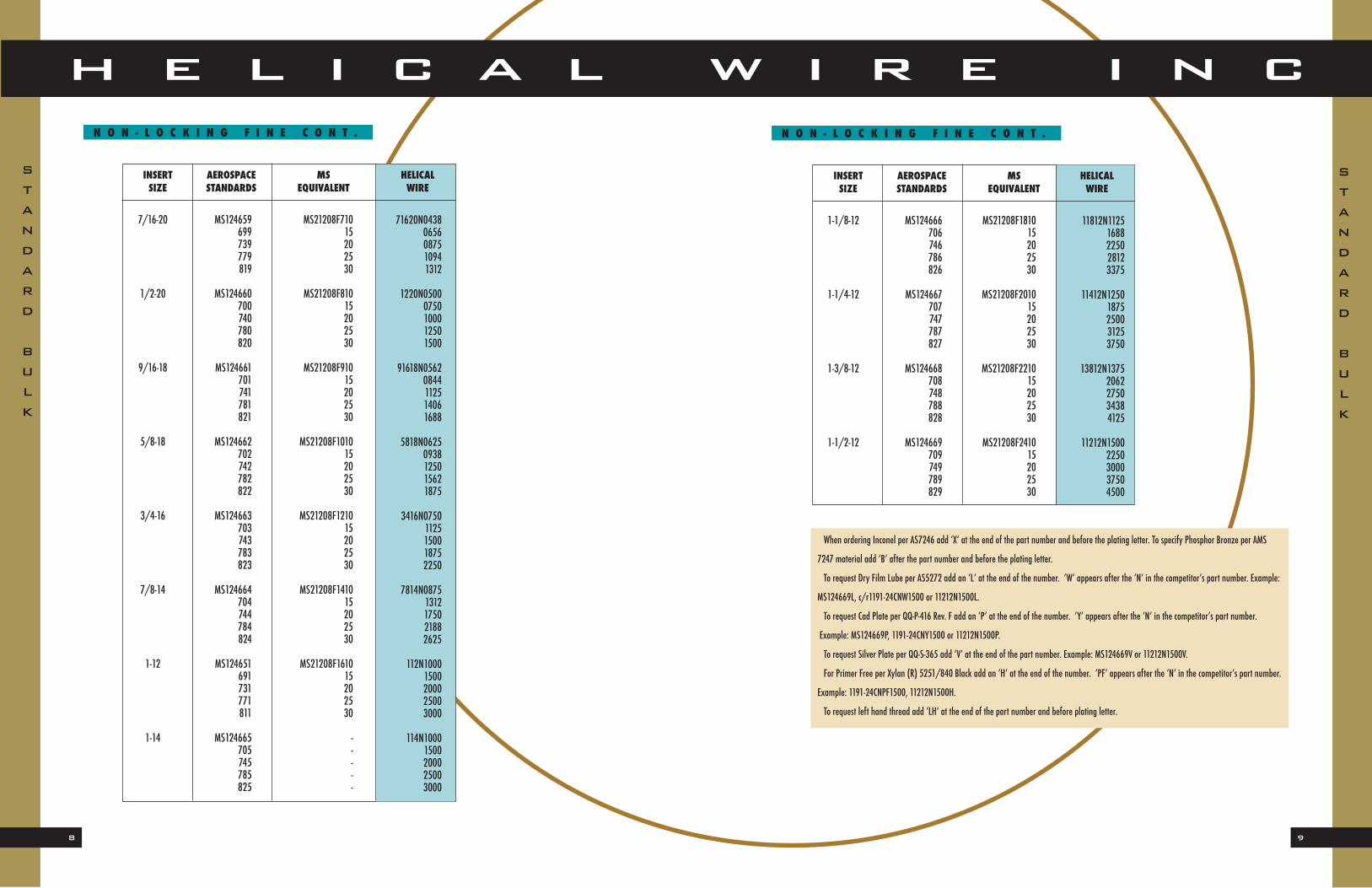
INSERT AEROSPACE MS HELICALSIZE STANDARDS EQUIVALENT WIRE
MS124666706746786826
MS124667707747787827
MS124668708748788828
MS124669709749789829
1-1/8-12
1-1/4-12
1-3/8-12
1-1/2-12
MS21208F181015202530
MS21208F201015202530
MS21208F221015202530
MS21208F241015202530
11812N11251688225028123375
11412N12501875250031253750
13812N13752062275034384125
11212N15002250300037504500
When ordering Inconel per AS7246 add ‘X‘ at the end of the part number and before the plating letter. To specify Phosphor Bronze per AMS
7247 material add ‘B‘ after the part number and before the plating letter.
To request Dry Film Lube per AS5272 add an ‘L‘ at the end of the number. ‘W‘ appears after the ‘N‘ in the competitor’s part number. Example:
MS124669L, c/r1191-24CNW1500 or 11212N1500L.
To request Cad Plate per QQ-P-416 Rev. F add an ‘P‘ at the end of the number. ‘Y‘ appears after the ‘N‘ in the competitor’s part number.
Example: MS124669P, 1191-24CNY1500 or 11212N1500P.
To request Silver Plate per QQ-S-365 add ‘V‘ at the end of the part number. Example: MS124669V or 11212N1500V.
For Primer Free per Xylan (R) 5251/840 Black add an ‘H‘ at the end of the number. ‘PF‘ appears after the ‘N‘ in the competitor’s part number.
Example: 1191-24CNPF1500, 11212N1500H.
To request left hand thread add ‘LH‘ at the end of the part number and before plating letter.
N O N - L O C K I N G F I N E C O N T . N O N - L O C K I N G F I N E C O N T .
STANDARD
BULK
STANDARD
BULK
INSERT AEROSPACE MS HELICALSIZE STANDARDS EQUIVALENT WIRE
MS124659699739779819
MS124660700740780820
MS124661701741781821
MS124662702742782822
MS124663703743783823
MS124664704744784824
MS124651691731771811
MS124665705745785825
7/16-20
1/2-20
9/16-18
5/8-18
3/4-16
7/8-14
1-12
1-14
MS21208F71015202530
MS21208F81015202530
MS21208F91015202530
MS21208F101015202530
MS21208F121015202530
MS21208F141015202530
MS21208F161015202530
-----
71620N04380656087510941312
1220N05000750100012501500
91618N05620844112514061688
5818N06250938125015621875
3416N07501125150018752250
7814N08751312175021882625
112N10001500200025003000
114N10001500200025003000
11
H E L I C A L W I R E I N C
10
When ordering Inconel per AS7246 add ‘X‘ at the end of the part
number and before the plating letter. To specify Phosphor Bronze per
AMS 7247 material add ‘B‘ after the part number and before the
plating letter.
To request Dry Film Lube per AS5272 add an ‘L‘ at the end of the
number. ‘W‘ appears after the ‘N‘ in the competitor’s part number.
Example: MS21209C1410L, c/r3585-14CNW0875 or 789L0875L.
To request Cad Plate per QQ-P-416 Rev. F add an ‘P‘ at the end of
the number. ‘Y‘ appears after the ‘N‘ in the competitor’s part
number. Example: MS21209C1410P, c/r3585-14CNY0875 or
789L0875P.
To request Silver Plate per QQ-S-365 add ‘V‘ at the end of the part
number. Example: MS21209C1410V or 789L0875V.
For Primer Free per Xylan (R) 5251/840 Black add an ‘H‘ at the
end of the number. ‘PF‘ appears after the ‘N‘ in the competitor’s
part number. Example: 789L0875H/3585-24CNPF1500.
To request left hand thread add ‘LH‘ at the end of the part number
and before plating letter.
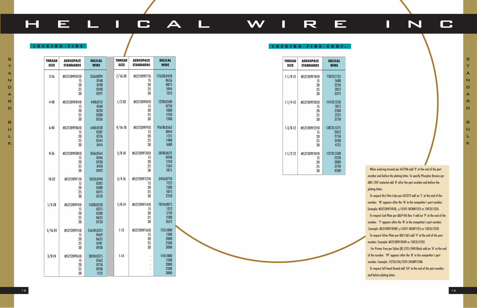
L O C K I N G C O A R S E C O N T .
2-56
3-48
4-40
5-40
6-32
8-32
10-24
12-24
MS21209C021015202530
MS21209C031015202530
MS21209C041015202530
MS21209C051015202530
MS21209C061015202530
MS21209C081015202530
MS21209C11015202530
MS21209C21015202530
256L00860129017202150258
348L00990148019802480297
440L01120168022402800336
540L01250188025003120375
632L01380207027603450414
832L01640246032804100492
1024L01900285038004750570
1224L02160324043205400648
L O C K I N G C O A R S E
THREAD AEROSPACE HELICALSIZE STANDARDS WIRE
STANDARD
BULK
STANDARD
BULK
7/8-9
1-8
1 1/8-7
1 1/4-7
1 3/8-6
1 1/2-6
MS21209C141015202530
MS21209C161015202530
MS21209C181015202530
MS21209C201015202530
MS21209C221015202530
MS21209C241015202530
789L08751312175021882625
18L10001500200025003000
1187L11251688225028123375
1147L12501875250031253750
1386L13752052275034384125
1126L15002250300037504500
THREAD AEROSPACE HELICALSIZE STANDARDS WIRE
THREAD AEROSPACE HELICALSIZE STANDARDS WIRE
1/4-20
5/16-18
3/8-16
7/16-14
1/2-13
9/16-12
5/8-11
3/4-10
MS21209C41015202530
MS21209C51015202530
MS21209C61015202530
MS21209C71015202530
MS21209C81015202530
MS21209C91015202530
MS21209C101015202530
MS21209C121015202530
1420L02500375050006250750
51618L03120469062507810938
3816L03750562075009381125
71614L04380656087510941312
1213L05000750100012501500
91612L05620844112514081688
5811L06250938125015621875
3410L07501125150018752250
13
H E L I C A L W I R E I N C
12
THREAD AEROSPACE HELICALSIZE STANDARDS WIRE
1-1/8-12
1-1/4-12
1-3/8-12
1-1/2-12
MS21209F181015202530
MS21209F201015202530
MS21209F221015202530
MS21209F241015202530
11812L11251688225028123375
11412L12501875250031253750
13812L13752052275034384125
11212L15002250300037504500 When ordering Inconel per AS7246 add ‘X‘ at the end of the part
number and before the plating letter. To specify Phosphor Bronze per
AMS 7247 material add ‘B‘ after the part number and before the
plating letter.
To request Dry Film Lube per AS5272 add an ‘L‘ at the end of the
number. ‘W‘ appears after the ‘N‘ in the competitor’s part number.
Example: MS21209F1810L, c/r3591-18CNW1125 or 11812L1125L.
To request Cad Plate per QQ-P-416 Rev. F add an ‘P‘ at the end of the
number. ‘Y‘ appears after the ‘N‘ in the competitor’s part number.
Example: MS21209F1810P, c/r3591-18CNY1125 or 11812L1125P.
To request Silver Plate per QQ-S-365 add ‘V‘ at the end of the part
number. Example: MS21209F1810V or 11812L1125V.
For Primer Free per Xylan (R) 5251/840 Black add an ‘H‘ at the end
of the number. ‘PF‘ appears after the ‘N‘ in the competitor’s part
number. Example: 11212L15H/3591-24CNPF1500.
To request left hand thread add ‘LH‘ at the end of the part number
and before plating letter.
L O C K I N G F I N E C O N T .L O C K I N G F I N E
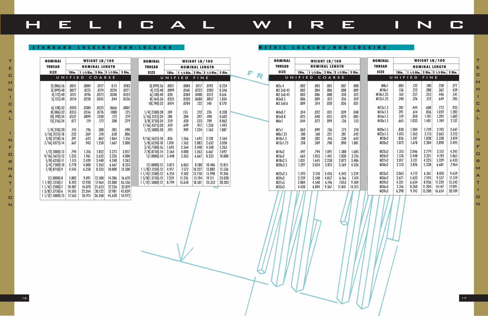
U N I F I E D F I N E1 1/2 Dia.1Dia. 2 1/2 Dia.2 Dia. Max.Min.
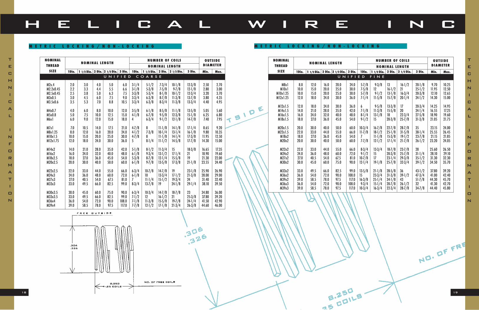
M E T R I C L O C K I N G / N O N - L O C K I N G
3 Dia. 1 1/2 Dia.1Dia. 2 1/2 Dia.2 Dia. 3 Dia.
TECHNICAL
INFORMATION
M2.0x.40N2.03.04.05.06.0
M2.2x.45N2.23.34.45.56.6
M2.5x.45N2.53.85.06.37.5
M3x.5N3.04.56.07.59.0
M3.5x.6N3.55.37.08.810.5
M4x.7N4.06.08.010.012.0
M5x.8N5.07.510.012.515.0
M6x1.0N6.09.012.015.018.0
21
H E L I C A L W I R E I N C
20
N O N - L O C K I N G M E T R I C C O N T .
THREAD AEROSPACE HELICALSIZE STANDARDS WIRE
M2 x.40N
M2.2 x.45N
M2.5 x.45N
M3 x0.5N
M3.5 x0.6N
M4 x0.7N
M5 x0.8N
M6 x1.0N
MA3279-140190240290340
MA3279-100150200250300
MA3279-101151201251301
MA3279-102152202252302
MA3279-103153203253303
MA3279-104154204254304
MA3279-105155205255305
MA3279-106156206256306
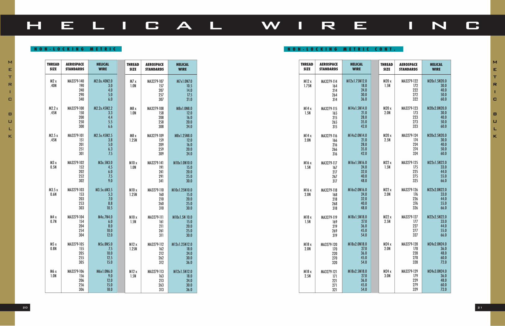
N O N - L O C K I N G M E T R I C
METRIC
BULK
METRIC
BULK
M7x1.0N7.010.514.017.521.0
M8x1.0N8.012.016.020.024.0
M8x1.25N8.012.016.020.024.0
M10x1.0N10.015.020.025.030.0
M10x1.25N10.015.020.025.030.0
M10x1.5N 10.015.020.025.030.0
M12x1.25N12.018.024.030.036.0
M12x1.5N12.018.024.030.036.0
THREAD AEROSPACE HELICALSIZE STANDARDS WIRE
M7 x1.0N
M8 x1.0N
M8 x1.25N
M10 x1.0N
M10 x1.25N
M10 x1.5N
M12 x1.25N
M12 x1.5N
MA3279-107157207257307
MA3279-108158208258308
MA3279-109159209259309
MA3279-141191241291341
MA3279-110160210260310
MA3279-111161211261311
MA3279-112162212262312
MA3279-113163213263313
THREAD AEROSPACE HELICALSIZE STANDARDS WIRE
THREAD AEROSPACE HELICALSIZE STANDARDS WIRE
M12 x1.75N
M14 x1.5N
M14 x2.0N
M16 x1.5N
M16 x2.0N
M18 x1.5N
M18 x2.0N
M18 x2.5N
MA3279-114164214264314
MA3279-115165215265315
MA3279-116166216266316
MA3279-117167217267317
MA3279-118168218268318
MA3279-119169219269319
MA3279-120170220270320
MA3279-121171221271321
M12x1.75N12.018.024.030.036.0
M14x1.5N14.021.028.035.042.0
M14x2.0N14.021.028.035.042.0
M16x1.5N16.024.032.040.048.0
M16x2.0N16.024.032.040.048.0
M18x1.5N18.027.036.045.054.0
M18x2.0N18.027.036.045.054.0
M18x2.5N18.027.036.045.054.0
M20 x1.5N
M20 x2.0N
M20 x2.5N
M22 x1.5N
M22 x2.0N
M22 x2.5N
M24 x2.0N
M24 x3.0N
MA3279-122172222272322
MA3279-123173223273323
MA3279-124174224274324
MA3279-125175225275325
MA3279-126176226276326
MA3279-127177227277327
MA3279-128178228278328
MA3279-129179229279329
M20x1.5N20.030.040.050.060.0
M20x2.0N20.030.040.050.060.0
M20x2.5N20.030.040.050.060.0
M22x1.5N22.033.044.055.066.0
M22x2.0N22.033.044.055.066.0
M22x2.5N22.033.044.055.066.0
M24x2.0N24.036.048.060.072.0
M24x3.0N24.036.048.060.072.0
23
H E L I C A L W I R E I N C
22
L O C K I N G M E T R I C
For Dry Film Lube per AS5272 add ‘L‘ at the end of the number. ‘W‘ appearsafter the ‘N‘ in the competitor’s part number. Example: MA3280-131, 1084-27CNW-27.0 or M27x3.0N27.0L. For Cad Plate per Q Q-P-416“F” add ‘P‘ at the end of the number. ‘Y‘ appears
after the ‘N‘ in the competitor’s part number. Example: MA3281-131, 1084-27CNY-27.0 or M27x3.0N27.0P. For Silver Plate per QQ-S-365 add ‘V‘ at the end of the part number. Example:
1084-27CNV-27.0 or M27x3.0N27.0V.For Primer Free per Xylan (R) 5251/840 Black add an ‘H‘ at the end of the
number. ‘PF‘ appears after the ‘N‘ in the competitor’s part number. Example:1084-27CNPF-27.0 or M27x3.0N27.0H.For left hand thread add ‘LH‘ at the end of the part number and before plating
letter. See page 19 for letter designation for Inconel and Phosphor Bronze material.
N O N - L O C K I N G M E T R I C C O N T .
METRIC
BULK
METRIC
BULK
THREAD AEROSPACE HELICALSIZE STANDARDS WIRE
THREAD AEROSPACE HELICALSIZE STANDARDS WIRE
M27 x2.0N
M27 x3.0N
M30 x2.0N
M30 x3.0N
M30 x3.5N
M33 x2.0N
M33 x3.0N
M33 x3.5N
MA3279-130180230280330
MA3279-131181231281331
MA3279-132182232282332
MA3279-133183233283333
-----
MA3279-134184234284334
MA3279-135185235285335
-----
M27x2.0N27.040.554.067.581.0
M27x3.0N27.040.554.067.581.0
M30x2.0N30.045.060.075.090.0
M30x3.0N30.045.060.075.090.0
M30x3.5N30.045.060.075.090.0
M33x2.0N33.049.566.082.599.0
M33x3.0N33.049.566.082.599.0
M33x3.5N33.049.566.082.599.0
M36 x2.0N
M36 x3.0N
M36 x4.0N
M39 x2.0N
M39 x3.0N
M39 x4.0N
MA3279-136186236286336
MA3279-137187237287337
-----
MA3279-138188238288338
MA3279-139189239289339
-----
M36x2.0N36.054.072.090.0108.0
M36x3.0N36.054.072.090.0108.0
M36x4.0N36.054.072.090.0108.0
M39x2.0N39.058.578.097.5117.0
M39x3.0N39.058.578.097.5117.0
M39x4.0N39.058.578.097.5117.0
THREAD AEROSPACE HELICALSIZE STANDARDS WIRE
THREAD AEROSPACE HELICALSIZE STANDARDS WIRE
M2 x.40L
M2.2 x.45L
M2.5 x.45L
M3 x0.5L
M3.5 x0.6L
M4 x0.7L
M5 x0.8L
M6 x1.0L
MA3329-190240290340
MA3329-100150200250300
MA3329-101151201251301
MA3329-102152202252302
MA3329-103153203253303
MA3329-104154204254304
MA3329-105155205255305
MA3329-106156206256306
M2.0x.40L3.04.05.06.0
M2.2x.45L2.23.34.45.56.6
M2.5x.45L2.53.85.06.37.5
M3x.5L3.04.56.07.59.0
M3.5x.6L3.55.37.08.810.5
M4x.7L4.06.08.010.012.0
M5x.8L5.07.510.012.515.0
M6x1.0L6.09.012.015.018.0
M7 x1.0L
M8 x1.0L
M8 x1.25L
M10 x1.0L
M10 x1.25L
M10 x1.5L
M12 x1.25L
M12 x1.5L
M7x1.0L7.010.514.017.521.0
M8x1.0L8.012.016.020.024.0
M8x1.25L8.012.016.020.024.0
M10x1.0L10.015.020.025.030.0
M10x1.25L10.015.020.025.030.0
M10x1.5L10.015.020.025.030.0
M12x1.25L12.018.024.030.036.0
M12x1.5L12.018.024.030.036.0
MA3329-107157207257307
MA3329-108158208258308
MA3329-109159209259309
MA3329-141191241291341
MA3329-110160210260310
MA3329-111161211261311
MA3329-112162212262312
MA3329-113163213263313
THREAD AEROSPACE HELICALSIZE STANDARDS WIRE
THREAD AEROSPACE HELICALSIZE STANDARDS WIRE
25
H E L I C A L W I R E I N C
24
M27 x2.0L
M27 x3.0L
M30 x2.0L
M30 x3.5L
M33 x2.0L
M33 x3.0L
M33 x3.5L
M36 x2.0L
MA3329-130180230280330
MA3329-131181231281331
MA3329-132182232282332
-----
MA3329-134184234284334
MA3329-135185235285335
-----
MA3329-136186236286336
M27x2.0L27.040.554.067.581.0
M27x3.0L27.040.554.067.581.0
M30x2.0L30.045.060.075.090.0
M30x3.5L30.045.060.075.090.0
M33x2.0L33.049.566.082.599.0
M33x3.0L33.049.566.082.599.0
M33x3.5L33.049.566.082.599.0
M36x2.0L36.054.072.090.0108.0
M36 x3.0L
M36 x4.0L
M39 x2.0L
M39 x3.0L
M39 x4.0L
MA3329-137187237287337
-----
MA3329-138188238288338
MA3329-139189239289339
-----
M36x3.0L36.054.072.090.0108.0
M36x4.0L36.054.072.090.0108.0
M39x2.0L39.0 58.578.097.5117.0
M39x3.0L39.058.578.097.5117.0
M39x4.0L39.058.578.097.5117.0
L O C K I N G M E T R I C C O N T .
When ordering Inconel per AS7246 add ‘X’ at the end of the part numberand before the plating letter. To specify Phosphor Bronze per AMS 7247 material add ‘B’ after the part number and before the plating letter, and forNitronic 60 per AMS 5848B add “N”. For Dry Film Lube per AS5272 add ‘L‘ at the end of the number. ‘W‘
appears after the ‘N‘ in the competitor’s part number. Example: MA3330-131,4184-27CNW-27.0 or M27x3.0L27.0L. For Cad Plate per Q Q-P-416 Rev. F add‘P‘ at the end of the number. ‘Y‘
appears after the ‘N‘ in the competitor’s part number. Example: MA3331-131,4184-27CNY-27.0 or M27x3.0L27.0P. For Silver Plate per QQ-S-365 add ‘V‘ at the end of the part number.
Example: 4184-27CNV-27.0 or M27x3.0L27.0V.For Primer Free per Xylan (R) 5251/840 Black add an ‘H‘ at the end of the
number. Example: MA3329-131H, 4184-27CNPF-27.0 or M27x3.0L27.0H.
The concept behind screw thread inserts is simple. Drill the hole, tap the drilled hole, install the insert. It is a relatively simple process, but the correct drilling of the initial hole is critical. If the hole is drilled correctly then the hole will be theproper diameter to accommodate the tap. The tap will create threads in the parent material that will be the proper diameter to correctly install the insert. When the insert is correctly installed, the bolt or screw will seat perfectly into thetapped hole. The process can be quite difficult if any step is done incorrectly. Reference MS33537.Helical Wire Inc. wants to be sure that anyone who uses our inserts can avoid any potential problems. We have suggested
sizes for drills to achieve the correct diameter for the particular size of insert that you are using. The following tables listthese sizes, and all of these drills are carried in our stock.
1-1/8-7 1-11/64 (1.1719) 1-11/64 (1.1719)1-1/4-7 1-19/64 (1.2969) 1-19/64 (1.2969)1-3/8-6 1-27/64 (1.4219) 1-27/64 (1.4219)1-1/2-6 1-35/64 (1.5469) 1-35/64 (1.5469) Alternate drill sizes are suggested in many instances for magnesium, steel and plas-
tics to provide for maximum tap wear and life.
U N I F I E D C O A R S E
S T A N D A R D D R I L L S
DRILLING
DRILLING
29
H E L I C A L W I R E I N C
28
Helical Wire Inserts are commonly characterized as ”screw thread” inserts. In order to fasten two mechanical componentstogether using conventional hardware fasteners, you must have something for those fasteners to screw into. But even be-fore a screw thread insert can accommodate any hardware fastener, the insert has to be installed into the parent material.The preparation of the parent material involves the drilling of a hole into the component. Whether it is a through-hole or
a blind-hole, the correct sized drill must be used. Once the hole is correctly prepared it must be tapped to create the threadsthat will allow the installation of the insert. The tap that is used to do this should always be an STI type tap. The STI designation is specifically manufactured for the use with screw thread inserts.The tapping of the prepared hole is just as important as using the correct size of inserts in the overall fastening
application. If an application calls for the installation of a 10-32 sized insert, a 10-32 STI tap must be used. Depending onthe fit requirements in the installation of the inserts a particular “H” limit may be specified for the tap. A particular size oftap will have a pre-determined outside diameter. The “H” limit will raise that outside diameter limit by .0005. For examplea 10-32 STI tap with an “H-2” classification will be .0005 smaller on its outside diameter than the same sized tap with an“H-3”classification. These “H” limits allow the installer to get the class fit they desire.There are different tapping needs in various kinds of installations. Depending on the type of hole in the application, there
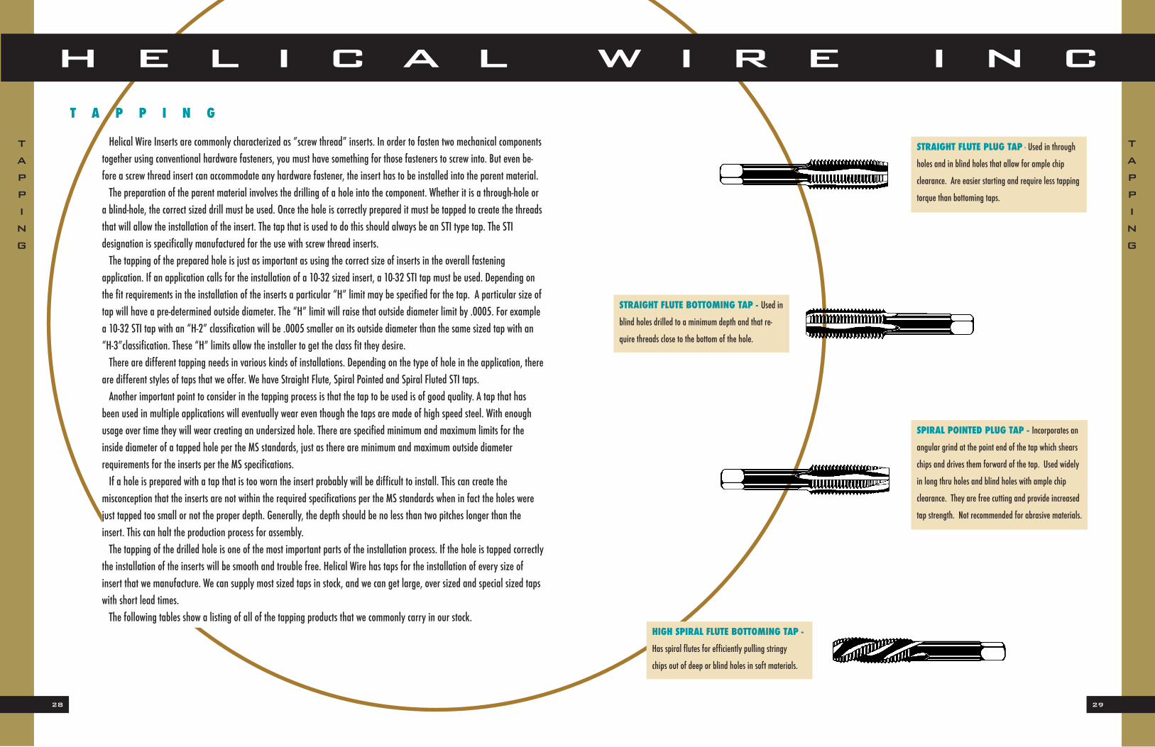
are different styles of taps that we offer. We have Straight Flute, Spiral Pointed and Spiral Fluted STI taps.Another important point to consider in the tapping process is that the tap to be used is of good quality. A tap that has
been used in multiple applications will eventually wear even though the taps are made of high speed steel. With enoughusage over time they will wear creating an undersized hole. There are specified minimum and maximum limits for theinside diameter of a tapped hole per the MS standards, just as there are minimum and maximum outside diameter requirements for the inserts per the MS specifications.If a hole is prepared with a tap that is too worn the insert probably will be difficult to install. This can create the
misconception that the inserts are not within the required specifications per the MS standards when in fact the holes werejust tapped too small or not the proper depth. Generally, the depth should be no less than two pitches longer than theinsert. This can halt the production process for assembly. The tapping of the drilled hole is one of the most important parts of the installation process. If the hole is tapped correctly
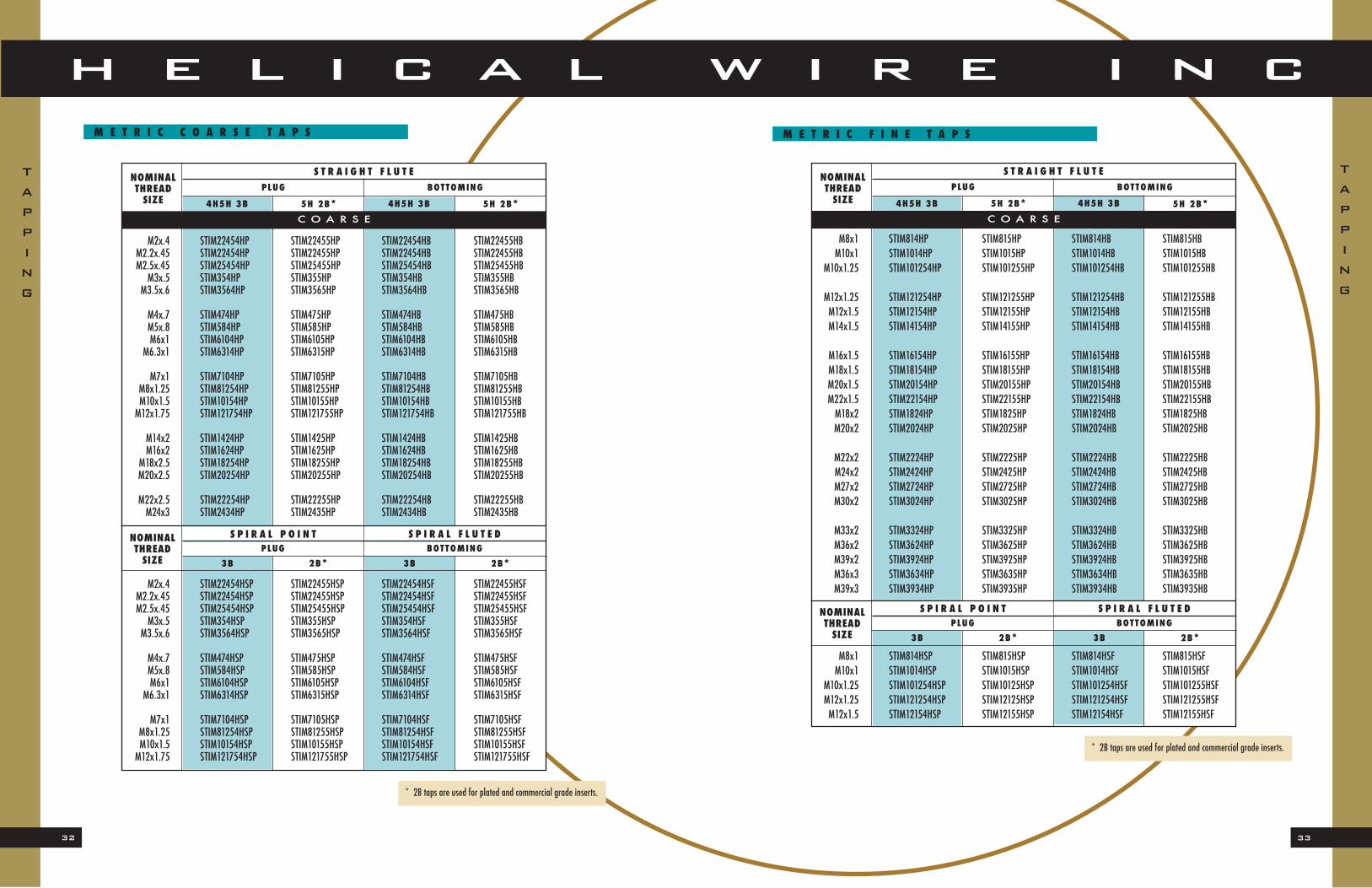
the installation of the inserts will be smooth and trouble free. Helical Wire has taps for the installation of every size of insert that we manufacture. We can supply most sized taps in stock, and we can get large, over sized and special sized tapswith short lead times.The following tables show a listing of all of the tapping products that we commonly carry in our stock.
T A P P I N G
TAPPING
TAPPING
STRAIGHT FLUTE PLUG TAP - Used in through
holes and in blind holes that allow for ample chip
clearance. Are easier starting and require less tapping
torque than bottoming taps.
STRAIGHT FLUTE BOTTOMING TAP - Used in
blind holes drilled to a minimum depth and that re-
quire threads close to the bottom of the hole.
HIGH SPIRAL FLUTE BOTTOMING TAP -
Has spiral flutes for efficiently pulling stringy
chips out of deep or blind holes in soft materials.
SPIRAL POINTED PLUG TAP - Incorporates an
angular grind at the point end of the tap which shears
chips and drives them forward of the tap. Used widely
in long thru holes and blind holes with ample chip
clearance. They are free cutting and provide increased
tap strength. Not recommended for abrasive materials.
* 2B taps are used for plated and commercial grade inserts.
* 2B taps are used for plated and commercial grade inserts.
S P I R A L P O I N TPLUG BOTTOMING
S P I R A L F L U T E DNOMINALTHREADSIZE
NOMINALTHREADSIZE
S T R A I G H T F L U T EPLUG
4H5H 3B
BOTTOMING
5H 2B* 4H5H 3B 5H 2B*C O A R S E
3B 2B* 3B 2B*
S P I R A L P O I N TPLUG BOTTOMING
S P I R A L F L U T E DNOMINALTHREADSIZE
NOMINALTHREADSIZE
35
H E L I C A L W I R E I N C
34
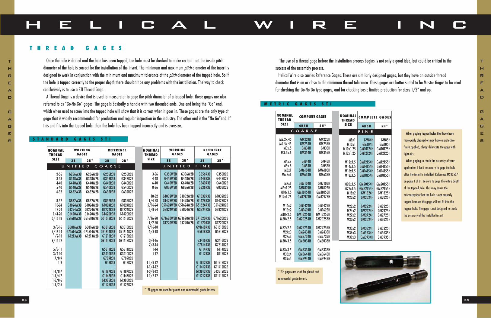
The use of a thread gage before the installation process begins is not only a good idea, but could be critical in the success of the assembly process.Helical Wire also carries Reference Gages. These are similarly designed gages, but they have an outside thread
diameter that is on or close to the minimum thread tolerance. These gages are better suited to be Master Gages to be usedfor checking the Go-No Go type gages, and for checking basic limited production for sizes 1/2” and up.
M E T R I C G A G E S S T I
T H R E A D G A G E S
Once the hole is drilled and the hole has been tapped, the hole must be checked to make certain that the inside pitch diameter of the hole is correct for the installation of the insert. The minimum and maximum pitch diameter of the insert isdesigned to work in conjunction with the minimum and maximum tolerance of the pitch diameter of the tapped hole. So ifthe hole is tapped correctly to the proper depth there shouldn’t be any problems with the installation. The way to check conclusively is to use a STI Thread Gage.A Thread Gage is a device that is used to measure or to gage the pitch diameter of a tapped hole. These gages are also
referred to as “Go-No Go” gages. The gage is basically a handle with two threaded ends. One end being the “Go” end,which when used to screw into the tapped hole will show that it is correct when it goes in. These gages are the only type ofgage that is widely recommended for production and regular inspection in the industry. The other end is the ”No Go”end. Ifthis end fits into the tapped hole, then the hole has been tapped incorrectly and is oversize.
NOMINALTHREADSIZE
WORKINGGAGES
REFERENCEGAGES
NOMINALTHREADSIZE
WORKINGGAGES
REFERENCEGAGES
S T A N D A R D G A G E S S T IWhen gaging tapped holes that have been
thoroughly cleaned or may have a protective
finish applied, always lubricate the gage with
light oils.
When gaging to check the accuracy of your
application it isn’t necessary to gage the hole
after the insert is installed. Reference MS33537
on page 1 of 9. Be sure to gage the entire depth
of the tapped hole. This may cause the
misconception that the hole is not properly
tapped because the gage will not fit into the
tapped hole. The gage is not designed to check
the accuracy of the installed insert.
THREAD
GAGES
THREAD
GAGES
* 2B gages are used for plated and commercial grade inserts.
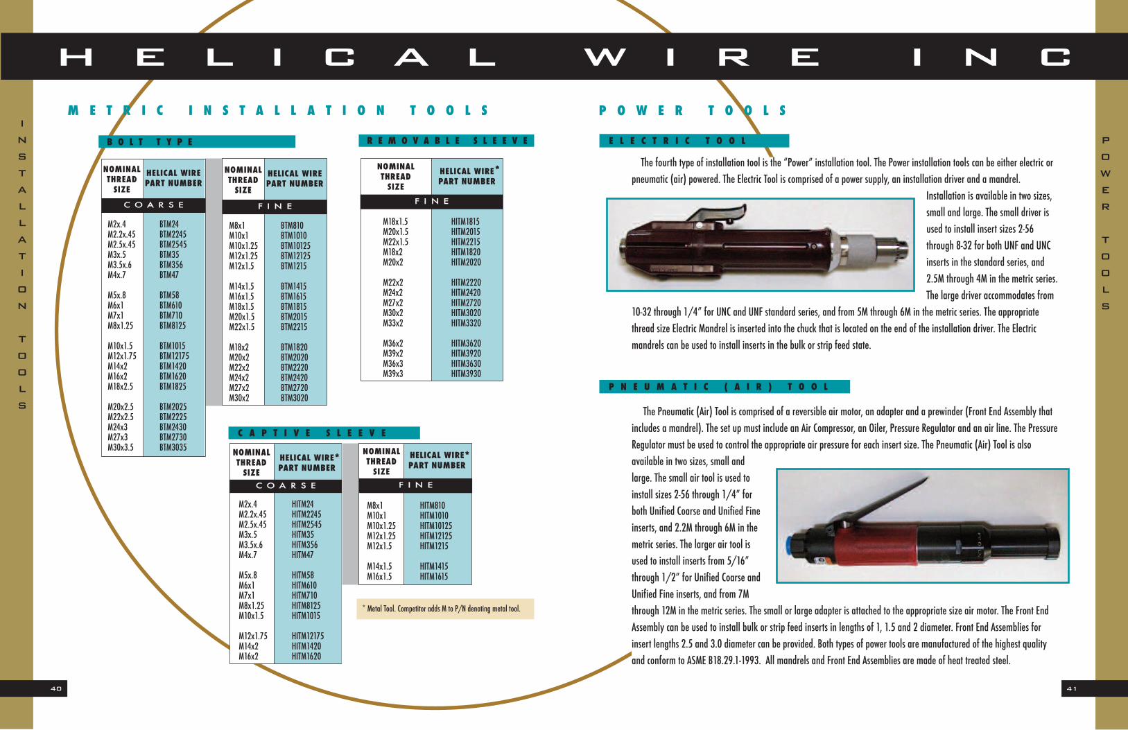
The first type of installation tool is what we refer to as the “Bolt Type” installation tool. This type is basically the same asa threaded bolt, with the exception of the recessed end of the threaded mandrel used to pick up the insert tang. This type isalso machined to be square at the other end to accommodate turning the tool with a conventional wrench for installation. This Bolt Type is usually used when installing a small number of inserts. It is the most cost effective and efficient way to
install a few inserts, and it is the type that we include in all of our installation kits. Some of the larger Bolt Type installationtools are machined with a hole drilled through the opposite end from the mandrel. This is done so that a steel pin can slideinto it for the purpose of leverage to rotate and install the larger inserts. All of the Bolt Type installation tools are made ofheat treated steel and are manufactured to conform to A-A-59158.
When the processes of drilling, tapping, and gauging have all been completed, the insert is ready to be installed. Nowthat the thread gauge has determined that the tapped hole is the right size and depth for the insert, the next step is to usethe right size and type of installation tool for the particular application being used.Installation tools are designed to make use of the “tang” mechanism that is on the last coil of every insert. Every
installation tool, regardless of type or size, will have a threaded shaft or mandrel piece that is machined to have an abruptend to the threads. This creates a recessed edge at the end of these threads that will allow the installation tool’s shaft to godown through the interior of the insert and pick up the tang of the insert against this recessed edge. As the installation
tool’s shaft is rotated it drives the insert downinto the tapped hole to the proper depth usingthe depth control.When the insert is being installed it experi-
ences what is called the insert retention principle. What this means is when the insert isin a free state before the installation process begins, it’s outside diameter will actually begreater than the inside diameter of the tappedhole.As the installation tool’s mandrel drives the
insert into the hole, the torque applied by thetool on the tang mechanism will cause the leadcoil of the insert to actually reduce in diameter.This reduction in diameter allows the insert to
be driven into the hole, even though the insert is technically larger in size. When the insert is seated in the tapped hole to the proper depth, the coils will experience an expansion and will actually spring back against the inside of the tapped hole. This allows for a tight fit that will permanently anchor the insert in place. The insert will automatically adjust itself both radially and axially to any expansionor contraction of the parent material.The installation of the insert always involves the same basic procedure. It will always use the tang mechnis to drive the
insert into the tapped hole, and will always experience the tang retention principle. However every installation is not always the same. Depending on the size of insert, type of insert and circumstances in the installation process there are different types of installation tools to be used .There are four types of installation tools that can be used to install Helical Wire inserts correctly and efficiently. They are
the Captive Sleeve, Removable Captive Sleeve, Bolt Type and Power Tools, both electric and pneumatic.
INSTALLATION
TOOLS
INSTALLATION
TOOLS
39
H E L I C A L W I R E I N C
38
The third type of installation tool is referred to as the “Removable Captive Sleeve” type. This type is a cross between theBolt type and the Captive Sleeve type. It has a shaft with a threaded mandrel end, and the other end has a perpendicularsteel pin or rod to turn it. This type also has a sleeve that is removable, and when removed, can be rear loaded with the insert. When the sleeve with the insert inside is slid back onto the tool it is ready to turn the handle and install the insert.The Removable Captive Sleeve tool operates on the same basic principle as the Captive Sleeve tool, but one is side loadedand one is rear loaded. The Removable Captive Sleeve accommo-dates the larger sized inserts thatwould otherwise be too big for theregular Captive Sleeve type. The Removable Captive Sleeve style isavailable in fine thread sizes thatpick up where the regular CaptiveSleeve tools leave off.
R E M O V A B L E S L E E V E
They are available in fine thread sizes 9/16
and up in the standard series. The metric
series are available for 12M and up.
The second type of installation tool is probably the most requested and the most used. This is the “Captive Sleeve” type.The Captive Sleeve installation tool works similarly to the Bolt Type, but the threaded shaft portion is covered by a steelcylinder sleeve. One end of the shaft has a threaded mandrel and on the other end has a hand crank to rotate the mandrel.
The sleeve has an insert sized slot in its side on the mandrel end.When the inside shaft is slid back within the chamber it allows the insert to enter into the cylinder. With the insert in the chamber, themandrel can be slid down to engage with the insert’s tang, and thehand crank will drive the insert into the hole. The tool is equippedwith a set screw to control depth of the installed insert.This type of tool allows for maximum control because it is done
manually with the hand crank, and the operator controls the amountof torque used to install the inserts. The Captive Sleeve tool is alsomade with a slotted end on the sleeve that is well suited for installingthe strip feed inserts. The slot accommodates the plastic tape as eachstrip fed insert is installed. All of these tools are made of heat
treated steel and conform to A-A-59158. They can be used for numerous installations. This Captive Sleeve or hand crankstyle of installation tool is available for sizes 2-56 through 1/2-13 UNC, and for sizes 3-56 through 1/2-20 UNF in the standard series. They are available in the metric series from 2.2M through 18M.
The fourth type of installation tool is the “Power” installation tool. The Power installation tools can be either electric orpneumatic (air) powered. The Electric Tool is comprised of a power supply, an installation driver and a mandrel.
Installation is available in two sizes,small and large. The small driver isused to install insert sizes 2-56through 8-32 for both UNF and UNCinserts in the standard series, and2.5M through 4M in the metric series.The large driver accommodates from
10-32 through 1/4” for UNC and UNF standard series, and from 5M through 6M in the metric series. The appropriatethread size Electric Mandrel is inserted into the chuck that is located on the end of the installation driver. The Electric mandrels can be used to install inserts in the bulk or strip feed state.
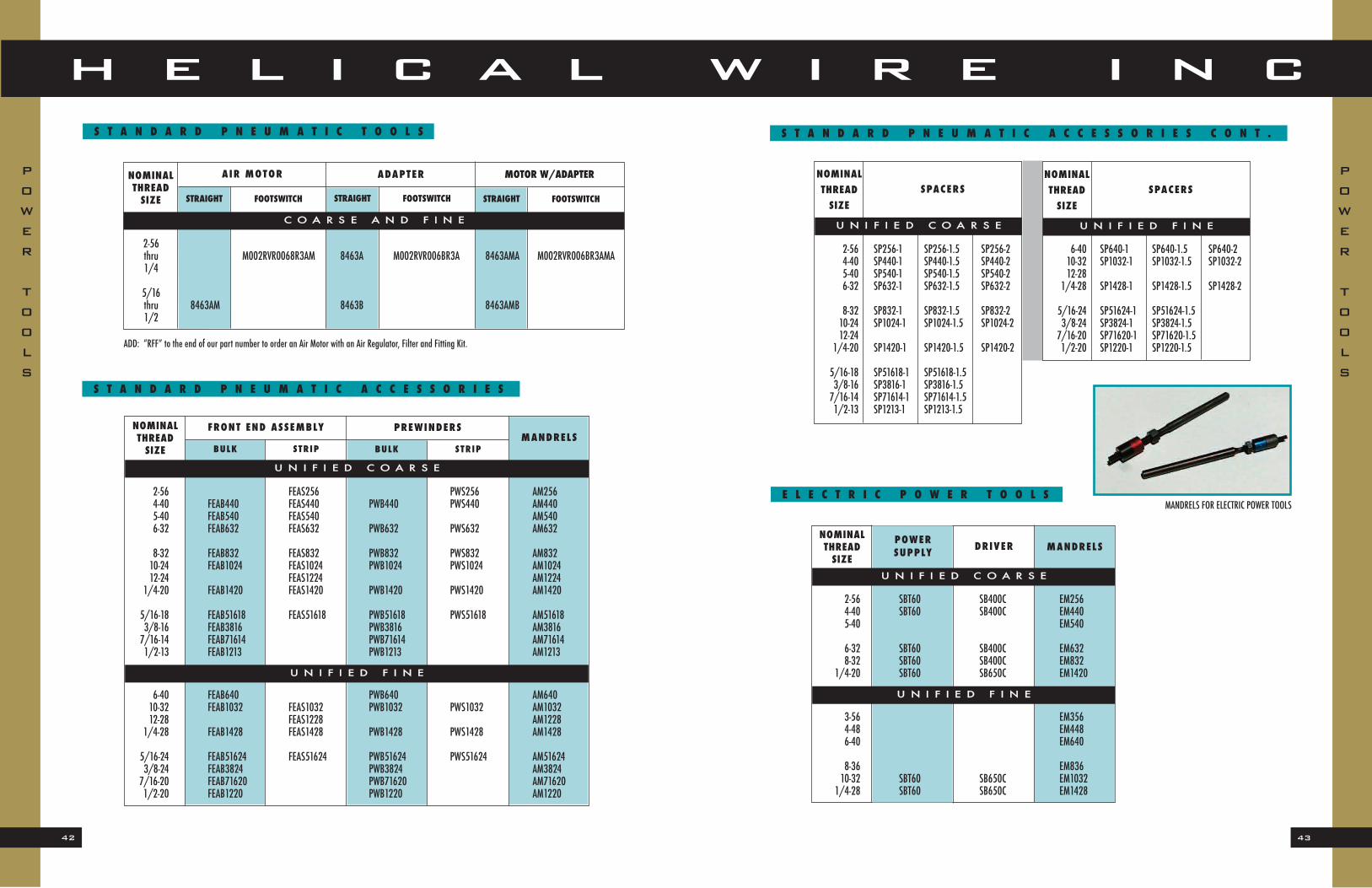
The Pneumatic (Air) Tool is comprised of a reversible air motor, an adapter and a prewinder (Front End Assembly thatincludes a mandrel). The set up must include an Air Compressor, an Oiler, Pressure Regulator and an air line. The PressureRegulator must be used to control the appropriate air pressure for each insert size. The Pneumatic (Air) Tool is alsoavailable in two sizes, small andlarge. The small air tool is used toinstall sizes 2-56 through 1/4” forboth Unified Coarse and Unified Fineinserts, and 2.2M through 6M in themetric series. The larger air tool isused to install inserts from 5/16”through 1/2” for Unified Coarse andUnified Fine inserts, and from 7Mthrough 12M in the metric series. The small or large adapter is attached to the appropriate size air motor. The Front EndAssembly can be used to install bulk or strip feed inserts in lengths of 1, 1.5 and 2 diameter. Front End Assemblies forinsert lengths 2.5 and 3.0 diameter can be provided. Both types of power tools are manufactured of the highest qualityand conform to ASME B18.29.1-1993. All mandrels and Front End Assemblies are made of heat treated steel.
When screw thread inserts are installed they are screwed into the tapped hole by the tang mechanism on the last coil ofthe insert. The installation tool rotates the insert as it goes down into the hole until it is installed to the proper depth. Atthis point the tool is removed, and the installation is done. However there is one more step that should be followed beforethe bolt is fastened into the hole. This would be the breaking off of the tang. Some applications do not require the tang tobe removed.The tang that drives the insert can be removed to eliminate any interference with the bolt. The removal of the tang
provides for greater variation in the depth location of the bolt, and may avoid the possibility of the bolt not seating to the proper depth.The tools that are used to remove or break off the tangs from the installed insert are called “Tang Break-Off Tools”.
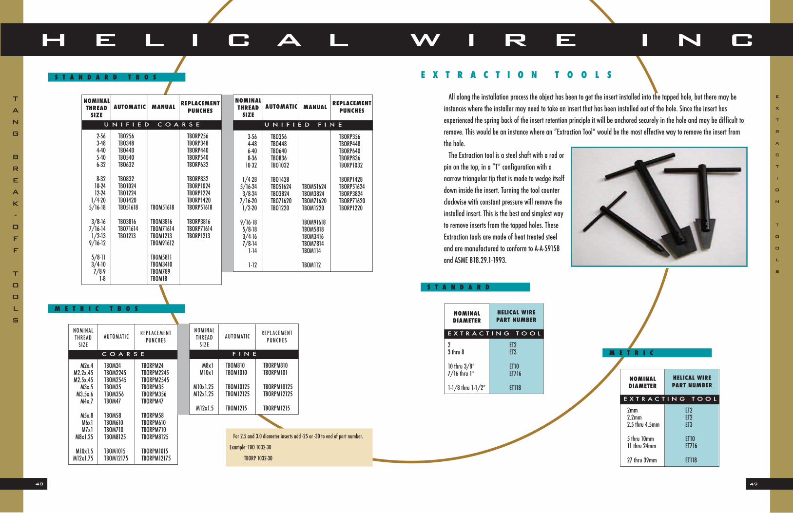
There are two types of Tang Break-Off tools that Helical Wire can provide, Automatic and Manual. The Automatic type has a spring loaded
sleeve that actuates a punch. When insertingthe tool into the hole where the insert has beeninstalled, the Automatic Tang Break-Off tool, orT.B.O., should be resting with the punch on topof the tang. When pressure is applied on thetool it will activate the spring loaded punch tostrike a uniform blow on the tang, which willbreak it off at the notched location. The Automatic style of T.B.O. is available for sizes 2-56 through 1/2” for both UNF and UNC inserts in the standard series, and can be usedfor sizes 2.2M through 12M in the metric series.
The Manual type of T.B.O. tool is similar to the Automatic tool, but the punch is loose in the insert. Be sure to use the proper size punch. When the tool is in place and the punch is mounted directly over the tang, the tool needs to be strucksharply by a hammer or mallet to break the tang off of the insert. The Manual type of T.B.O. tool is available for sizes9/16 through 1” in UNF and UNC for the standard series, and for 14M and up in the metric series.Both of these types of T.B.O. tools will do the job of removing the tangs from the installed inserts to allow for a hassle
free bolt installation.
T A N G B R E A K - O F F T O O L S
All T.B.O. tools are made of heat treated steel and conform to the MIL
Spec standard A-A-59158 and ASME B18.29.1-1993.
S T R I P F E E D
Helical Wire Inc. can supply our customers with screw thread inserts that are available in various materials and finisheson reels for multiple insert installing applications.We commonly refer to this as “Strip Feed”. The inserts are centered on a pre-determined length of plastic tape at equal
depths. The Strip Feed is available in increments of one hundred pieces, and usually prepared 500, 1000, 1500 or 2000pieces per reel depending on the size of the inserts.Once the parts are installed into the plastic tape they are wound onto a spool, or reel so that they can be unwound as
they are being installed. This Strip Feed style of inserts is the most effective way to utilize the inserts for assembly line typeoperations where many inserts are being installed in succession. This Strip Feed is also most effectively installed with thepower installation tools for rapid and accurate installation.Helical Wire also provides our customers,
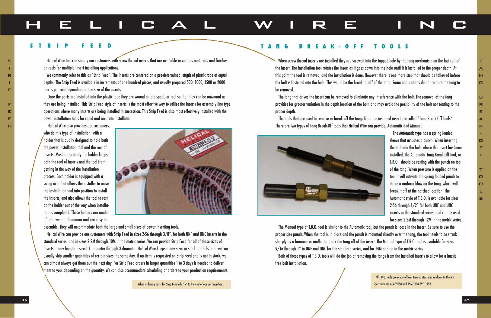
who do this type of installation, with aholder that is dually designed to hold boththe power installation tool and the reel ofinserts. Most importantly the holder keepsboth the reel of inserts and the tool from getting in the way of the installationprocess. Each holder is equipped with aswing arm that allows the installer to movethe installation tool into position to installthe inserts, and also allows the tool to reston the holder out of the way when installa-tion is completed. These holders are madeof light weight aluminum and are easy toassemble. They will accommodate both the large and small sizes of power inserting tools.Helical Wire can provide our customers with Strip Feed in sizes 2-56 through 3/8”, for both UNF and UNC inserts in the
standard series, and in sizes 2.2M through 10M in the metric series. We can provide Strip Feed for all of these sizes of inserts in any length desired: 1 diameter through 3 diameter. Helical Wire keeps many sizes in stock on reels, and we canusually ship smaller quantities of certain sizes the same day. If an item is requested on Strip Feed and is not in stock, wecan almost always get them out the next day. For Strip Feed orders in larger quantities 1 to 3 days is needed to deliverthem to you, depending on the quantity. We can also accommodate scheduling of orders to your production requirements.
When ordering parts for Strip Feed add “S” to the end of our part number.
TANG
BREAK-OFF
TOOLS
STRIP
FEED
49
H E L I C A L W I R E I N C
48
E X T R A C T I O N T O O L S
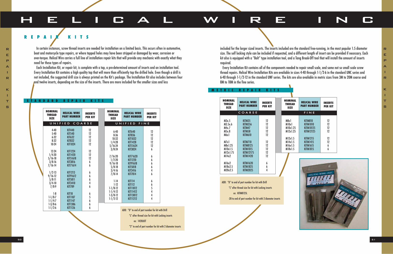
All along the installation process the object has been to get the insert installed into the tapped hole, but there may be instances where the installer may need to take an insert that has been installed out of the hole. Since the insert has experienced the spring back of the insert retention principle it will be anchored securely in the hole and may be difficult toremove. This would be an instance where an “Extraction Tool” would be the most effective way to remove the insert fromthe hole. The Extraction tool is a steel shaft with a rod or
pin on the top, in a “T” configuration with a narrow triangular tip that is made to wedge itselfdown inside the insert. Turning the tool counterclockwise with constant pressure will remove theinstalled insert. This is the best and simplest wayto remove inserts from the tapped holes. TheseExtraction tools are made of heat treated steeland are manufactured to conform to A-A-59158and ASME B18.29.1-1993.
For 2.5 and 3.0 diameter inserts add -25 or -30 to end of part number.
Example: TBO 1032-30
TBORP 1032-30
E
X
T
R
A
C
T
I
O
N
T
O
O
L
S
TANG
BREAK-OFF
TOOLS
NOMINALDIAMETER
E X T R A C T I N G T O O L
HELICAL WIREPART NUMBER
2mm ET22.2mm ET22.5 thru 4.5mm ET3
5 thru 10mm ET1011 thru 24mm ET716
27 thru 39mm ET118
51
H E L I C A L W I R E I N C
50
included for the larger sized inserts. The inserts included are the standard free-running, in the most popular 1.5 diametersize. The self locking style can be included if requested, and a different length of insert can be provided if necessary. Eachkit also is equipped with a “Bolt“ type installation tool, and a Tang Break-Off tool that will install the amount of insertsrequired.Every Installation Kit contains all of the components needed to repair small scale, and some not so small scale screw
thread repairs. Helical Wire Installation Kits are available in sizes 4-40 through 1-1/2-6 in the standard UNC series and 6-40 through 1-1/2-12 in the standard UNF series. The kits are also available in metric sizes from 3M to 20M coarse and8M to 18M in the fine series.
M E T R I C R E P A I R K I T S
ADD: “D” to end of part number for kit with Drill
“L” after thread size for kit with Locking inserts
ex: KITM8125L
-20 to end of part number for kit with 2 diameter inserts
R E P A I R K I T S
In certain instances, screw thread inserts are needed for installation on a limited basis. This occurs often in automotive,boat and motorcycle type repairs, or where tapped holes may have been stripped or damaged by wear, corrosion or over-torque. Helical Wire carries a full line of installation repair kits that will provide any mechanic with exactly what theyneed for these types of repairs. Each Installation Kit, or repair kit, is complete with a tap, a pre-determined amount of inserts and an installation tool.
Every Installation Kit contains a high quality tap that will more than efficiently tap the drilled hole. Even though a drill isnot included, the suggested drill size is always printed on the Kit’s package. The Installation Kit also includes between fourand twelve inserts, depending on the size of the inserts. There are more included for the smaller sizes and less
and technical information for smooth user operation. Military kits are available in a full range of sizes. The standard Inchseries is available from 2-56 through 1-1/2-6 in the Coarse Thread,(UNC) and from 3-56 through 1-1/4-12 in the Fine Se-ries,(UNF). They are also available in Metric sizes from M3x.5 through M18x1.5 with various wire sizes to choose from. Allkits are available with Drills and 2.0 diameter length inserts upon request. Each of our Military style kits provides an effi-cient and economical solution for mechanical problems in critical threaded applications.
REPAIR
KITS
REPAIR
KITS
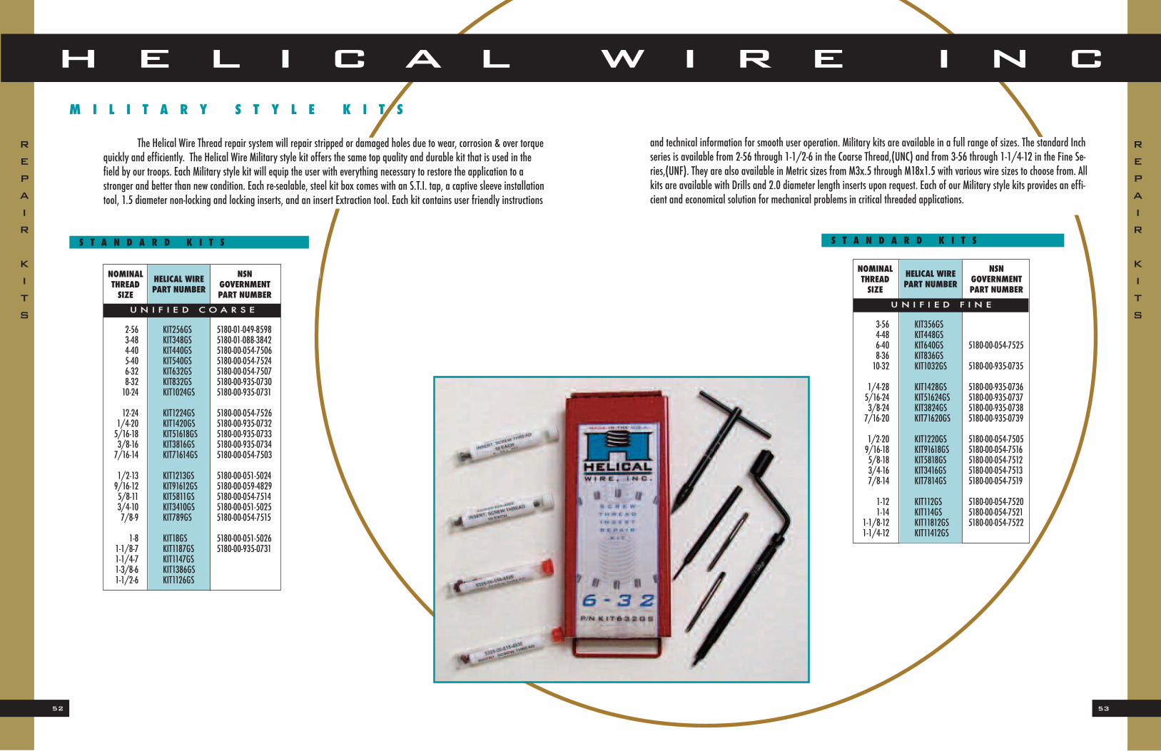
The Helical Wire Thread repair system will repair stripped or damaged holes due to wear, corrosion & over torquequickly and efficiently. The Helical Wire Military style kit offers the same top quality and durable kit that is used in thefield by our troops. Each Military style kit will equip the user with everything necessary to restore the application to astronger and better than new condition. Each re-sealable, steel kit box comes with an S.T.I. tap, a captive sleeve installationtool, 1.5 diameter non-locking and locking inserts, and an insert Extraction tool. Each kit contains user friendly instructions
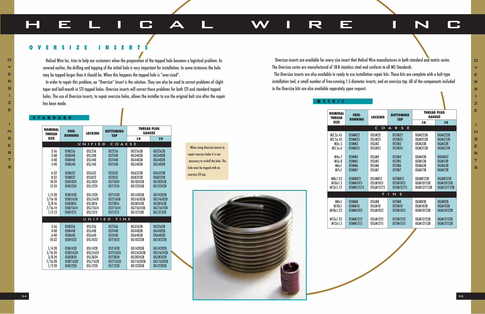
Helical Wire Inc. tries to help our customers when the preparation of the tapped hole becomes a logistical problem. Ascovered earlier, the drilling and tapping of the initial hole is very important for installation. In some instances the holemay be tapped larger than it should be. When this happens the tapped hole is “over-sized”.In order to repair this problem, an “Oversize” Insert is the solution. They can also be used to correct problems of slight
taper and bell-mouth in STI tapped holes. Oversize inserts will correct these problems for both STI and standard tappedholes. The use of Oversize inserts, to repair oversize holes, allows the installer to use the original bolt size after the repairhas been made.
Oversize inserts are available for every size insert that Helical Wire manufactures in both standard and metric series.The Oversize series are manufactured of 18-8 stainless steel and conform to all MS Standards. The Oversize inserts are also available in ready to use installation repair kits. These kits are complete with a bolt type installation tool, a small number of free-running 1.5 diameter inserts, and an oversize tap. All of the components includedin the Oversize kits are also available separately upon request.
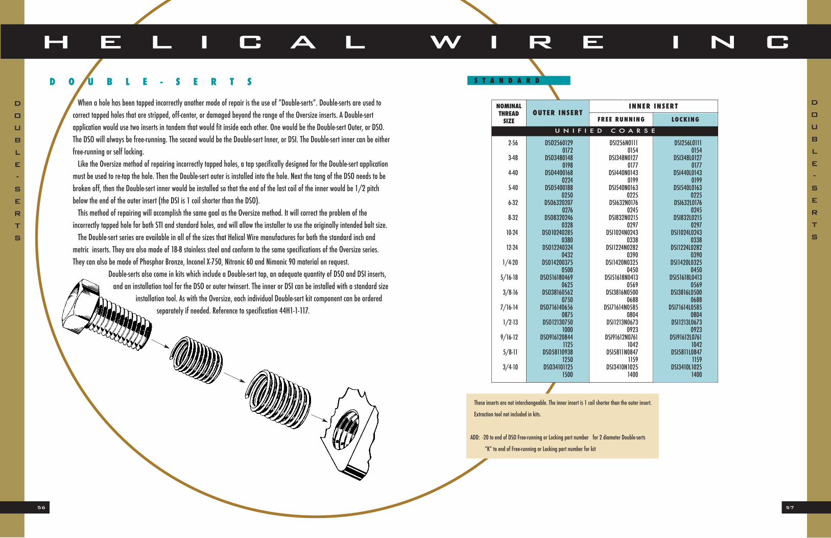
These inserts are not interchangeable. The inner insert is 1 coil shorter than the outer insert.
Extraction tool not included in kits.
ADD: -20 to end of DSO Free-running or Locking part number for 2 diameter Double-serts
“K” to end of Free-running or Locking part number for kit
S T A N D A R D
When a hole has been tapped incorrectly another mode of repair is the use of “Double-serts”. Double-serts are used tocorrect tapped holes that are stripped, off-center, or damaged beyond the range of the Oversize inserts. A Double-sert application would use two inserts in tandem that would fit inside each other. One would be the Double-sert Outer, or DSO.The DSO will always be free-running. The second would be the Double-sert Inner, or DSI. The Double-sert inner can be eitherfree-running or self locking.Like the Oversize method of repairing incorrectly tapped holes, a tap specifically designed for the Double-sert application
must be used to re-tap the hole. Then the Double-sert outer is installed into the hole. Next the tang of the DSO needs to bebroken off, then the Double-sert inner would be installed so that the end of the last coil of the inner would be 1/2 pitchbelow the end of the outer insert (the DSI is 1 coil shorter than the DSO). This method of repairing will accomplish the same goal as the Oversize method. It will correct the problem of the
incorrectly tapped hole for both STI and standard holes, and will allow the installer to use the originally intended bolt size.The Double-sert series are available in all of the sizes that Helical Wire manufactures for both the standard inch and
metric inserts. They are also made of 18-8 stainless steel and conform to the same specifications of the Oversize series.They can also be made of Phosphor Bronze, Inconel X-750, Nitronic 60 and Nimonic 90 material on request.
Double-serts also come in kits which include a Double-sert tap, an adequate quantity of DSO and DSI inserts,and an installation tool for the DSO or outer twinsert. The inner or DSI can be installed with a standard size
installation tool. As with the Oversize, each individual Double-sert kit component can be orderedseparately if needed. Reference to specification 44H1-1-117.
Helical Wire Inc. manufactures inserts in as many sizes and types as we possibly can, even some that are hard to find.We refer to these as “Specials”. We manufacture exceptional sizes tomeet the exact needs of certain customers. These inserts are designed and manufactured for specific mechanical needs.The Automotive inserts are sizes that are commonly used in
automotive manufacturing. They are frequently used in the assembly of particular engine components, such as carburetor units.They are an integral part of the quality required by major Auto makers to fabricate the best possible products.The Pipe Thread series are available in a complete range of sizes
for the most frequent use of correcting taper pipe thread failureswhich can occur in such applications as exhaust pipes on small engines.The Spark Plug inserts provide the most durable and highest quality repair available for professional mechanics and
engine rebuilders. Helical Wire manufactures Spark Plug inserts for any size engine. They are the preferred method of repair specified by virtually all U.S. and foreign vehicle manufacturers.The listings below are examples of the different size needs for applications of various special inserts.
9M x 1.25 N XXX SPM9XXX10M x 1.0 N XXX SPM10XXX12M x 1.0 N XXX SPM12XXX
11M x 1.0 N XXX SPM1110XXX11M x 1.25 N XXX SPM11125XXX11M x 1.5 N XXX SPM1115XXX
14M x 1.25 N 3/8 SPM143814M x 1.25 N 437 SPM1443714M x 1.25 N 500 SPM1450014M x 1.25 N 750 SPM14750
18M x 1.5 N 500 SPM18500
NOMINALTHREADSIZE
S P A R K P L U G S
HELICAL WIREPART NUMBER
1/8-27 PT18271/4-18 PT14183/8-18 PT3818
1/2-14 PT12143/4-14 PT3414
1-11-1/2 PT11112
NOMINALTHREADSIZE
P I P E T H R E A D
HELICAL WIREPART NUMBER
1-20 N 325 1203257/8-20 N 330 782033012-28 N XXX 1228XXX
7/8-18 N XXX 7818XXX11/16-16 N XXX 111616XXX
NOMINALTHREADSIZE
A U T O M O T I V E
HELICAL WIREPART NUMBER
Helical Wire Inc. can also manufacture special sized inserts in various sizes not shown. Some special sizes may be uncommon
dimensions or thread sizes for unique applications and circumstances. These specials would require additional lead time for
production, and would also require a mechanical set up fee that would be determined upon quoting of the individual item.
Helical Wire Inc. also manufactures 8-Pitch inserts. These inserts are designed specifically for 8-pitch holes in order to reduce the pitch diameter of a standard 8-pitch tapped thread for use with original application and repairs. This reductionis by exactly 1/8” so that repairs can be made in normal 1/8” thread-size increments. A damaged hole can be repaired by tapping with the next 1/8” larger standard 8-pitch tap. After the insert is installed, a permanently repaired thread is provided to the original size with no special taps ever needed. This method of thread repair is quick, economical and provides better threads than the original without scrapping expensive parts and very little down-time.We manufacture these inserts of 18-8 stainless steel per AS7245 and Inconel X-750 per AS7246 in Standard Free-running
and Self-locking inserts sizes 1-1/8 to 2” in lengths of 1, 1-1/2 and 2 times the nominal diameter. Other lengths can bemade to special order.