Page 1
UNITED STATES DISTRICT COURT FOR THE DISTRICT OF MINNESOTA
COMMSCOPE TECHNOLOGIES LLC Plaintiffs, v. CLEARFIELD, INC., Defendant.
) ) ) ) ) ) ) ) ) )
No. __________________ Jury Trial Demanded
Complaint
This is a complaint for patent infringement. Plaintiff CommScope Technologies
LLC (“CommScope”) brings this action against Defendant Clearfield, Inc. (“Clearfield”)
and state as follows.
Parties
1. CommScope Technologies LLC, formerly known as Andrew LLC, is a
Delaware company, headquartered in Hickory, North Carolina with a place of business in
this district at 501 Shenandoah Dr., Shakopee, Minnesota. Together with its affiliated
companies, CommScope designs, manufactures, and sells telecommunications products
and equipment around the world. CommScope’s innovative products are used to build
network infrastructures that enable wired and wireless communications. CommScope’s
products can be found in large buildings, venues and outdoor spaces; in data centers and
buildings of all shapes, sizes and complexity; at wireless cell sites; in telecom central
offices and cable headends; and in FTTx deployments.
CASE 0:17-cv-00307 Document 1 Filed 01/31/17 Page 1 of 77
Page 2
2
2. Clearfield is a Minnesota corporation having a principal place of business
at 7050 Winnetka Avenue North, Suite 100, Brooklyn Park, Minnesota 55428.
Jurisdiction
3. This action arises under the Patent Act, 35 U.S.C. § 271 et seq.
4. This Court has subject matter jurisdiction under 28 U.S.C. §§ 1331 and
1338(a).
5. This Court has personal jurisdiction over Clearfield. Clearfield is a resident
of Minnesota and maintains an office and transacts business within Minnesota. Upon
information and belief, Clearfield does business and has committed acts of infringement
in this district.
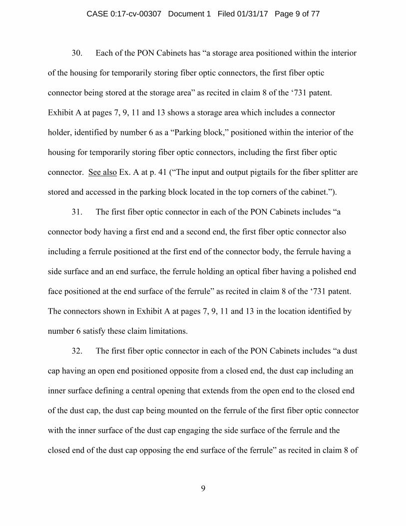
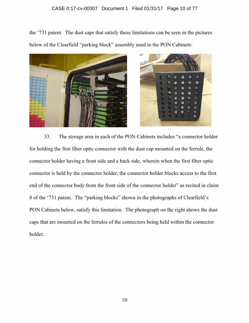
6. Venue is proper in this district under 28 U.S.C. §§ 1391 and 1400(b).
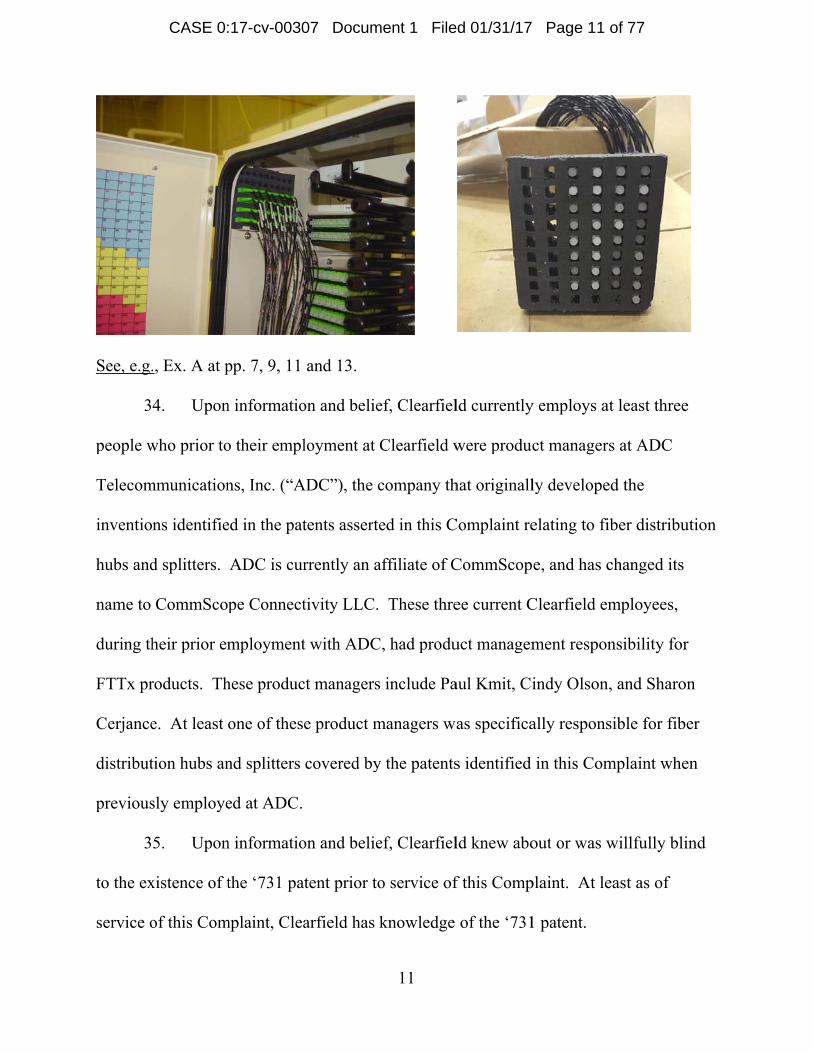
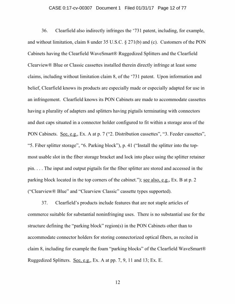
Clearfield resides in this district. Upon information and belief, Clearfield has committed
acts of infringement in this district and has a regular and established place of business in
this district.
Clearfield’s Infringing Products and Activities
7. Clearfield has committed acts of patent infringement by making, using,
selling, offering for sale, and/or importing into the United States telecommunications
connection cabinets and components therefore. Clearfield’s infringing
telecommunications connection cabinets include, without limitation, the FieldSmart®
Fiber Scalability Center 288 PON Cabinet, FieldSmart® Fiber Scalability Center 432
PON Cabinet, FieldSmart® Fiber Scalability Center 576 PON Cabinet, and FieldSmart®
Fiber Scalability Center 1152 PON Cabinet (together “PON Cabinets”). Clearfield’s
CASE 0:17-cv-00307 Document 1 Filed 01/31/17 Page 2 of 77
Page 3
3
infringing telecommunications components include, without limitation, the Clearfield
WaveSmart® Ruggedized Splitters.
8. A copy of Clearfield’s Installation Manual for the PON Cabinets is attached
as Exhibit A. Exhibit A is accessible through
http://www.clearfieldconnection.com/products/cabinets/pon-cabinets.html, which is a
link provided on Clearfield’s website http://www.clearfieldconnection.com. Upon
information and belief, Clearfield believes that the product information for the PON
Cabinets in Exhibit A is accurate.
9. A copy of Clearfield’s Data Sheet for the PON Cabinets is attached as
Exhibit B. Exhibit B is accessible through
http://www.clearfieldconnection.com/products/cabinets/pon-cabinets.html, which is a
link provided on Clearfield’s website http://www.clearfieldconnection.com. Upon
information and belief, Clearfield believes that the product information for the PON
Cabinets in Exhibit B is accurate.
10. PON Cabinets use Clearfield Clearview® Blue and Clearview® Classic
cassettes. A copy of Clearfield’s Data Sheets for the Clearfield Clearview® Blue and
Clearview® Classic cassettes are attached as Exhibits C and D, respectively. Exhibits C
and D are accessible through
http://www.clearfieldconnection.com/products/cassettes.html, which is a link provided on
Clearfield’s website http://www.clearfieldconnection.com. Upon information and belief,
Clearfield believes that the product information for the Clearview® Blue and Clearview®
Classic cassettes in Exhibits C and D is accurate.
CASE 0:17-cv-00307 Document 1 Filed 01/31/17 Page 3 of 77
Page 4
4
11. Upon information and belief, PON Cabinets are offered for sale and sold by
Clearfield with one or more of the Clearview® Blue and/or Clearview® Classic cassettes
installed therein.
12. PON Cabinets use Clearfield WaveSmart® Ruggedized Splitters. A copy
of Clearfield’s Data Sheet for the Clearfield WaveSmart® Ruggedized Splitters is
attached as Exhibit E. Exhibit E is accessible through
http://www.clearfieldconnection.com/products/optical-components/osp-splitters.html,
which is a link provided on Clearfield’s website http://www.clearfieldconnection.com.
Upon information and belief, Clearfield believes that the product information for the
Clearfield WaveSmart® Ruggedized Splitters in Exhibit E is accurate.
13. Clearfield has committed acts of patent infringement by making, using,
selling, offering for sale, and/or importing into the United States telecommunication
connectors. Clearfield’s infringing telecommunication connectors include, without
limitation, the FieldShield SmarTerminal Hardened Pushable Connectors (“FieldShield
Hardened Connector”). Upon information and belief, the FieldShield Hardened
Connector is sold and/or used in connection with multiple pushable connectors, including
for example LC, SC, and MPO connector types.
14. A copy of Clearfield’s Data Sheet for the FieldShield Hardened Connector
is attached as Exhibit F. Exhibit F is accessible through
http://www.clearfieldconnection.com/products/pushable-fiber/fs-hardened-
connectors.html, which is a link provided on Clearfield’s website
http://www.clearfieldconnection.com. Upon information and belief, Clearfield believes
CASE 0:17-cv-00307 Document 1 Filed 01/31/17 Page 4 of 77
Page 5
5
that the product information for the FieldShield Hardened Connector in Exhibit F is
accurate.
15. Clearfield has committed acts of patent infringement by making, using,
selling, offering for sale, and/or importing into the United States telecommunication
boxes and components. Clearfield’s infringing telecommunication boxes and
components include, without limitation, the FieldShield® StrongFiber Deploy Reel and
Wall Box (“FieldShield® Deploy Reel and Box”).
16. A copy of Clearfield’s Data Sheet for the FieldShield® Deploy Reel and
Box is attached as Exhibit G. Exhibit G is accessible at
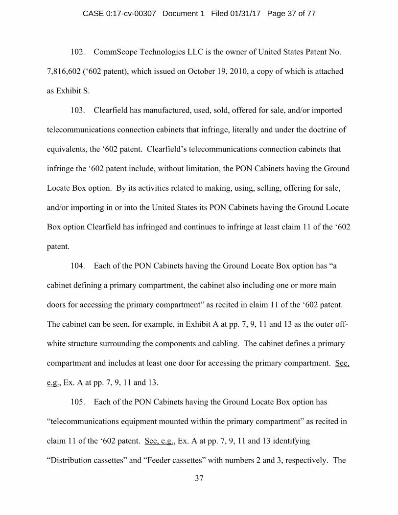
http://www.clearfieldconnection.com/downloads/data-sheets/fs-st-deploy-reel.pdf, which
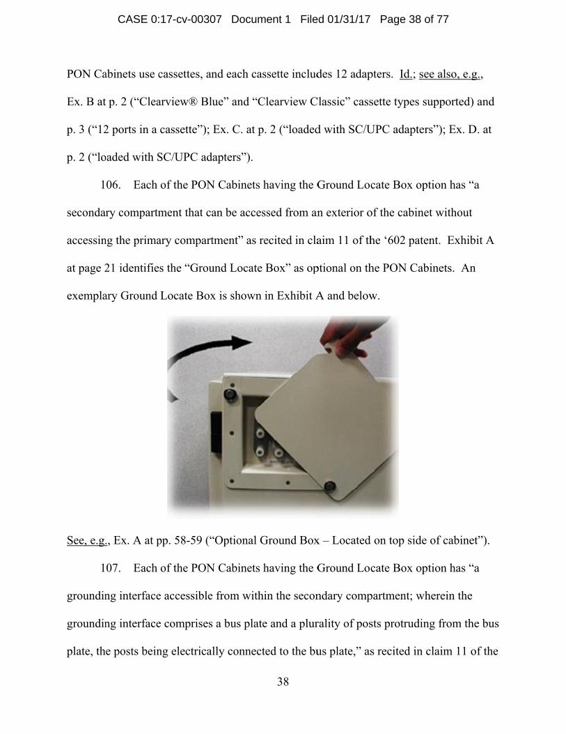
is a link provided on Clearfield’s website http://www.clearfieldconnection.com. Upon
information and belief, Clearfield believes that the product information for the
FieldShield® Deploy Reel and Box in Exhibit G is accurate. Upon information and
belief, the FieldShield® Deploy Reel and Box are used, offered for sale, and/or sold
together.
17. Clearfield has committed acts of patent infringement by making, using,
selling, offering for sale, and/or importing into the United States telecommunication
panels. Clearfield’s infringing telecommunication panels include, without limitation, the
SmartRoute 1RU 24 Port Panel (“SmartRoute Panel”).
18. A copy of Clearfield’s Data Sheet for the SmartRoute Panel is attached as
Exhibit H. Exhibit H is accessible through
http://www.clearfieldconnection.com/products/panels/smartroute-panel.html, which is a
CASE 0:17-cv-00307 Document 1 Filed 01/31/17 Page 5 of 77
Page 6
6
link provided on Clearfield’s website http://www.clearfieldconnection.com. Upon
information and belief, Clearfield believes that the product information for the
SmartRoute Panel in Exhibit H is accurate.
19. Clearfield has committed acts of patent infringement by making, using,
selling, offering for sale, and/or importing into the United States telecommunication
terminals. Clearfield’s infringing telecommunication terminals include, without
limitation, the FieldShield Multiport SmarTerminal. The FieldShield Multiport
SmarTerminal is offered for sale and sold in several configurations. For example, the
FieldShield MultiPort SmarTerminal has an Optical Components-Splitter configuration, a
Patch Only configuration, and a Patch and Splice configuration.
20. A copy of Clearfield’s Data Sheet for the FieldShield® SmarTerminal
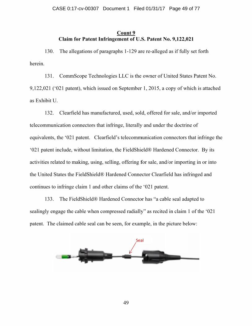
Optical Components configuration is attached as Exhibit I. Exhibit I is accessible
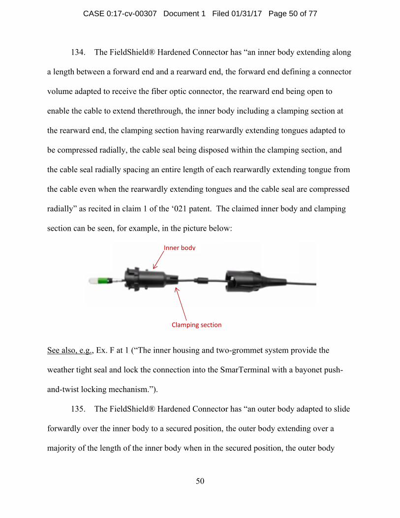
through http://www.clearfieldconnection.com/products/terminals/smarterminal.html,
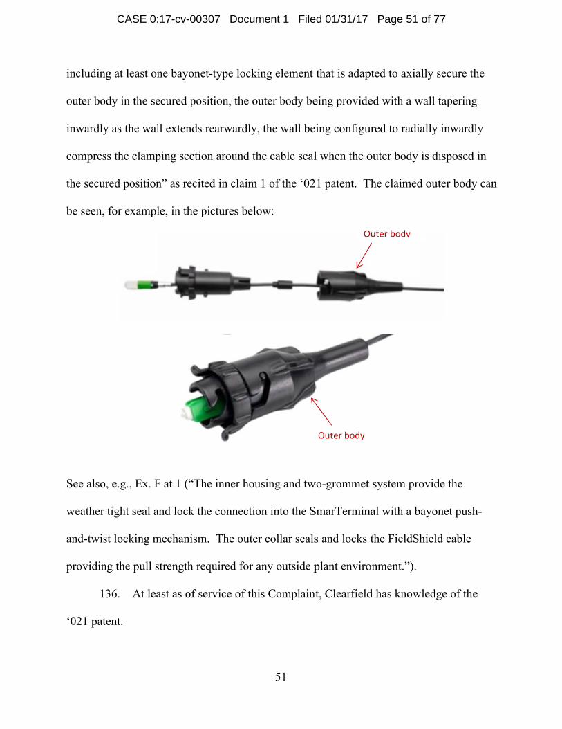
which is a link provided on Clearfield’s website http://www.clearfieldconnection.com.
Upon information and belief, Clearfield believes that the product information for the
FieldShield® SmarTerminal Optical Components in Exhibit I is accurate.
21. A copy of Clearfield’s Data Sheet for the FieldShield® SmarTerminal
Patch and Splice configuration is attached as Exhibit J. Exhibit J is accessible through
http://www.clearfieldconnection.com/products/terminals/smarterminal.html, which is a
link provided on Clearfield’s website http://www.clearfieldconnection.com. Upon
information and belief, Clearfield believes that the product information for the
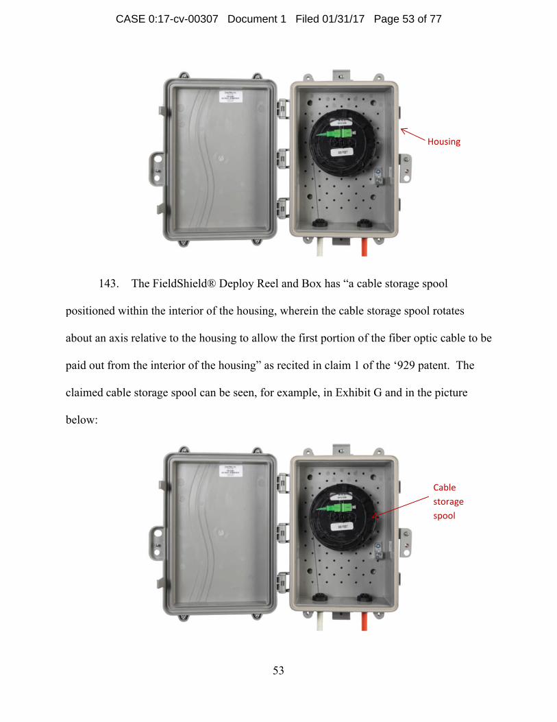
FieldShield® SmarTerminal Patch and Splice in Exhibit J is accurate.
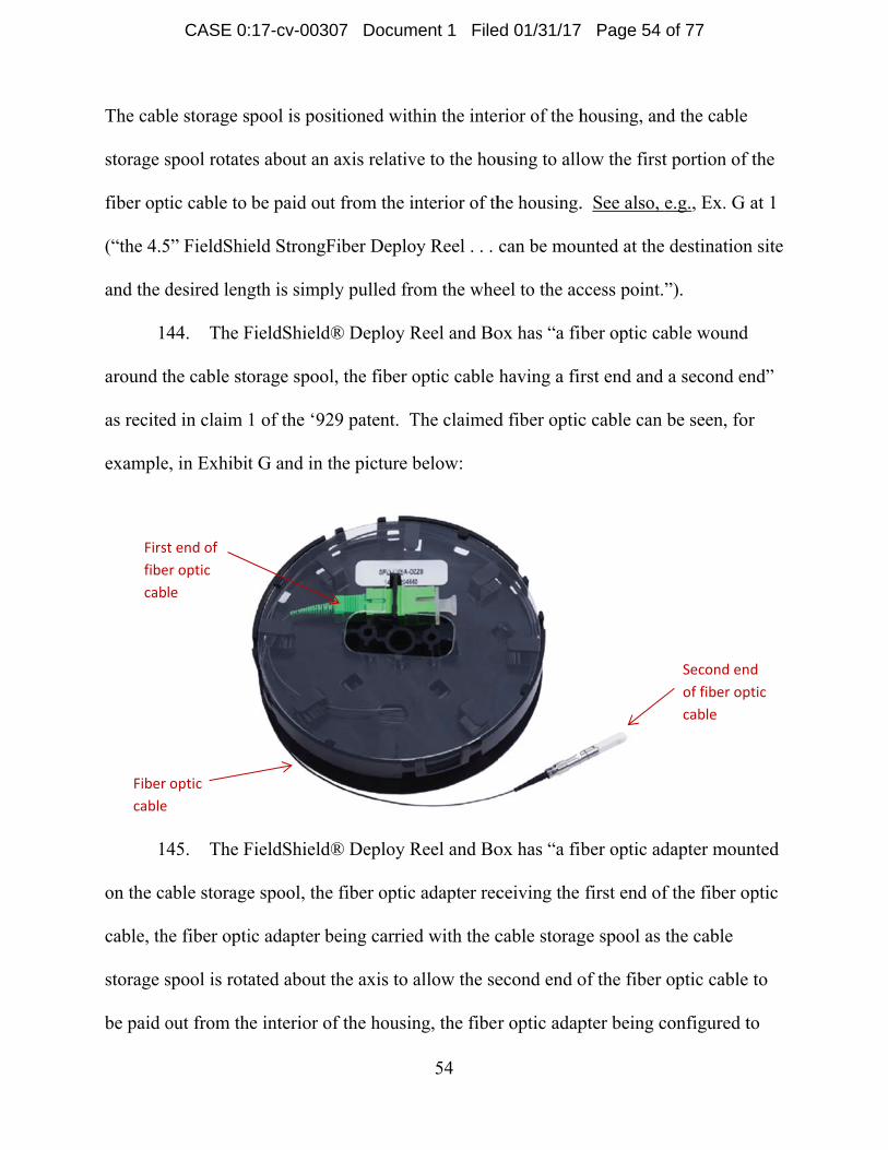
CASE 0:17-cv-00307 Document 1 Filed 01/31/17 Page 6 of 77
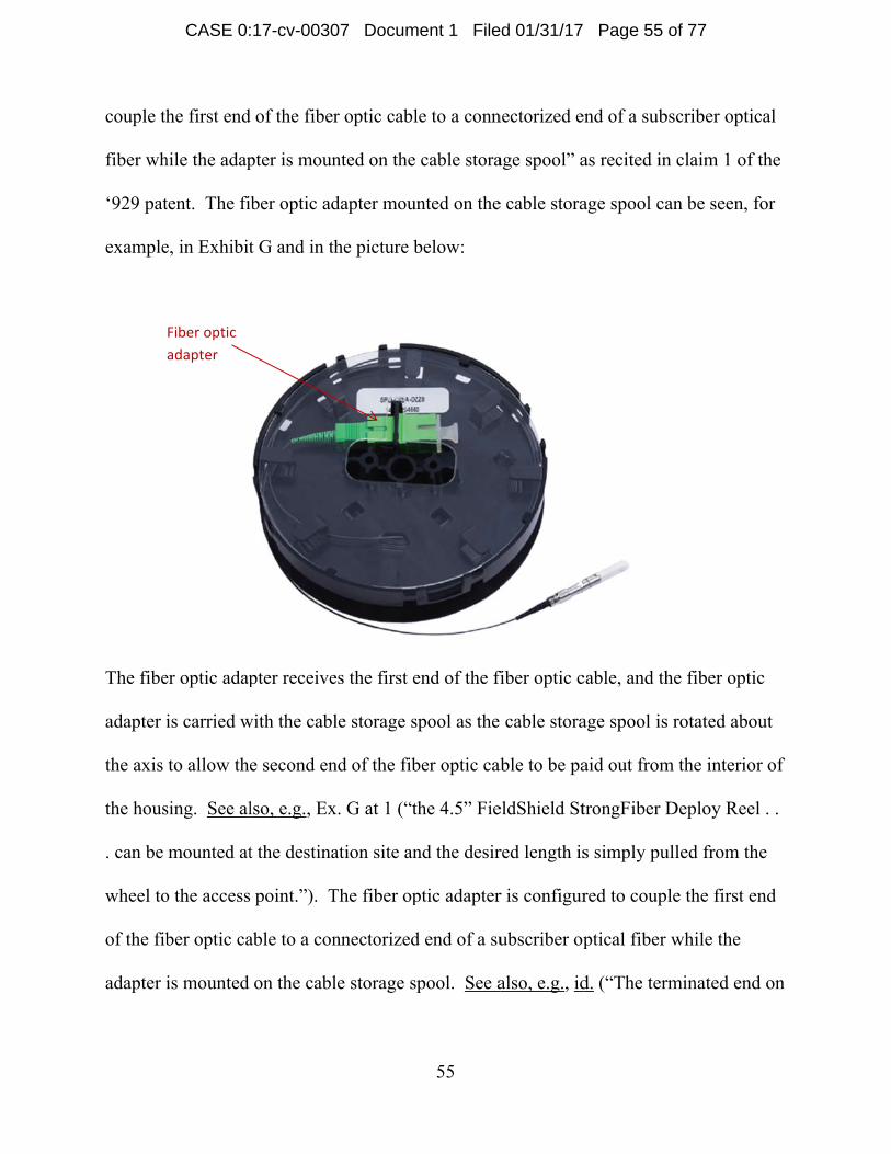
Page 7
7
22. A copy of Clearfield’s Data Sheet for the FieldShield® SmarTerminal
Patch Only configuration is attached as Exhibit K. Exhibit K is accessible through
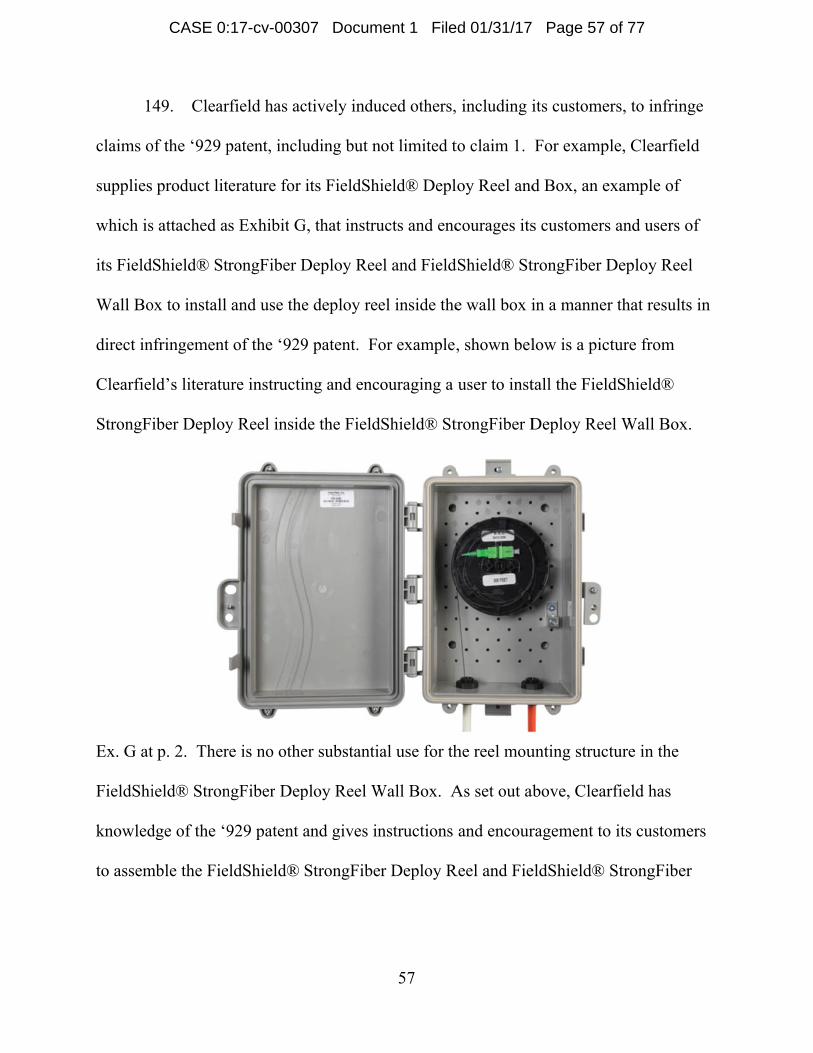
http://www.clearfieldconnection.com/products/terminals/smarterminal.html, which is a
link provided on Clearfield’s website http://www.clearfieldconnection.com. Upon
information and belief, Clearfield believes that the product information for the
FieldShield® SmarTerminal Patch Only in Exhibit K is accurate.
23. A copy of Clearfield’s Installation Manual for the FieldShield Multiport
SmarTerminals is attached as Exhibit L. Exhibit L is accessible through
http://www.clearfieldconnection.com/products/terminals/smarterminal.html, which is a
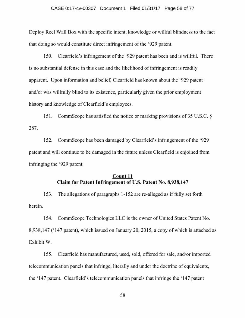
link provided on Clearfield’s website http://www.clearfieldconnection.com. Upon
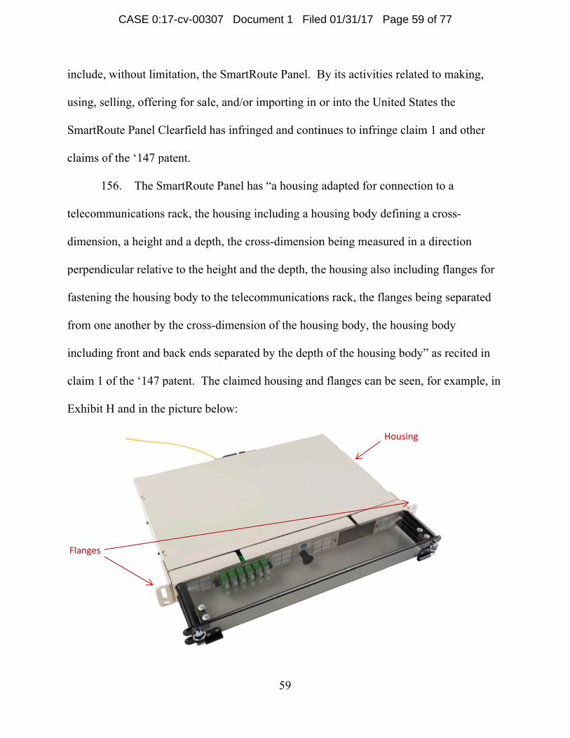
information and belief, Clearfield believes that the product information for the
FieldShield Multiport SmarTerminals in Exhibit L is accurate.
Count 1 Claim for Patent Infringement of U.S. Patent No. 7,233,731
24. The allegations of paragraphs 1-23 are re-alleged as if fully set forth herein.
25. CommScope Technologies LLC is the owner of United States Patent No.
7,233,731 (‘731 patent), which issued on June 19, 2007, a copy of which is attached as
Exhibit M.
26. Clearfield has manufactured, used, sold, offered for sale, and/or imported
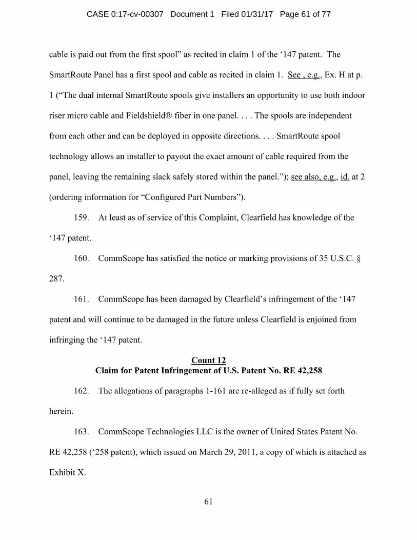
telecommunications connection cabinets that infringe, literally and under the doctrine of
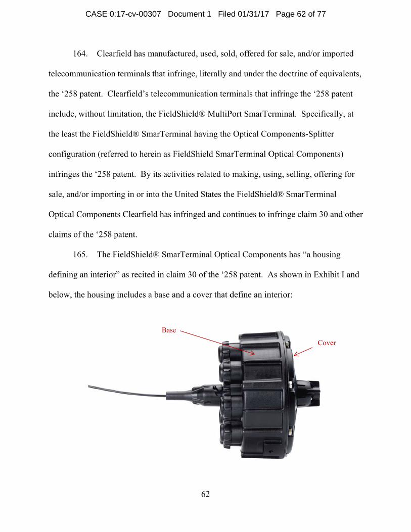
equivalents, the ‘731 patent. Clearfield’s telecommunications connection cabinets that
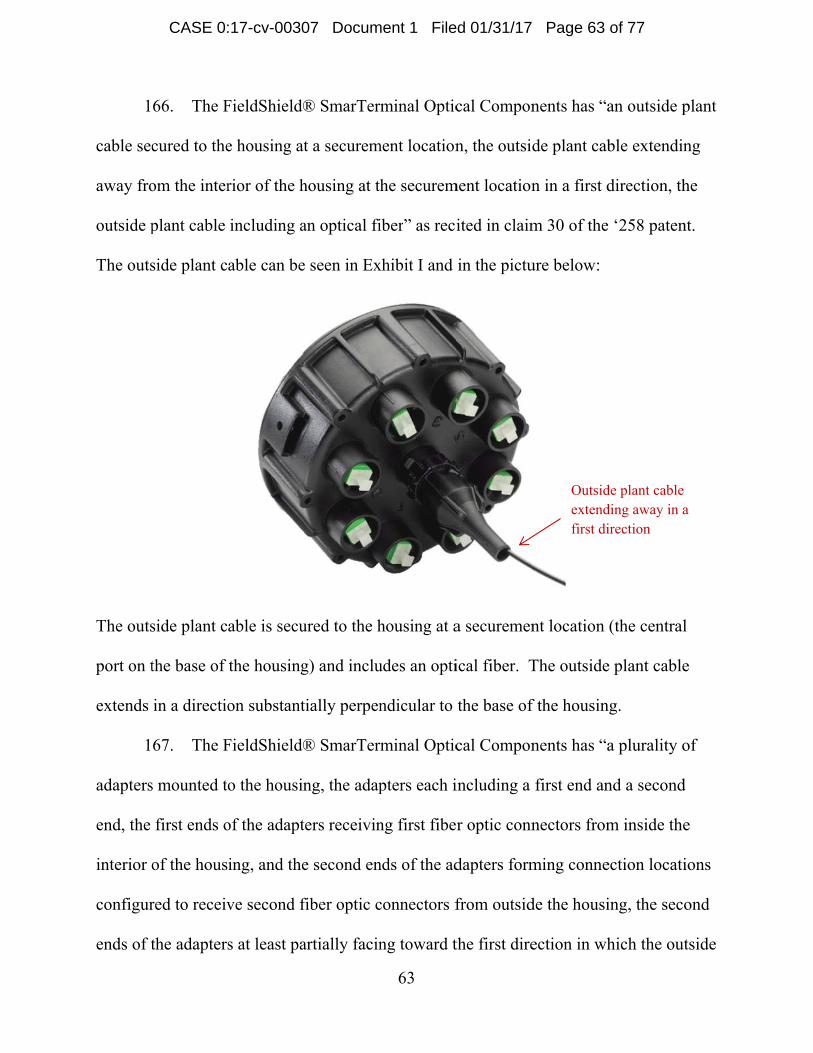
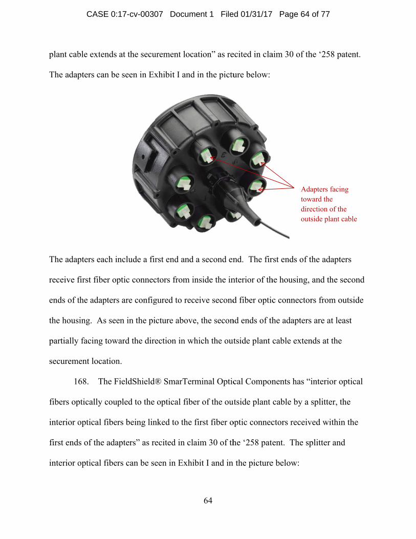
infringe the ‘731 patent include, without limitation, the PON Cabinets. By its activities
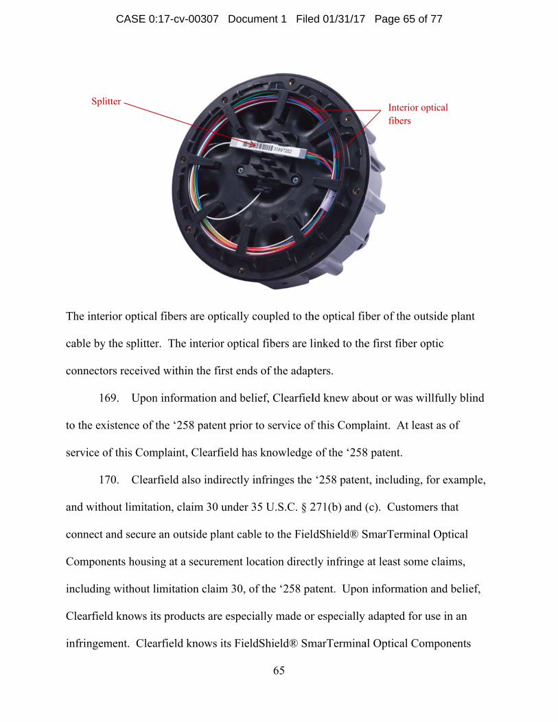
CASE 0:17-cv-00307 Document 1 Filed 01/31/17 Page 7 of 77
Page 8
8
related to making, using, selling, offering for sale, and/or importing in or into the United
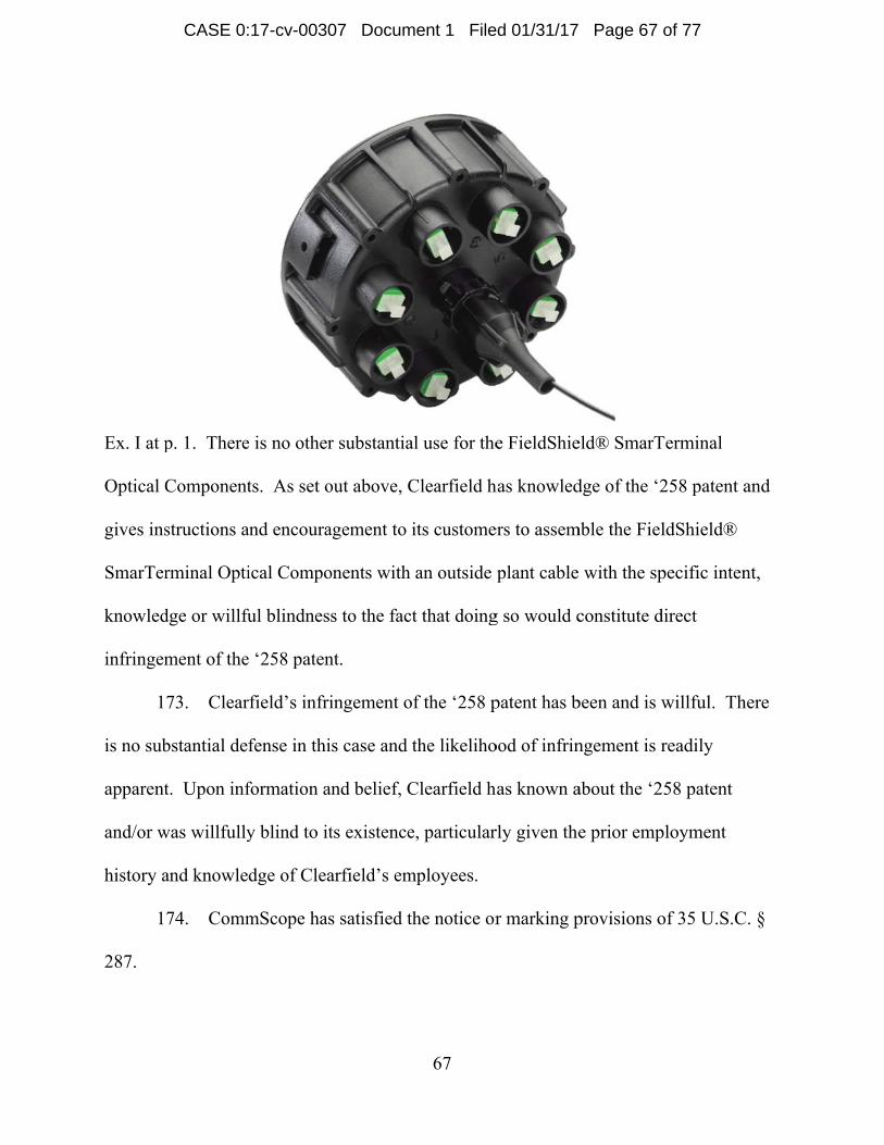
States its PON Cabinets Clearfield has infringed and continues to infringe claim 8 and
other claims of the ‘731 patent.
27. Each of the PON Cabinets has a “housing including a front opening for
accessing an interior of the housing, the housing also including a front door for opening
and closing the front opening” as recited in claim 8 of the ‘731 patent. The housing and
front door can be seen, for example, in Exhibit A at pp. 7, 9, 11 and 13 as the outer off-
white structure surrounding the components and cabling.
28. Each of the PON Cabinets has “an array of telecommunications adapters
mounted within the interior of the housing, each telecommunications adapter being
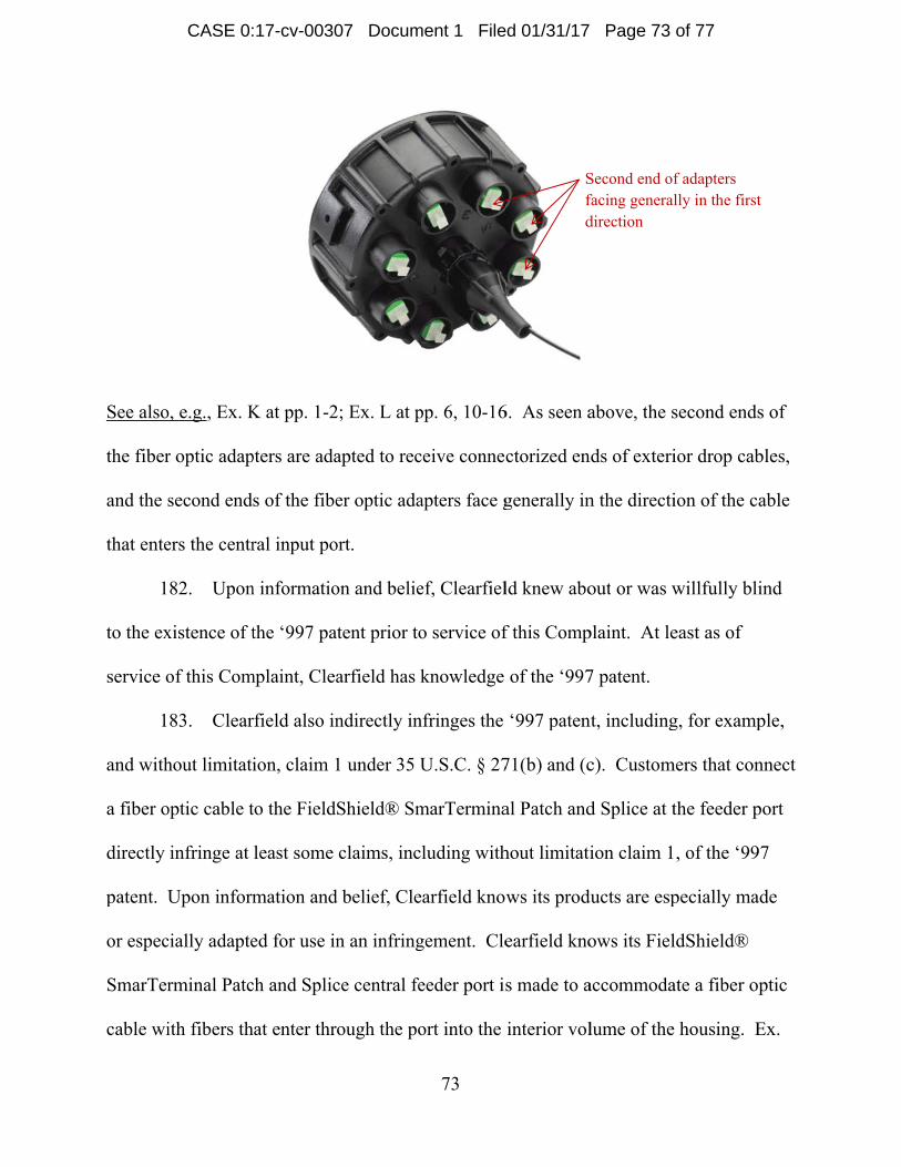
configured for coupling together two fiber optic connectors such that an optical
interconnection is made between the two fiber optic connectors” as recited in claim 8 of
the ‘731 patent. See, e.g., Ex. A at pp. 7, 9, 11 and 13 identifying “Distribution cassettes”
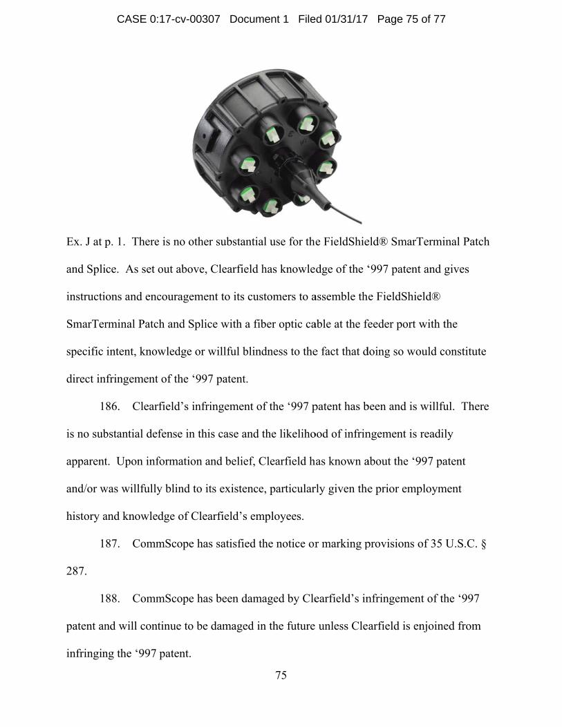
and “Feeder cassettes” with numbers 2 and 3, respectively. The PON Cabinets use
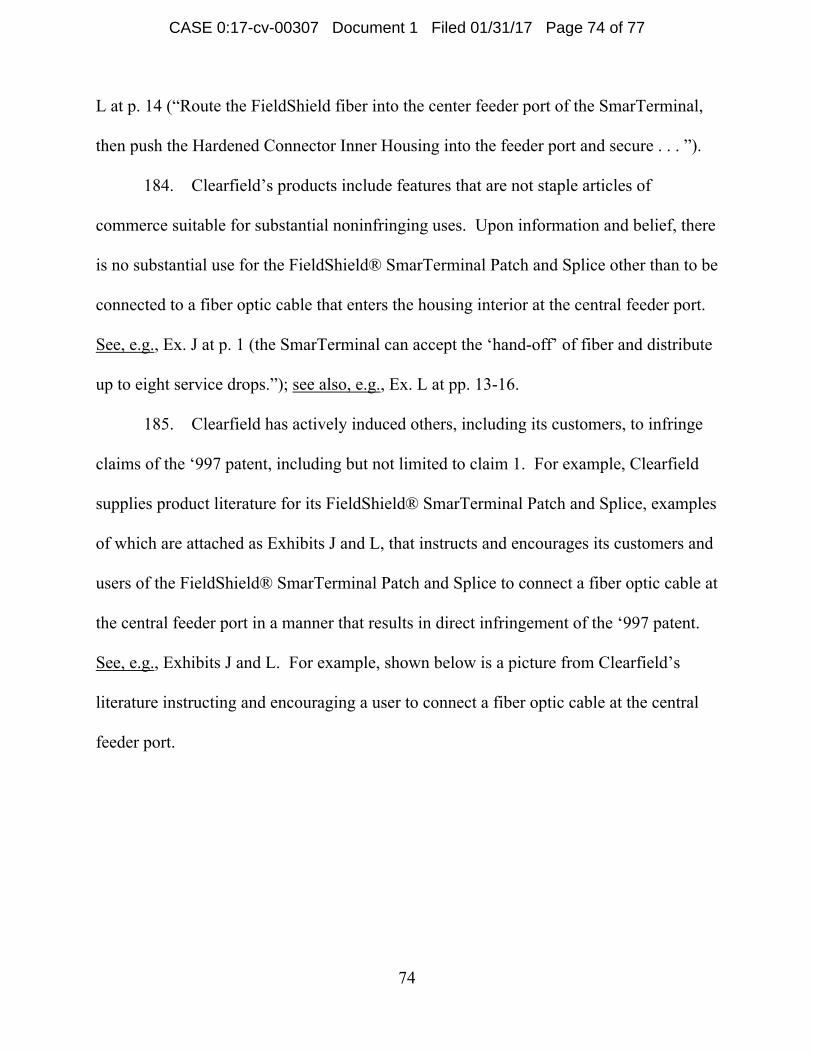
cassettes, and each cassette includes 12 adapters. Id.; see also, e.g., Ex. B at p. 2
(“Clearview® Blue” and “Clearview Classic” cassette types supported) and 3 (“12 ports
in a cassette”); Ex. C. at p. 2 (“loaded with SC/UPC adapters”); Ex. D. at p. 2 (“loaded
with SC/UPC adapters”).
29. Each of the PON Cabinets has “a first fiber optic cord having an end that
terminates at a first fiber optic connector” as recited in claim 8 of the ‘731 patent.
Exhibit A at pages 7, 9, 11 and 13 shows a fiber optic cord having an end that terminates
at a green fiber optic connector in the location identified by number 6.
CASE 0:17-cv-00307 Document 1 Filed 01/31/17 Page 8 of 77
Page 9
9
30. Each of the PON Cabinets has “a storage area positioned within the interior
of the housing for temporarily storing fiber optic connectors, the first fiber optic
connector being stored at the storage area” as recited in claim 8 of the ‘731 patent.
Exhibit A at pages 7, 9, 11 and 13 shows a storage area which includes a connector
holder, identified by number 6 as a “Parking block,” positioned within the interior of the
housing for temporarily storing fiber optic connectors, including the first fiber optic
connector. See also Ex. A at p. 41 (“The input and output pigtails for the fiber splitter are
stored and accessed in the parking block located in the top corners of the cabinet.”).
31. The first fiber optic connector in each of the PON Cabinets includes “a
connector body having a first end and a second end, the first fiber optic connector also
including a ferrule positioned at the first end of the connector body, the ferrule having a
side surface and an end surface, the ferrule holding an optical fiber having a polished end
face positioned at the end surface of the ferrule” as recited in claim 8 of the ‘731 patent.
The connectors shown in Exhibit A at pages 7, 9, 11 and 13 in the location identified by
number 6 satisfy these claim limitations.
32. The first fiber optic connector in each of the PON Cabinets includes “a dust
cap having an open end positioned opposite from a closed end, the dust cap including an
inner surface defining a central opening that extends from the open end to the closed end
of the dust cap, the dust cap being mounted on the ferrule of the first fiber optic connector
with the inner surface of the dust cap engaging the side surface of the ferrule and the
closed end of the dust cap opposing the end surface of the ferrule” as recited in claim 8 of
CASE 0:17-cv-00307 Document 1 Filed 01/31/17 Page 9 of 77
Page 10
the ‘731
below of
3
for holdi
connecto
connecto
end of th
8 of the
PON Ca
caps tha
holder.
patent. Th
f the Clearf
3. The s
ing the first
or holder ha
or is held by
he connecto
‘731 patent
abinets belo
t are mount
he dust caps
field “parkin
storage area
t fiber optic
aving a fron
y the conne
or body from
t. The “par
ow, satisfy t
ted on the f
s that satisfy
ng block” a
a in each of
c connector
nt side and a
ector holder
m the front
rking blocks
this limitatio
ferrules of th
10
y these limi
assembly us
the PON C
with the du
a back side
r, the conne
side of the
s” shown in
on. The ph
he connecto
itations can
sed in the P
Cabinets inc
ust cap mou
, wherein w
ector holder
connector h
n the photog
hotograph o
ors being he
n be seen in
PON Cabine
cludes “a co
unted on the
when the fir
r blocks acc
holder” as r
graphs of C
n the right
eld within t
the picture
ets:
onnector hol
e ferrule, th
rst fiber opt
cess to the f
recited in cl
Clearfield’s
shows the d
the connect
es
lder
he
ic
first
laim
dust
or
CASE 0:17-cv-00307 Document 1 Filed 01/31/17 Page 10 of 77
Page 11
See, e.g.
3
people w
Telecom
inventio
hubs and
name to
during th
FTTx pr
Cerjance
distribut
previous
3
to the ex
service o
., Ex. A at p
4. Upon
who prior to
mmunication
ns identifie
d splitters.
CommSco
heir prior em
roducts. Th
e. At least
tion hubs an
sly employe
5. Upon
xistence of t
of this Com
pp. 7, 9, 11
n informatio
o their empl
ns, Inc. (“A
ed in the pat
ADC is cur
pe Connect
mployment
hese produc
one of these
nd splitters
ed at ADC.
n informatio
the ‘731 pa
mplaint, Clea
and 13.
on and belie
loyment at C
ADC”), the c
tents asserte
rrently an a
tivity LLC.
t with ADC
ct managers
e product m
covered by
on and belie
tent prior to
arfield has k
11
ef, Clearfiel
Clearfield w
company th
ed in this C
affiliate of C
These thre
C, had produ
include Pa
managers wa
y the patents
ef, Clearfiel
o service of
knowledge
ld currently
were produc
hat originall
Complaint re
CommScop
ee current C
uct managem
aul Kmit, Ci
as specifica
s identified
ld knew abo
f this Comp
of the ‘731
y employs a
ct manager
ly develope
elating to fi
e, and has c
Clearfield em
ment respon
indy Olson
ally respons
in this Com
out or was w
plaint. At le
1 patent.
at least three
s at ADC
ed the
iber distribu
changed its
mployees,
nsibility for
, and Sharo
sible for fib
mplaint whe
willfully bli
east as of
e
ution
r
on
ber
en
ind
CASE 0:17-cv-00307 Document 1 Filed 01/31/17 Page 11 of 77
Page 12
12
36. Clearfield also indirectly infringes the ‘731 patent, including, for example,
and without limitation, claim 8 under 35 U.S.C. § 271(b) and (c). Customers of the PON
Cabinets having the Clearfield WaveSmart® Ruggedized Splitters and the Clearfield
Clearview® Blue or Classic cassettes installed therein directly infringe at least some
claims, including without limitation claim 8, of the ‘731 patent. Upon information and
belief, Clearfield knows its products are especially made or especially adapted for use in
an infringement. Clearfield knows its PON Cabinets are made to accommodate cassettes
having a plurality of adapters and splitters having pigtails terminating with connectors
and dust caps situated in a connector holder configured to fit within a storage area of the
PON Cabinets. See, e.g., Ex. A at p. 7 (“2. Distribution cassettes”, “3. Feeder cassettes”,
“5. Fiber splitter storage”, “6. Parking block”), p. 41 (“Install the splitter into the top-
most usable slot in the fiber storage bracket and lock into place using the splitter retainer
pin. . . . The input and output pigtails for the fiber splitter are stored and accessed in the
parking block located in the top corners of the cabinet.”); see also, e.g., Ex. B at p. 2
(“Clearview® Blue” and “Clearview Classic” cassette types supported).
37. Clearfield’s products include features that are not staple articles of
commerce suitable for substantial noninfringing uses. There is no substantial use for the
structure defining the “parking block” region(s) in the PON Cabinets other than to
accommodate connector holders for storing connectorized optical fibers, as recited in
claim 8, including for example the foam “parking blocks” of the Clearfield WaveSmart®
Ruggedized Splitters. See, e.g., Ex. A at pp. 7, 9, 11 and 13; Ex. E.
CASE 0:17-cv-00307 Document 1 Filed 01/31/17 Page 12 of 77
Page 13
3
claims o
supplies
and asso
that instr
cabinets
caps, an
‘731 pat
PON Ca
There is
out abov
encourag
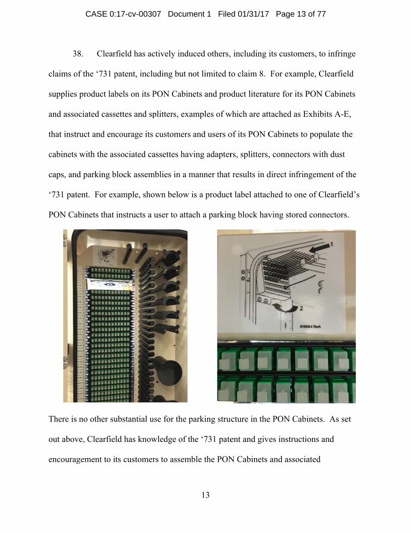
8. Clear
of the ‘731 p
product lab
ociated cass
ruct and en
with the as
d parking b
tent. For ex
abinets that
no other su
ve, Clearfie
gement to i
rfield has ac
patent, inclu
bels on its P
settes and sp
courage its
ssociated ca
block assem
xample, sho
instructs a
ubstantial u
ld has know
ts customer
ctively indu
uding but n
PON Cabin
plitters, exa
customers
assettes hav
mblies in a m
own below i
user to atta
use for the p
wledge of th
rs to assemb
13
uced others,
not limited t
nets and pro
amples of w
and users o
ving adapter
manner that
is a product
ch a parkin
parking stru
he ‘731 pate
ble the PON
including i
to claim 8.
oduct literatu
which are att
of its PON C
rs, splitters,
results in d
t label attac
ng block hav
ucture in the
ent and give
N Cabinets
its custome
For examp
ure for its P
tached as E
Cabinets to
, connectors
direct infrin
ched to one
ving stored
e PON Cabi
es instructio
and associa
ers, to infrin
ple, Clearfie
PON Cabin
Exhibits A-E
populate th
s with dust
ngement of t
of Clearfie
connectors
inets. As se
ons and
ated
nge
eld
ets
E,
he
the
eld’s
s.
et
CASE 0:17-cv-00307 Document 1 Filed 01/31/17 Page 13 of 77
Page 14
14
components with the specific intent, knowledge or willful blindness to the fact that doing
so would constitute direct infringement of the ‘731 patent.
39. Clearfield’s infringement of the ‘731 patent has been and is willful. There
is no substantial defense in this case and the likelihood of infringement is readily
apparent. Upon information and belief, Clearfield has known about the ‘731 patent
and/or was willfully blind to its existence, particularly given the prior employment
history and knowledge of Clearfield’s employees.
40. CommScope has satisfied the notice or marking provisions of 35 U.S.C. §
287.
41. CommScope has been damaged by Clearfield’s infringement of the ‘731
patent and will continue to be damaged in the future unless Clearfield is enjoined from
infringing the ‘731 patent.
Count 2 Claim for Patent Infringement of U.S. Patent No. 8,811,791
42. The allegations of paragraphs 1-41 are re-alleged as if fully set forth herein.
43. CommScope Technologies LLC is the owner of United States Patent No.
8,811,791 (‘791 patent), which issued on August 19, 2014, a copy of which is attached as
Exhibit N.
44. Clearfield has manufactured, used, sold, offered for sale, and/or imported
telecommunications connection cabinets that infringe, literally and under the doctrine of
equivalents, the ‘791 patent. Clearfield’s telecommunications connection cabinets that
infringe the ‘791 patent include, without limitation, the PON Cabinets. By its activities
CASE 0:17-cv-00307 Document 1 Filed 01/31/17 Page 14 of 77
Page 15
related t
States its
other cla
4
patent. T
outer off
4
housing,
includin
and 13 s
number
photogra
Exhibit A
4
housing
o making, u
s PON Cab
aims of the
5. Each
The housin
f-white stru
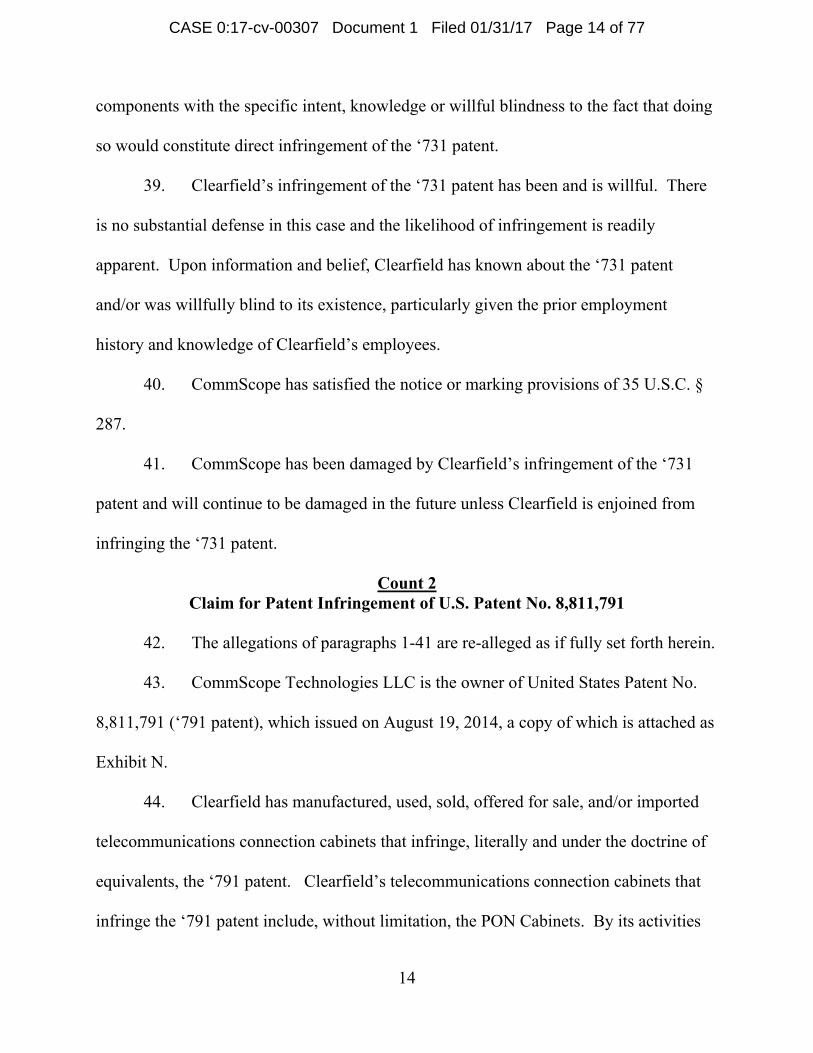
6. Each
, the optical
ng dust caps
shows a plu
6 having en
aphs below
A at pages
7. Each
for receivin
using, sellin
inets Clearf
‘791 patent
of the PON
g can be se
ucture surro
of the PON
l fibers hav
s” as recited
rality of op
nds connect
, the fiber o
7, 9, 11 and
of the PON
ng the fiber
ng, offering
field has in
t.
N Cabinets h
en, for exam
unding the
N Cabinets h
ving ends co
d in claim 1
ptical fibers
torized with
optic connec
d 13 include
N Cabinets h
r optic conn
15
g for sale, an
fringed and
has a “hous
mple, in Ex
component
has “a plura
onnectorized
of the ‘791
within the
h fiber optic
ctors in the
e dust caps:
has “a plura
nectors with
nd/or impor
d continues
sing” as rec
xhibit A at p
ts and cabli
ality of opti
d with fiber
1 patent. Ex
housing in
c connector
location id
:
ality of fibe
hout the dus
rting in or i
to infringe
ited in claim
pp. 7, 9, 11
ing.
ical fibers w
r optic conn
xhibit A at
the location
rs. As seen
dentified by
er optic adap
st caps on”
into the Uni
claim 1 and
m 1 of the ‘
and 13 as t
within the
nectors
pages 7, 9,
n identified
in the
y number 6 i
pters within
as recited in
ited
d
‘791
the
11
d by
in
n the
n
CASE 0:17-cv-00307 Document 1 Filed 01/31/17 Page 15 of 77
Page 16
claim 1
“Distribu
PON Ca
Ex. B at
p. 3 (“12
p. 2 (“lo
connecto
4
fiber opt
Exhibit A
“Parking
connecto
Clearfiel
shows th
storage p
of the ‘791
ution casset
abinets use c
p. 2 (“Clea
2 ports in a
oaded with S
ors without
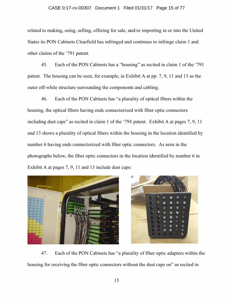
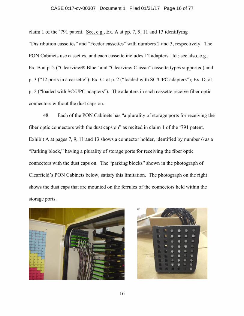
8. Each
tic connecto
A at pages
g block,” ha
ors with the
ld’s PON C
he dust caps
ports.
patent. Se
ttes” and “F
cassettes, an
arview® Bl
cassette”);
SC/UPC ad
the dust ca
of the PON
ors with the
7, 9, 11 and
aving a plur
e dust caps o
Cabinets bel
s that are m
e, e.g., Ex.
Feeder cass
nd each cas
lue” and “C
Ex. C. at p
dapters”). T
aps on.
N Cabinets h
e dust caps o
d 13 shows
rality of sto
on. The “p
low, satisfy
mounted on t
16
A at pp. 7,
ettes” with
ssette includ
Clearview C
. 2 (“loaded
The adapters
has “a plura
on” as recit
a connecto
orage ports f
parking bloc
y this limitat
the ferrules
9, 11 and 1
numbers 2
des 12 adap
Classic” cass
d with SC/U
s in each ca
ality of stor
ted in claim
or holder, id
for receivin
cks” shown
tion. The p
s of the conn
13 identifyin
and 3, resp
pters. Id.; s
sette types s
UPC adapte
assette recei
rage ports fo
m 1 of the ‘7
dentified by
ng the fiber
n in the phot
photograph
nectors held
ng
pectively. T
ee also, e.g
supported)
ers”); Ex. D
ive fiber op
or receiving
791 patent.
y number 6 a
optic
tograph of
on the righ
d within the
The
g.,
and
. at
ptic
g the
as a
ht
e
CASE 0:17-cv-00307 Document 1 Filed 01/31/17 Page 16 of 77
Page 17
17
See also Ex. A at p. 41 (“The input and output pigtails for the fiber splitter are stored and
accessed in the parking block located in the top corners of the cabinet.”).
49. Upon information and belief, Clearfield knew about or was willfully blind
to the existence of the ‘791 patent prior to service of this Complaint. At least as of
service of this Complaint, Clearfield has knowledge of the ‘791 patent.
50. Clearfield also indirectly infringes the ‘791 patent, including, for example,
and without limitation, claim 1 under 35 U.S.C. § 271(b) and (c). Customers of the PON
Cabinets having the Clearfield WaveSmart® Ruggedized Splitters and the Clearfield
Clearview® Blue or Classic cassettes installed therein directly infringe at least some
claims, including without limitation claim 1, of the ‘791 patent. Upon information and
belief, Clearfield knows its products are especially made or especially adapted for use in
an infringement. Clearfield knows its PON Cabinets are made to accommodate cassettes
having a plurality of adapters and splitters having pigtails terminating with connectors
and dust caps situated in a connector holder configured to fit within a storage area of the
PON Cabinets. See, e.g., Ex. A at p. 7 (“2. Distribution cassettes”, “3. Feeder cassettes”,
“5. Fiber splitter storage”, “6. Parking block”), p. 41 (“Install the splitter into the top-
most usable slot in the fiber storage bracket and lock into place using the splitter retainer
pin. . . . The input and output pigtails for the fiber splitter are stored and accessed in the
parking block located in the top corners of the cabinet.”); see also, e.g., Ex. B at p. 2
(“Clearview® Blue” and “Clearview Classic” cassette types supported).
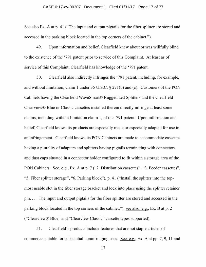
51. Clearfield’s products include features that are not staple articles of
commerce suitable for substantial noninfringing uses. See, e.g., Ex. A at pp. 7, 9, 11 and
CASE 0:17-cv-00307 Document 1 Filed 01/31/17 Page 17 of 77
Page 18
18
13. There is no substantial use for the structure defining the “parking block” region(s) in
the PON Cabinets other than to accommodate the plurality of storage ports for receiving
fiber optic connectors as recited in claim 1. The storage ports are defined in the foam
“parking blocks” of the Clearfield WaveSmart® Ruggedized Splitters. See, e.g., Ex. A at
pp. 7, 9, 11 and 13; Ex. E.
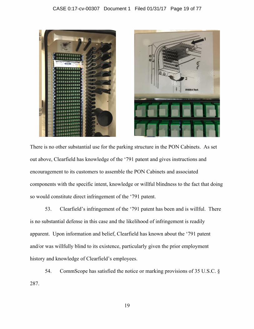
52. Clearfield has actively induced others, including its customers, to infringe
claims of the ‘791 patent, including but not limited to claim 1. For example, Clearfield
supplies product labels on its PON Cabinets and product literature for its PON Cabinets
and associated cassettes and splitters, examples of which are attached as Exhibits A-E,
that instruct and encourage its customers and users of its PON Cabinets to populate the
cabinets with the associated cassettes having adapters, splitters, connectors with dust
caps, and parking block assemblies in a manner that results in direct infringement of the
‘791 patent. For example, shown below is a product label attached to one of Clearfield’s
PON Cabinets that instructs a user to attach a parking block having stored connectors.
CASE 0:17-cv-00307 Document 1 Filed 01/31/17 Page 18 of 77
Page 19
There is
out abov
encourag
compon
so would
5
is no sub
apparent
and/or w
history a
5
287.
no other su
ve, Clearfie
gement to i
ents with th
d constitute
3. Clear
bstantial de
t. Upon inf
was willfully
and knowle
4. Comm
ubstantial u
ld has know
ts customer
he specific i
e direct infri
rfield’s infri
fense in thi
formation a
y blind to it
dge of Clea
mScope has
use for the p
wledge of th
rs to assemb
intent, know
ingement o
ingement o
s case and t
and belief, C
ts existence
arfield’s em
s satisfied th
19
parking stru
he ‘791 pate
ble the PON
wledge or w
f the ‘791 p
f the ‘791 p
the likeliho
Clearfield h
e, particular
mployees.
he notice or
ucture in the
ent and give
N Cabinets
willful blind
patent.
patent has b
ood of infrin
has known a
rly given the
r marking p
e PON Cabi
es instructio
and associa
dness to the
been and is w
ngement is r
about the ‘7
e prior emp
provisions o
inets. As se
ons and
ated
fact that do
willful. Th
readily
791 patent
ployment
of 35 U.S.C
et
oing
here
C. §
CASE 0:17-cv-00307 Document 1 Filed 01/31/17 Page 19 of 77
Page 20
20
55. CommScope has been damaged by Clearfield’s infringement of the ‘791
patent and will continue to be damaged in the future unless Clearfield is enjoined from
infringing the ‘791 patent.
Count 3 Claim for Patent Infringement of U.S. Patent No. 7,198,409
56. The allegations of paragraphs 1-55 are re-alleged as if fully set forth herein.
57. CommScope Technologies LLC is the owner of United States Patent No.
7,198,409 (‘409 patent), which issued on April 3, 2007, a copy of which is attached as
Exhibit O.
58. Clearfield has manufactured, used, sold, offered for sale, and/or imported
telecommunications products that infringe, literally and under the doctrine of equivalents,
the ‘409 patent. Clearfield’s telecommunications products that infringe the ‘409 patent
include, without limitation, the Clearfield WaveSmart® Ruggedized Splitters. By its
activities related to making, using, selling, offering for sale, and/or importing in or into
the United States the WaveSmart® Ruggedized Splitters Clearfield has infringed and
continues to infringe claim 26 and other claims of the ‘409 patent.
59. The WaveSmart® Ruggedized Splitters have “a fiber optic connector
including a connector body having a first and a second end, the fiber optic connector also
including a ferrule positioned at the first end of the connector body, the ferrule having a
side surface and an end surface, the ferrule holding an optical fiber having a polished end
face positioned at the end surface of the ferrule” as recited in claim 26 of the ‘409 patent.
CASE 0:17-cv-00307 Document 1 Filed 01/31/17 Page 20 of 77
Page 21
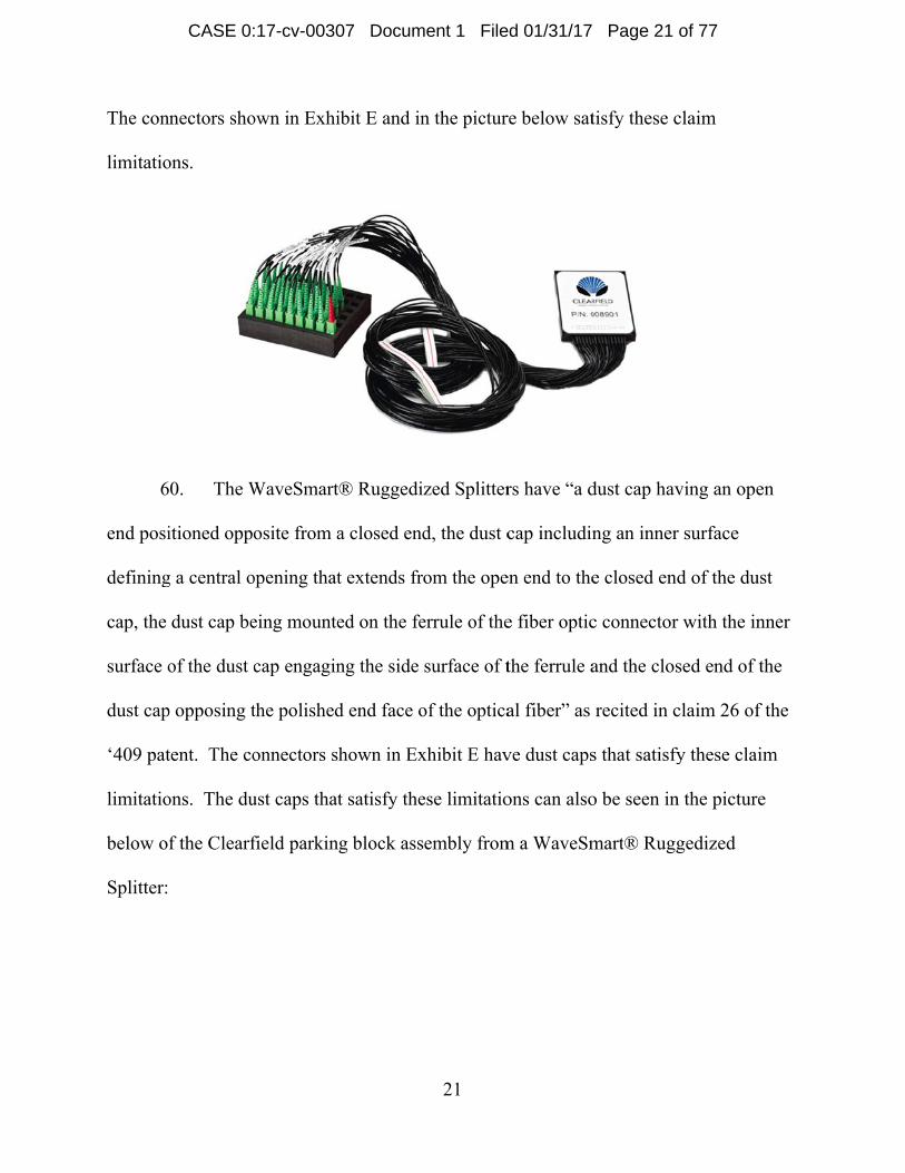
The con
limitatio
6
end posi
defining
cap, the
surface o
dust cap
‘409 pat
limitatio
below of
Splitter:
nectors sho
ons.
0. The W
itioned oppo
g a central o
dust cap be
of the dust c
p opposing t
tent. The co
ons. The du
f the Clearf
own in Exhi
WaveSmart
osite from a
opening that
eing mounte
cap engagin
the polished
onnectors sh
ust caps that
field parkin
ibit E and in
® Ruggedi
a closed end
t extends fr
ed on the fe
ng the side
d end face o
hown in Ex
t satisfy the
g block ass
21
n the pictur
zed Splitter
d, the dust c
om the ope
errule of the
surface of t
of the optica
xhibit E hav
ese limitatio
embly from
re below sat
rs have “a d
cap includin
en end to the
e fiber optic
the ferrule a
al fiber” as
ve dust caps
ons can also
m a WaveSm
tisfy these c
dust cap hav
ng an inner
e closed end
c connector
and the clos
recited in c
s that satisfy
o be seen in
mart® Rugg
claim
ving an ope
r surface
d of the dus
r with the in
sed end of t
claim 26 of
fy these clai
n the picture
gedized
en
st
nner
the
f the
im
e
CASE 0:17-cv-00307 Document 1 Filed 01/31/17 Page 21 of 77
Page 22
6
holding
ferrule, t
being siz
side of th
the fiber
blocks a
holder”
photogra
satisfy th
in a cabi
photogra
connecto
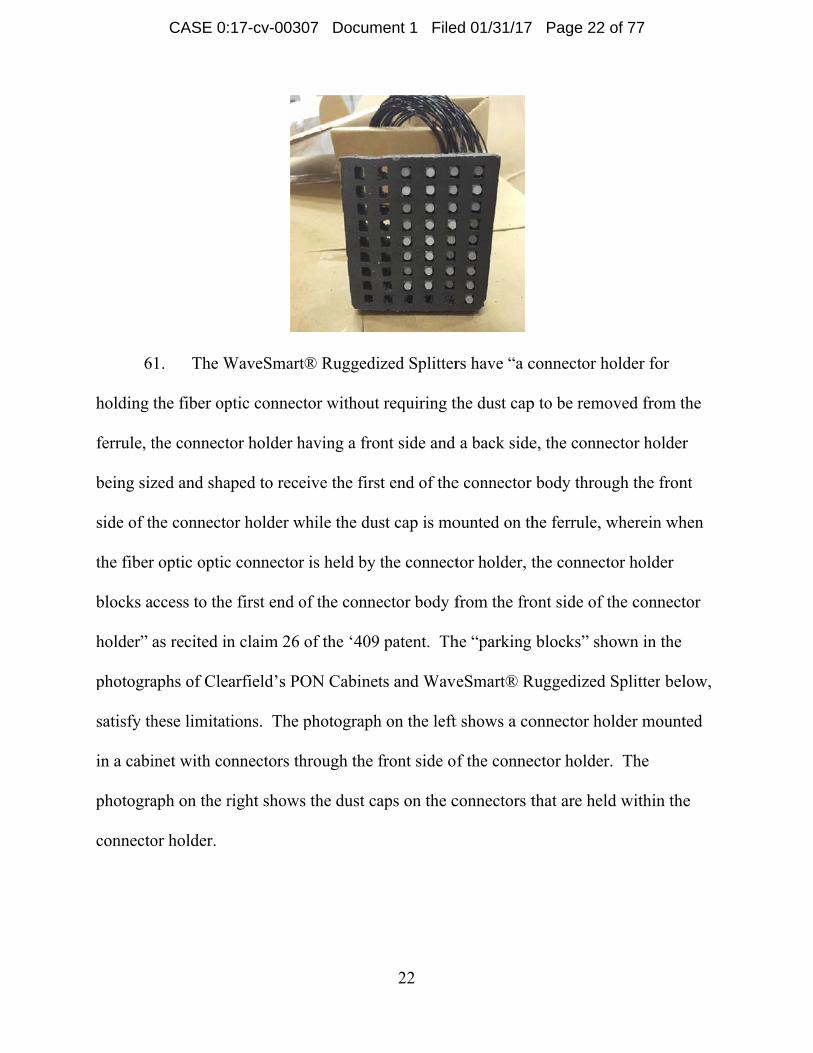
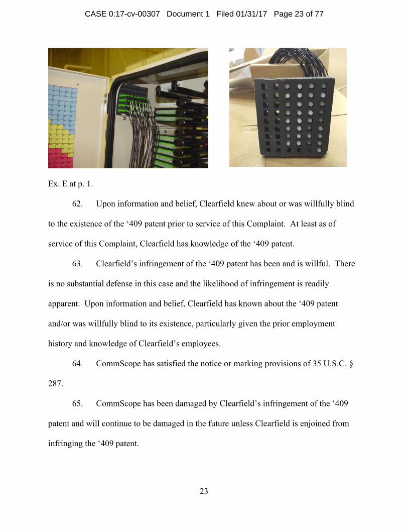
1. The W
the fiber op
the connect
zed and sha
he connecto
r optic optic
access to the
as recited in
aphs of Cle
hese limitat
inet with co
aph on the r
or holder.
WaveSmart
ptic connect
tor holder h
aped to rece
or holder w
c connector
e first end o
n claim 26
arfield’s PO
tions. The p
onnectors th
right shows
® Ruggedi
tor without
having a fro
eive the firs
while the dus
is held by t
of the conne
of the ‘409
ON Cabinet
photograph
hrough the f
s the dust ca
22
zed Splitter
requiring th
nt side and
t end of the
st cap is mo
the connect
ector body f
patent. Th
ts and Wav
h on the left
front side o
aps on the c
rs have “a c
the dust cap
a back side
e connector
ounted on th
tor holder, t
from the fro
he “parking
eSmart® R
t shows a co
f the conne
connectors t
connector h
p to be remo
e, the conne
body throu
he ferrule, w
the connect
ont side of t
blocks” sh
Ruggedized
onnector ho
ector holder
that are held
holder for
oved from t
ector holder
ugh the fron
wherein wh
tor holder
the connect
hown in the
Splitter bel
older mount
r. The
d within the
the
r
nt
hen
tor
low,
ted
e
CASE 0:17-cv-00307 Document 1 Filed 01/31/17 Page 22 of 77
Page 23
Ex. E at
6
to the ex
service o
6
is no sub
apparent
and/or w
history a
6
287.
6
patent an
infringin
p. 1.
2. Upon
xistence of t
of this Com
3. Clear
bstantial de
t. Upon inf
was willfully
and knowle
4. Comm
5. Comm
nd will cont
ng the ‘409
n informatio
the ‘409 pa
mplaint, Clea
rfield’s infri
fense in thi
formation a
y blind to it
dge of Clea
mScope has
mScope has
tinue to be
patent.
on and belie
tent prior to
arfield has k
ingement o
s case and t
and belief, C
ts existence
arfield’s em
s satisfied th
s been dama
damaged in
23
ef, Clearfiel
o service of
knowledge
f the ‘409 p
the likeliho
Clearfield h
e, particular
mployees.
he notice or
aged by Cle
n the future
ld knew abo
f this Comp
of the ‘409
patent has b
ood of infrin
has known a
rly given the
r marking p
earfield’s in
unless Cle
out or was w
plaint. At le
9 patent.
been and is w
ngement is r
about the ‘4
e prior emp
provisions o
nfringemen
arfield is en
willfully bli
east as of
willful. Th
readily
409 patent
ployment
of 35 U.S.C
nt of the ‘40
njoined from
ind
here
C. §
09
m
CASE 0:17-cv-00307 Document 1 Filed 01/31/17 Page 23 of 77
Page 24
6
6
7,809,23
Exhibit P
6
telecomm
the ‘233
include,
activitie
the Unit
continue
6
in claim
picture i
Claim
6. The a
7. Comm
33 (‘233 pat
P.
8. Clear
munication
patent. C
without lim
s related to
ed States th
es to infring
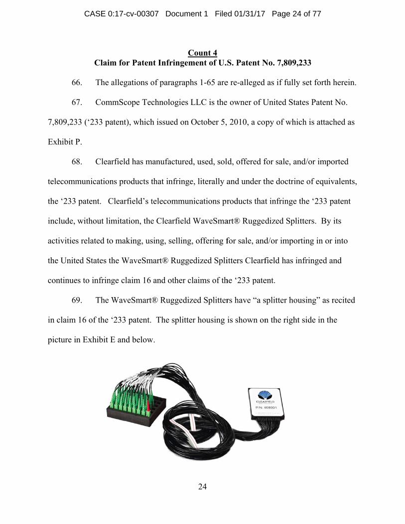
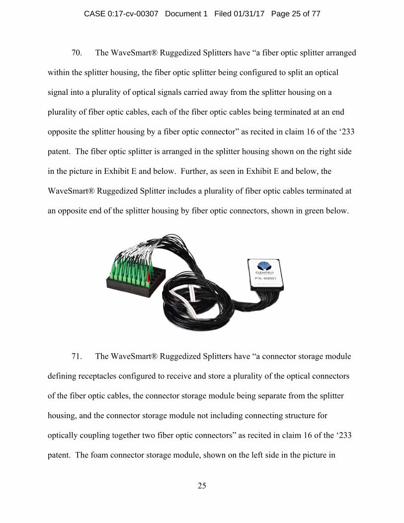
9. The W
16 of the ‘
in Exhibit E
m for Paten
allegations o
mScope Tec
tent), which
rfield has m
s products t
learfield’s t
mitation, the
making, us
he WaveSm
ge claim 16
WaveSmart
233 patent.
E and below
Cnt Infringem
of paragrap
chnologies
h issued on
manufactured
that infring
telecommun
e Clearfield
sing, selling
mart® Rugg
and other c
® Ruggedi
The splitte
w.
24
Count 4 ment of U.S
hs 1-65 are
LLC is the
October 5,
d, used, sol
e, literally a
nications pr
d WaveSma
g, offering f
edized Spli
claims of th
zed Splitter
er housing i
S. Patent N
e re-alleged
owner of U
2010, a co
ld, offered f
and under t
roducts that
art® Rugged
for sale, and
itters Clearf
he ‘233 pate
rs have “a s
is shown on
No. 7,809,23
as if fully s
United State
py of which
for sale, and
the doctrine
t infringe th
dized Splitt
d/or import
field has inf
ent.
splitter hous
n the right s
33
set forth he
es Patent N
h is attache
d/or importe
e of equival
he ‘233 pate
ters. By its
ing in or in
fringed and
sing” as rec
side in the
rein.
No.
d as
ed
ents,
ent
s
nto
d
cited
CASE 0:17-cv-00307 Document 1 Filed 01/31/17 Page 24 of 77
Page 25
7
within th
signal in
plurality
opposite
patent. T
in the pi
WaveSm
an oppos
7
defining
of the fib
housing,
optically
patent. T
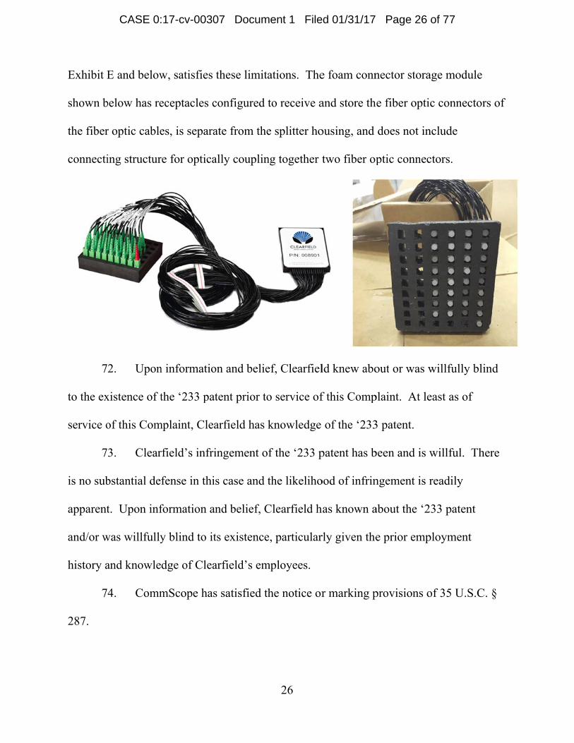
0. The W
he splitter h
nto a plurali
y of fiber op
e the splitter
The fiber op
cture in Ex
mart® Rugg
site end of t
1. The W
g receptacle
ber optic ca
, and the co
y coupling t
The foam c
WaveSmart
housing, the
ity of optica
ptic cables,
r housing by
ptic splitter
hibit E and
gedized Spl
the splitter
WaveSmart
s configure
ables, the co
onnector sto
together two
connector st
® Ruggedi
e fiber optic
al signals ca
each of the
y a fiber op
r is arranged
below. Fu
litter includ
housing by
® Ruggedi
ed to receive
onnector sto
orage modu
o fiber opti
torage modu
25
zed Splitter
c splitter bei
arried away
fiber optic
ptic connect
d in the spli
urther, as se
es a pluralit
y fiber optic
zed Splitter
e and store
orage modu
le not inclu
c connector
ule, shown
rs have “a f
ing configu
y from the s
c cables bein
tor” as recit
itter housin
en in Exhib
ty of fiber o
c connectors
rs have “a c
a plurality
ule being se
uding conne
rs” as recite
on the left
fiber optic s
ured to split
splitter hous
ng terminat
ted in claim
ng shown on
bit E and be
optic cables
s, shown in
connector st
of the optic
eparate from
ecting struct
ed in claim
side in the
splitter arran
t an optical
sing on a
ted at an en
m 16 of the ‘
n the right s
elow, the
s terminated
n green belo
torage mod
cal connecto
m the splitte
ture for
16 of the ‘2
picture in
nged
d
‘233
side
d at
ow.
dule
ors
er
233
CASE 0:17-cv-00307 Document 1 Filed 01/31/17 Page 25 of 77
Page 26
Exhibit E
shown b
the fiber
connecti
7
to the ex
service o
7
is no sub
apparent
and/or w
history a
7
287.
E and below
below has re
r optic cable
ing structur
2. Upon
xistence of t
of this Com
3. Clear
bstantial de
t. Upon inf
was willfully
and knowle
4. Comm
w, satisfies
eceptacles c
es, is separa
re for optica
n informatio
the ‘233 pa
mplaint, Clea
rfield’s infri
fense in thi
formation a
y blind to it
dge of Clea
mScope has
these limita
configured t
ate from the
ally couplin
on and belie
tent prior to
arfield has k
ingement o
s case and t
and belief, C
ts existence
arfield’s em
s satisfied th
26
ations. The
to receive a
e splitter ho
ng together t
ef, Clearfiel
o service of
knowledge
f the ‘233 p
the likeliho
Clearfield h
e, particular
mployees.
he notice or
e foam conn
and store th
ousing, and
two fiber op
ld knew abo
f this Comp
of the ‘233
patent has b
ood of infrin
has known a
rly given the
r marking p
nector stora
he fiber opti
does not in
ptic connec
out or was w
plaint. At le
3 patent.
been and is w
ngement is r
about the ‘2
e prior emp
provisions o
age module
c connector
nclude
ctors.
willfully bli
east as of
willful. Th
readily
233 patent
ployment
of 35 U.S.C
rs of
ind
here
C. §
CASE 0:17-cv-00307 Document 1 Filed 01/31/17 Page 26 of 77
Page 27
27
75. CommScope has been damaged by Clearfield’s infringement of the ‘233
patent and will continue to be damaged in the future unless Clearfield is enjoined from
infringing the ‘233 patent.
Count 5 Claim for Patent Infringement of U.S. Patent No. 9,201,206
76. The allegations of paragraphs 1-75 are re-alleged as if fully set forth herein.
77. CommScope Technologies LLC is the owner of United States Patent No.
9,201,206 (‘206 patent), which issued on December 1, 2015, a copy of which is attached
as Exhibit Q.
78. Clearfield has manufactured, used, sold, offered for sale, and/or imported
telecommunications products that infringe, literally and under the doctrine of equivalents,
the ‘206 patent. Clearfield’s telecommunications products that infringe the ‘206 patent
include, without limitation, the Clearfield WaveSmart® Ruggedized Splitters. By its
activities related to making, using, selling, offering for sale, and/or importing in or into
the United States the WaveSmart® Ruggedized Splitters Clearfield has infringed and
continues to infringe claim 1 and other claims of the ‘206 patent.
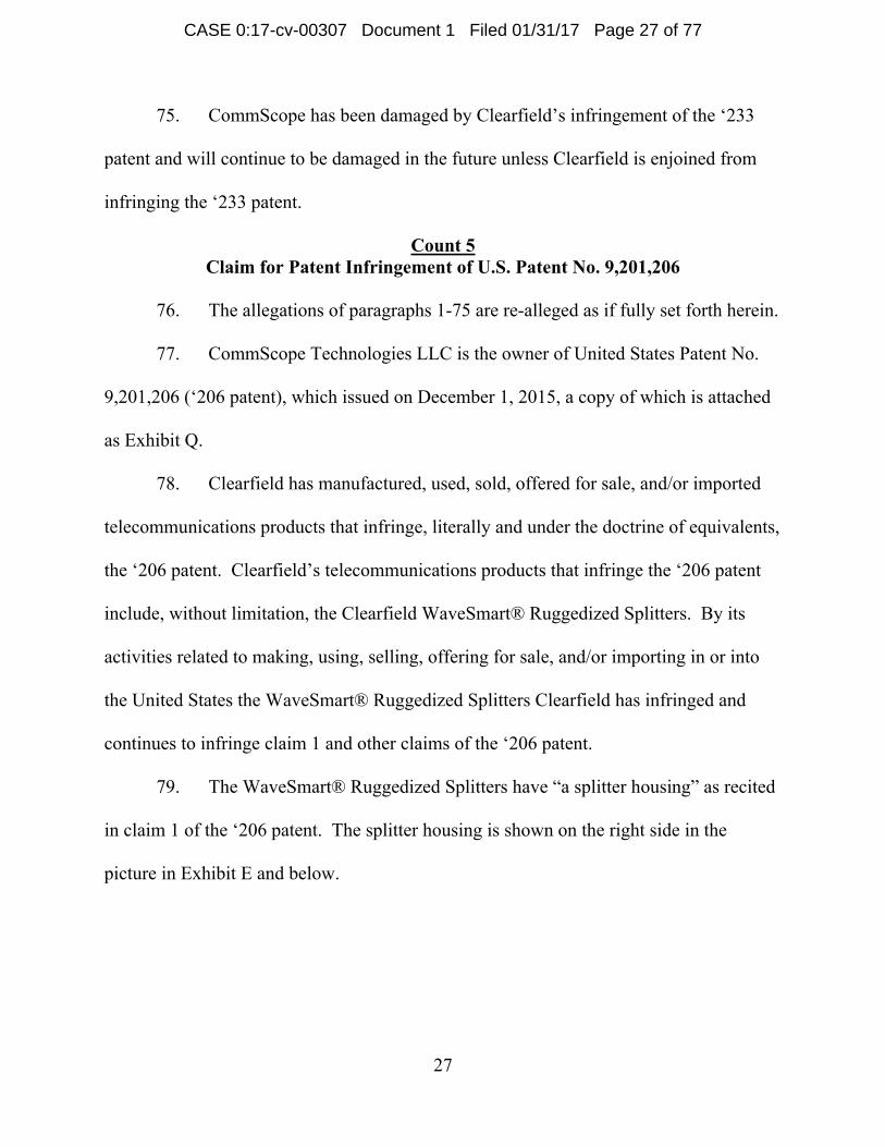
79. The WaveSmart® Ruggedized Splitters have “a splitter housing” as recited
in claim 1 of the ‘206 patent. The splitter housing is shown on the right side in the
picture in Exhibit E and below.
CASE 0:17-cv-00307 Document 1 Filed 01/31/17 Page 27 of 77
Page 28
8
within th
signal in
plurality
opposite
splitter i
E and be
Splitter i
splitter h
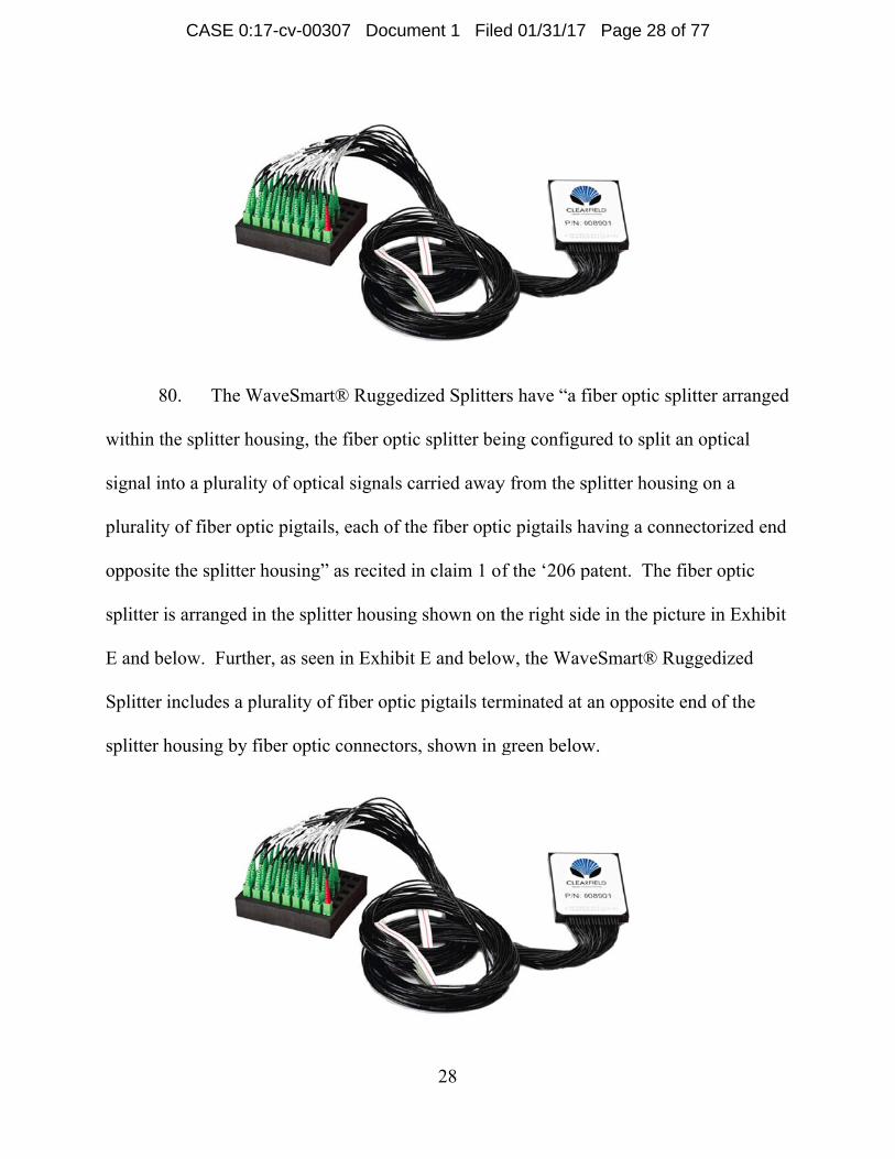
0. The W
he splitter h
nto a plurali
y of fiber op
e the splitter
is arranged
elow. Furth
includes a p
housing by
WaveSmart
housing, the
ity of optica
ptic pigtails
r housing” a
in the splitt
her, as seen
plurality of
fiber optic
® Ruggedi
e fiber optic
al signals ca
, each of th
as recited in
ter housing
in Exhibit
fiber optic
connectors
28
zed Splitter
c splitter bei
arried away
he fiber opti
n claim 1 of
shown on t
E and below
pigtails term
, shown in g
rs have “a f
ing configu
y from the s
ic pigtails h
f the ‘206 p
the right sid
w, the Wav
minated at
green below
fiber optic s
ured to split
splitter hous
having a con
patent. The
de in the pic
veSmart® R
an opposite
w.
splitter arran
t an optical
sing on a
nnectorized
e fiber optic
cture in Exh
Ruggedized
e end of the
nged
d end
c
hibit
e
CASE 0:17-cv-00307 Document 1 Filed 01/31/17 Page 28 of 77
Page 29
8
to store
module b
connecti
claim 1
picture i
shown b
optic pig
structure
8
to the ex
service o
8
is no sub
apparent
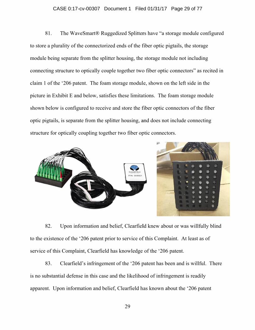
1. The W
a plurality o
being separ
ing structur
of the ‘206
in Exhibit E
below is con
gtails, is sep
e for optical
2. Upon
xistence of t
of this Com
3. Clear
bstantial de
t. Upon inf
WaveSmart
of the conn
rate from th
re to optical
patent. Th
E and below
nfigured to
parate from
lly coupling
n informatio
the ‘206 pa
mplaint, Clea
rfield’s infri
fense in thi
formation a
® Ruggedi
ectorized en
he splitter h
lly couple to
he foam stor
w, satisfies t
receive and
m the splitter
g together t
on and belie
tent prior to
arfield has k
ingement o
s case and t
and belief, C
29
zed Splitter
nds of the f
ousing, the
ogether two
rage modul
these limitat
d store the f
r housing, a
two fiber op
ef, Clearfiel
o service of
knowledge
f the ‘206 p
the likeliho
Clearfield h
rs have “a s
fiber optic p
storage mo
o fiber optic
le, shown on
ations. The
fiber optic c
and does no
ptic connect
ld knew abo
f this Comp
of the ‘206
patent has b
ood of infrin
has known a
storage mod
pigtails, the
odule not in
c connector
n the left si
foam stora
connectors o
ot include co
tors.
out or was w
plaint. At le
6 patent.
been and is w
ngement is r
about the ‘2
dule configu
e storage
ncluding
rs” as recite
de in the
ge module
of the fiber
onnecting
willfully bli
east as of
willful. Th
readily
206 patent
ured
ed in
ind
here
CASE 0:17-cv-00307 Document 1 Filed 01/31/17 Page 29 of 77
Page 30
30
and/or was willfully blind to its existence, particularly given the prior employment
history and knowledge of Clearfield’s employees.
84. CommScope has satisfied the notice or marking provisions of 35 U.S.C. §
287.
85. CommScope has been damaged by Clearfield’s infringement of the ‘206
patent and will continue to be damaged in the future unless Clearfield is enjoined from
infringing the ‘206 patent.
Count 6 Claim for Patent Infringement of U.S. Patent No. 7,809,234
86. The allegations of paragraphs 1-85 are re-alleged as if fully set forth herein.
87. CommScope Technologies LLC is the owner of United States Patent No.
7,809,234 (‘234 patent), which issued on October 5, 2010, a copy of which is attached as
Exhibit R.
88. Clearfield has manufactured, used, sold, offered for sale, and/or imported
telecommunications connection cabinets that infringe, literally and under the doctrine of
equivalents, the ‘234 patent. Clearfield’s telecommunications connection cabinets that
infringe the ‘234 patent include, without limitation, the PON Cabinets. By its activities
related to making, using, selling, offering for sale, and/or importing in or into the United
States its PON Cabinets Clearfield has infringed and continues to infringe claim 8 and
other claims of the ‘234 patent.
89. Each of the PON Cabinets has “an enclosure defining an interior, the
enclosure including a door for at least partially covering an opening used to access the
CASE 0:17-cv-00307 Document 1 Filed 01/31/17 Page 30 of 77
Page 31
31
interior” as recited in claim 8 of the ‘234 patent. The enclosure and door can be seen, for
example, in Exhibit A at pp. 7, 9, 11 and 13 as the outer off-white structure surrounding
the components and cabling.
90. Each of the PON Cabinets has “a fiber optic splitter module mounting
location positioned within the interior of the enclosure and accessible from the enclosure
opening” as recited in claim 8 of the ‘234 patent. The fiber optic splitter module
mounting location can be seen, for example, in Exhibit A at pp. 7, 9, 11 and 13 in the
location identified by number 5.
91. Each of the PON Cabinets has “a fiber connection location positioned
within the interior of the enclosure, the fiber connection location including a plurality of
fiber optic adapters, each fiber optic adapter being configured for coupling together two
fiber optic connectors such that an optical interconnection is made between the two fiber
optic connectors” as recited in claim 8 of the ‘234 patent. See, e.g., Ex. A at pp. 7, 9, 11
and 13 identifying “Distribution cassettes” and “Feeder cassettes” with numbers 2 and 3,
respectively. The PON Cabinets use cassettes, and each cassette includes 12 adapters.
Id.; see also, e.g., Ex. B at p. 2 (“Clearview® Blue” and “Clearview Classic” cassette
types supported) and p. 3 (“12 ports in a cassette”); Ex. C. at p. 2 (“loaded with SC/UPC
adapters”); Ex. D. at p. 2 (“loaded with SC/UPC adapters”).
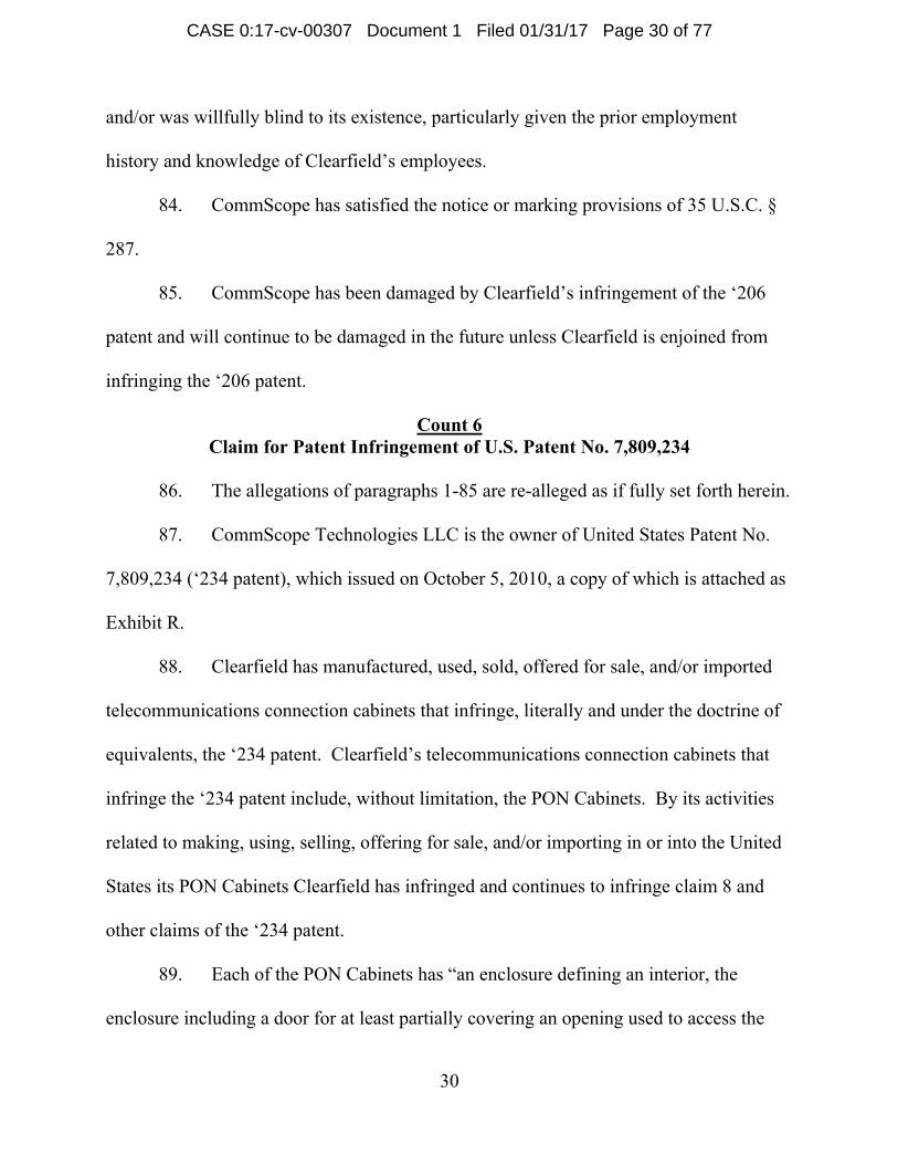
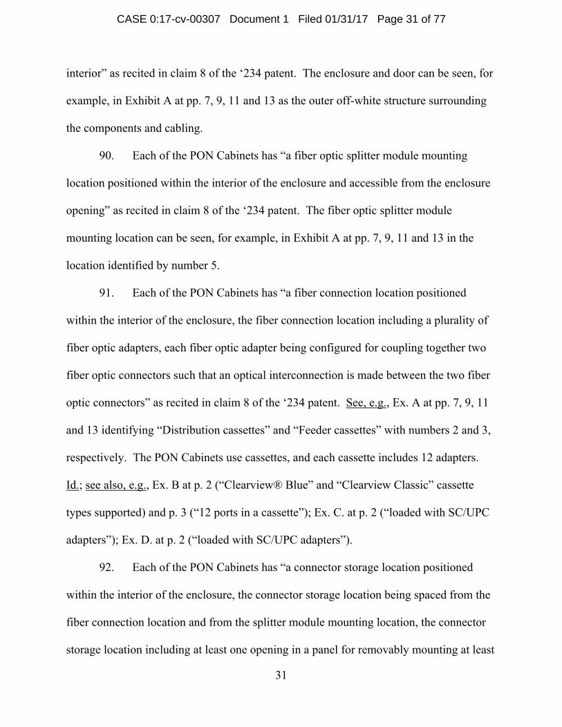
92. Each of the PON Cabinets has “a connector storage location positioned
within the interior of the enclosure, the connector storage location being spaced from the
fiber connection location and from the splitter module mounting location, the connector
storage location including at least one opening in a panel for removably mounting at least
CASE 0:17-cv-00307 Document 1 Filed 01/31/17 Page 31 of 77
Page 32
one mul
claim 8
location
“Parking
the fiber
module
cabinets
panel fo
the left s
holder, a
mounted
See, e.g.
pigtails f
top corn
ti-connecto
of the ‘234
which incl
g block,” po
r connection
mounting lo
, shown for
r removably
shows the p
and the pho
d using the
., Ex. A at p
for the fiber
ners of the c
or connector
patent. Ex
udes a mult
ositioned w
n locations,
ocation, ide
r example in
y mounting
panel with a
otograph on
opening in
pp. 7, 9, 11
r splitter are
cabinet.”).
r holder at t
xhibit A at p
ti-connecto
within the int
identified b
entified by n
n the pictur
g the multi-c
an opening f
the right sh
the panel.
and 13; see
e stored and
32
the connect
pages 7, 9, 1
r connector
terior of the
by numbers
number 5.
res below, in
connector c
for mountin
hows the m
e also Ex. A
d accessed
tor storage l
11 and 13 s
r holder, ide
e enclosure
s 2 and 3, a
The storage
ncludes at l
connector h
ng the multi
multi-connec
A at p. 41 (“
in the parki
location” as
shows a con
entified by
and being
and from the
e location o
least one op
holder. The
i-connector
ctor connect
“The input a
ing block lo
s recited in
nnector stor
number 6 a
spaced from
e splitter
of the PON
pening in a
photograph
r connector
tor holder
and output
ocated in th
rage
as a
m
h on
he
CASE 0:17-cv-00307 Document 1 Filed 01/31/17 Page 32 of 77
Page 33
33
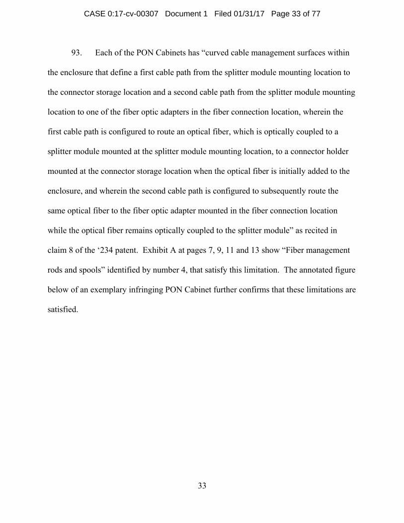
93. Each of the PON Cabinets has “curved cable management surfaces within
the enclosure that define a first cable path from the splitter module mounting location to
the connector storage location and a second cable path from the splitter module mounting
location to one of the fiber optic adapters in the fiber connection location, wherein the
first cable path is configured to route an optical fiber, which is optically coupled to a
splitter module mounted at the splitter module mounting location, to a connector holder
mounted at the connector storage location when the optical fiber is initially added to the
enclosure, and wherein the second cable path is configured to subsequently route the
same optical fiber to the fiber optic adapter mounted in the fiber connection location
while the optical fiber remains optically coupled to the splitter module” as recited in
claim 8 of the ‘234 patent. Exhibit A at pages 7, 9, 11 and 13 show “Fiber management
rods and spools” identified by number 4, that satisfy this limitation. The annotated figure
below of an exemplary infringing PON Cabinet further confirms that these limitations are
satisfied.
CASE 0:17-cv-00307 Document 1 Filed 01/31/17 Page 33 of 77
Page 34
See, e.g.
9
to the ex
service o
9
and with
Cabinets
directly
patent. U
or espec
made to
., Ex. A at p
4. Upon
xistence of t
of this Com
5. Clear
hout limitati
s having the
infringe at
Upon inform
cially adapte
accommod
p. 7; see als
n informatio
the ‘234 pa
mplaint, Clea
rfield also in
ion, claim 8
e Clearfield
least some
mation and
ed for use in
date cassette
so, e.g., Ex.
on and belie
tent prior to
arfield has k
ndirectly in
8 under 35 U
d Clearview
claims, inc
d belief, Cle
n an infring
es having a
34
A at pp. 9,
ef, Clearfiel
o service of
knowledge
nfringes the
U.S.C. § 27
w® Blue or C
luding with
arfield know
gement. Cle
plurality of
11 and 13.
ld knew abo
f this Comp
of the ‘234
‘234 paten
71(b) and (c
Classic cas
hout limitati
ws its prod
earfield kno
f adapters,
.
out or was w
plaint. At le
4 patent.
nt, including
c). Custom
settes instal
ion claim 8
ducts are esp
ows its PON
and that the
Cu
m
su
willfully bli
east as of
g, for examp
mers of the P
lled therein
8, of the ‘23
pecially ma
N Cabinets
e fiber
urved cable
management
urfaces
ind
ple,
PON
n
4
ade
are
CASE 0:17-cv-00307 Document 1 Filed 01/31/17 Page 34 of 77
Page 35
35
management spools define optical fiber pathways as described in the ‘234 patent. See,
e.g., Ex. A at p. 7 (“2. Distribution cassettes”, “3. Feeder cassettes”, “5. Fiber splitter
storage”, “6. Parking block”), p. 41 (“Install the splitter into the top-most usable slot in
the fiber storage bracket and lock into place using the splitter retainer pin. Route the
fibers from the splitter over to and around the right side of the D-spool in the lower right
side of the cabinet. Then route the fibers to the top-most radius spool in the upper right
side of the cabinet, loop the fibers over the radius limiter and across the two support
fingers. Install the parking block into the parking block brackets located in the top
corners of the cabinet. . . . The input and output pigtails for the fiber splitter are stored
and accessed in the parking block located in the top corners of the cabinet. Route the
input pigtail to the feeder port . . . Route the output pigtails to the distribution ports.”);
see also, e.g., Ex. B at p. 2 (“Clearview® Blue” and “Clearview Classic” cassette types
supported).
96. Clearfield’s products include features that are not staple articles of
commerce suitable for substantial noninfringing uses. For example, there is no
substantial use for the cassette positions in the PON Cabinets other than to accommodate
cassettes having adapters, including for example the Clearfield Clearview® Blue and
Clearview® Classic cassettes. See, e.g., Ex. A at pp. 7, 9, 11 and 13; Exs. C-D.
97. Clearfield has actively induced others, including its customers, to infringe
claims of the ‘234 patent, including but not limited to claim 8. For example, Clearfield’s
product literature for its PON Cabinets and associated cassettes, examples of which are
attached as Exhibits A-D, instructs and encourages its customers and users of its PON
CASE 0:17-cv-00307 Document 1 Filed 01/31/17 Page 35 of 77
Page 36
36
Cabinets to populate the cabinets with the associated cassettes having adapters, as well as
splitters, optical fibers, connectors, and parking block assemblies in a manner that results
in direct infringement of the ‘234 patent. There is no other substantial use for the cassette
positions in the PON Cabinets. As set out above, Clearfield has knowledge of the ‘234
patent and gives instructions and encouragement to its customers to assemble the PON
Cabinets and associated components with the specific intent, knowledge or willful
blindness to the fact that doing so would constitute direct infringement of the ‘234 patent.
98. Clearfield’s infringement of the ‘234 patent has been and is willful. There
is no substantial defense in this case and the likelihood of infringement is readily
apparent. Upon information and belief, Clearfield has known about the ‘234 patent
and/or was willfully blind to its existence, particularly given the prior employment
history and knowledge of Clearfield’s employees.
99. CommScope has satisfied the notice or marking provisions of 35 U.S.C. §
287.
100. CommScope has been damaged by Clearfield’s infringement of the ‘234
patent and will continue to be damaged in the future unless Clearfield is enjoined from
infringing the ‘234 patent.
Count 7 Claim for Patent Infringement of U.S. Patent No. 7,816,602
101. The allegations of paragraphs 1-100 are re-alleged as if fully set forth
herein.
CASE 0:17-cv-00307 Document 1 Filed 01/31/17 Page 36 of 77
Page 37
37
102. CommScope Technologies LLC is the owner of United States Patent No.
7,816,602 (‘602 patent), which issued on October 19, 2010, a copy of which is attached
as Exhibit S.
103. Clearfield has manufactured, used, sold, offered for sale, and/or imported
telecommunications connection cabinets that infringe, literally and under the doctrine of
equivalents, the ‘602 patent. Clearfield’s telecommunications connection cabinets that
infringe the ‘602 patent include, without limitation, the PON Cabinets having the Ground
Locate Box option. By its activities related to making, using, selling, offering for sale,
and/or importing in or into the United States its PON Cabinets having the Ground Locate
Box option Clearfield has infringed and continues to infringe at least claim 11 of the ‘602
patent.
104. Each of the PON Cabinets having the Ground Locate Box option has “a
cabinet defining a primary compartment, the cabinet also including one or more main
doors for accessing the primary compartment” as recited in claim 11 of the ‘602 patent.
The cabinet can be seen, for example, in Exhibit A at pp. 7, 9, 11 and 13 as the outer off-
white structure surrounding the components and cabling. The cabinet defines a primary
compartment and includes at least one door for accessing the primary compartment. See,
e.g., Ex. A at pp. 7, 9, 11 and 13.
105. Each of the PON Cabinets having the Ground Locate Box option has
“telecommunications equipment mounted within the primary compartment” as recited in
claim 11 of the ‘602 patent. See, e.g., Ex. A at pp. 7, 9, 11 and 13 identifying
“Distribution cassettes” and “Feeder cassettes” with numbers 2 and 3, respectively. The
CASE 0:17-cv-00307 Document 1 Filed 01/31/17 Page 37 of 77
Page 38
PON Ca
Ex. B at
p. 3 (“12
p. 2 (“lo
1
secondar
accessin
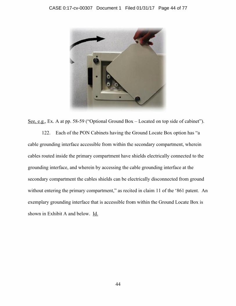
at page 2
exempla
See, e.g.
1
groundin
groundin
plate, th
abinets use c
p. 2 (“Clea
2 ports in a
oaded with S
06. Each
ry compartm
ng the prima
21 identifie
ary Ground
., Ex. A at p
07. Each
ng interface
ng interface
e posts bein
cassettes, an
arview® Bl
cassette”);
SC/UPC ad
of the PON
ment that ca
ary compart
s the “Grou
Locate Box
pp. 58-59 (“
of the PON
e accessible
e comprises
ng electrica
nd each cas
lue” and “C
Ex. C. at p
dapters”).
N Cabinets h
an be acces
tment” as re
und Locate
x is shown
“Optional G
N Cabinets h
e from withi
s a bus plate
ally connect
38
ssette includ
Clearview C
. 2 (“loaded
having the G
ssed from an
ecited in cla
Box” as op
in Exhibit A
Ground Box
having the G
in the secon
e and a plur
ted to the bu
des 12 adap
Classic” cass
d with SC/U
Ground Loc
n exterior o
aim 11 of th
ptional on th
A and below
x – Located
Ground Loc
ndary comp
rality of pos
us plate,” as
pters. Id.; s
sette types s
UPC adapte
cate Box op
of the cabin
he ‘602 pat
he PON Cab
w.
d on top side
cate Box op
partment; w
sts protrudin
s recited in
ee also, e.g
supported)
ers”); Ex. D
ption has “a
net without
ent. Exhibi
binets. An
e of cabinet
ption has “a
wherein the
ng from the
claim 11 o
g.,
and
. at
a
it A
t”).
a
e bus
f the
CASE 0:17-cv-00307 Document 1 Filed 01/31/17 Page 38 of 77
Page 39
‘602 pat
Locate B
Exhibit A
plate, an
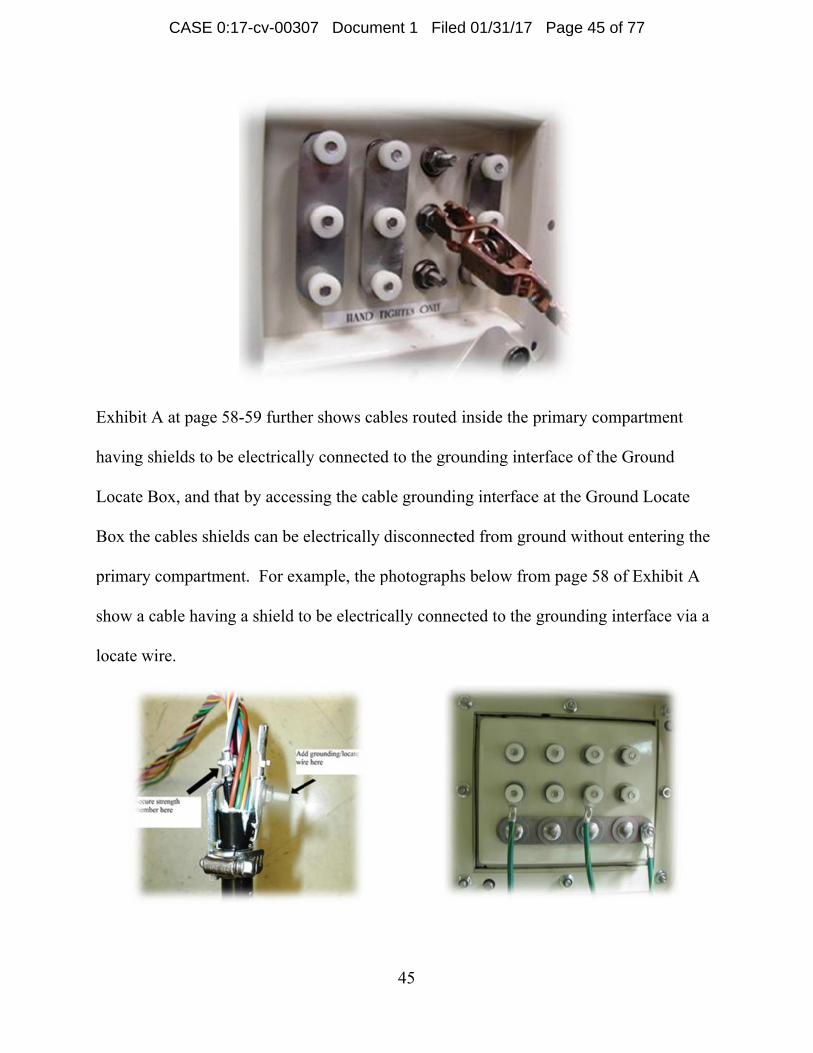
1
having t
thus sati
e.g., Ex.
“Connec
cabinet.”
1
to the ex
service o
tent. An ex
Box is show
A and below
nd the posts
08. Upon
he Ground
isfying the l
A at p. 58
ct the comm
”).
09. Upon
xistence of t
of this Com
xemplary gr
wn in Exhib
w includes
are electric
n informatio
Locate Box
limitation “
(“Optional
mon ground
n informatio
the ‘602 pa
mplaint, Clea
ounding int
it A and be
a bus plate
cally conne
on and belie
x option, ele
“the bus plat
Ground Bo
ding stud to
on and belie
tent prior to
arfield has k
39
terface that
low. Id. T
and a plura
cted to the
ef, Clearfiel
ectrically co
te being ele
ox – Locate
the earth gr
ef, Clearfiel
o service of
knowledge
is accessib
The groundi
ality of post
bus plate. I
ld has, for e
onnected th
ectrically co
ed on top sid
round that y
ld knew abo
f this Comp
of the ‘602
ble from wit
ing interface
ts protrudin
Id.
each of the P
he bus plate
onnected to
de of cabin
you will be
out or was w
plaint. At le
2 patent.
thin the Gro
e shown in
ng from the
PON Cabin
e to ground,
o ground.” S
et” . . .
using for th
willfully bli
east as of
ound
bus
nets
,
See,
he
ind
CASE 0:17-cv-00307 Document 1 Filed 01/31/17 Page 39 of 77
Page 40
40
110. Clearfield also indirectly infringes the ‘602 patent, including at least claim
11 under 35 U.S.C. § 271(b) and (c). Customers of the PON Cabinets having the Ground
Locate Box option electrically connect the bus plate to ground, thereby directly infringing
at least claim 11 of the ‘602 patent. Upon information and belief, Clearfield knows its
products are especially made or especially adapted for use in an infringement. Clearfield
knows its PON Cabinets are made to accommodate telecommunications equipment
mounted therein, such as cassettes with adapters and splitters having pigtails terminating
with connectors. See, e.g., Ex. A at p. 7 (“2. Distribution cassettes”, “3. Feeder
cassettes”, “5. Fiber splitter storage”, “6. Parking block”), p. 41 (“Install the splitter into
the top-most usable slot in the fiber storage bracket and lock into place using the splitter
retainer pin. . . . The input and output pigtails for the fiber splitter are stored and accessed
in the parking block located in the top corners of the cabinet.”); see also, e.g., Ex. B at p.
2 (“Clearview® Blue” and “Clearview Classic” cassette types supported). Clearfield also
knows the bus plate in the Ground Locate Box in its PON Cabinets is made to be
electrically connected to ground. See, e.g., Ex. A at pp. 58-59 (“Optional Ground Box –
Located on top side of cabinet” . . . “Connect the common grounding stud to the earth
ground that you will be using for the cabinet.”).
111. Clearfield’s products include features that are not staple articles of
commerce suitable for substantial noninfringing uses. For example, there is no
substantial use for the bus plate in the Ground Locate Box in the PON Cabinets and the
ground interface therein except to be electrically connected to ground. Further, for
example, there is no substantial use for the cassette positions in the PON Cabinets other
CASE 0:17-cv-00307 Document 1 Filed 01/31/17 Page 40 of 77
Page 41
41
than to mount telecommunications equipment, including for example the Clearfield
Clearview® Blue and Clearview® Classic cassettes. See, e.g., Ex. A at pp. 7, 9, 11 and
13; Exs. C-D.
112. Clearfield has actively induced others, including its customers, to infringe
claims of the ‘602 patent, including at least claim 11. For example, Clearfield’s product
literature for its PON Cabinets and associated cassettes, examples of which are attached
as Exhibits A-D, instructs and encourages its customers and users of its PON Cabinets to
mount telecommunications equipment within the primary compartment by populating the
cabinets with the associated cassettes having adapters, as well as splitters. Further,
Clearfield’s product literature instructs and encourages its customers and users of the
PON Cabinets to electrically connect the bus plates located in the Ground Locate Box to
ground in a manner that results in direct infringement of the ‘602 patent. See, e.g., Ex. A
at pp. 58-59. There is no other substantial use for the bus plate in the Ground Locate Box
in the PON Cabinets and the ground interface therein. There is also no other substantial
use for the cassette positions in the PON Cabinets other than to mount
telecommunications equipment within the primary compartment. As set out above,
Clearfield has knowledge of the ‘602 patent and gives instructions and encouragement to
its customers to assemble the PON Cabinets having the Ground Locate Box option and
associated components with the specific intent, knowledge or willful blindness to the fact
that doing so would constitute direct infringement of the ‘602 patent.
113. Clearfield’s infringement of the ‘602 patent has been and is willful. There
is no substantial defense in this case and the likelihood of infringement is readily
CASE 0:17-cv-00307 Document 1 Filed 01/31/17 Page 41 of 77
Page 42
42
apparent. Upon information and belief, Clearfield has known about the ‘602 patent
and/or was willfully blind to its existence, particularly given the prior employment
history and knowledge of Clearfield’s employees.
114. CommScope has satisfied the notice or marking provisions of 35 U.S.C. §
287.
115. CommScope has been damaged by Clearfield’s infringement of the ‘602
patent and will continue to be damaged in the future unless Clearfield is enjoined from
infringing the ‘602 patent.
Count 8 Claim for Patent Infringement of U.S. Patent No. 8,263,861
116. The allegations of paragraphs 1-115 are re-alleged as if fully set forth
herein.
117. CommScope Technologies LLC is the owner of United States Patent No.
8,263,861 (‘861 patent), which issued on September 11, 2012, a copy of which is
attached as Exhibit T.
118. Clearfield has manufactured, used, sold, offered for sale, and/or imported
telecommunications connection cabinets that infringe, literally and under the doctrine of
equivalents, the ‘861 patent. Clearfield’s telecommunications connection cabinets that
infringe the ‘861 patent include, without limitation, the PON Cabinets having the Ground
Locate Box option. By its activities related to making, using, selling, offering for sale,
and/or importing in or into the United States its PON Cabinets having the Ground Locate
CASE 0:17-cv-00307 Document 1 Filed 01/31/17 Page 42 of 77
Page 43
43
Box option Clearfield has infringed and continues to infringe claim 11 and other claims
of the ‘861 patent.
119. Each of the PON Cabinets having the Ground Locate Box option has “a
cabinet defining a primary compartment, the cabinet also including one or more main
doors for accessing the primary compartment” as recited in claim 11 of the ‘861 patent.
The cabinet can be seen, for example, in Exhibit A at pp. 7, 9, 11 and 13 as the outer off-
white structure surrounding the components and cabling. The cabinet defines a primary
compartment and includes at least one door for accessing the primary compartment. See,
e.g., Ex. A at pp. 7, 9, 11 and 13.
120. Each of the PON Cabinets having the Ground Locate Box option has
“telecommunications equipment mounted within the primary compartment” as recited in
claim 11 of the ‘861 patent. See, e.g., Ex. A at pp. 7, 9, 11 and 13 identifying
“Distribution cassettes” and “Feeder cassettes” with numbers 2 and 3, respectively. The
PON Cabinets use cassettes, and each cassette includes 12 adapters. Id.; see also, e.g.,
Ex. B at p. 2 (“Clearview® Blue” and “Clearview Classic” cassette types supported) and
p. 3 (“12 ports in a cassette”); Ex. C. at p. 2 (“loaded with SC/UPC adapters”); Ex. D. at
p. 2 (“loaded with SC/UPC adapters”).
121. Each of the PON Cabinets having the Ground Locate Box option has “a
secondary compartment that can be accessed from an exterior of the cabinet without
accessing the primary compartment” as recited in claim 11 of the ‘861 patent. Exhibit A
at page 21 identifies the “Ground Locate Box” as optional on the PON Cabinets. An
exemplary Ground Locate Box is shown in Exhibit A and below.
CASE 0:17-cv-00307 Document 1 Filed 01/31/17 Page 43 of 77
Page 44
See, e.g.
1
cable gro
cables ro
groundin
secondar
without
exempla
shown in
., Ex. A at p
22. Each
ounding int
outed inside
ng interface
ry compartm
entering the
ary groundin
n Exhibit A
pp. 58-59 (“
of the PON
terface acce
e the primar
e, and wher
ment the ca
e primary c
ng interface
A and below
“Optional G
N Cabinets h
essible from
ry compartm
ein by acce
ables shield
compartmen
e that is acc
w. Id.
44
Ground Box
having the G
m within the
ment have s
essing the ca
s can be ele
nt,” as recite
cessible from
x – Located
Ground Loc
e secondary
shields elec
able ground
ectrically di
ed in claim
m within th
d on top side
cate Box op
y compartm
ctrically con
ding interfa
isconnected
m 11 of the ‘
he Ground L
e of cabinet
ption has “a
ent, wherei
nnected to t
ace at the
d from grou
861 patent.
Locate Box
t”).
a
in
the
und
An
is
CASE 0:17-cv-00307 Document 1 Filed 01/31/17 Page 44 of 77
Page 45
Exhibit A
having s
Locate B
Box the
primary
show a c
locate w
A at page 5
shields to be
Box, and tha
cables shie
compartme
cable havin
wire.
58-59 furthe
e electricall
at by access
elds can be e
ent. For exa
g a shield to
er shows ca
ly connecte
sing the cab
electrically
ample, the p
o be electri
45
bles routed
d to the gro
ble groundin
disconnect
photograph
cally conne
d inside the
ounding inte
ng interface
ted from gro
hs below fro
ected to the
primary com
erface of th
e at the Gro
ound witho
om page 58
grounding
mpartment
he Ground
ound Locate
out entering
of Exhibit
interface v
e
the
A
via a
CASE 0:17-cv-00307 Document 1 Filed 01/31/17 Page 45 of 77
Page 46
46
Upon information and belief, Clearfield has, for each of the PON Cabinets with the
Ground Locate Box option, electrically connected shields of cables routed inside each of
the PON Cabinets to the grounding interface. See, e.g., Ex. A at p. 58 (“Locate wire can
be added to an armored cable using a grounding kit. . . . Add grounding / locate wire here
. . . The locate wires attached to the individual cables can then be attached to the studs by
removing and replacing the plastic thumb nuts.”).
123. Upon information and belief, Clearfield knew about or was willfully blind
to the existence of the ‘861 patent prior to service of this Complaint. At least as of
service of this Complaint, Clearfield had knowledge of the ‘861 patent.
124. Clearfield also indirectly infringes the ‘861 patent, including, for example,
and without limitation, claim 11 under 35 U.S.C. § 271(b) and (c). Customers of the
PON Cabinets having the Ground Locate Box option electrically connect cable shields to
the grounding interface thereby directly infringing at least some claims, including without
limitation claim 11, of the ‘861 patent. Upon information and belief, Clearfield knows its
products are especially made or especially adapted for use in an infringement. Clearfield
knows its PON Cabinets are made to accommodate telecommunications equipment
mounted therein, such as cassettes with adapters and splitters having pigtails terminating
with connectors. See, e.g., Ex. A at p. 7 (“2. Distribution cassettes”, “3. Feeder
cassettes”, “5. Fiber splitter storage”, “6. Parking block”), p. 41 (“Install the splitter into
the top-most usable slot in the fiber storage bracket and lock into place using the splitter
retainer pin. . . . The input and output pigtails for the fiber splitter are stored and accessed
in the parking block located in the top corners of the cabinet.”); see also, e.g., Ex. B at p.
CASE 0:17-cv-00307 Document 1 Filed 01/31/17 Page 46 of 77
Page 47
47
2 (“Clearview® Blue” and “Clearview Classic” cassette types supported). Clearfield also
knows the grounding interface in its PON Cabinets having the Ground Locate Box option
is made to be electrically connected to shields of cables routed inside each of the PON
Cabinets. See, e.g., Ex. A at p. 58 (“Locate wire can be added to an armored cable using
a grounding kit. . . . Add grounding / locate wire here . . . The locate wires attached to the
individual cables can then be attached to the studs by removing and replacing the plastic
thumb nuts.”).
125. Clearfield’s products include features that are not staple articles of
commerce suitable for substantial noninfringing uses. For example, there is no
substantial use for the grounding interface in the Ground Locate Box in the PON
Cabinets except to be electrically connected to shields of cables in the PON Cabinets.
Further, for example, there is no substantial use for the cassette positions in the PON
Cabinets other than to mount telecommunications equipment, including for example the
Clearfield Clearview® Blue and Clearview® Classic cassettes. See, e.g., Ex. A at pp. 7,
9, 11 and 13; Exs. C-D.
126. Clearfield has actively induced others, including its customers, to infringe
claims of the ‘861 patent, including but not limited to claim 11. For example,
Clearfield’s product literature for its PON Cabinets and associated cassettes, examples of
which are attached as Exhibits A-D, instructs and encourages its customers and users of
its PON Cabinets to mount telecommunications equipment within the primary
compartment by populating the cabinets with the associated cassettes having adapters, as
well as splitters. Further, Clearfield’s product literature instructs and encourages its
CASE 0:17-cv-00307 Document 1 Filed 01/31/17 Page 47 of 77
Page 48
48
customers and users of the PON Cabinets having the Ground Locate Box option to
electrically connect the grounding interface in the Ground Locate Box to the shield of
cables in the PON Cabinets in a manner that results in direct infringement of the ‘861
patent. See, e.g., Ex. A at pp. 58-59. There is no other substantial use for the grounding
interface in the Ground Locate Box in the PON Cabinets except to be electrically
connected to cable shields in the PON Cabinets. There is also no other substantial use for
the cassette positions in the PON Cabinets other than to mount telecommunications
equipment within the primary compartment. As set out above, Clearfield has knowledge
of the ‘861 patent and gives instructions and encouragement to its customers to assemble
the PON Cabinets having the Ground Locate Box option and associated components with
the specific intent, knowledge or willful blindness to the fact that doing so would
constitute direct infringement of the ‘861 patent.
127. Clearfield’s infringement of the ‘861 patent has been and is willful. There
is no substantial defense in this case and the likelihood of infringement is readily
apparent. Upon information and belief, Clearfield has known about the ‘861 patent
and/or was willfully blind to its existence, particularly given the prior employment
history and knowledge of Clearfield’s employees.
128. CommScope has satisfied the notice or marking provisions of 35 U.S.C. §
287.
129. CommScope has been damaged by Clearfield’s infringement of the ‘861
patent and will continue to be damaged in the future unless Clearfield is enjoined from
infringing the ‘861 patent.
CASE 0:17-cv-00307 Document 1 Filed 01/31/17 Page 48 of 77
Page 49
1
herein.
1
9,122,02
as Exhib
1
telecomm
equivale
‘021 pat
activitie
the Unit
continue
1
sealingly
patent. T
Claim
30. The a
31. Comm
21 (‘021 pat
bit U.
32. Clear
munication
ents, the ‘02
tent include
s related to
ed States th
es to infring
33. The F
y engage th
The claime
m for Paten
allegations o
mScope Tec
tent), which
rfield has m
connectors
21 patent.
e, without li
making, us
he FieldShie
ge claim 1 a
FieldShield®
he cable whe
d cable sea
Cnt Infringem
of paragrap
chnologies
h issued on
manufactured
s that infrin
Clearfield’s
mitation, th
sing, selling
eld® Harde
and other cl
® Hardened
en compres
l can be see
49
Count 9 ment of U.S
hs 1-129 ar
LLC is the
September
d, used, sol
ge, literally
s telecomm
he FieldShie
g, offering f
ened Conne
aims of the
d Connecto
ssed radially
en, for exam
Sea
S. Patent N
re re-alleged
owner of U
r 1, 2015, a
ld, offered f
y and under
munication c
eld® Harde
for sale, and
ector Clearf
e ‘021 paten
or has “a cab
y” as recited
mple, in the
al
No. 9,122,02
d as if fully
United State
copy of wh
for sale, and
r the doctrin
connectors t
ened Conne
d/or import
field has inf
nt.
ble seal ada
d in claim 1
picture bel
21
y set forth
es Patent N
hich is attac
d/or importe
ne of
that infring
ector. By it
ing in or in
fringed and
apted to
1 of the ‘02
low:
No.
ched
ed
e the
ts
nto
21
CASE 0:17-cv-00307 Document 1 Filed 01/31/17 Page 49 of 77
Page 50
1
a length
volume
enable th
the rearw
be comp
the cable
the cable
radially”
section c
See also
weather
and-twis
1
forwardl
majority
34. The F
between a
adapted to r
he cable to
ward end, th
pressed radi
e seal radia
e even when
” as recited
can be seen
o, e.g., Ex. F
tight seal a
st locking m
35. The F
ly over the
y of the leng
FieldShield®
forward en
receive the
extend ther
he clamping
ially, the ca
lly spacing
n the rearw
in claim 1
n, for examp
F at 1 (“The
and lock the
mechanism.”
FieldShield®
inner body
gth of the in
® Hardened
nd and a rear
fiber optic
rethrough, t
g section ha
able seal bei
an entire le
wardly exten
of the ‘021
ple, in the p
e inner hous
e connection
”).
® Hardened
to a secure
nner body w
Inner bo
Clamp
50
d Connecto
rward end,
connector,
the inner bo
aving rearw
ing disposed
ength of eac
nding tongu
patent. Th
icture below
sing and tw
n into the S
d Connecto
ed position,
when in the
ody
ping section
or has “an in
the forward
the rearwa
ody includin
wardly exten
d within the
ch rearward
ues and the c
he claimed i
w:
wo-grommet
SmarTermin
or has “an ou
the outer b
secured po
nner body e
d end defin
ard end bein
ng a clampi
nding tongu
e clamping
dly extendin
cable seal a
inner body
t system pro
nal with a b
uter body a
body extend
osition, the o
extending al
ing a conne
ng open to
ing section
ues adapted
section, an
ng tongue fr
are compres
and clampi
ovide the
ayonet push
adapted to s
ding over a
outer body
long
ector
at
to
nd
from
ssed
ing
h-
slide
CASE 0:17-cv-00307 Document 1 Filed 01/31/17 Page 50 of 77
Page 51
includin
outer bo
inwardly
compres
the secu
be seen,
See also
weather
and-twis
providin
1
‘021 pat
ng at least on
ody in the se
y as the wal
ss the clamp
red position
for exampl
o, e.g., Ex. F
tight seal a
st locking m
ng the pull s
36. At lea
tent.
ne bayonet-
ecured posit
ll extends re
ping section
n” as recited
le, in the pi
F at 1 (“The
and lock the
mechanism.
strength req
ast as of ser
-type lockin
tion, the ou
earwardly,
n around the
d in claim 1
ctures below
e inner hous
e connection
The outer
quired for an
rvice of this
51
ng element
uter body be
the wall be
e cable seal
1 of the ‘02
w:
sing and tw
n into the S
collar seals
ny outside p
s Complaint
that is adap
eing provide
ing configu
l when the o
1 patent. T
wo-grommet
SmarTermin
s and locks
plant enviro
t, Clearfield
O
Outer body
pted to axia
ed with a w
ured to radia
outer body
The claimed
t system pro
nal with a b
the FieldSh
onment.”).
d has know
Outer body
ally secure t
wall tapering
ally inward
is disposed
d outer body
ovide the
ayonet push
hield cable
wledge of the
the
g
dly
d in
y can
h-
e
CASE 0:17-cv-00307 Document 1 Filed 01/31/17 Page 51 of 77
Page 52
52
137. CommScope has satisfied the notice or marking provisions of 35 U.S.C. §
287.
138. CommScope has been damaged by Clearfield’s infringement of the ‘021
patent and will continue to be damaged in the future unless Clearfield is enjoined from
infringing the ‘021 patent.
Count 10 Claim for Patent Infringement of U.S. Patent No. 8,705,929
139. The allegations of paragraphs 1-138 are re-alleged as if fully set forth
herein.
140. CommScope Technologies LLC is the owner of United States Patent No.
8,705,929 (‘929 patent), which issued on April 22, 2014, a copy of which is attached as
Exhibit V.
141. Clearfield has manufactured, used, sold, offered for sale, and/or imported
telecommunication boxes and components that infringe, literally and under the doctrine
of equivalents, the ‘929 patent. Clearfield’s telecommunication boxes and components
that infringe the ‘929 patent include, without limitation, the FieldShield® Deploy Reel
and Box. By its activities related to making, using, selling, offering for sale, and/or
importing in or into the United States the FieldShield® Deploy Reel and Box Clearfield
has infringed and continues to infringe claim 1 and other claims of the ‘929 patent.
142. The FieldShield Deploy Reel and Box has “a housing having an interior” as
recited in claim 1 of the ‘929 patent. The claimed housing can be seen, for example, in
Exhibit G and in the picture below:
CASE 0:17-cv-00307 Document 1 Filed 01/31/17 Page 52 of 77
Page 53
1
position
about an
paid out
claimed
below:
43. The F
ed within th
n axis relativ
from the in
cable stora
FieldShield®
he interior o
ve to the ho
nterior of th
age spool ca
® Deploy R
of the housi
ousing to al
he housing”
an be seen,
53
Reel and Bo
ing, wherein
low the firs
” as recited i
for example
ox has “a ca
n the cable
st portion of
in claim 1 o
e, in Exhibi
able storage
storage spo
f the fiber o
of the ‘929
it G and in
e spool
ool rotates
optic cable t
patent. Th
the picture
Housing
Cable
storage
spool
to be
he
CASE 0:17-cv-00307 Document 1 Filed 01/31/17 Page 53 of 77
Page 54
The cabl
storage s
fiber opt
(“the 4.5
and the d
1
around t
as recite
example
1
on the ca
cable, th
storage s
be paid o
Fiber
cable
Firs
fibe
cab
le storage s
spool rotate
tic cable to
5” FieldShie
desired leng
44. The F
the cable sto
ed in claim
e, in Exhibit
45. The F
able storage
he fiber opti
spool is rota
out from th
optic
e
t end of
er optic
le
pool is posi
es about an
be paid out
eld StrongF
gth is simpl
FieldShield®
orage spool
1 of the ‘92
t G and in t
FieldShield®
e spool, the
ic adapter b
ated about t
e interior o
itioned with
axis relativ
t from the in
Fiber Deplo
ly pulled fro
® Deploy R
l, the fiber o
29 patent. T
the picture b
® Deploy R
e fiber optic
being carried
the axis to a
f the housin
54
hin the inter
ve to the hou
nterior of th
oy Reel . . .
om the whe
Reel and Bo
optic cable
The claimed
below:
Reel and Bo
adapter rec
d with the c
allow the se
ng, the fiber
rior of the h
using to allo
he housing.
can be mou
eel to the ac
ox has “a fib
having a fir
d fiber optic
ox has “a fib
ceiving the
cable storag
econd end o
r optic adap
housing, an
ow the first
. See also,
unted at the
ccess point.
ber optic ca
rst end and
c cable can
ber optic ad
first end of
ge spool as
of the fiber
pter being c
nd the cable
t portion of
e.g., Ex. G
destination
”).
able wound
a second en
be seen, fo
dapter moun
f the fiber o
the cable
optic cable
configured t
Second en
of fiber op
cable
f the
at 1
n site
d
nd”
r
nted
optic
e to
to
nd
ptic
CASE 0:17-cv-00307 Document 1 Filed 01/31/17 Page 54 of 77
Page 55
couple th
fiber wh
‘929 pat
example
The fibe
adapter i
the axis
the hous
. can be
wheel to
of the fib
adapter i
he first end
hile the adap
tent. The fi
e, in Exhibit
er optic adap
is carried w
to allow the
sing. See al
mounted at
o the access
ber optic ca
is mounted
Fiber optic
adapter
d of the fiber
pter is moun
iber optic ad
t G and in t
pter receive
with the cabl
e second en
lso, e.g., Ex
t the destina
point.”). T
able to a con
on the cabl
r optic cabl
nted on the
dapter moun
the picture b
es the first e
le storage s
nd of the fib
x. G at 1 (“t
ation site an
The fiber op
nnectorized
le storage sp
55
le to a conn
cable stora
nted on the
below:
end of the fi
spool as the
ber optic cab
the 4.5” Fie
nd the desir
ptic adapter
d end of a su
pool. See a
nectorized e
age spool” a
e cable stora
fiber optic c
cable stora
able to be pa
eldShield St
red length is
r is configur
ubscriber op
also, e.g., id
end of a sub
as recited in
age spool ca
cable, and th
age spool is
aid out from
trongFiber D
s simply pu
red to coup
ptical fiber
d. (“The ter
bscriber opti
n claim 1 of
an be seen,
he fiber opt
s rotated abo
m the interio
Deploy Ree
ulled from th
le the first e
while the
rminated en
ical
f the
for
tic
out
or of
el . .
he
end
nd on
CASE 0:17-cv-00307 Document 1 Filed 01/31/17 Page 55 of 77
Page 56
56
the wheel is pre-tested, cleaned and mated in a Clearfield® factory environment, leaving
the technician to simply mate the patch cord to the adapter on the wheel.”).
146. Upon information and belief, Clearfield knew about or was willfully blind
to the existence of the ‘929 patent prior to service of this Complaint. At least as of
service of this Complaint, Clearfield has knowledge of the ‘929 patent.
147. Clearfield also indirectly infringes the ‘929 patent, including, for example,
and without limitation, claim 1 under 35 U.S.C. § 271(b) and (c). Customers having the
FieldShield® StrongFiber Deploy Reel installed inside the FieldShield® StrongFiber
Deploy Reel Wall Box directly infringe at least some claims, including without limitation
claim 1, of the ‘929 patent. Upon information and belief, Clearfield knows its products
are especially made or especially adapted for use in an infringement. Clearfield knows
its FieldShield® StrongFiber Deploy Reel Wall Box is made to accommodate the
FieldShield® StrongFiber Deploy Reel. See, e.g., Ex. G at p. 2 (“The FieldSmart® FDP-
xWB1 Wall Box provides a NEMA 4 rated enclosure to distribute SmartRoute Deploy
Reel drops cables to the indoor NID . . .”); see, e.g., id. (image showing deploy reel
installed in the wall box).
148. Clearfield’s products include features that are not staple articles of
commerce suitable for substantial noninfringing uses. Upon information and belief, there
is no substantial use for the reel mounting structure inside the FieldShield® StrongFiber
Deploy Reel Wall Box other than to mount a cable storage spool thereon, as recited in
claim 1, including for example the FieldShield® StrongFiber Deploy Reel. See, e.g., Ex.
G at p. 2.
CASE 0:17-cv-00307 Document 1 Filed 01/31/17 Page 56 of 77
Page 57
1
claims o
supplies
which is
its Field
Wall Bo
direct in
Clearfiel
StrongF
Ex. G at
FieldShi
knowled
to assem
49. Clear
of the ‘929 p
product lit
s attached a
Shield® St
ox to install
nfringement
ld’s literatu
iber Deploy
t p. 2. Ther
ield® Stron
dge of the ‘9
mble the Fie
rfield has ac
patent, inclu
terature for
s Exhibit G
rongFiber D
and use the
t of the ‘929
ure instructi
y Reel insid
re is no othe
ngFiber Dep
929 patent a
ldShield®
ctively indu
uding but n
its FieldShi
G, that instru
Deploy Ree
e deploy ree
9 patent. Fo
ing and enc
de the Field
er substantia
ploy Reel W
and gives in
StrongFibe
57
uced others,
not limited t
ield® Depl
ucts and enc
el and Field
el inside the
or example,
ouraging a
dShield® St
al use for th
Wall Box. A
nstructions
r Deploy R
including i
to claim 1.
loy Reel and
courages its
dShield® St
e wall box i
, shown bel
user to inst
trongFiber D
he reel mou
As set out ab
and encour
Reel and Fie
its custome
For examp
d Box, an e
s customers
trongFiber D
in a manner
low is a pic
tall the Fiel
Deploy Ree
unting struc
above, Clear
ragement to
eldShield®
ers, to infrin
ple, Clearfie
example of
s and users
Deploy Ree
r that result
cture from
dShield®
el Wall Box
ture in the
rfield has
o its custom
StrongFibe
nge
eld
of
el
ts in
x.
mers
er
CASE 0:17-cv-00307 Document 1 Filed 01/31/17 Page 57 of 77
Page 58
58
Deploy Reel Wall Box with the specific intent, knowledge or willful blindness to the fact
that doing so would constitute direct infringement of the ‘929 patent.
150. Clearfield’s infringement of the ‘929 patent has been and is willful. There
is no substantial defense in this case and the likelihood of infringement is readily
apparent. Upon information and belief, Clearfield has known about the ‘929 patent
and/or was willfully blind to its existence, particularly given the prior employment
history and knowledge of Clearfield’s employees.
151. CommScope has satisfied the notice or marking provisions of 35 U.S.C. §
287.
152. CommScope has been damaged by Clearfield’s infringement of the ‘929
patent and will continue to be damaged in the future unless Clearfield is enjoined from
infringing the ‘929 patent.
Count 11 Claim for Patent Infringement of U.S. Patent No. 8,938,147
153. The allegations of paragraphs 1-152 are re-alleged as if fully set forth
herein.
154. CommScope Technologies LLC is the owner of United States Patent No.
8,938,147 (‘147 patent), which issued on January 20, 2015, a copy of which is attached as
Exhibit W.
155. Clearfield has manufactured, used, sold, offered for sale, and/or imported
telecommunication panels that infringe, literally and under the doctrine of equivalents,
the ‘147 patent. Clearfield’s telecommunication panels that infringe the ‘147 patent
CASE 0:17-cv-00307 Document 1 Filed 01/31/17 Page 58 of 77
Page 59
include,
using, se
SmartRo
claims o
1
telecomm
dimensio
perpend
fastening
from one
includin
claim 1
Exhibit H
Flanges
without lim
elling, offer
oute Panel C
of the ‘147 p
56. The S
munication
on, a height
icular relati
g the housin
e another by
ng front and
of the ‘147
H and in th
mitation, the
ring for sale
Clearfield h
patent.
SmartRoute
s rack, the h
t and a dept
ive to the he
ng body to
y the cross-
d back ends
patent. Th
e picture be
e SmartRou
e, and/or im
has infringe
e Panel has “
housing inc
th, the cross
eight and th
the telecom
-dimension
separated b
he claimed h
elow:
59
ute Panel. B
mporting in o
d and conti
“a housing
cluding a ho
s-dimension
he depth, th
mmunication
of the hous
by the depth
housing and
By its activi
or into the U
inues to infr
adapted for
ousing body
n being mea
he housing a
ns rack, the
sing body, t
h of the hou
d flanges ca
ities related
United Stat
fringe claim
r connectio
y defining a
asured in a
also includi
e flanges be
the housing
using body”
an be seen,
Housing
d to making
tes the
m 1 and othe
n to a
a cross-
direction
ing flanges
ing separat
g body
” as recited
for exampl
g,
er
for
ed
in
e, in
CASE 0:17-cv-00307 Document 1 Filed 01/31/17 Page 59 of 77
Page 60
1
being sli
optic ada
SmartRo
movable
ultimate
seen in E
1
being ro
and seco
includin
second f
the first
57. The S
idably mov
apter” as re
oute Panel h
e relative to
access”). T
Exhibit H a
58. The S
otatable rela
ond flanges
ng a core ali
flanges of th
spool rotate
SmartRoute
able relativ
ecited in cla
has a tray th
o the housin
The front o
nd in the pi
SmartRoute
ative to the t
that are spa
gned along
he first spoo
es about the
e Panel has “
ve to the hou
aim 1 of the
hat is moun
ng body. Se
f the tray ca
icture below
e Panel has “
tray about a
aced apart a
g the axis of
ol; and a fib
e axis of rot
60
“a tray that
using body,
‘147 paten
nted to the h
ee e.g., Ex.
arrying at le
w:
“a first spoo
an axis of ro
along the ax
f rotation an
ber optic ca
tation relati
Fi
t mounts to
, the tray ca
nt. Upon in
housing bod
H, p. 2 (“D
east one fib
ol mounted
otation, the
xis of rotati
nd positione
able spooled
ive to the tr
ber optic ada
the housing
arrying at le
nformation a
dy and the tr
Drawer slide
ber optic ad
d to the tray
first spool
ion, the first
ed between
d about the
ray when th
Front of t
apter
g body, the
east one fibe
and belief, t
ray is slidab
es 8.1” for
dapter can b
y, the first sp
including f
t spool also
the first an
core, where
he fiber opti
ray
tray
er
the
bly
e
pool
first
o
nd
ein
ic
CASE 0:17-cv-00307 Document 1 Filed 01/31/17 Page 60 of 77
Page 61
61
cable is paid out from the first spool” as recited in claim 1 of the ‘147 patent. The
SmartRoute Panel has a first spool and cable as recited in claim 1. See , e.g., Ex. H at p.
1 (“The dual internal SmartRoute spools give installers an opportunity to use both indoor
riser micro cable and Fieldshield® fiber in one panel. . . . The spools are independent
from each other and can be deployed in opposite directions. . . . SmartRoute spool
technology allows an installer to payout the exact amount of cable required from the
panel, leaving the remaining slack safely stored within the panel.”); see also, e.g., id. at 2
(ordering information for “Configured Part Numbers”).
159. At least as of service of this Complaint, Clearfield has knowledge of the
‘147 patent.
160. CommScope has satisfied the notice or marking provisions of 35 U.S.C. §
287.
161. CommScope has been damaged by Clearfield’s infringement of the ‘147
patent and will continue to be damaged in the future unless Clearfield is enjoined from
infringing the ‘147 patent.
Count 12 Claim for Patent Infringement of U.S. Patent No. RE 42,258
162. The allegations of paragraphs 1-161 are re-alleged as if fully set forth
herein.
163. CommScope Technologies LLC is the owner of United States Patent No.
RE 42,258 (‘258 patent), which issued on March 29, 2011, a copy of which is attached as
Exhibit X.
CASE 0:17-cv-00307 Document 1 Filed 01/31/17 Page 61 of 77
Page 62
1
telecomm
the ‘258
include,
the least
configur
infringes
sale, and
Optical C
claims o
1
defining
below, th
64. Clear
munication
patent. Cl
without lim
t the FieldSh
ration (refer
s the ‘258 p
d/or importi
Component
of the ‘258 p
65. The F
g an interior
he housing
rfield has m
terminals t
learfield’s te
mitation, the
hield® Sma
rred to here
patent. By i
ing in or int
ts Clearfield
patent.
FieldShield®
r” as recited
includes a
manufactured
that infringe
elecommun
e FieldShie
arTerminal
ein as FieldS
its activities
to the Unite
d has infrin
® SmarTer
d in claim 3
base and a
Base
62
d, used, sol
e, literally a
nication term
ld® MultiP
having the
Shield Sma
s related to
ed States the
nged and co
minal Optic
0 of the ‘25
cover that d
ld, offered f
and under th
minals that
Port SmarTe
Optical Co
arTerminal O
making, us
e FieldShie
ontinues to i
cal Compon
58 patent. A
define an in
for sale, and
he doctrine
infringe the
erminal. Sp
omponents-
Optical Com
sing, selling
eld® SmarT
infringe cla
nents has “a
As shown in
nterior:
d/or importe
of equivale
e ‘258 paten
pecifically,
-Splitter
mponents)
g, offering f
Terminal
aim 30 and o
a housing
n Exhibit I
Cover
ed
ents,
nt
at
for
other
and
CASE 0:17-cv-00307 Document 1 Filed 01/31/17 Page 62 of 77
Page 63
1
cable sec
away fro
outside p
The outs
The outs
port on t
extends
1
adapters
end, the
interior o
configur
ends of t
66. The F
cured to the
om the inter
plant cable
side plant c
side plant c
the base of
in a directio
67. The F
s mounted to
first ends o
of the hous
red to receiv
the adapters
FieldShield®
e housing at
rior of the h
including a
able can be
able is secu
the housing
on substant
FieldShield®
o the housin
of the adapt
ing, and the
ve second f
s at least pa
® SmarTer
t a securem
housing at th
an optical fi
e seen in Ex
ured to the h
g) and inclu
tially perpen
® SmarTer
ng, the adap
ters receivin
e second en
fiber optic c
artially facin
63
minal Optic
ment location
he securem
iber” as reci
xhibit I and
housing at a
udes an opti
ndicular to
minal Optic
pters each i
ng first fibe
nds of the ad
connectors f
ng toward t
cal Compon
n, the outsid
ment location
ited in claim
in the pictu
a securemen
ical fiber. T
the base of
cal Compon
including a
r optic conn
dapters form
from outsid
the first dire
nents has “a
de plant cab
n in a first d
m 30 of the
ure below:
nt location
The outside
f the housin
nents has “a
first end an
nectors from
ming conne
de the housi
ection in wh
Outsidextendfirst di
an outside p
ble extendin
direction, th
‘258 paten
(the central
e plant cable
ng.
a plurality o
nd a second
m inside the
ection locati
ing, the seco
hich the out
de plant cable ding away in airection
plant
ng
he
nt.
l
e
of
d
e
ions
ond
tside
a
CASE 0:17-cv-00307 Document 1 Filed 01/31/17 Page 63 of 77
Page 64
plant cab
The adap
The adap
receive f
ends of t
the hous
partially
securem
1
fibers op
interior o
first end
interior o
ble extends
pters can be
pters each i
first fiber op
the adapters
sing. As see
y facing tow
ment location
68. The F
ptically cou
optical fibe
ds of the ada
optical fibe
at the secu
e seen in Ex
include a fir
ptic connec
s are config
en in the pi
ward the dire
n.
FieldShield®
upled to the
ers being lin
apters” as re
ers can be se
urement loca
xhibit I and
rst end and
ctors from in
gured to rec
cture above
ection in wh
® SmarTer
optical fibe
nked to the f
ecited in cla
een in Exhi
64
ation” as re
d in the pictu
a second en
nside the in
ceive second
e, the secon
hich the out
minal Optic
er of the ou
first fiber o
aim 30 of th
bit I and in
ecited in cla
ure below:
nd. The fir
nterior of th
d fiber optic
nd ends of th
tside plant
cal Compon
utside plant
optic connec
he ‘258 pate
the picture
aim 30 of th
rst ends of t
he housing,
c connector
he adapters
cable exten
nents has “i
cable by a s
ctors receiv
ent. The sp
e below:
Adatowdireouts
he ‘258 pate
the adapters
and the sec
rs from outs
s are at least
nds at the
interior opt
splitter, the
ved within th
plitter and
apters facing ward the ection of the side plant cab
ent.
s
cond
side
t
ical
e
he
ble
CASE 0:17-cv-00307 Document 1 Filed 01/31/17 Page 64 of 77
Page 65
The inte
cable by
connecto
1
to the ex
service o
1
and with
connect
Compon
includin
Clearfiel
infringem
Spl
erior optical
y the splitter
ors received
69. Upon
xistence of t
of this Com
70. Clear
hout limitati
and secure
nents housin
ng without li
ld knows it
ment. Clea
litter
l fibers are o
r. The inter
d within the
n informatio
the ‘258 pa
mplaint, Clea
rfield also in
ion, claim 3
an outside
ng at a secu
imitation cl
s products a
arfield know
optically co
rior optical
e first ends
on and belie
tent prior to
arfield has k
ndirectly in
30 under 35
plant cable
urement loca
laim 30, of
are especial
ws its FieldS
65
oupled to th
fibers are l
of the adap
ef, Clearfiel
o service of
knowledge
nfringes the
5 U.S.C. § 2
e to the Fiel
ation direct
the ‘258 pa
lly made or
Shield® Sm
he optical fib
inked to the
pters.
ld knew abo
f this Comp
of the ‘258
‘258 paten
271(b) and (
dShield® S
tly infringe
atent. Upon
r especially
marTermina
ber of the o
e first fiber
out or was w
plaint. At le
8 patent.
nt, including
(c). Custom
SmarTermin
at least som
n informatio
adapted fo
al Optical C
Interiorfibers
outside plan
optic
willfully bli
east as of
g, for examp
mers that
nal Optical
me claims,
on and belie
r use in an
Components
r optical
nt
ind
ple,
ef,
s
CASE 0:17-cv-00307 Document 1 Filed 01/31/17 Page 65 of 77
Page 66
66
terminals are made for an outside plant cable to be secured at the central feeder port.
See, e.g., Ex. I at p. 1 (“Simply splice the incoming fiber to the input leg of the splitter to
provide service for up to eight customers”), (image showing cable secured to feeder port),
(“Pre-terminated factory polished feeder and drop cables improve network operability . . .
.”).
171. Clearfield’s products include features that are not staple articles of
commerce suitable for substantial noninfringing uses. Upon information and belief, there
is no substantial use for the FieldShield® SmarTerminal Optical Components other than
for an outside plant cable to be connected to the central feeder port . See, e.g., Ex. I at p.
1.
172. Clearfield has actively induced others, including its customers, to infringe
claims of the ‘258 patent, including but not limited to claim 30. For example, Clearfield
supplies product literature for its FieldShield® SmarTerminal Optical Components, an
example of which is attached as Exhibit I, that instructs and encourages its customers and
users of the FieldShield® SmarTerminal Optical Components to secure an outside plant
cable to the central feeder port in a manner that results in direct infringement of the ‘258
patent. See, e.g., Ex. I. For example, shown below is a picture from Clearfield’s
literature instructing and encouraging a user to secure an outside plant cable to the central
feeder port.
CASE 0:17-cv-00307 Document 1 Filed 01/31/17 Page 66 of 77
Page 67
Ex. I at p
Optical C
gives ins
SmarTer
knowled
infringem
1
is no sub
apparent
and/or w
history a
1
287.
p. 1. There
Component
structions a
rminal Opti
dge or willfu
ment of the
73. Clear
bstantial de
t. Upon inf
was willfully
and knowle
74. Comm
e is no other
ts. As set o
and encoura
ical Compo
ful blindnes
e ‘258 paten
rfield’s infri
fense in thi
formation a
y blind to it
dge of Clea
mScope has
r substantia
out above, C
agement to i
onents with
s to the fact
nt.
ingement o
s case and t
and belief, C
ts existence
arfield’s em
s satisfied th
67
l use for the
Clearfield h
its custome
an outside
t that doing
f the ‘258 p
the likeliho
Clearfield h
e, particular
mployees.
he notice or
e FieldShie
has knowled
ers to assem
plant cable
g so would c
patent has b
ood of infrin
has known a
rly given the
r marking p
eld® SmarT
dge of the ‘2
mble the Fiel
with the sp
constitute d
been and is w
ngement is r
about the ‘2
e prior emp
provisions o
Terminal
258 patent a
ldShield®
pecific inten
direct
willful. Th
readily
258 patent
ployment
of 35 U.S.C
and
nt,
here
C. §
CASE 0:17-cv-00307 Document 1 Filed 01/31/17 Page 67 of 77
Page 68
68
175. CommScope has been damaged by Clearfield’s infringement of the ‘258
patent and will continue to be damaged in the future unless Clearfield is enjoined from
infringing the ‘258 patent.
Count 13 Claim for Patent Infringement of U.S. Patent No. 7,397,997
176. The allegations of paragraphs 1-175 are re-alleged as if fully set forth
herein.
177. CommScope Technologies LLC is the owner of United States Patent No.
7,397,997 (‘997 patent), which issued on July 8, 2008, a copy of which is attached as
Exhibit Y.
178. Clearfield has manufactured, used, sold, offered for sale, and/or imported
telecommunication terminals that infringe, literally and under the doctrine of equivalents,
the ‘997 patent. Clearfield’s telecommunication terminals that infringe the ‘997 patent
include, without limitation, the FieldShield® Multiport SmarTerminal. Specifically, at
the least the FieldShield® SmarTerminal having the Patch Only and the Patch and Splice
configurations infringe the ‘997 patent. By its activities related to making, using, selling,
offering for sale, and/or importing in or into the United States the FieldShield®
SmarTerminal Patch and Splice and the FieldShield® SmarTerminal Patch Only
Clearfield has infringed and continues to infringe claim 1 and other claims of the ‘997
patent.
179. The FieldShield® SmarTerminal Patch and Splice and the FieldShield®
SmarTerminal Patch Only have “a fiber optic cable; an enclosure defining an interior
CASE 0:17-cv-00307 Document 1 Filed 01/31/17 Page 68 of 77
Page 69
volume,
the enclo
volume
enclosur
Exhibit J
define an
See also
opposite
fiber opt
J-K and
first dire
Ba
the enclosu
osure defini
of the enclo
re in a first
J and below
n interior v
o, e.g., Ex. K
e second end
tic cable en
below, the
ection subst
ase
ure includin
ing an open
osure, the fi
direction” a
w, the enclo
olume:
K at p. 1-2.
d, and the f
nters the inte
fiber optic
tantially per
ng a first en
ning through
iber optic c
as recited in
osure on the
As shown
first end of t
erior volum
cable exten
rpendicular
69
nd and an op
h which the
able extend
n claim 1 of
ese products
below, the
the enclosu
me of the enc
nds away fr
r to the base
pposite seco
e fiber optic
ding away f
f the ‘997 p
s includes a
enclosure i
ure has an o
closure. Fu
rom the first
e of the hou
ond end, th
c cable ente
from the firs
patent. As s
a base and a
includes a f
pening thro
urther as sh
t end of the
using.
C
e first end o
ers the inter
st end of th
shown in
a cover that
first end and
ough which
own in Exh
e enclosure
over
of
rior
e
d an
h a
hibits
in a
CASE 0:17-cv-00307 Document 1 Filed 01/31/17 Page 69 of 77
Page 70
Ex. L at
terminat
configur
1
SmarTer
fibers, th
enclosur
within th
fiber opt
in Exhib
interior v
are locat
p. 6 (“The
ted Field Sh
ration that c
80. The F
rminal Patc
he optical fi
re, the optic
he interior v
tic cable inc
bit J and bel
volume of t
ted within t
SeEn
FieldShield
hield Optica
can be push
FieldShield®
ch Only hav
ibers separa
cal fibers ter
volume of t
cludes a plu
low, the opt
the enclosu
the interior
econd nd
d Multiport
al Cable, fro
hed or pulled
® SmarTer
ve “the fiber
ated from o
rminated by
the enclosur
urality of op
tical fibers
re and are t
volume of t
70
t SmarTerm
om two to e
d . . . .”).
minal Patch
r optic cabl
ne another
y interior fi
re” as recite
ptical fibers
are separate
terminated b
the enclosu
minal is conf
eight fibers,
h and Splic
e including
within the i
iber optic co
ed in claim
s, as shown
ed from one
by interior
ure.
figured with
, for the fee
e and the F
g a plurality
interior vol
onnectors th
1 of the ‘99
below. Fu
e another w
fiber optic
First End
Fiberencloawaya firs
h a factory
eder
ieldShield®
y of optical
lume of the
hat are loca
97 patent. T
urther, as sh
within the
connectors
r optic cable eosure and extey from first ent direction
®
ated
The
hown
that
enters ends nd in
CASE 0:17-cv-00307 Document 1 Filed 01/31/17 Page 70 of 77
Page 71
See also
1
SmarTer
region a
of the fir
three fib
the fiber
the enclo
connecto
adapters
connecto
adapters
As show
enclosur
o, e.g., Ex. K
81. The F
rminal Patc
t which the
rst group of
ber optic ada
r optic adap
osure and a
ors of the op
s, the second
orized ends
s facing gen
wn below, th
re defines a
K at pp. 1-2
FieldShield®
ch Only hav
e enclosure d
f openings b
apters moun
pters includi
a second end
ptical fibers
d ends of th
of exterior
nerally in th
he enclosur
first group
2; Ex. L at p
® SmarTer
ve “the encl
defines a fi
being positi
nted at the o
ing a first e
d accessible
s being rece
he fiber opti
r drop cable
he first direc
e has a first
p of at least
Interior ficonnector
71
pp. 6, 10-16
minal Patch
osure defin
rst group of
ioned gener
openings of
nd accessib
e from outsi
eived within
ic adapters
es, and the s
ction” as rec
t drop cable
three openi
iber optic rs
6.
h and Splic
ning a first d
f at least thr
rally along
f the first gr
ble from wit
ide the encl
n the first e
being adap
second ends
cited in clai
e connection
ings positio
Plurali
e and the F
drop cable c
ree opening
a first curv
roup of ope
thin the inte
losure, the i
ends of the f
pted to recei
s of the fibe
im 1 of the
n region at
oned genera
ity of optical
ieldShield®
connection
gs, the open
e; and at lea
enings, each
erior volum
interior
fiber optic
ive
er optic
‘997 paten
which the
ally along a
fibers
®
nings
ast
h of
me of
nt.
first
CASE 0:17-cv-00307 Document 1 Filed 01/31/17 Page 71 of 77
Page 72
curve. A
mounted
As show
a first en
accessib
below, th
fiber opt
As shown in
d at the open
wn in Exhib
nd accessibl
ble from out
he interior c
tic adapters
n Exhibits J
nings:
it J and in t
le from with
tside the en
connectors
s.
J-K and belo
the pictures
hin the inte
closure. Fu
of the optic
First end of ainterior conn
72
ow, the thre
below, eac
erior volume
urther as sh
cal fibers ar
adapters whernectors receive
ee openings
ch of the fib
e of the enc
own in Exh
re received
Tgcu
re ed
s have fiber
ber optic ad
closure and
hibit J and i
within the
First groopeningadapterstherein
Three openinggenerally alonurve
r optic adap
apters inclu
a second en
in the pictur
first ends o
oup of three gs having s mounted
gs positioned ng a first
pters
udes
nd
res
of the
CASE 0:17-cv-00307 Document 1 Filed 01/31/17 Page 72 of 77
Page 73
See also
the fiber
and the s
that ente
1
to the ex
service o
1
and with
a fiber o
directly
patent. U
or espec
SmarTer
cable wi
o, e.g., Ex. K
r optic adap
second end
ers the centr
82. Upon
xistence of t
of this Com
83. Clear
hout limitati
optic cable t
infringe at
Upon inform
cially adapte
rminal Patc
ith fibers th
K at pp. 1-2
pters are ada
s of the fibe
ral input po
n informatio
the ‘997 pa
mplaint, Clea
rfield also in
ion, claim 1
to the FieldS
least some
mation and
ed for use in
ch and Splic
hat enter thro
2; Ex. L at p
apted to rec
er optic ada
ort.
on and belie
tent prior to
arfield has k
ndirectly in
1 under 35 U
Shield® Sm
claims, inc
d belief, Cle
n an infring
ce central fe
ough the po
73
pp. 6, 10-16
ceive connec
apters face g
ef, Clearfiel
o service of
knowledge
nfringes the
U.S.C. § 27
marTermina
luding with
arfield know
gement. Cle
eeder port is
ort into the
6. As seen a
ctorized en
generally in
ld knew abo
f this Comp
of the ‘997
‘997 paten
71(b) and (c
al Patch and
hout limitati
ws its prod
earfield kno
s made to a
interior vol
Sfd
above, the s
nds of exteri
n the directi
out or was w
plaint. At le
7 patent.
nt, including
c). Custom
d Splice at t
ion claim 1
ducts are esp
ows its Fiel
accommoda
lume of the
Second end offacing generaldirection
second ends
ior drop cab
ion of the c
willfully bli
east as of
g, for examp
mers that con
the feeder p
, of the ‘99
pecially ma
ldShield®
ate a fiber o
housing. E
f adapters lly in the first
s of
bles,
able
ind
ple,
nnect
port
97
ade
ptic
Ex.
t
CASE 0:17-cv-00307 Document 1 Filed 01/31/17 Page 73 of 77
Page 74
74
L at p. 14 (“Route the FieldShield fiber into the center feeder port of the SmarTerminal,
then push the Hardened Connector Inner Housing into the feeder port and secure . . . ”).
184. Clearfield’s products include features that are not staple articles of
commerce suitable for substantial noninfringing uses. Upon information and belief, there
is no substantial use for the FieldShield® SmarTerminal Patch and Splice other than to be
connected to a fiber optic cable that enters the housing interior at the central feeder port.
See, e.g., Ex. J at p. 1 (the SmarTerminal can accept the ‘hand-off’ of fiber and distribute
up to eight service drops.”); see also, e.g., Ex. L at pp. 13-16.
185. Clearfield has actively induced others, including its customers, to infringe
claims of the ‘997 patent, including but not limited to claim 1. For example, Clearfield
supplies product literature for its FieldShield® SmarTerminal Patch and Splice, examples
of which are attached as Exhibits J and L, that instructs and encourages its customers and
users of the FieldShield® SmarTerminal Patch and Splice to connect a fiber optic cable at
the central feeder port in a manner that results in direct infringement of the ‘997 patent.
See, e.g., Exhibits J and L. For example, shown below is a picture from Clearfield’s
literature instructing and encouraging a user to connect a fiber optic cable at the central
feeder port.
CASE 0:17-cv-00307 Document 1 Filed 01/31/17 Page 74 of 77
Page 75
Ex. J at p
and Spli
instructi
SmarTer
specific
direct in
1
is no sub
apparent
and/or w
history a
1
287.
1
patent an
infringin
p. 1. There
ice. As set
ons and enc
rminal Patc
intent, know
nfringement
86. Clear
bstantial de
t. Upon inf
was willfully
and knowle
87. Comm
88. Comm
nd will cont
ng the ‘997
e is no other
out above,
couragemen
ch and Splic
wledge or w
t of the ‘997
rfield’s infri
fense in thi
formation a
y blind to it
dge of Clea
mScope has
mScope has
tinue to be
patent.
r substantia
Clearfield h
nt to its cus
ce with a fib
willful blind
7 patent.
ingement o
s case and t
and belief, C
ts existence
arfield’s em
s satisfied th
s been dama
damaged in
75
al use for the
has knowle
stomers to a
ber optic ca
dness to the
f the ‘997 p
the likeliho
Clearfield h
e, particular
mployees.
he notice or
aged by Cle
n the future
e FieldShie
dge of the ‘
assemble th
able at the fe
e fact that d
patent has b
ood of infrin
has known a
rly given the
r marking p
earfield’s in
unless Cle
eld® SmarT
‘997 patent
e FieldShie
feeder port w
doing so wo
been and is w
ngement is r
about the ‘9
e prior emp
provisions o
nfringemen
arfield is en
Terminal Pa
t and gives
eld®
with the
ould constitu
willful. Th
readily
997 patent
ployment
of 35 U.S.C
nt of the ‘99
njoined from
atch
ute
here
C. §
7
m
CASE 0:17-cv-00307 Document 1 Filed 01/31/17 Page 75 of 77
Page 76
76
Prayer for Relief
Plaintiff respectfully requests the following relief:
A. A judgment that Defendant has infringed the ‘731 patent, ‘791 patent, ‘409
patent, ‘233 patent, ‘206 patent, ‘234 patent, ‘602 patent, ‘861 patent, ‘021 patent, ‘929
patent, ‘147 patent, ‘258 patent, and ‘997 patent;
B. A judgment and order requiring Defendant to pay all appropriate damages
under 35 U.S.C. § 284, including pre-judgment and post-judgment interest, costs, and
increased damages for Defendant’s willful infringement;
C. A judgment and order that this is an exceptional case under 35 U.S.C. § 285
and awarding Plaintiffs its reasonable attorney fees;
D. Permanent injunctions against Defendant and their officers, agents,
employees, attorneys, and all persons in active concert or participation with them,
prohibiting infringement of the ‘731 patent, ‘791 patent, ‘409 patent, ‘233 patent, ‘206
patent, ‘234 patent, ‘602 patent, ‘861 patent, ‘021 patent, ‘929 patent, ‘147 patent, ‘258
patent, and ‘997 patent;
E. Such other and further relief that this Court may deem just and equitable.
Demand for a Jury Trial
Pursuant to Rule 38 of the Federal Rules of Civil Procedure, Plaintiff demands a
trial by jury of all issues so triable.
CASE 0:17-cv-00307 Document 1 Filed 01/31/17 Page 76 of 77
Page 77
77
Dated: January 31, 2017
CommScope Technologies LLC by counsel s/ Timothy A. Lindquist Philip P. Caspers (#192569) Timothy A. Lindquist (#245318) Samuel A. Hamer (#294469) Joseph W. Winkels (#349707) CARLSON, CASPERS, VANDENBURGH, LINDQUIST & SCHUMAN, P.A. 225 South Sixth Street, Suite 4200 Minneapolis, Minnesota 55402 (612) 436-9600 Telephone (612) 436-9605 Facsimile [email protected] [email protected] [email protected] [email protected]
CASE 0:17-cv-00307 Document 1 Filed 01/31/17 Page 77 of 77