Technical Manual PI – V1.2 MA-005 Rev. 1 16/01/2004 Page i TAP POSITION INDICATOR AND CONTROLLER FOR TRANSFORMERS WITH ON-LOAD TAP CHANGER PI Technical Manual Index Section Title Page Security and Warranty ii I Operation Philosophy I – 1 II Operation II – 1 III Project and Installation III – 1 IV Start-up IV – 1 V Troubleshooting V – 1 VI Appendixes VI – 1 Note: There is a detailed index of each section in the beginning of them.
Transcript
Technical Manual PI – V1.2 MA-005 Rev. 1 16/01/2004 Page ii
TAP POSITION INDICATOR ANDCONTROLLER
FOR TRANSFORMERS WITH ON-LOAD TAP CHANGER
PI Technical Manual
Index
Section Title Page
Security and Warranty ii
I Operation Philosophy I – 1
II Operation II – 1
III Project and Installation III – 1
IV Start-up IV – 1
V Troubleshooting V – 1
VI Appendixes VI – 1
Note: There is a detailed index of each section in the beginning of them.
SECURITY AND WARRANTYThis manual must be available for technicians responsible for the installation
and for Position Indicators (PI) users.
The Position Indicator and Controller (PI) installation and operation generally does notoffer danger for the operators, however the power transformers operation requests specialcaution and all the applicable standards, safety proceedings, safe working practice andgood sense must be used during the equipment installation, operation and maintenance.
WARNINGTo assure users safety, equipment protection and correct operation, the following cautionsmust be taken during the PI installation, operation and maintenance:
1) Read this manual carefully before the PI installation, operation and maintenance.Faults happened during the installation and adjustments can cause unsafeoperation, implicating risks to the equipment, damage and undue trip of thetransformer.
2) Instructed people who are proficient with control device and power transformerscommand circuits must do the PI installation, adjustments and operation.
3) Special attention must be taken to the PI installation (see Section III), including thetype and size of the cables used, even as to the procedure during the start-up(Section IV), including the equipment parameterization.
TERM OF WARRANTYThe Tap Position Indicator and Controller PI shall be warranted by Treetech during 2 (two) years,counting from the acquisition date, exclusively for instances of eventual manufacture defects orquality flaws that can turn the equipment incapable to regular usage.
The warranty does not include damages caused to the product, upon accidents, maltreatment,improper handling, improper installation and application, improper testing and disruption of thewarranty label.
The eventual requirement of technical assistance must be reported to TREETECH, or to a technicalassistance designated by TREETECH.
None warranty, expressed or implied, further those mentioned above are provided by Treetech.Treetech does not provide any warranty of PI adequacy for a particular application.
The seller shall not be liable for any property damages whatsoever or for any loss or damagearising out of, connected with, or resulting from this contract, or from the performance or breachthereof, or from all services possibly furnished together with the equipment.
In no event shall the seller be liable for special, incidental, exemplary, or consequential damages,including but not limited to, loss of profits or revenue, loss of use of the equipment or anyassociated equipment, cost of capital, cost of purchased power, cost of substitute equipment,facilities or services, downtime costs, or claims or damages of customers or employees of the Buyerfor such damages, regardless of whether said claim or damages is based on contract, warranty, tortincluding negligence, or otherwise.
Under no circumstance shall the Seller be liable for any personal injury whatsoever.
Technical Manual PI – V1.2 MA-005 Rev. 1 16/01/2004 Page I - 1
Section I – Operation Philosophy
Index of Subjects
Chapter Title Page
1 Introduction I - 2
2 Basic Operation Philosophy I - 2
2.1 Manual/Automatic Command Modes I - 3
2.2 Local/Remote Command Modes I - 3
Index of Pictures
Picture Title Page
1.1 Tap Position Indication and Controller PI I - 2
Technical Manual PI – V1.2 MA-005 Rev. 1 16/01/2004 Page I - 2
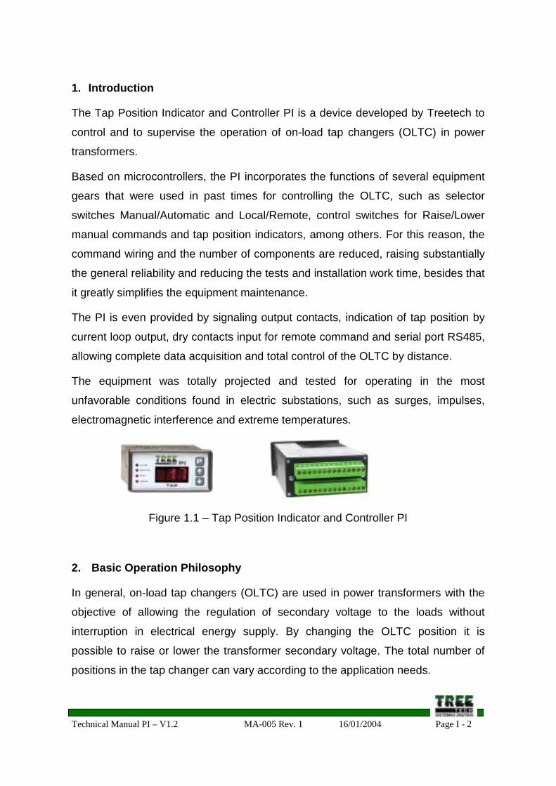
1. Introduction
The Tap Position Indicator and Controller PI is a device developed by Treetech to
control and to supervise the operation of on-load tap changers (OLTC) in power
transformers.
Based on microcontrollers, the PI incorporates the functions of several equipment
gears that were used in past times for controlling the OLTC, such as selector
switches Manual/Automatic and Local/Remote, control switches for Raise/Lower
manual commands and tap position indicators, among others. For this reason, the
command wiring and the number of components are reduced, raising substantially
the general reliability and reducing the tests and installation work time, besides that
it greatly simplifies the equipment maintenance.
The PI is even provided by signaling output contacts, indication of tap position by
current loop output, dry contacts input for remote command and serial port RS485,
allowing complete data acquisition and total control of the OLTC by distance.
The equipment was totally projected and tested for operating in the most
unfavorable conditions found in electric substations, such as surges, impulses,
electromagnetic interference and extreme temperatures.
Figure 1.1 – Tap Position Indicator and Controller PI
2. Basic Operation Philosophy
In general, on-load tap changers (OLTC) are used in power transformers with the
objective of allowing the regulation of secondary voltage to the loads without
interruption in electrical energy supply. By changing the OLTC position it is
possible to raise or lower the transformer secondary voltage. The total number of
positions in the tap changer can vary according to the application needs.
Technical Manual PI – V1.2 MA-005 Rev. 1 16/01/2004 Page I - 3
2.1 Manual/Automatic Command Modes
Regarding to the type of raise/lower commands for the OLTCs, there are two
possibilities: Manual Command or Automatic Command. By selecting the Manual
Command mode, the tap changes occur only when requested by the operator,
while the Automatic Mode enables the raise/lower tap commands sent by an
Automatic Voltage Regulator Relay (relay 90).
2.2 Local/Remote Command Modes
Regarding to the local from where can be performed the selections
Automatic/Manual and the commands raise/lower tap, there are three possibilities:
a) Local Command, by the PI front keypad;
b) Remote Command, by external dry contacts connected to the PI;
c) Remote Command, by the serial communication RS485, from a supervisor
system.
If the Local Command is selected, both of the remote command modes remain
blocked (in case of serial communication, only the information acquisition is
possible). If the Remote command were selected, the system operation by the front
keyboard remains blocked, liberating both of the remote command modes. In
general, only one of the both remote command options is used, because one
eliminates other’s necessity. It is possible, however, to have both remote modes
operating simultaneously.
Technical Manual PI – V1.2 MA-005 Rev. 1 16/01/2004 Page II - 1
Section II – Operation
Index of Subjects
Chapter Title Page
3 Local Operation of the PI II – 2
3.1 Primary indications in the display II – 2
3.2 Local/Remote and Manual/Automatic Selections II – 3
3.3 Raise/Lower Tap manual command II – 4
3.4 Error Conditions Alarms II – 5
3.4.1 Tap Position Reading Error (E08) II – 5
3.5 System Operation during error conditions II – 7
3.5.1 E08 - Tap Position Reading Error II – 7
Index of Pictures
Picture Title Page
3.1 Indication of the tap changer current position II - 3
3.2 Indication during a change of position in progress II - 3
3.3 Indication during an error condition occurrence II - 4
Technical Manual PI – V1.2 MA-005 Rev. 1 16/01/2004 Page II - 2
3. Local Operation of PI
The local operation of the PI is done by its front panel, using the P, ↑ and ↓ keys,
with the support of the equipment display.
3.1 Primary indications in the display
During the system autonomous operation, without the operator intervention by the
front keys, the PI display can accomplish one of the following indications:
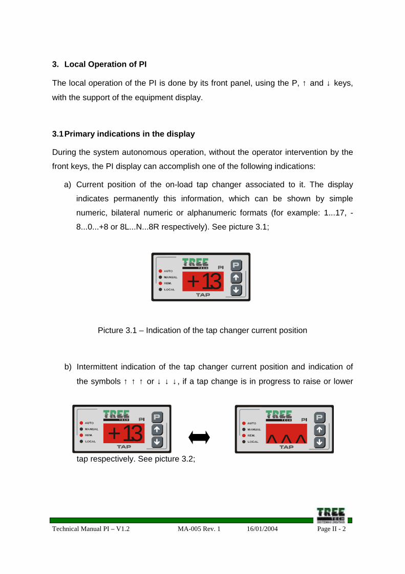
a) Current position of the on-load tap changer associated to it. The display
indicates permanently this information, which can be shown by simple
numeric, bilateral numeric or alphanumeric formats (for example: 1...17, -
8...0...+8 or 8L...N...8R respectively). See picture 3.1;
Picture 3.1 – Indication of the tap changer current position
b) Intermittent indication of the tap changer current position and indication of
the symbols ↑ ↑ ↑ or ↓ ↓ ↓ , if a tap change is in progress to raise or lower
tap respectively. See picture 3.2;
MESTRE
COMAND.
INDIVIDUAL
AUTO/REM.
MANUAL
T E C H
+ 13
MESTRE
COMAND.
INDIVIDUAL
AUTO/REM.
MANUAL
T E C H
+ 13MESTRE
COMAND.
INDIVIDUAL
AUTO/REM.
MANUAL
T E C H
^ ^ ^
Technical Manual PI – V1.2 MA-005 Rev. 1 16/01/2004 Page II - 3
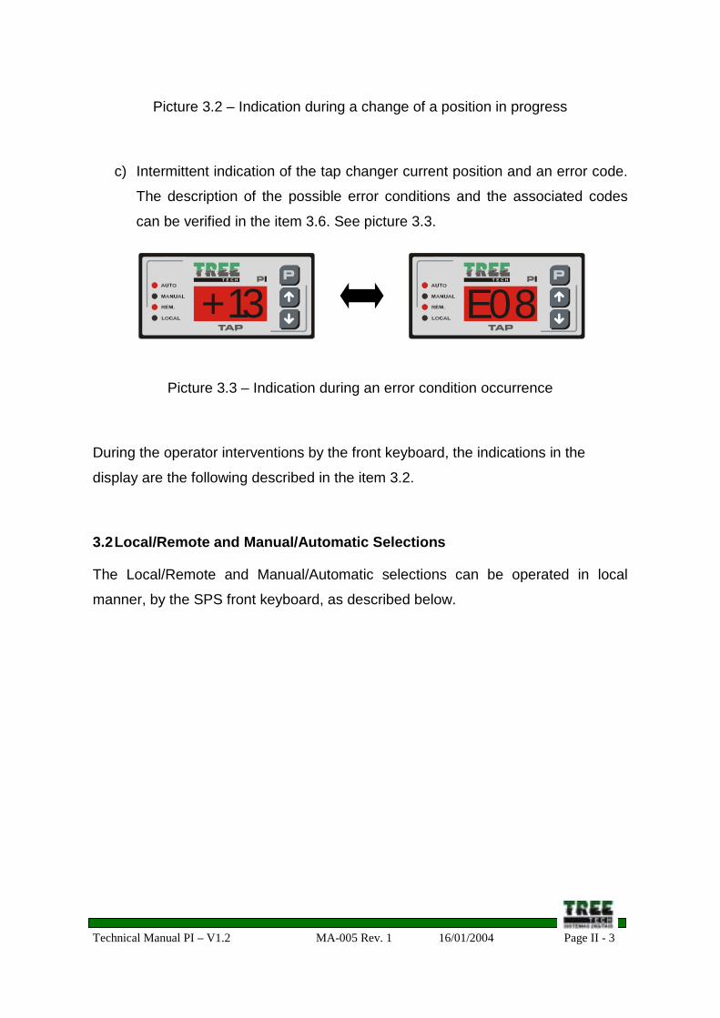
Picture 3.2 – Indication during a change of a position in progress
c) Intermittent indication of the tap changer current position and an error code.
The description of the possible error conditions and the associated codes
can be verified in the item 3.6. See picture 3.3.
Picture 3.3 – Indication during an error condition occurrence
During the operator interventions by the front keyboard, the indications in the
display are the following described in the item 3.2.
3.2 Local/Remote and Manual/Automatic Selections
The Local/Remote and Manual/Automatic selections can be operated in local
manner, by the SPS front keyboard, as described below.
MESTRE
COMAND.
INDIVIDUAL
AUTO/REM.
MANUAL
T E C H
+ 13MESTRE
COMAND.
INDIVIDUAL
AUTO/REM.
MANUAL
T E C H
E 0 8
Technical Manual PI – V1.2 MA-005 Rev. 1 16/01/2004 Page II - 4
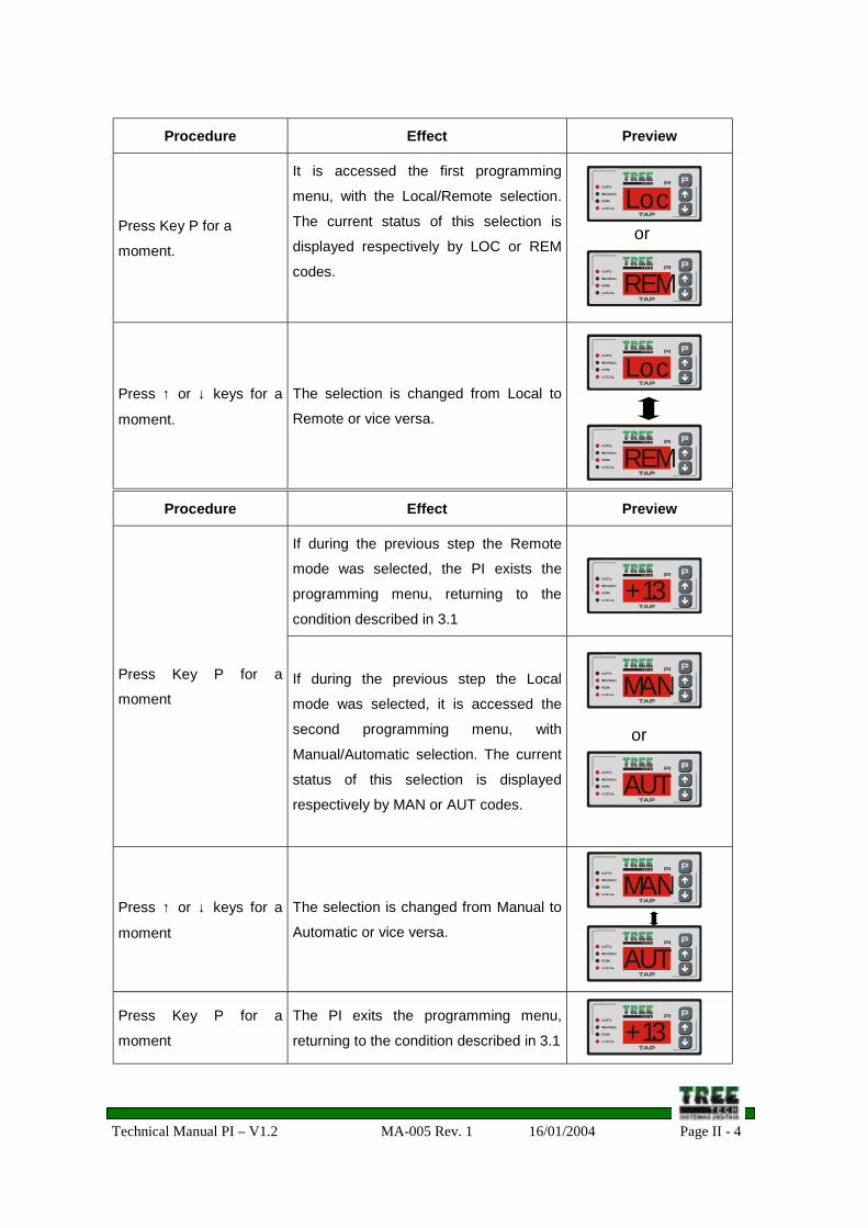
Procedure Effect Preview
Press Key P for a
moment.
It is accessed the first programming
menu, with the Local/Remote selection.
The current status of this selection is
displayed respectively by LOC or REM
codes.
Press ↑ or ↓ keys for a
moment.
The selection is changed from Local to
Remote or vice versa.
Procedure Effect Preview
If during the previous step the Remote
mode was selected, the PI exists the
programming menu, returning to the
condition described in 3.1
Press Key P for a
momentIf during the previous step the Local
mode was selected, it is accessed the
second programming menu, with
Manual/Automatic selection. The current
status of this selection is displayed
respectively by MAN or AUT codes.
Press ↑ or ↓ keys for a
moment
The selection is changed from Manual to
Automatic or vice versa.
Press Key P for a
moment
The PI exits the programming menu,
returning to the condition described in 3.1
or
or
MESTRE
COMAND.
INDIVIDUAL
AUTO/REM.
MANUAL
T E C H
L o c
MESTRE
COMAND.
INDIVIDUAL
AUTO/REM.
MANUAL
T E C H
R E M
MESTRE
COMAND.
INDIVIDUAL
AUTO/REM.
MANUAL
T E C H
L o c
MESTRE
COMAND.
INDIVIDUAL
AUTO/REM.
MANUAL
T E C H
R E M
MESTRE
COMAND.
INDIVIDUAL
AUTO/REM.
MANUAL
T E C H
+ 13
MESTRE
COMAND.
INDIVIDUAL
AUTO/REM.
MANUAL
T E C H
M A N
MESTRE
COMAND.
INDIVIDUAL
AUTO/REM.
MANUAL
T E C H
AU T
MESTRE
COMAND.
INDIVIDUAL
AUTO/REM.
MANUAL
T E C H
M A N
MESTRE
COMAND.
INDIVIDUAL
AUTO/REM.
MANUAL
T E C H
AU T
MESTRE
COMAND.
INDIVIDUAL
AUTO/REM.
MANUAL
T E C H
+ 13
Technical Manual PI – V1.2 MA-005 Rev. 1 16/01/2004 Page II - 5
3.3 Raise/Lower Tap manual command
The manual command to Raise and Low the position of the on-load tap changer
can be operated in local manner, using the ↑ and ↓ keys of the PI front, as
described below. These commands will only be followed if a previous selection of
the Local and Manual command modes is done.
Procedure Effect Preview
If the Remote mode were previously
selected, the display will show the REM
message during 1 second, indicating that
the command will not be followed,
because the PI is selected in this mode.
Press ↑ or ↓ keys for a
momentIf the Local and Manual command modes
are selected, the corresponding
command will be sent to the on-load tap
changer, and it will be displayed that the
tap change is in progress by the
periodical indication of the ↑↑↑ or ↓↓↓
symbols on the display.
3.4 Error Conditions Alarms
The alarm conditions of the PI are signalized in the front display by the error codes
listed below, besides that it allows its remote signaling by output contacts, as
described in sub-chapter 5.6.
All the error indications are automatically restarted, that is, the indication displayed
disappears when the error condition is eliminated, the same occurs with the
corresponding signaling contact, which returns to its repose condition.
or
MESTRE
COMAND.
INDIVIDUAL
AUTO/REM.
MANUAL
T E C H
R e m
MESTRE
COMAND.
INDIVIDUAL
AUTO/REM.
MANUAL
T E C H
^ ^^
MESTRE
COMAND.
INDIVIDUAL
AUTO/REM.
MANUAL
T E C H
Technical Manual PI – V1.2 MA-005 Rev. 1 16/01/2004 Page II - 6
Code Error Condition
E08 Tap position reading error
3.4.1 Tap Position Reading Error (E08)
It is caused by a reading fail of the current tap position of the load tap changer. It is
detected by the following reading consistency verifications. For each one of these
verifications is applied an error cause code, that is stored for posterior verification
by the maintenance staff.
a) Internal Error in the communication between the tap reading microcontroller
and the principal microcontroller. This reading error cause is stored as the
"C1" code,
b) Unstable tap position reading, in other words, floating much more fast than
what would be possible for the normal operation of the load tap changer.
This reading error cause is stored as the "C2" code,
c) Inconsistency in the tap position calculated from the several resistance
measurements accomplished in the potentiometric transmitter of the tap
changer. This reading error cause is stored as the "C3" code.
Without putting away another possibilities that can be verified, the possible causes
for this error are:
• Excessive electromagnetic interference in the measurement cables of the
potentiometric position transmitter, due to the usage of non-shielded cables (C2
cause);
• Excessive electromagnetic interference due to the lack of grounding of the
measurement cables shield of the potentiometric position transmitter (C2
cause);
• Excessive Electromagnetic interference due to the grounding of the
measurement cables shield of the potentiometric position transmitter in more
Technical Manual PI – V1.2 MA-005 Rev. 1 16/01/2004 Page II - 7
than one point, enabling the current circulation by the shield due to the ground
potential differences (C2 cause);
• Poor contact in the cursor of the potentiometric position transmitter or in the
connection cables from this one to the PI (C3 cause);
• Connection cables from the potentiometric position transmitter to the PI with
resistance superior to 8Ω per wire - very reduced size due to the roaming
distance (C3 cause);
• Connection cables from the potentiometric position transmitter to the PI with
different sizes or with different lengths in each wire (C3 cause);
• Defect in the PI tap measurement circuit (C1cause).
3.5 System Operation during errors presence
An ideal proceeding during any error occurrence is, naturally, detecting and
correcting its cause before continue the operation of the system.
However, when this proceeding is not possible to be done, or when there is no time
left to the problem correction, due to the prompt necessity of the system operation,
some emergency proceedings can be used, as suggested bellow. It must be taken
all cares related to the indicated Special Cautions, to prevent conditions with risk of
transformer trip by the protection operation or even with risk to the transformer
integrity.
3.5.1 E08 – Tap Reading Error
Error conditionand its Local
• E08 (tap reading error)
ContingencyProcedure
• The transformer that contains error can only be operated from the on-loadtap changer, as it is not possible to know by the PI what is the real tap positionof the tap changer.
SpecialCautions
• Use the mechanical position indicator in the OLTC motor cabinet forchecking of the raise/lower commands performed.
Technical Manual PI – V1.2 MA-005 Rev. 1 16/01/2004 Page III - 1
Section III – Project and Installation
Index of Subjects
Chapter Title Page
4 Topology for PI application III – 3
5 Inputs and Outputs III – 5
5.1 Auxiliary power and ground III – 5
5.2 Tap changer position measurement III – 5
5.2.1 Connection cables for tap measurement III – 5
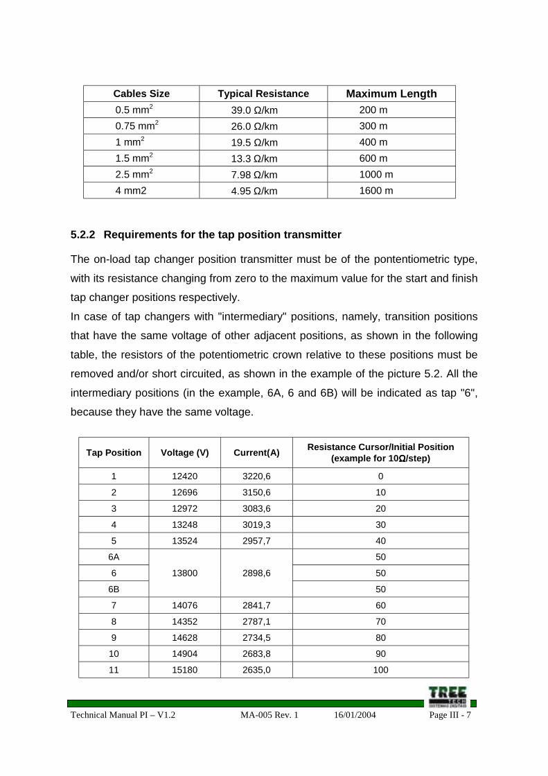
5.2.2 Requirements for the tap position transmitter III – 7
5.3 Analog output of tap changer position III – 8
5.4 Raise/Lower Tap output Contacts III – 9
5.5 Contact inputs for Remote Programming/Command III – 10
5.5.1 Local/Remote programming input III – 11
5.5.2 Manual/Automatic programming input III – 11
5.5.3 Raise/Lower Tap command Inputs III – 12
5.6 Output Relays for Signaling III – 13
5.7 Serial communication RS485 III – 14
6 Connection diagrams III – 14
7 Mechanical Installation III – 15
Index of Pictures
Picture Title Page
4.1 Topology of PI application III – 3
4.2 PI front panel III – 4
Technical Manual PI – V1.2 MA-005 Rev. 1 16/01/2004 Page III - 2
Index of Pictures (continues)
5.1 Shield connection of the tap measurement cables III – 6
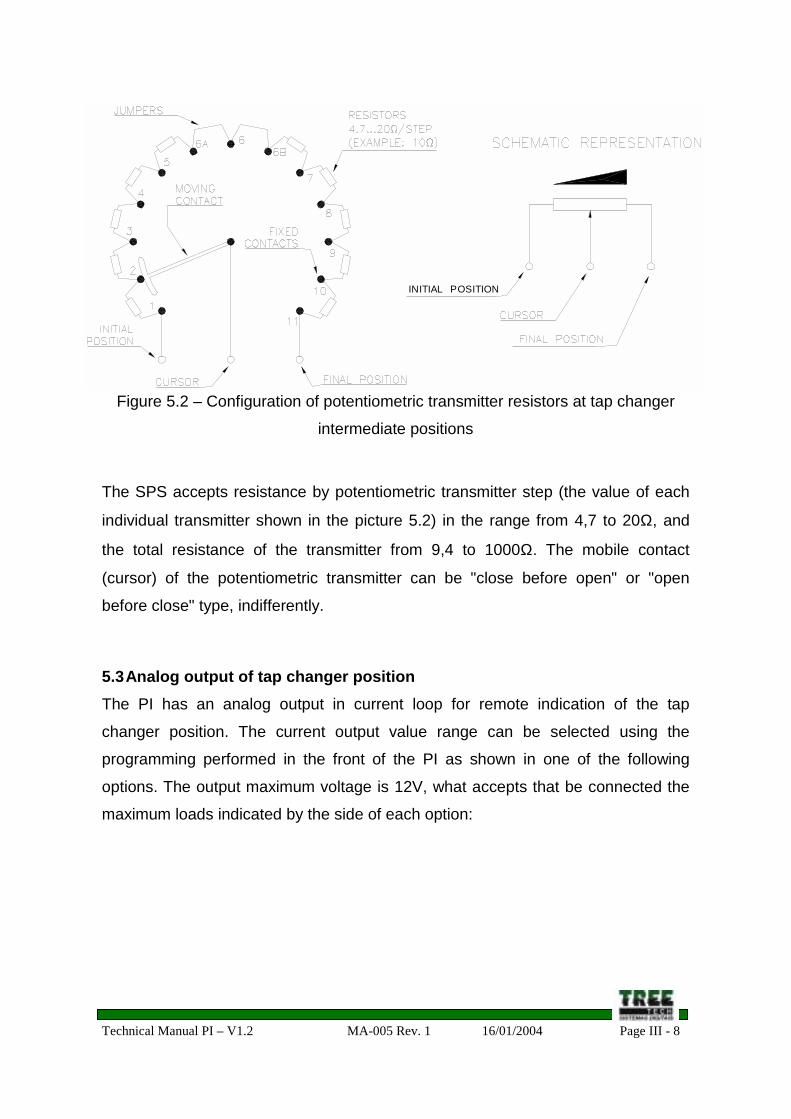
5.2Resistors configuration of the potentiometric transmitter in
intermediary positions of the on-load tap changerIII – 8
5.3.aManual/Automatic remote programming using a single
programming contactIII – 12
5.3.bManual/Automatic remote programming using two programming
contactsIII – 12
5.4Contacts connection of Raise/Lower external commands of
Automatic and Manual operation devicesIII – 13
5.5 PI signaling contacts III – 13
6.1 PI connection diagram III – 14
7.1 PI outline dimensions III – 15
Technical Manual PI – V1.2 MA-005 Rev. 1 16/01/2004 Page III - 3
4. Topology for PI application
For each On-Load Tap Changer it is used a unity of the Position Indicator and
Controller PI. The serial communication RS485 ports of the PI allow the serial
communication of them with an external data acquisition system (supervisor
system). See figure 4.1.
Figure 4.1 – Topology of PI application
OLTC
TRANSFORMER 1
TAP
Mea
sure
men
t
Rai
se/L
ower
Tap
com
man
ds
...
Serial CommunicationRS 485 for Supervisor
System
PI
...
PIPIT E C H
6lT E C H
6lT E C H
6l
TRANSFORMER 2 TRANSFORMER 3
OLTC OLTC
TAP
Mea
sure
men
t
TAP
Mea
sure
men
t
Rai
se/L
ower
Tap
com
man
ds
Rai
se/L
ower
Tap
com
man
ds
MESTRE
COMAND .
INDIVIDUAL
AUTO/REM.
MANUAL
T E C H
6lMESTRE
COMAND .
INDIVIDUAL
AUTO/REM.
MANUAL
T E C H
6lMESTRE
COMAND .
INDIVIDUAL
AUTO/REM.
MANUAL
T E C H
6l
Technical Manual PI – V1.2 MA-005 Rev. 1 16/01/2004 Page III - 4
In the picture 4.2 it is shown the PI front panel, composed by:
1) Indicator LED for the command mode Manual selected (in Automatic mode this
LED turns off);
2) Indicator LED for the command mode Remote selected (in Local mode this LED
turns off);
3) P, ↑ and ↓ front keys, with the functions:
• Manual/Automatic and Local/Remote selections;
• Raise/Lower tap position manual commands;
• PI configuration.
4) Three-digit display for indicating:
• Current tap position;
• Position change in progress;
• Support to the Manual/Automatic and Local/Remote selections;
• Support to the PI configuration;
• Indication codes for error conditions.
Figure 4.2 – PI Front panel
1
23
4
MESTRE
MANUA
AUTO
MASTER
MANUALAUTO
INDIV.
FOLLOWERT E C H
+13MESTRE
COMAND.
INDIVIDUAL
AUTO/REM.
MANUAL
T E C H
+ 13
Technical Manual PI – V1.2 MA-005 Rev. 1 16/01/2004 Page III - 5
5. Inputs and OutputsThe following described Inputs and Outputs are available in the PI. A general vision
of all the inputs and outputs can be observed in chapter 6.
5.1 Auxiliary power and GroundThe PI is capable to operate with auxiliary power in the range from 85 to 265V, in
AC or DC, 50 or 60Hz, with consumption lower than 6W. It must be effected the
connection of the terminal corresponding to the ground.
♦ Power input: terminals 16 and 17;
♦ Ground: terminal 15.
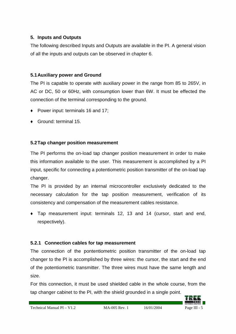
5.2 Tap changer position measurement
The PI performs the on-load tap changer position measurement in order to make
this information available to the user. This measurement is accomplished by a PI
input, specific for connecting a potentiometric position transmitter of the on-load tap
changer.
The PI is provided by an internal microcontroller exclusively dedicated to the
necessary calculation for the tap position measurement, verification of its
consistency and compensation of the measurement cables resistance.
♦ Tap measurement input: terminals 12, 13 and 14 (cursor, start and end,
respectively).
5.2.1 Connection cables for tap measurementThe connection of the pontentiometric position transmitter of the on-load tap
changer to the PI is accomplished by three wires: the cursor, the start and the end
of the potentiometric transmitter. The three wires must have the same length and
size.
For this connection, it must be used shielded cable in the whole course, from the
tap changer cabinet to the PI, with the shield grounded in a single point.
Technical Manual PI – V1.2 MA-005 Rev. 1 16/01/2004 Page III - 6
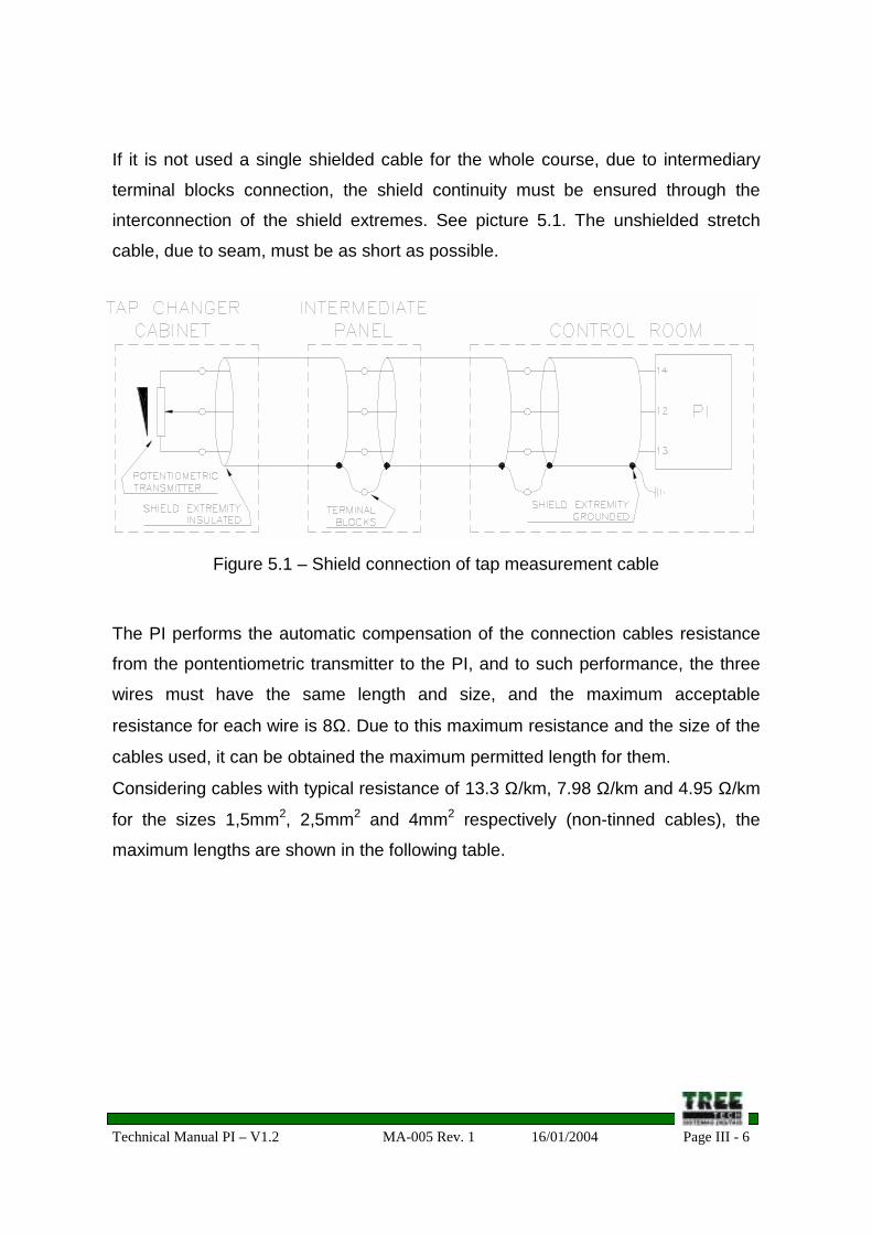
If it is not used a single shielded cable for the whole course, due to intermediary
terminal blocks connection, the shield continuity must be ensured through the
interconnection of the shield extremes. See picture 5.1. The unshielded stretch
cable, due to seam, must be as short as possible.
Figure 5.1 – Shield connection of tap measurement cable
The PI performs the automatic compensation of the connection cables resistance
from the pontentiometric transmitter to the PI, and to such performance, the three
wires must have the same length and size, and the maximum acceptable
resistance for each wire is 8Ω. Due to this maximum resistance and the size of the
cables used, it can be obtained the maximum permitted length for them.
Considering cables with typical resistance of 13.3 Ω/km, 7.98 Ω/km and 4.95 Ω/km
for the sizes 1,5mm2, 2,5mm2 and 4mm2 respectively (non-tinned cables), the
maximum lengths are shown in the following table.
Technical Manual PI – V1.2 MA-005 Rev. 1 16/01/2004 Page III - 7
♦ Raise/Lower Tap command inputs: terminals 5 (Raise) and 6 (Lower);
♦ Common point for all the inputs: terminal 9.
Technical Manual PI – V1.2 MA-005 Rev. 1 16/01/2004 Page III - 11
5.5.1 Local/Remote Programming
This input allows the remote selection of the Local/Remote command mode.
A pulsed command must be used; this command mode is reversed (from Local to
Remote or vice versa) every time the contact connected to the programming input
is momentarily closed. If the contact closes and keep closed, there will be an only
inversion in the Local/Remote command mode. Additional inversions will be
possible only if the contact opens and returns to close.
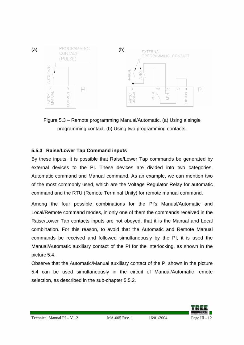
5.5.2 Manual/Automatic programming inputThis input allows the remote selection of the Manual/Automatic command mode. It
must be used command by pulse; the command mode is reversed (from Manual to
Automatic or vice versa) every time the contact connected to the Manual/Automatic
programming input is momentary closed. If this contact close and keep closed,
there will be an only inversion in the Manual/Automatic command mode. Additional
inversions will be possible only if the contact opens and returns to close.
It is also possible to perform the Manual/Automatic selection using two
independent contacts instead of a single contact, being one of them with the
Manual function and the other one with the Automatic function. For this proceeding,
it must be used the Manual/Automatic reversible auxiliary contact. Comparing to
the picture 5.3.a, where it is shown the alternative of a single command contact,
and the picture 5.3.b, with the alternative of independent contacts, it can be
observed that in both cases, the programming input receives pulses for state
inversion, but in the second case the pulse only reaches this input if the contact
corresponding to the opposite condition to the current SPS programming is closed.
If the contact corresponding to the current SPS condition is closed, this input does
not receive the inversion pulse and it is kept in the current condition.
Observe that the Automatic/Manual auxiliary contact of the SPS shown in the
picture 5.3.b is used simultaneously in the circuit of the Raise/Lower Tap external
command contacts, as described in the sub-chapter 5.5.3.
Technical Manual PI – V1.2 MA-005 Rev. 1 16/01/2004 Page III - 12
(a) (b)
Figure 5.3 – Remote programming Manual/Automatic. (a) Using a single
programming contact. (b) Using two programming contacts.
5.5.3 Raise/Lower Tap Command inputsBy these inputs, it is possible that Raise/Lower Tap commands be generated by
external devices to the PI. These devices are divided into two categories,
Automatic command and Manual command. As an example, we can mention two
of the most commonly used, which are the Voltage Regulator Relay for automatic
command and the RTU (Remote Terminal Unity) for remote manual command.
Among the four possible combinations for the PI's Manual/Automatic and
Local/Remote command modes, in only one of them the commands received in the
Raise/Lower Tap contacts inputs are not obeyed, that it is the Manual and Local
combination. For this reason, to avoid that the Automatic and Remote Manual
commands be received and followed simultaneously by the PI, it is used the
Manual/Automatic auxiliary contact of the PI for the interlocking, as shown in the
picture 5.4.
Observe that the Automatic/Manual auxiliary contact of the PI shown in the picture
5.4 can be used simultaneously in the circuit of Manual/Automatic remote
selection, as described in the sub-chapter 5.5.2.
Technical Manual PI – V1.2 MA-005 Rev. 1 16/01/2004 Page III - 13
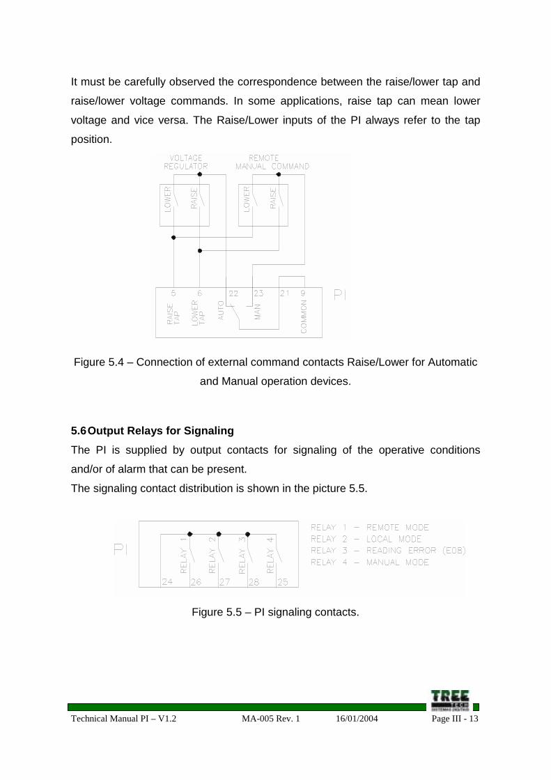
It must be carefully observed the correspondence between the raise/lower tap and
raise/lower voltage commands. In some applications, raise tap can mean lower
voltage and vice versa. The Raise/Lower inputs of the PI always refer to the tap
position.
Figure 5.4 – Connection of external command contacts Raise/Lower for Automatic
and Manual operation devices.
5.6 Output Relays for SignalingThe PI is supplied by output contacts for signaling of the operative conditions
and/or of alarm that can be present.
The signaling contact distribution is shown in the picture 5.5.
Figure 5.5 – PI signaling contacts.
Technical Manual PI – V1.2 MA-005 Rev. 1 16/01/2004 Page III - 14
5.7 Serial Communication RS485Each PI has a serial communication port RS485. By this communication channel
can be accessed all the information, selections and commands of PI.
It must be used a 120Ω termination resistor in each extreme of the communication
network. The cable used must be the shielded twisted-pair type, grounded in a
single point.
If it is not used a single shielded twisted-pair cable for the whole course, due to
intermediary terminal blocks connection, it must be ensured the shield continuity,
by connecting the shield extremes of the several cables. The cable stretch without
shield, due to seam, must be as short as possible. Maximum length of the RS485
serial communication cables must be 1300 meters.
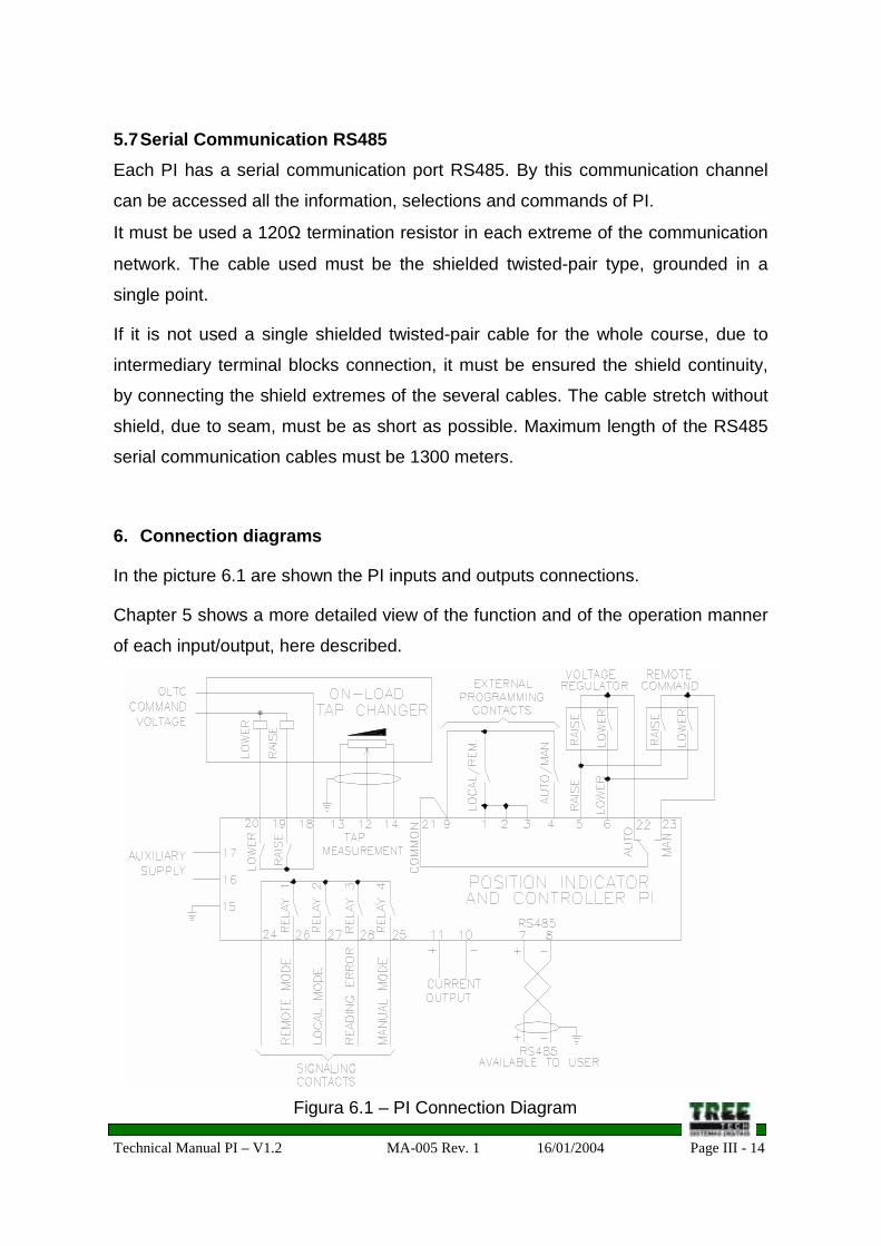
6. Connection diagrams
In the picture 6.1 are shown the PI inputs and outputs connections.
Chapter 5 shows a more detailed view of the function and of the operation manner
of each input/output, here described.
Figura 6.1 – PI Connection Diagram
Technical Manual PI – V1.2 MA-005 Rev. 1 16/01/2004 Page III - 15
7. Mechanical Installation
The PI must be installed protected from weather, inside the control panels or
sheltered in building. In any of these cases, there must be an anti-condensation
system.
The PI is appropriate for installation of the built-in type; it can be fixed, for an
example, in control cubicle door or front plate. The fixing straps are provided with
the PI. In the picture 7.1 are shown the equipment outline dimensions, and the
dimensions of the sheet cutout for its insertion. Special attention must be given to
the thickness of the painting layers in the sheet where the is going to be inserted,
because in some cases, when a large thickness painting is used, the lowering of
the indenting area can even block the equipment insertion.
The connection terminals are installed in 2 removable connectors in the rear part of
the PI, favoring the connections. It can be used cables from 0.5 to 2.5mm2, nude or
with terminals of pin (or needle) type.
REMOVABLECONNECTORS
Figura 7.1 – PI Outline Dimensions
Technical Manual PI – V1.2 MA-005 Rev. 1 16/01/2004 Page IV - 1
Section IV – Start-up
Index of Subjects
Chapter Title Page
8 Proceeding to start the operation IV – 2
9 Parametering IV – 3
9.1 Parameter ADR IV – 4
9.2 Parameter TAP IV – 4
9.3 Parameter IDC IV – 5
9.4 Parameter CNT IV – 6
9.5 Parameter RES IV – 6
9.6 Parameter CMT IV – 7
9.7 Parameter OCS IV – 8
Index of Pictures
Picture Title Page
9.1Individual resistors (step resistance) of the on-load tap
changer potentiometric transmitterIV – 7
Technical Manual PI – V1.2 MA-005 Rev. 1 16/01/2004 Page IV - 2
8. Proceeding to start the operation
As soon as the equipment installation according to the Section III of this manual is
done, the starting the operation must follows the following basic steps.
• Disable the OLTCs commands (example: turn off the motors switches or select
the OLTC for Local command) before energizing the PI. During this period, the
commands that maybe necessary for the tap change must be performed in the
proper tap changer cabinet;
• Check the correction of the electric connections (e.g.: by continuity tests);
• Energize the PI with the power voltage of 85 ~ 265Vdc/Vac;
• Perform the whole PI parameterization, according to the instructions in the sup-
chapter 9;
• Put the PI in Local and Manual command modes (see sub-chapter 3.2);
• If there is no error indications (see sub-chapter 3.6), enable the tap changers
remote command, allowing the command by the PI;
• Command manually the OLTC by the corresponding PI, passing by all the tap
positions. Observe if there is no inversion between the raise and lower tap
commands, and also observe if the tap indication is correct in all the positions
and if there is no occurrence of tap reading errors (E08);
• Simulate the several operative conditions (local, remote, manual and
automatic), verifying the operation of the signaling contacts;
• Select the final configuration desired for operation, that is, command modes
Manual or Automatic and Local or Remote.
Technical Manual PI – V1.2 MA-005 Rev. 1 16/01/2004 Page IV - 3
9. Parametering
To ensure the correct operation of the PI, several parameters must be settle in the
it, which will provide the equipment the necessary information for its operation. Its
front keyboard can perform the adjustments, with the display assistance, or by the
serial communication port available to the user.
The proceeding to access the several adjustment parameters of the PI is
presented below. Observe that, to access the parameterization, it is primarily
necessary to enter in the programming menu.
Forward, in the sub-chapters 9.1 to 9.7, is the description of each parameter, and
all the advises for their selection.
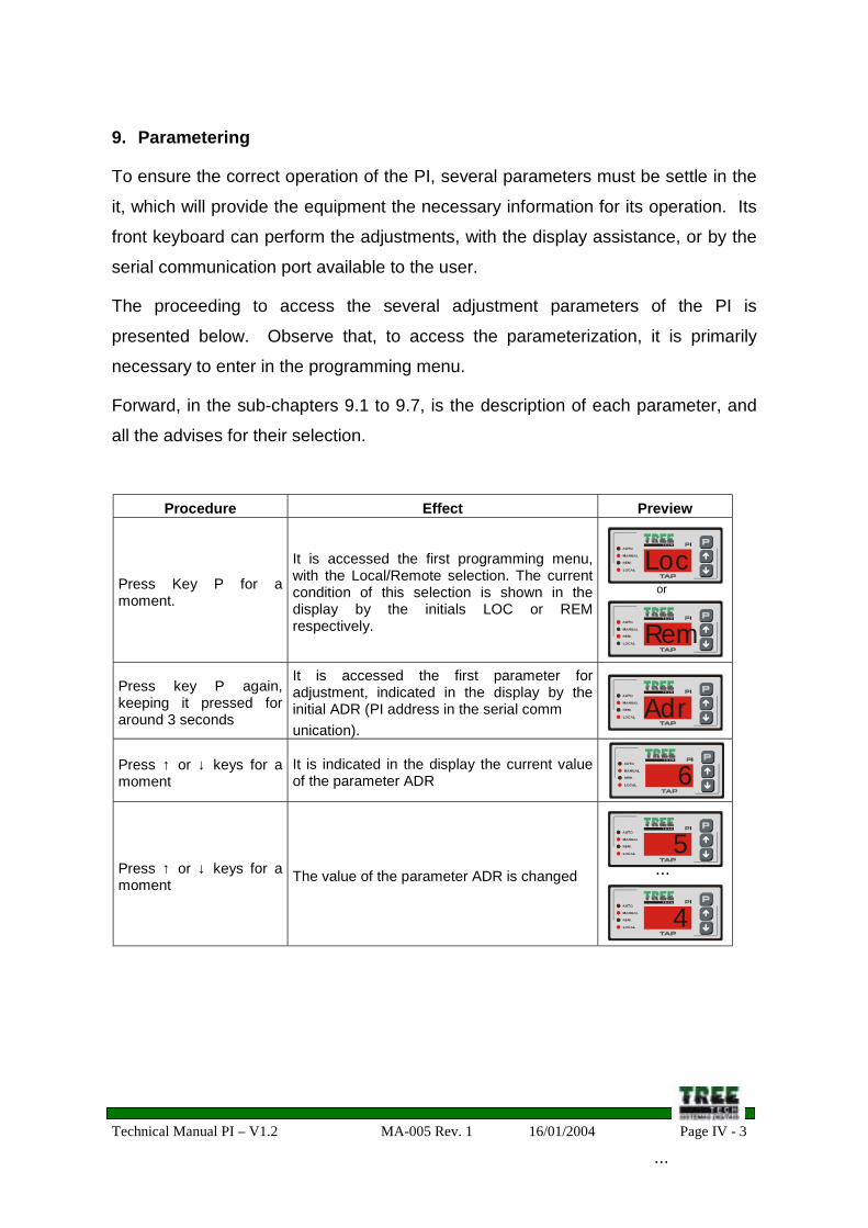
Procedure Effect Preview
Press Key P for amoment.
It is accessed the first programming menu,with the Local/Remote selection. The currentcondition of this selection is shown in thedisplay by the initials LOC or REMrespectively.
Press key P again,keeping it pressed foraround 3 seconds
It is accessed the first parameter foradjustment, indicated in the display by theinitial ADR (PI address in the serial communication).
Press ↑ or ↓ keys for amoment
It is indicated in the display the current valueof the parameter ADR
Press ↑ or ↓ keys for amoment The value of the parameter ADR is changed
or
...
...
MESTRE
COMAND.
INDIVIDUAL
AUTO/REM.
MANUAL
T E C H
R e m
MESTRE
COMAND.
INDIVIDUAL
AUTO/REM.
MANUAL
T E C H
L o c
MESTRE
COMAND.
INDIVIDUAL
AUTO/REM.
MANUAL
T E C H
A d r
MESTRE
COMAND.
INDIVIDUAL
AUTO/REM.
MANUAL
T E C H
6
MESTRE
COMAND.
INDIVIDUAL
AUTO/REM.
MANUAL
T E C H
5
MESTRE
COMAND.
INDIVIDUAL
AUTO/REM.
MANUAL
T E C H
4
Technical Manual PI – V1.2 MA-005 Rev. 1 16/01/2004 Page IV - 4
Procedure Effect Preview
Press Key P for amoment.
Press ↑ or ↓ keys for amoment
Press ↑ or ↓ keys for amoment
Repeating these 3 steps, the all the further PIparameters can be accessed and edited :- TAP (total number of taps of the tap
changer)- IDC (tap indication type)- CNT (central tap of the tap changer)- RES (resistance by step of the
potentiometric transmitter)- CMT (time for tap change)- OCS (output current mA)
Press Key P for amoment.
The PI leaves the parameterization menu,returning to the indications described in 3.1 (ingeneral, the current tap position)
9.1 Parameter ADR
It is the PI address in the serial communication with a supervisory system. As
general rule, each device connected to the same communication network must
have a single address, without repetition.
Adjustment range: 0 to 31.
9.2 Parameter TAP
It is the total number of on-load tap changer positions. In cases of tap changers
with “intermediary” positions, in other words, transition positions that have the
same voltage than other adjacent positions, as exemplified in the following table,
the parameter TAP value must not include the intermediary positions, because
these positions (in the examples: 6A, 6 and 6B) will be indicated as tap “6”, as they
have the same voltage. In this example, the parameter TAP is programmed as 11.
MESTRE
COMAND.
INDIVIDUAL
AUTO/REM.
MANUAL
T E C H
4
MESTRE
COMAND.
INDIVIDUAL
AUTO/REM.
MANUAL
T E C H
3
MESTRE
COMAND.
INDIVIDUAL
AUTO/REM.
MANUAL
T E C H
2MESTRE
COMAND.
INDIVIDUAL
AUTO/REM.
MANUAL
T E C H
1
MESTRE
COMAND.
INDIVIDUAL
AUTO/REM.
MANUAL
T E C H
+ 13
Technical Manual PI – V1.2 MA-005 Rev. 1 16/01/2004 Page IV - 5
Tap position Voltage (V) Current (A)1 12420 3220.62 12696 3150.63 12972 3083.64 13248 3019.35 13524 2957.7
6A6
6B13800 2898.6
7 14076 2841.78 14352 2787.19 14628 2734.5
10 14904 2683.811 15180 2635.0
Adjustment range: 2 to 50.
9.3 Parameter IDC
It is the tap indication type adopted for presentation in the PI display, that generally
follows the same indication type used in the proper on-load tap changer. There are
four indication options, shown in the following table.
In the example 1, it is presented a tap changer with a total tap number equal 17
(TAP=17), with the neuter position (0 and N) centralized in the Bilateral numerical
and Alphanumerical indications. The example 2 presents a tap changer with a total
2 Alphanumerical 8L ... N ... 8R 12L ... N ... 20R
3 Inverted alphanumerical 8R ... N ... 8L 12R ... N ... 20L
4 Simple numerical 1 ... 17 1 ... 33
Technical Manual PI – V1.2 MA-005 Rev. 1 16/01/2004 Page IV - 6
of 33 taps, with the neuter position decentralized in the Bilateral numerical and
Alphanumerical indications.
9.4 Parameter CNT
It is the position, counted from the beginning of the measurement range, where the
on-load “neuter” tap changer is found. This parameter will have practical effects
only when the Bilateral numerical and Alphanumerical indication types are selected
(see sub-chapter 9.3), because it allows that the tap changer positions with raise
and lower ranges of asymmetric voltage be indicated.
The following table exemplifies the effect caused by this parameter in the tap
indication for a 33-position tap changer and Bilateral numerical and Inverted
alphanumerical indication types.
Parameter CNTBilateral numerical
ExampleInverted alphanumerical
Example
15 -14 ... 0 ... +18 14R ... N ... 18L
16 -15 ... 0 ... +17 15R ... N ... 17L
17 -16 ... 0 ... +16 16R ... N ... 16L
18 -17 ... 0 ... +15 17R ... N ... 15L
19 -18 ... 0 ... +14 18R ... N ... 14L
Adjustment range: 2 to 50.
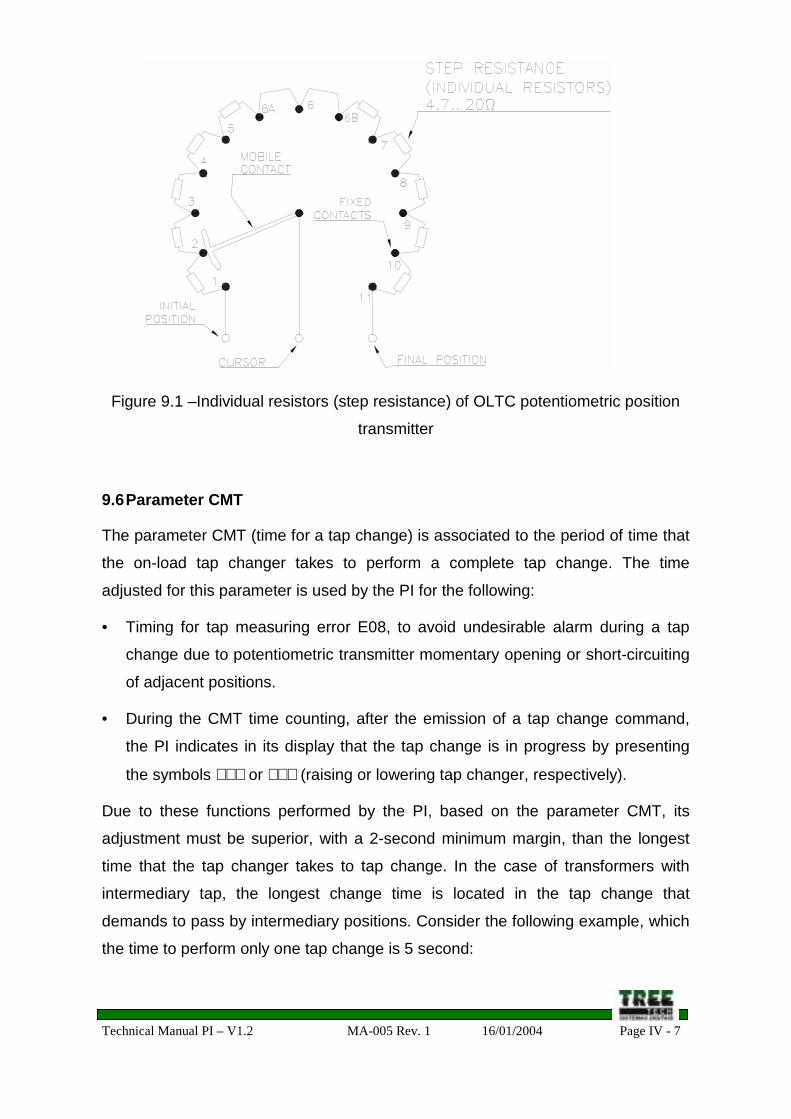
9.5 Parameter RES
It is the resistance by step of the on-load tap changer potentiometric transmitter (in
other words, each individual resistor value, shown in the picture 9.1).
Adjustment range: 4.7 to 20Ω.
Technical Manual PI – V1.2 MA-005 Rev. 1 16/01/2004 Page IV - 7
Figure 9.1 –Individual resistors (step resistance) of OLTC potentiometric position
transmitter
9.6 Parameter CMT
The parameter CMT (time for a tap change) is associated to the period of time that
the on-load tap changer takes to perform a complete tap change. The time
adjusted for this parameter is used by the PI for the following:
• Timing for tap measuring error E08, to avoid undesirable alarm during a tap
change due to potentiometric transmitter momentary opening or short-circuiting
of adjacent positions.
• During the CMT time counting, after the emission of a tap change command,
the PI indicates in its display that the tap change is in progress by presenting
the symbols ∧∧∧ or ∨∨∨ (raising or lowering tap changer, respectively).
Due to these functions performed by the PI, based on the parameter CMT, its
adjustment must be superior, with a 2-second minimum margin, than the longest
time that the tap changer takes to tap change. In the case of transformers with
intermediary tap, the longest change time is located in the tap change that
demands to pass by intermediary positions. Consider the following example, which
the time to perform only one tap change is 5 second:
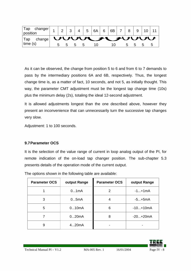
Technical Manual PI – V1.2 MA-005 Rev. 1 16/01/2004 Page IV - 8
Tap changerposition 1 2 3 4 5 6A 6 6B 7 8 9 10 11
Tap changetime (s) 5 5 5 5 10 10 5 5 5 5
As it can be observed, the change from position 5 to 6 and from 6 to 7 demands to
pass by the intermediary positions 6A and 6B, respectively. Thus, the longest
change time is, as a matter of fact, 10 seconds, and not 5, as initially thought. This
way, the parameter CMT adjustment must be the longest tap change time (10s)
plus the minimum delay (2s), totaling the ideal 12-second adjustment.
It is allowed adjustments longest than the one described above, however they
present an inconvenience that can unnecessarily turn the successive tap changes
very slow.
Adjustment: 1 to 100 seconds.
9.7 Parameter OCS
It is the selection of the value range of current in loop analog output of the PI, for
remote indication of the on-load tap changer position. The sub-chapter 5.3
presents details of the operation mode of the current output.
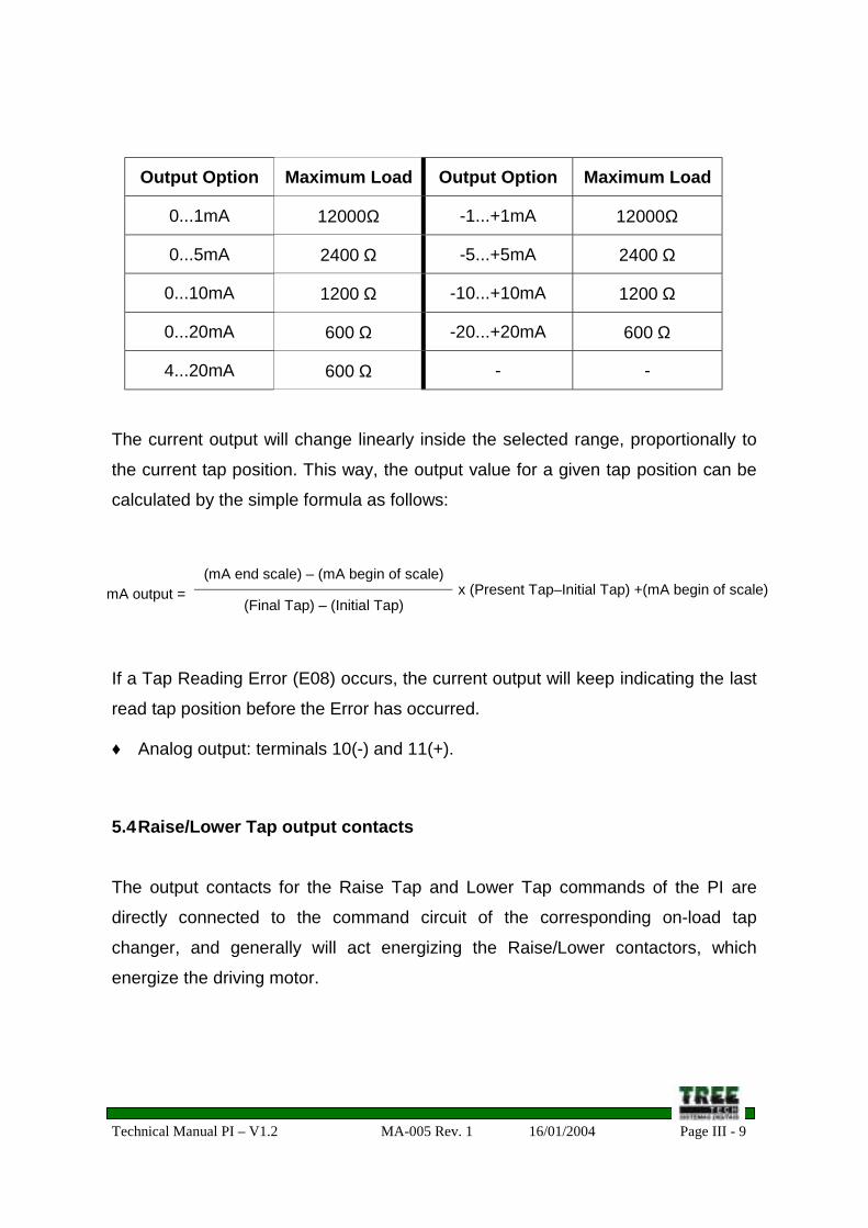
The options shown in the following table are available:
Parameter OCS output Range Parameter OCS output Range
1 0...1mA 2 -1...+1mA
3 0...5mA 4 -5...+5mA
5 0...10mA 6 -10...+10mA
7 0...20mA 8 -20...+20mA
9 4...20mA - -
Technical Manual PI – V1.2 MA-005 Rev. 1 16/01/2004 Page V - 1
Section V – Troubleshooting
Index of subjects
Chapter Title Page
10 Troubleshooting V – 2
10.1 Manual/Automatic Selection V – 2
10.2 Raise/Lower tap commands V – 2
10.3 Local and remote indication of tap position V – 3
10.7 Error indication E08 V – 4
Technical Manual PI – V1.2 MA-005 Rev. 1 16/01/2004 Page V - 2
10. Troubleshooting
If difficulties or troubles appear in the operation the PI, we suggest you to consultthe possible causes and simple solutions presented below. If this information is notsufficient to solve the difficulties, please get in contact with Treetech's technicalassistance or its authorized agent.
10.1 Manual/Automatic Selection
• The PI does not allow the Manual/Automatic selection to be performed in itsfront panel
Probable Causes Possible SolutionsThe PI is in Remote operation mode,therefore, it only follows the selectionsperformed via dry contacts or via serialcommunication
Select the PI for Local mode (see sub-chapter3.2)
• The PI does not allow the Manual/Automatic selection to be performed via drycontacts or via serial communication
Probable Causes Possible SolutionsThe PI is in Local operation mode,therefore, it only follows the selectionsperformed in its front panel
Select the PI for Remote mode (see sub-chapter3.2)
10.2 Raise/Lower tap commands
• The PI does not follow the Raise and Lower tap commands performed in itsfront panel
Probable Causes Possible SolutionsThe PI is in Remote operation mode,therefore, it only follows the selectionsperformed via dry contacts or via serialcommunication
Select the PI for Local mode (see sub-chapter3.2)
The PI is in the Automatic mode, there fore,it only follows the commands generated bythe voltage regulator relay (or similardevice)
Select the PI for Manual mode (see sub-chapter3.2)
The on-load tap changer is in Local modeor it is turned off, or there is nopower/command supply, or any chargingswitch is turned off
Verify the on-load tap changer, thepower/command circuit charging switches andthe auxiliary power.
Technical Manual PI – V1.2 MA-005 Rev. 1 16/01/2004 Page V - 3
• The PI does not follow the Raise and Lower tap commands performed via drycontacts or via serial communication
Probable Causes Possible SolutionsThe PI is in Local operation mode,therefore, it only follows the selectionsperformed in its front panel
Select the PI for Remote mode (see sub-chapter3.2)
The PI is in the Automatic mode, there fore,it only follows the commands generated bythe voltage regulator relay (or similardevice)
Select the PI for Manual mode (see sub-chapter3.2)
The on-load tap changer is in the Localmode or it is turned off, or there is nopower/command supply, or any chargingswitch is turned off
Verify the on-load tap changer, thepower/command circuit charging switches andthe auxiliary power.
10.3 Local and Remote Tap position indications
• The indication of the tap position in the front panel of the PI does notcorrespond to the real position of the tap changer
Probable Causes Possible SolutionsIt was not selected the correct option of PItap indication type
Select the indication type corresponding to yourtap changer according to the instructionsdescribed in the sub-chapter 9.3
It was not selected the correct “neuter” tapposition option of the tap changer, related toindication of bilateral numerical (-/+) oralphanumerical (L/R) type.
Select the "neuter" tap position of the tapchanger according to the instructions describedin the sub-chapter 9.4
• The on-load tap changer has bilateral numerical (-/+) or alphanumerical (L/R)tap indication, and the tap position indication in the front of the PI is inverted inrelation to the real position
Probable Causes Possible SolutionsIt was not selected the correct option of tapindication type of the PI
Select the indication type corresponding to yourtap changer according to the instructionsdescribed in the sub-chapter 9.3
Technical Manual PI – V1.2 MA-005 Rev. 1 16/01/2004 Page V - 4
• The PI's current output mA for remote indication of tap position does notcorrespond to the expected value
Probable Causes Possible SolutionsIt was not selected the correct option of thePI's output current range
Select the wanted output current rangeaccording to the instructions described in thesub-chapter 9.7
The calculation of the expected value forthe current output is mistaken
See the calculation formula of the expectedvalue for the current output in the sub-chapter5.3
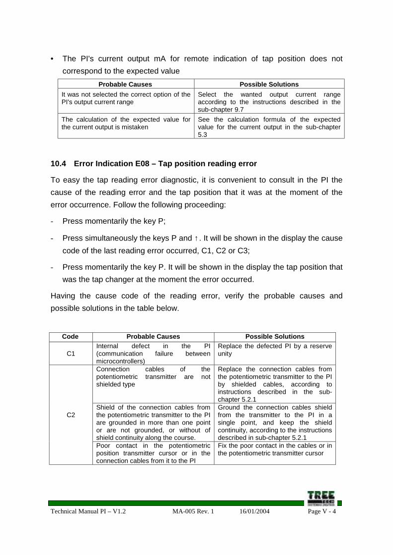
10.4 Error Indication E08 – Tap position reading error
To easy the tap reading error diagnostic, it is convenient to consult in the PI thecause of the reading error and the tap position that it was at the moment of theerror occurrence. Follow the following proceeding:
- Press momentarily the key P;
- Press simultaneously the keys P and ↑ . It will be shown in the display the causecode of the last reading error occurred, C1, C2 or C3;
- Press momentarily the key P. It will be shown in the display the tap position thatwas the tap changer at the moment the error occurred.
Having the cause code of the reading error, verify the probable causes andpossible solutions in the table below.
Code Probable Causes Possible Solutions
C1Internal defect in the PI(communication failure betweenmicrocontrollers)
Replace the defected PI by a reserveunity
Connection cables of thepotentiometric transmitter are notshielded type
Replace the connection cables fromthe potentiometric transmitter to the PIby shielded cables, according toinstructions described in the sub-chapter 5.2.1
Shield of the connection cables fromthe potentiometric transmitter to the PIare grounded in more than one pointor are not grounded, or without ofshield continuity along the course.
Ground the connection cables shieldfrom the transmitter to the PI in asingle point, and keep the shieldcontinuity, according to the instructionsdescribed in sub-chapter 5.2.1
C2
Poor contact in the potentiometricposition transmitter cursor or in theconnection cables from it to the PI
Fix the poor contact in the cables or inthe potentiometric transmitter cursor
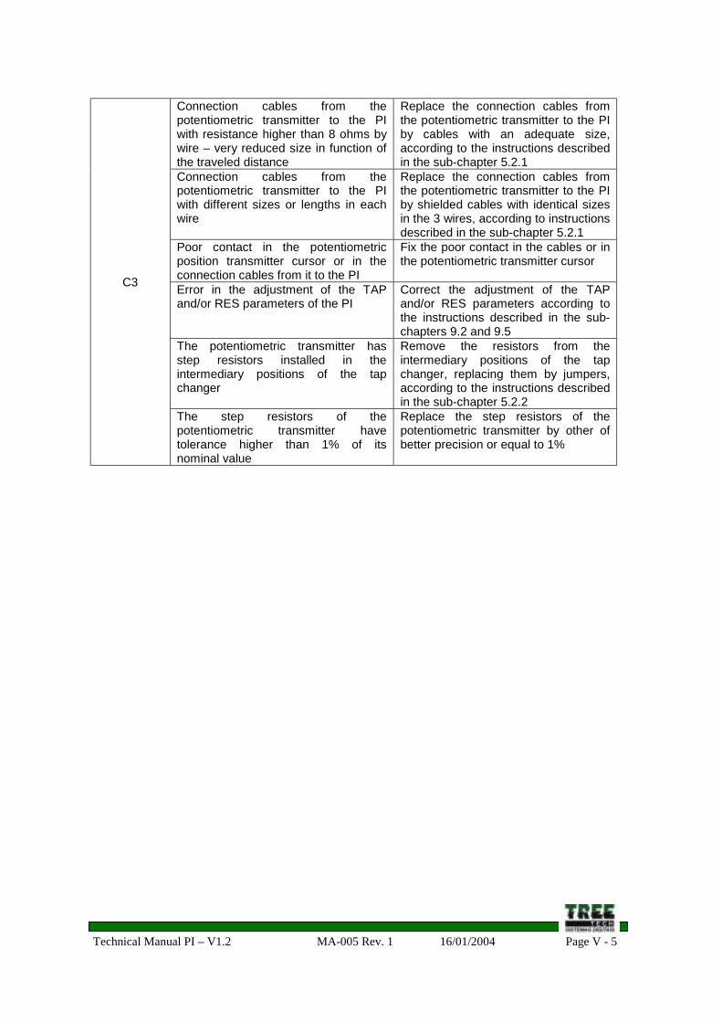
Technical Manual PI – V1.2 MA-005 Rev. 1 16/01/2004 Page V - 5
Connection cables from thepotentiometric transmitter to the PIwith resistance higher than 8 ohms bywire – very reduced size in function ofthe traveled distance
Replace the connection cables fromthe potentiometric transmitter to the PIby cables with an adequate size,according to the instructions describedin the sub-chapter 5.2.1
Connection cables from thepotentiometric transmitter to the PIwith different sizes or lengths in eachwire
Replace the connection cables fromthe potentiometric transmitter to the PIby shielded cables with identical sizesin the 3 wires, according to instructionsdescribed in the sub-chapter 5.2.1
Poor contact in the potentiometricposition transmitter cursor or in theconnection cables from it to the PI
Fix the poor contact in the cables or inthe potentiometric transmitter cursor
Error in the adjustment of the TAPand/or RES parameters of the PI
Correct the adjustment of the TAPand/or RES parameters according tothe instructions described in the sub-chapters 9.2 and 9.5
The potentiometric transmitter hasstep resistors installed in theintermediary positions of the tapchanger
Remove the resistors from theintermediary positions of the tapchanger, replacing them by jumpers,according to the instructions describedin the sub-chapter 5.2.2
C3
The step resistors of thepotentiometric transmitter havetolerance higher than 1% of itsnominal value
Replace the step resistors of thepotentiometric transmitter by other ofbetter precision or equal to 1%
Technical Manual PI – V1.2 MA-005 Rev. 1 16/01/2004 Page VI - 1
Section VI – Appendix
Index
Appendix Title Page
A Technical Data VI – 2
B Type tests VI – 3
C Order Specification VI – 4
D Optional Accessories VI – 5
D.1 Transmitter of Potentiometric Position of Magnetic type VI – 5
E Registers Map VI – 6
E.1 General Information VI – 6
E.2 Read and Write Registers VI – 6
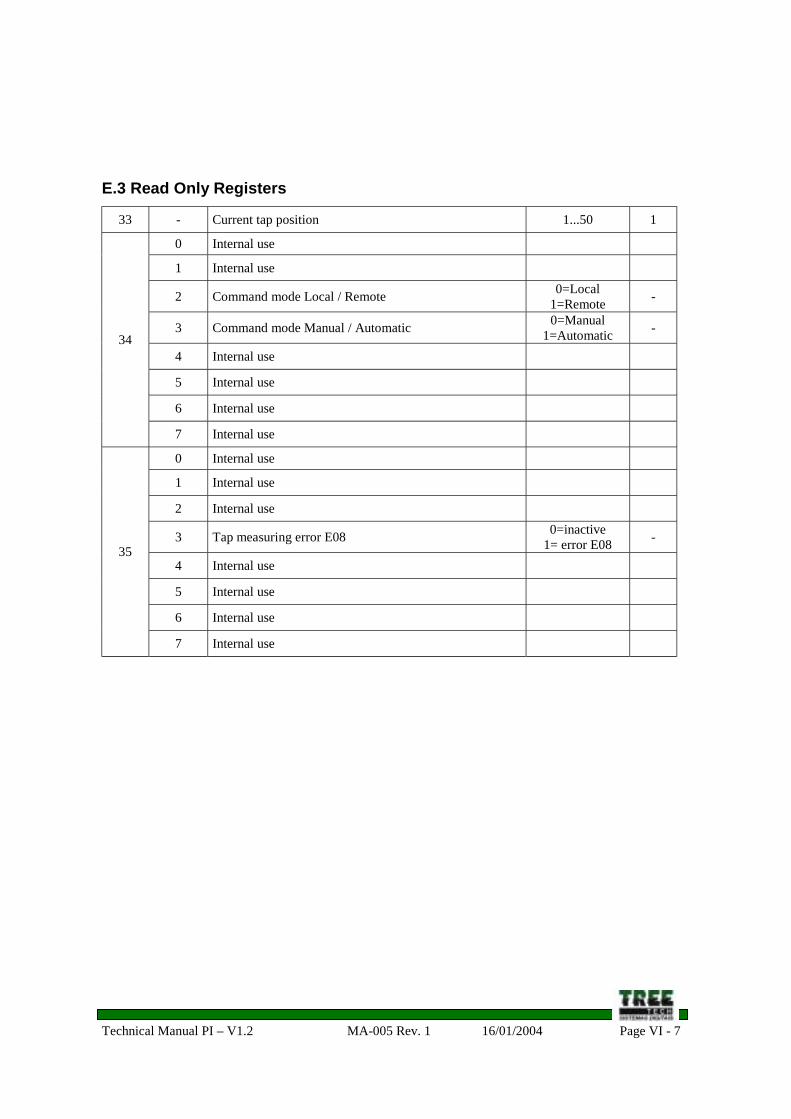
E.3 Read Only Registers VI – 7
Technical Manual PI – V1.2 MA-005 Rev. 1 16/01/2004 Page VI - 2
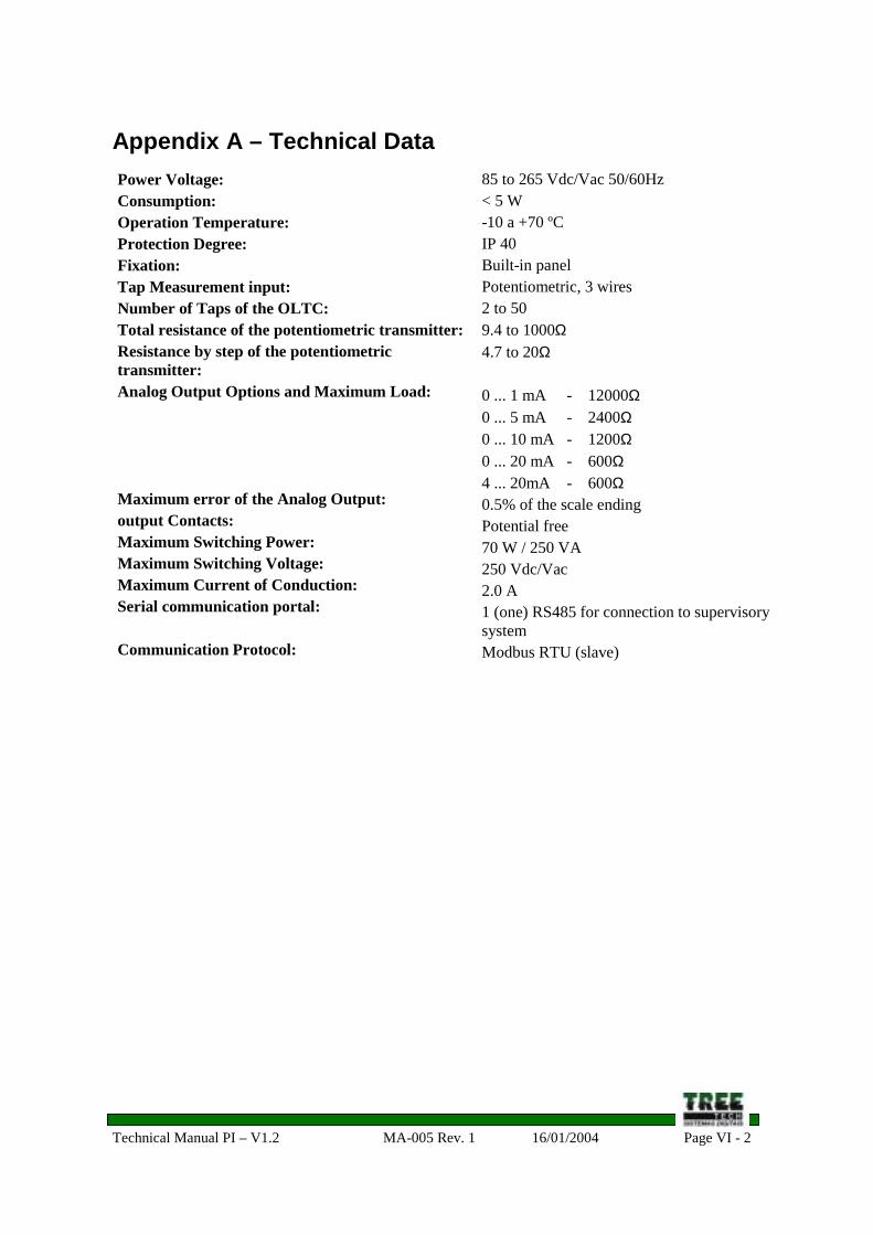
Appendix A – Technical DataPower Voltage:Consumption:Operation Temperature:Protection Degree:Fixation:Tap Measurement input:Number of Taps of the OLTC:Total resistance of the potentiometric transmitter:Resistance by step of the potentiometrictransmitter:Analog Output Options and Maximum Load:
Maximum error of the Analog Output:output Contacts:Maximum Switching Power:Maximum Switching Voltage:Maximum Current of Conduction:Serial communication portal:
Communication Protocol:
85 to 265 Vdc/Vac 50/60Hz< 5 W-10 a +70 ºCIP 40Built-in panelPotentiometric, 3 wires2 to 509.4 to 1000Ω4.7 to 20Ω
0 ... 1 mA - 12000Ω0 ... 5 mA - 2400Ω0 ... 10 mA - 1200Ω0 ... 20 mA - 600Ω4 ... 20mA - 600Ω0.5% of the scale endingPotential free70 W / 250 VA250 Vdc/Vac2.0 A1 (one) RS485 for connection to supervisorysystemModbus RTU (slave)
Technical Manual PI – V1.2 MA-005 Rev. 1 16/01/2004 Page VI - 3
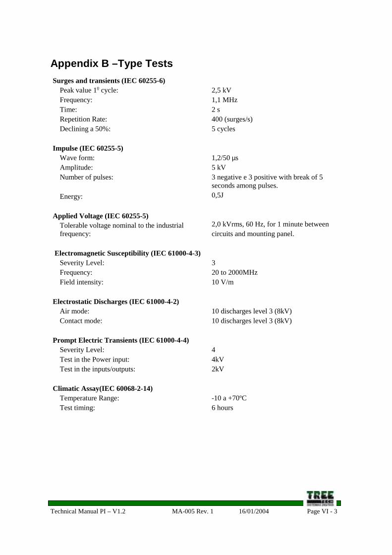
Appendix B –Type TestsSurges and transients (IEC 60255-6)
Peak value 1o cycle:Frequency:Time:Repetition Rate:Declining a 50%:
Impulse (IEC 60255-5)Wave form:Amplitude:Number of pulses:
Energy:
Applied Voltage (IEC 60255-5)Tolerable voltage nominal to the industrialfrequency:
Technical Manual PI – V1.2 MA-005 Rev. 1 16/01/2004 Page VI - 4
Appendix C – Specification for Order
The PI was schemed to allow a universal application, exempting specific datainformation during the equipment purchase. The following selections contribute forits universal application. These selections are performed in the firmware (internalsoftware) of the PI by its front panel (see sub-chapter 8.1):
- Number of tap changer positions: from 2 to 50;
- Tap indication type: simple numerical, bilateral numerical or alphanumerical,with direct or inverted indication and with “neuter” tap that can be selected;
- Resistance by step of the potentiometric transmitter: from 4,7 to 20 ohms;
- Maximum tap change time of the tap changer: from 1 to 100 seconds;
- Current output for tap remote 0-1, 0-5, 0-10, 0-20 or 4-20mA, with bipolaroutput option (-/+);
Thus, during the PI purchase it is not necessary to inform none of the data abovedescribed, because the user parameterizes the device according to its use.Informing that you want to get the PI is enough.
Technical Manual PI – V1.2 MA-005 Rev. 1 16/01/2004 Page VI - 5
Appendix D – Optional Accessories
D.1 Potentiometric Position Transmitter of Magnetic type
The majority of the recent on-load tap changers, and some of the antique ones, issupplied in the factory by potentiometric position transmitter or dry contacts thatallow the creation of the transmitter by means of the adequate step resistorsinstallation.
However, in case of tap changers that do not have any of these alternatives,Treetech can provide potentiometric position transmitters magnetically operated,without mechanical contacts, what makes its installation easy in antique equipmentalready in operation.
Contact us regarding to this equipment supply and to get its installation services.
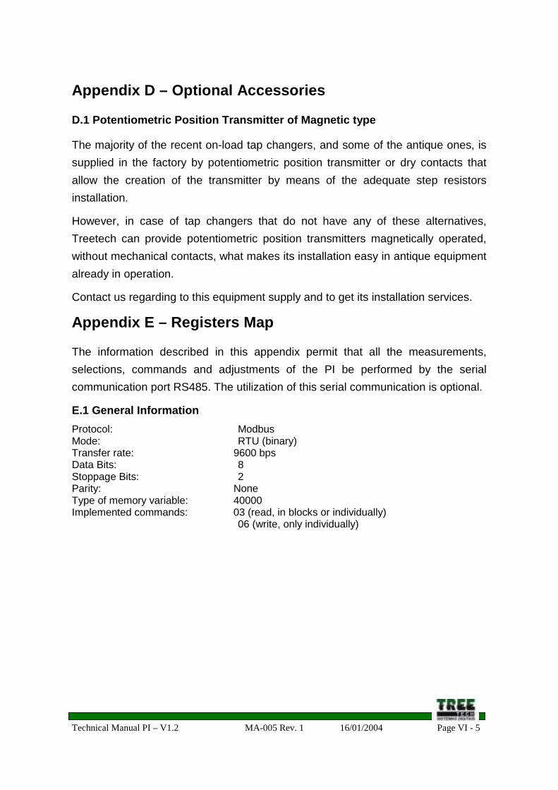
Appendix E – Registers Map
The information described in this appendix permit that all the measurements,selections, commands and adjustments of the PI be performed by the serialcommunication port RS485. The utilization of this serial communication is optional.
E.1 General InformationProtocol: ModbusMode: RTU (binary)Transfer rate: 9600 bpsData Bits: 8Stoppage Bits: 2Parity: NoneType of memory variable: 40000Implemented commands: 03 (read, in blocks or individually)
06 (write, only individually)
Technical Manual PI – V1.2 MA-005 Rev. 1 16/01/2004 Page VI - 6
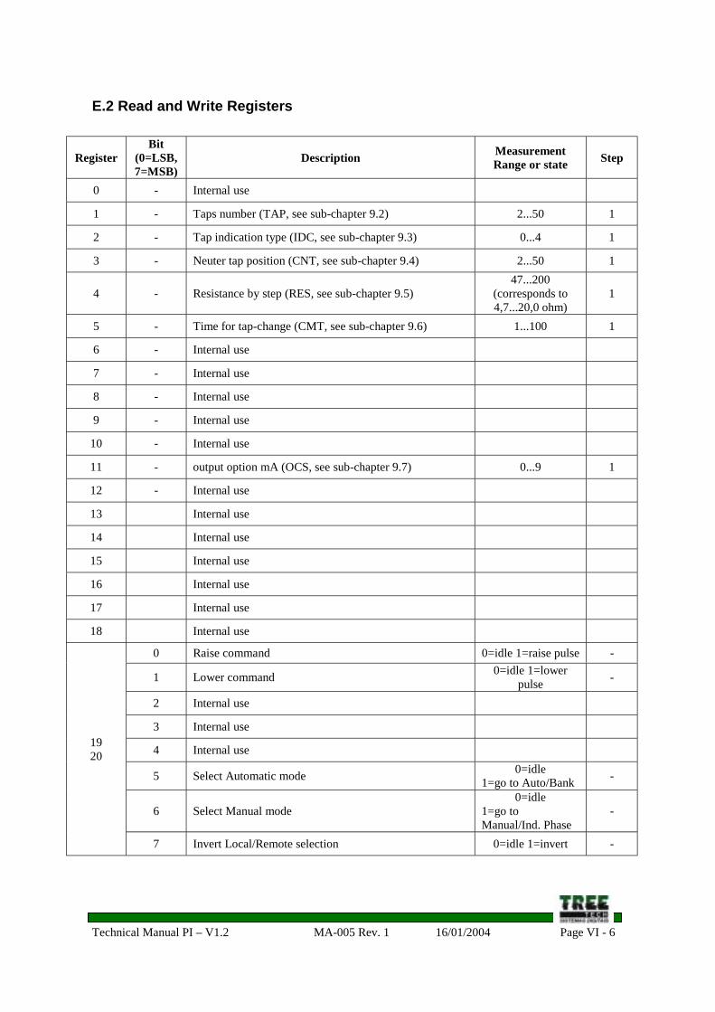
E.2 Read and Write Registers
RegisterBit
(0=LSB,7=MSB)
Description MeasurementRange or state Step
0 - Internal use
1 - Taps number (TAP, see sub-chapter 9.2) 2...50 1
2 - Tap indication type (IDC, see sub-chapter 9.3) 0...4 1
3 - Neuter tap position (CNT, see sub-chapter 9.4) 2...50 1
4 - Resistance by step (RES, see sub-chapter 9.5)47...200
(corresponds to4,7...20,0 ohm)
1
5 - Time for tap-change (CMT, see sub-chapter 9.6) 1...100 1
6 - Internal use
7 - Internal use
8 - Internal use
9 - Internal use
10 - Internal use
11 - output option mA (OCS, see sub-chapter 9.7) 0...9 1
12 - Internal use
13 Internal use
14 Internal use
15 Internal use
16 Internal use
17 Internal use
18 Internal use
0 Raise command 0=idle 1=raise pulse -
1 Lower command 0=idle 1=lowerpulse -
2 Internal use
3 Internal use
4 Internal use
5 Select Automatic mode 0=idle1=go to Auto/Bank -
6 Select Manual mode0=idle
1=go toManual/Ind. Phase
-
1920
7 Invert Local/Remote selection 0=idle 1=invert -
Technical Manual PI – V1.2 MA-005 Rev. 1 16/01/2004 Page VI - 7


![11KV TAP CHANGER TYPE [A] ABS - On Load Gears LOAD GEARS 11KV TAP CHANGER TYPE [A] ABS TECHNICAL DETAILS [A]ABS11 OLTC is air insulated, externally mounted On Load Tap Changer. This](https://static.documents.pub/doc/80x56/5aaeb09e7f8b9adb688ca6f2/11kv-tap-changer-type-a-abs-on-load-load-gears-11kv-tap-changer-type-a-abs.jpg)


