= a INSTRUCTIONS FOR II WESTON MODEL 686 - TYPElOA .True Mutual Conductance Vacuum Tube Analyzer j, II WESTON ELECTRICAL INSTRUMENT CORPORATION NEWARK5, NEW JERSEY,U. S. A. '.2551 3.54 Pri"ted in U.S.A. 1 II 1:1 II II II Ii!!
Transcript
= a
INSTRUCTIONSFOR
II WESTONMODEL 686 - TYPElOA
.True Mutual Conductance
Vacuum Tube Analyzerj,
II
WESTON ELECTRICAL INSTRUMENT CORPORATION
NEWARK5, NEW JERSEY,U. S. A.
'.2551 3.54 Pri"ted in U.S.A.
1
II
1:1
II
II
II
Ii!!
INSTRUCTIONS
FOR
WESTON
MODEL 686 - TYPE lOA
True Mutual Conductance VacuumTube Analyzer
CONTENTS PAGE
Controls, Variable
Control Grid Voltage AdjusteL_mmm m_umm_m4Heater Voltage Adjusterm_uhm_mmum_m__uu__m___AHum mmmmm_u__u__um___m__umm 5, 7 (Step27)
Plate Voltage Adjuster:See "D-C Power Supply Controls"mm u m_5
Screen Voltage Adjuster:See "D-C Power Supply Controls"m_mmm__m_m5
Suppressor Voltage Adjuster:-See "D-C Power Supply Controls"m__m__m__mu__5
D-C Power Supply Controls_m_m_mmmmm m__5Detailed Description of Model 686 Type 10A__3-4-5-6Front Panel View of Model 686 Type 10Am_mmmm__2General Description m m___n__m_m mm_3General Information __nm__mm__h__mum_mm_mmmm_ 10
Gm Readings
Amplifier Tubes __hu mm___mm__u__mnm__mm_m7-8
Inconsistent on Filament Types:See "Hum Control" _mm___mmm_mmu5, 7 (Step 27)
The Model 686 is a complete direct reading TrueMutual Conductance Vacuum Tube Analyzer de-signed to operate from any 105 to 125 or 230 volt50-60 cycle outlet. It has eight mutual conductanceranges with full scale readings of 300, 600, 1500 and3,000 micromhos and also 3,000, 6,000, 15,000 and30,000 micromhos. Instruments are provided for ac-curately measuring all electrode voltages and forreading electrode currents including minute gridcurrents.
Internal power supplies and a signal source provideall necessary potentials to panel controls, whereinadjustments can be made in accordance with meterreadings. Tube sockets for all commercial type re-ceiving tubes are mounted on a removable socketpanel across the top front section of the equipment.These in turn connect through short-test switches topatch cord jacks which are marked with R.M.A. pinnumbers and are used with patch cords for any orall electrode connections. Thus with complete con-nector flexibility and complete voltage control, allkinds of static characteristics can be plotted, in addi-tion to the measurement of Gill under any or all ap-plied potential conditions.
DETAILEDDESCRIPTIONOF EQUIPMENT
THEG./IIMETER: The fan shaped instrument in the topcenter of the main panel is the Gillmeter. The scaleis calibrated in two arcs reading zero to fifteen andzero to thirty and sixty. This meter operates withtwo multiplier switches marked "GM RANGE" and"GM Factor".
The Gill Range switch is used for selecting the300,600, 1500, or 3,000 micromhos range as required,with corresponding grid signal voltages of 1.0, 0.5,0.2, and 0.1 volts respectively. The GIllFactor switchis used to extend the ranges by a factor of ten timesso that ranges of 3,000, 6,000, 15,000 and 30,000 arealso available.
On low mu tubes with low plate resistance, themeter resistance is a reasonable part of the total tubeand tube tester plate circuit impedance; measure-ments on these tubes would be in error unless .thiswas taken into consideration. The compensation ismade automatically for all tubes having a plateresistance above 250 ohms.
On high mu tubes the peak value of the grid signal. voltage should be kept smaller than the dc grid bias
voltage to prevent direct grid conduction. On tubeshaving sharply curved characteristics the grid signal
should be kept small to avoid second-order effects.The low signal voltages available make it possibleto measure all low bias tubes operated and testedas Class A amplifiers.
It is advisable for the operator to select the low-est grid signal voltage that will render reasonablepointer deflection when testing all low bias high mutubes.
Note that a 3,000 micromho range is available witheither a 1 volt signal or a 0.1 volt signal. Use the0.1 volt signal for low bias high mu tubes. The 1 voltsignal is useful for tubes having a-c operated filia-mentary cathodes, where it is desirable to increasethe signal voltage to minimize hum effects.
The a-c grid signal voltage is calibrated on theGill meter to eliminate possible errors due to temper-ature and amplifier gain. If the instrument is readingthe a-c plate current component 2% low because ofthese effects, it will likewise require a signal voltage2 % higher in value to bring the meter to top markon Signal Calibrate. Since the signal voltage ishigher, the GIll indication will also be higher andhence compensation is obtained.
GRID CURRENTMETER:A two range microammeterfor grid current readings is mounted to the left of theGill meter. This instrument has a range of 15-0-15microamperes. Readings down to and including one-half microampere are easily read. The meter is nor-mally shunted to 1500-0-1500 microamperes and isswitched to the low range by manipulation of a mo-mentary toggle switch located to the right of themeter.
The meter is a zero center instrument to indicate
any or all components of grid current resulting fromgas, leakage resistance, or secondary emission. Gridcurrent readings are especially important in segre-gating defective power tubes such as the type 6L6where a limit of 3 microamperes is specified.
In taking grid current readings, the operator willnote that there is a red line on each side of the cen-ter scale zero mark. This red line indicates 15 micro-
. ,
amperes on the 1500 microampere range. If thepointer does not deflect beyond the red line after thetube is heated, then the Microamperes switch can beshifted to the 15 microampere position, and readingstaken on this low range. The instrument is in serieswith the control grid patch cord jack at all times and,therefore, will indicate grid current under all operat-ing conditions.
-3-
I
1
j ELEMENTCURRENTMETER: A four range d-c milliam-meter used to measure cathode, suppressor, screen,or plate current. The Element Current Range switchbelow the instrument serves to select either the 3, 12,60 or 120 milliampere range. The Element Currentswitch directly to the left of the range switch selectsthe electrode in which the current is to be measured.
11
1
!
1
!;.1
J
The Element Current meter has less than 75 milli-volts drop in the electrode circuit to which it is con-nected. The switch is designed so that all other posi-tions are short circuited. This switch may be indexedto any position at any time without effecting read-ings.
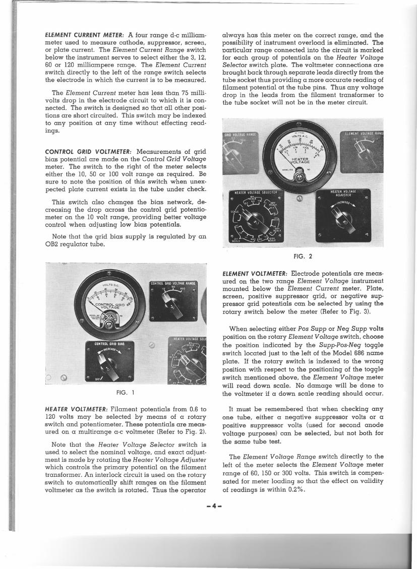
CONTROLGRID VOLTMETER:Measurements of gridbias potential are made on the Control Grid Voltagemeter. The switch to the right of the meter selectseither the 10, 50 or 100 volt range as required. Besure to note the position of this switch when unex-pected plate current exists in the tube under check.
This switch also changes the bias network, de-creasing the drop across the control grid potentio-meter on the 10 volt range, providing better voltagecontrol when adjusting low bias potentials.
Note that the grid bias supply is regulated by anOB2 regulator tube.
I
L
FIG. 1
i,1
i~ij14~1
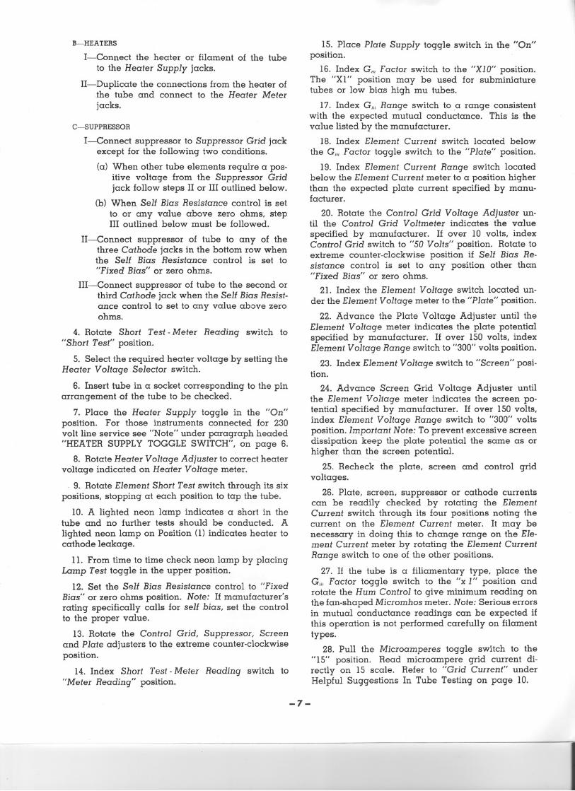
HEATERVOLTMETER:Filament potentials from 0.6 to120 volts may be selected by means of a rotaryswitch and potentiometer. These potentials are meas-ured on a multirange a-c voltmeter (Refer to Fig. 2).
Note that the Heater Voltage Selector switch isused to select the nominal voltage, and exact adjust-ment is made by rotating the Heater Voltage Adjusterwhich controls the primary potential on the filamenttransformer. An interlock circuit is used on the rotaryswitch to automatically shift ranges on the filamentvoltmeter as the switch is rotated. Thus the operator
always has this meter on the correct range, and thepossibility of instrument overload is eliminated. Theparticular range connected into the circuit is markedfor each group of potentials on the Heater VoltageSelector switch plate. The voltmeter connections arebrought back through separate leads directly from thetube socket thus providing a more accurate reading offilament potential at the tube pins. Thus any voltagedrop in the leads from the filament transformer tothe tube socket will not be in the meter circuit.
FIG. 2
ELEMENTVOLTMETER:Electrode potentials are meas-ured on the two range Element Voltage instrumentmounted below the Element Current meter. Plate,screen, positive suppressor grid, or negative sup-pressor grid potentials can be selected by using therotary switch below the meter (Refer to Fig. 3).
When selecting either Pos Supp or Neg Supp voltsposition on the rotary Element Voltage switch, choosethe position indicated by the Supp-Pos-N eg toggleswitch located just to the left of the Model 686 nameplate. If the rotary switch is indexed to the wrongposition with respect to the positioning of the toggleswitch mentioned above, the Element Voltage meterwill read down scale. No damage will be done tothe voltmeter if a down scale reading should occur.
It must be remembered that when checking anyone tube, either a negative suppressor volts or apositive suppressor volts (used for second anodevoltage purposes) can be selected, but not both forthe same tube test.
The Element Voltage Range switch directly to theleft of the meter selects the Element Voltage meterrange of 60, 150 or 300 volts. This switch is compen-sated for meter loading so that the effect on validityof readings is within 0.2%.
-4-
- ------
FIG. 3
D-C POWERSUPPLYCONTROLS:Individual suppressorgrid, screen grid, and plate adjusters are mountedin line across the lower section of the Model 686panel. These are 150 watt or 100 watt vitreous typepotentiometers connected in the d-c supply circuit.These high wattage ratings are used to provide along peripheral length of contact travel, thus givingaccurate potential settings on the tube electrodes. Theelement voltages should be adjusted in the followingorder to prevent damage to the screen and cathodedue to excessive currents: (1) control grid (2) plate(3) screen. All electrode potentials can then be re-adjusted and any changes due to tube loading ofthe power supply can be corrected. The accuracyof the mutual conductance readings depend to agreat extent on the accuracy of these electrode poten-tial adjustments.
SIGNALAMPLITUDEADJUSTER:By effectively chang-ing the signal voltage this potentiometer is used tocompensate for different line voltages. The signalvoltage is checked at full scale on the Gillmeter andany necessary correction is then made with thiscontrol.
To correct for different line voltages the Signalswitch should be placed on the "Ca1." position andthe Signal Amplitude Adjuster rotated to obtain fullscale deflection on the Gm meter.
HUM CONTROL:Filamentary tube types require anaccurate electrical center tap on the filament forcorrect Gm readings, and it is the purpose of thiscontrol to provide such an adjustment. On heatervoltage switch positions 12.5 volts and above, theHum Control is disconnected to prevent excessiveheat dissipation.
After the tube is in position and all electrodepotentials have been adjusted to the specified val-ues, the Gill Factor toggle switch to the right of theGillmeter should be set to the "x 1" position and theHum Control set for a minimum or zero reading on
the Gill meter. (Serious errors in mutual conductance
readings can be expected if this operation is not per-formed carefullyJ
SELFBIAS RESISTANCECONTROL:The Model 686 isequipped with a Self Bias Resistance control mountedon the left side of the top panel section. This controlprovides for checking certain tube types such as the6I4, 6I6 and 1231 where self bias is definitely speci-fied by the manufacturer. These tubes tend to drawgrid current or are unstable under equivalent fixedbias conditions, thus causing errors in Gm readings.
The control may be varied from 0 to 700 ohms,and to prevent degeneration the unit is by-passedby a 1,000 m.f., 50 volt condenser. When checkingthe normal fixed bias types this control must be setto zero (0) but on those types requiring self bias theControl Grid Voltage Adjuster must be set in themost counter-clockwise position. This procedure isnecessary to prevent fixed bias from being appliedin addition to the self bias.
To prevent damage to the 1,000 microfarad con-denser, a simple calculation should be made to seethat the product of the expected cathode current,and the resistance in the self bias circuit does notexceed 50 volts: V == 1x R x .001
Where V == Voltage appearing across 1,000microfarad condenser.
I == Expected cathode current in mill-amperes.
R ==Resistance selected by Self Biasswitch position.
SHORTTEST-METERREADINGAND ELEMENTSHORTTESTSWITCHES:The Short Test-Meter Reading andElement Short Test switches mounted on the rightside of the top panel section provide the necessarymeans for short checking tubes with a d-c potential.Tubes, having a filament or heater, may be shortchecked, either hot or cold. The Short Test-MeterReading switch disconnects the d-c potential andmeters from the tube elements and connects a smalld-c power supply and a neon lamp into a group ofcircuits controlled by the Element Short Test switch.This switch segregates the element to be shortchecked, leaving all the other elements tied together.
The filament or heaters should be at normal op-erating temperature when hot short checking, andthe Short Test-Meter Reading switch should be in-dexed to "Short Test" position. The Element ShortTest switch is then rotated through its six positions,stopping at each position to tap the tube.
If the patch cords have been connected so as touse both PI = Plate 1 and Pz = Plate 2, index thePlate 1 - Plate 2 toggle switch located on the upperright top panel section to its other position and rotatethe Element Short Test switch through its six positionsagain. A slight flicker of the neon lamp betweenpositions on the Element Short Test switch does notindicate a short in the tube.
-5-
p
HEATERSUPPLYTOGGLESWITCH:Located at the bot-tom left side of the panel with its associated greenjewel pilot lamp, this toggle switch disconnects thedevice completely from the line supply when in-dexed to the "Off" position. When in the "On" posi-tion, the heater transformer is energized and the linesupply voltage is delivered to the Plate SupplyToggle Switch. After making the heater connections,the tube can be warming up while the operator iscompleting the patching operation by indexing theHeater Supply toggle switch to the "On" position.
The "Plate Supply" toggle is shorted out on 230 voltservice, therefore, use the "Line Switch" as the "On-Off" switch for the entire device.
PLATESUPPLYTOGGLESWITCH:This switch operatesall of the internal d-c power sources and is inopera-tive if the Heater Supply toggle is in the "Off" posi-tion. The Plate Supply toggle should always be inthe "Off" position when the operator is changing orremoving patch cords.
SIGNALCALIBRATETOGGLESWITCH:To the right ofthe Heater Supply toggle is a momentary type SignalCaI. toggle switch. A change in power line voltage,of course, will affect the grid signal and hence itbecomes necessary to check this potential just beforetaking Gmreadings. Indexing the Signal Cal. toggleto the "CaI." position places the grid signal directlyacross the Gill meter. Regardless of Gm range se-lected, the Gm meter must indicate top mark on thistest. If it does not, the Signal Amplitude Adjustershould be rotated until top mark is obtained.
Gill READING TOGGLESWITCH: This switch is locatedto the left of the Plate Supply switch and is of themomentary type. It is used to apply the signal volt-age when the operator is ready to take a Gm read-ing.
SUPPRESSORPOSNEGTOGGLESWITCH:The purposeof this toggle is to allow the operator to select eithera negative potential for suppressor, or a positivepotential for tubes requiring a second anode voltagesuch as the oscillator plate in a penta grid converter.It must be kept in mind that while checking a giventube only one or the other potential may be used.No occasion will arise requiring both a negativesuppressor potential and a second anode positivepotential, because in such cases, the suppressor ofthe tube is always connected directly to cathode.
To obtain negative suppressor volts index thistoggle, located just to the left of the name plate atthe bottom of the panel, to the NEG position. Tomeasure the negative potential rotate the ElementVolts switch to the "Neg Supp" position.
LAMPTESTTOGGLESWITCH:Located to the left of therotary Plate I - Plate 2 switch, this toggle providesa ready means for checking the neon lamp. If atube shows no short and there is some doubt as to
the condition of the neon lamp, lift the toggle to itsupper position and if it does not glow replace witha new lamp.
OPERATIONSTEP-BY-STEPTESTING PROCEDURE
GENERAL:Read the paper tag on the f!ont panel ofthe instrument. Remove the back cover and insertthe 5U4-G rectifier in the octal socket. Ascertainwhether the 3A4 tube is in place by removing theshield from the miniature socket. Check to see thatthe proper miniature tubes are in their respectiveshielded sockets. Screw the neon lamp in the socketlocated above the Lamp Test toggle switch. The linecord can then be brought to the outside of the caseand the back cover replaced.
A toggle switch has been incorporated to facilitatechange over from 115 volt to 230 volt a-c operation.
This switch is located on the shelf jnside the devicebetween the 8 mfd. condenser and the small signal-short check transformer.
The toggle is normally set for 115 volt operation.For 230 volt operation set the switch as indicatedby adjacent markings.
The Plate Supply toggle is shorted out on 230 voltservice, therefore, use the "Line Switch" as the "On-Off" switch for the entire device.
The instrument is now ready for use and theStep-by-Step Procedure outlined below should beread carefully before attempting to check any tubes.It is suggested that a type 6C4 or any indirectlyheated triode be used to acquaint the operator ofthis device with the various controls and theirfunctions.
AMPLIFIERTUBES:
1. Plug the line cord into a power source havinga frequency of 50-60 cycles and voltage betwee.n105-125.. Refer to preceding paragraph for 230 voltlines.
2. Place Heater Supply and Plate Supply toggleswitches in "Off" position.
3. Patch the jumper leads in accordance with thetube base diagram of the tube to be checked follow-ing the specific procedures for Cathode, Heater andSuppressor connections as follows:
A-CATHODE
I-Connect cathode of the tube to any of thethree Cathode jacks in the bottom row whenthe Self Bias Resistance control is set to"Fixed Bias."
II-Connect the tube cathode to the second orthird Cathode jack if Self Bias Resistancecontrol is set to any value above zero ohms.
-6-
B-HEATERS
I-Connect the heater or filament of the tubeto the Heater Supply jacks.
II-Duplicate the connections from the heater oflhe tube and connect to the Heater Meterjacks.
C-SUPPRESSOR
I-Connect suppressor to Suppressor Grid jackexcept for the following two conditions.
(a) When other tube elements require a pos-itive voltage from the Suppressor Gridjack follow steps II or III outlined below.
(b) When Self Bias Resistance control is setto or any value above zero ohms, stepIII outlined below must be followed.
II-Connect suppressor of tube to any of thethree Cathode jacks in the bottom row whenthe Self Bias Resistance control is set to"Fixed Bias" or zero ohms.
III-Connect suppressor of tube to the second orthird Cathode jack when the Self Bias Resist-ance control to set to any value above zeroohms.
4. Rotate Short Test -Meter Reading switch to"Short Test" position.
5. Select the required heater voltage by setting theHeater Voltage Selector switch.
6. Insert tube in a socket corresponding to the pinarrangement of the tube to be checked.
7. Place the Heater Supply toggle in the "On"position. For those instruments connected for 230volt line service see "Note" under paragraph headed"HEATER SUPPLY TOGGLE SWITCH", on page 6.
8. Rotate Heater Voltage Adjuster to correct heatervoltage indicated on Heater Voltage meter.
. 9. Rotate Element Short Test switch through its sixpositions, stopping at each position to tap the tube.
10. A lighted neon lamp indicates a short in thetube and no further tests should be conducted. Alighted neon lamp on Position (1) indicates heater tocathode leakage.
11. From time to time check neon lamp by placingLamp Test toggle in the upper position.
12. Set the Self Bias Resistance control to "FixedBias" or zero ohms position. Note: If manufacturer'srating specifically calls for self bias, set the controlto the proper value.
13. Rotate the Control Grid, Suppressor, Screenand Plate adjusters to the extreme counter-clockwiseposition.
14. Index Short Test -Meter Reading switch to"Meter Reading" position.
IS. Place Plate Supply toggle switch in the "On"position. .
16. Index Gill Factor switch to the "XIO" position.The "Xl" position may be used for subminiaturetubes or low bias high mu tubes.
17. Index Gill Range switch to .a range consistentwith the expected mutual conductance. This is thevalue listed by the manufacturer.
18. Index Element Current switch located belowthe Gill Factor toggle switch to the "Plate" position.
19. Index Element Current Range switch locatedbelow the Element Current meter to a position higherthan the expected plate current specified by manu-facturer.
20. Rotate the Control Grid VoItage Adjuster un-til the Control Grid Voltmeter indicates the valuespecified by manufacturer. If over 10 volts, indexControl Grid switch to "50 Volts" position. Rotate toextreme counter-clockwise position if Self Bias Re-sistance control is set to any position other than"Fixed Bias" or zero ohms.
21. Index the Element Voltage switch located un-der the Element Voltage meter to the "Plate" position.
22. Advance the Plate Voltage Adjuster until theElement Voltage meter indicates the plate potentialspecified by manufacturer. If over 150 volts, indexElement Voltage Range switch to "300" volts position.
23. Index Element Voltage switch to "Screen" posi-tion.
24. Advance Screen Grid Voltage Adjuster untilthe Element Voltage meter indicates. the screen po-tential specified by manufacturer. If over 150 volts,index Element Voltage Range switch to "300" voltsposition. Important Note: To prevent excessive screendissipation keep the plate potential the same as orhigher than the screen potential.
25. Recheck the plate, screen and control gridvoltages.
26. Plate, screen, suppressor or cathode currentscan be readily checked by rotating the ElementCurrent switch through its four positions noting thecurrent on the Element Current meter. It may benecessary in doing this to change range on the Ele-ment Current meter by rotating the Element CurrentRange switch to one of the other positions.
27. If the tube is a filiamentary type, place theGill Factor toggle switch to the "x 1" position androtate the Hum Control to give minimum reading onthe fan-shaped Micromhos meter. Note: Serious errorsin mutual conductance readings can be expected ifthis operation is not performed carefully on filamenttypes.
28. Pull the Microamperes toggle switch to the"IS" position. Read microampere grid current di-rectly on 15 scale. Refer to "Grid Current" underHelpful Suggestions In Tube Testing on page 10.
-7-
29. Lift the Signal toggle switch to the "Cal." posi-tion and rotate the Signal Amplitude Adjuster tobring the Micromhos meter to exactly top mark.
30. Release Signal toggle switch.
31. To take the Gm reading, index the "Gill" tog-gle switch to the "Reading" position and read theMicromhos meter. Read the scale which correspondsto the "Gm Range" switch setting and multiply by anadded factor of 10 if the "Gm Factor" switch is set tothe "XI0" position.
RECTIFIERTUBES:
32. Patch jumper leads as in steps "3 and 3-(B)."If rectifier has double plates, patch one of the platesto the Plate 1 jack and the other to Plate 2 jack.
33. Follow steps 4-10 inclusive. If double rectifierplates have been patched as above, short check thetube as in step 9 indexing the Plate toggle switch toboth "Plate I" and "Plate 2" positions.
34. Follow steps 12-15 inclusive.
35. Set G.mFactor switch to "xl0."
36. Turn "Signal Amplitude" adjuster to zero. Note:If steps 35 and 36 are not followed, the emissionmeasurements will not be in error. However, follow-ing these two steps reduces the Gm meter sensitivity.
37. Index Element Current switch to "Plate" posi-tion.
38. Index Element Current Range switch to "120"position.
39. Index Element Volts switch to "60."
40. Place Plate Supply toggle switch in the "On"position.
41. Advance the Plate Voltage Adjuster carefullyuntil the Element Current meter indicates the current
listed in the Tube Data Chart suppli~d separately.42. Reject the tube as bad if the plate voltage re-
quired to give the specified current is greater thanthat shown in the Tube Data Chart su,Pplied sep-arately.
43. Repeat the emission check on the second platein the same manner indexing the Plate 1 - Plate 2toggle to its other position.
44. If the two plates have materially different emis-sion readings the tube should be rejected.
DIODE DETECTORS:
45. Patch jumpers as in step 32 and in additionconnect all other elements to cathode.
46. Follow steps 33-44 inclusive, except that instep 38 the Element Current Range switch should beindexed to the "3" position. Note: The 0.8 MA. limit at10 volts maximum is usually considered satisfactory,however, diodes normally pass considerably greatercurrent, some going as high as 2 or 3 MA.
CONVERTERAND MIXER-OSCILLATOR TYPES:
47. Patch the jumper leads in accordance with theinformation in Tube Data Chart supplied separately.
A-The figure in parenthesis in the Tube DataCharts refers to the pin connection. Example:A type lA7-GT shows the figure (3) and (6) inparenthesis in the column headed Plate Volts.Hence pins 3 and 6 are connected togetherand patched to the Plate 1 jack by means ofthe jumper leads.
B-The letter (C) in parenthesis denotes Grid Cap.Example: A type lA7-GT shows the figure (5)and the letter (C) in parenthesis in the columnheaded Control Grid VoHs. Hence pin 5 andthe tube's grid cap are connected together andpatched to the Control Grid jack by means ofthe jumper leads.
48. Follow steps 4 through 31 omitting any re-marks concerning "manufacturer's specifications"and substituting "value specified in the Tube DataChart supplied separately.
49. Reject tube when the mutual conductance indi-cation is below that value specified in the columnheaded "Life End."
THYRATRONTUBES:
Thyratrons such as the 2050 and 2051 can bechecked in any type Model 686. The step-by-stepprocedure given below is for the tube type 2050.Checking other thyratrons involves the same pro-cedure but it must be kept in mind that the tubesshould be of a type similar to the 2050 and 2051.
1. Make connections by use of patch cords inaccordance with the base diagram except thata 100,000 ohm 1/2 watt resistor should be in-serted in the grid lead to pin 5. Number 2 gridshould be connected directly to cathode.
2. Set G./IIFactor switch to "x 10".
3. Turn Signal Amplitude Adjuster to zero.
4. Set Element Current Range switch to "120" milli-amperes.
5. Set Element Current switch to "Plate" posi-tion.
6. Before inserting the tube apply the followingelement voltages: . .
7. Insert tube, readjust filament voltage and allowto heat for at least 30 seconds.
8. Reduce the grid bias carefully until the thyra-tron fires. .
-8-
--
9. LIMITS: If the tube fires between - 3 and - 1volts on the grid, the tube is within manufac-turing limits for both end point and variationin new tubes.
Note: Once the tube fires, the grid loses control.If it should be necessary to repeat the test, in-crease the grid bias to - 10 volts and decreasethe plate voltage to zero, and then reset it to212 volts and repeat the above procedure.
The plate current for tubes 2050 and 2051should not exceed 100 milliamperes and 75milliamperes respectively. If it does, reducethe plate voltage slightly to bring it within thesevalues.
Note also that when the thyratron fires theplate voltage will drop to about 7-1/2 volts.This is normal.
For low current thyratrons, a lower initialplate voltage should be used, or a current lim-iting resistor inserted in the plate patch cordlead.
VOLTAGE REGULATORS:
The Model 686 can check voltage regulator tubessimilar to the 874 and VR-150-30 types. The pro-cedure outlined below is for checking the 874 type.
1. Make connections by use of patch cords inaccordance with the base diagram. In the caseof the 874, Pin 1 is the cathode and Pin 3 isthe anode or plate.
2. Set Gm Factor switch to "x 10".
3. Turn "Signal Amplitude" control down to zero.
4. Set Element Current Range switch to "120" milli-amperes.
5. Set Element Current switch to "Plate" posi-tion.
6. Increase the plate voltage until conduction be-gins. This should be at approximately 115 voltsfor the type 874. (For other voltage regulatorsrefer to manufacturer's ratings).
7. To check the regulating characteristics varythe plate voltage to produce anode currents be-tween 10 and 50 milliamperes maximum. (Forother voltage regulators see manufacturer'sratings.)
Note: The voltage applied to produce currentsbetween 10 and 50 milliamperes should bewithin the limits indicated by the man ufac-turer's ratings. In the case of the 874 the voltageafter conduction should not vary more than 7when the current is varied from 10 to 50 milli-amperes.
THEORY OF OPERATION
Essentially the Model 686 is a low impedancepower supply metered for potentials and currentsand provided with a means of introducing an a-csignal into the grid bias line and measuring the a-ccomponent in the plate circuit.
The incoming a-c line energizes the d-c powersupply, the heater voltage supply and the a-c gridsignal transformer. The filament transformer controlis located in the primary leads thus providing properadjustment to take care of varying line voltage con-ditions. A rotary switch selects secondary taps togive the necessary heater voltages for all tubes.
The d-c power supply delivers potentials to theplate, screen and suppressor controls. Followingthese controls the potentials are metered and the cir-cuit is so arranged that the element milliammetercan be placed in each of the lines. A separate reg-ulated power supply develops the voltage for gridbias. This potential is likewise controlled by a poten-tiometer. A separate voltmeter is used to measurethis potential and a microammeter is placed in thecircuit to detect the presence of grid current.
The a-c grid signal winding together with a signalvoltage divider is placed in series with the controlgrid circuit to the tube. The proper signal voltagesare selected by the Gm Range switch which is con-nected to the signal voltage divider. The injectionof the a-c grid signal into the grid bias circuit is afunction performed by the Gm Reading toggle switch.
The Gm meter is an amplifier-rectifier type a-cinstrument which is connected to the plate circuit formeasuring the a-c component of plate current.
The element potentials are fed to a multi-circuitShort Test-Meter Reading switch. This switch pro-vides the necessary circuit connections so that tubeelements may be either short checked by means ofthe Element Short Test switch or energized by thepotentials from the power supply.
The a-c grid signal transformer has a separatewinding feeding a type 3A4 tube which supplies thenecessary d-c voltage for high sensitivity short check.
The Hum Control is simply a potentiometer placedacross the filament winding to provide the necessarybalance on the filament return when checking thesetypes. This is to prevent an additional signal (whichmay either add to or subtract from the true grid sig-nal) from appearing in the grid circuit causing amodification in the a-c plate current component. TheHurn Control is switched out of the circuit on heatervoltages above 10.
In checking a tube, the d-c potentials are appliedto the tube through the various controls. The a-c gridsignal is applied in series with the grid bias voltage,and is measured by switching the Gm meter to "Sig-nal Cal." and held to a fixed value by rotating theSignal Amplitude Adjuster. To measure a-c compo-
-9-
nent of plate current, the Gill meter is switched tothe "Gm Reading" position. Inasmuch as the valueof the grid signal and the a-c component of platecurrent are known, the mutual conductance is the
ratio of the two. Since the ratio 2~: == G1l1 consistsof one known value and one measured quantity, thescale can be calibrated directly in micromhos.
GENERAL INFORMATION
INSTRUCTIONBOOK: This edition of the instructionbook applies to Model 686, Type lOA.
Any questions concerning a special application,the use, maintenance or repair of these modelsshould be addressed to Weston Electrical InstrumentCorporation, giving all the information listed on page11 under paragraph ORDERING INFORMATION.
TUBEMANUALS: It is advisable for the operator ofthis device to have at his disposal a tube manualwhich can be obtained from any of the tube manu-facturers. A manual facilitates the measurements oftubes at potentials not normally listed in the manu-facturer's specifications.
For example, if the mutual conductance of the 6C8were to be measured at 150 volts and -I ¥2 voltsbias a glance at the Ep-Ip curves would show thaton the vertical line corresponding to 150 volts achange in plate current of 1.6 milliamperes wouldresult with a grid bias change of -1 to -2 volts.The expected mutual conductance, therefore wouldbe approximately 1600 micromhos, this value beingobtained by dividing plate current change in milliam-peres by the grid bias change in volts and multiply-ing by 1,000. Computing the approximate Gm to beexpected as explained above sometimes eliminatesan incorrect reading due to improper testing of thetube.
TUBEDATA CHARTS:Tube Data Charts, supplied sep-arately, list the manufacturer's nominal ratings forthe element potentials, mutual conductance, ampli-fication factor, and the tube base diagram number.These charts will in most cases handle all of the tubesthat will be checked, and should be used as a quickreference supplement to the tube manual. Tubes notlisted in the charts can be checked if the basing andelement potentials of the tube are known.
REJECTLIMITS:The reject limits listed should be con-sidered as nominal limits only. It is possible that incertain special applications it will be necessary toreject a tube when its G1l1has fallen to possibly only75 or 80% of its nominal value. In other cases areduction of 60% in the G1l1would have no adverseeffect on the operation of the circuit. If an end pointfigure or an end point range is specified by thetube manufacturer, the operator should be guidedaccordingly.
If it is not known what reduction in Gm'is allow-able, the limits in percent of normal listed below aresuggested as the proper end points for use in gen-eral electronic equipment:
RF, IF, and Pentode Voltage Amplifiers 65%
General Purpose and high mu Triodesm___50%
Power Output Types m m 50%
Converters and Mixers(Refer to Tube Data Chart)
Rectifiers (Refer to Tube Data Chart)
Diode Detectors (Refer to page 8, Step 46.)
D-C FILAMENTSUPPLY:In certain applications it maybe desirable to measure the mutual conductance ofa filamentary type using d-c voltage instead of ana-c source to energize the filmaent. In such casesindex the Heater Voltage switch to zero position, runjumper leads from the d-c filament supply source tothe proper numbered pin jacks in the top two rows.Connect an additional lead from the negative fila-ment supply to the second or third Cathode pin jack.A separate d-c instrument will be required to meas-ure the filament voltage and should be connectedinto the two pin jacks in the top two rows corre-sponding to the filament connections.
HELPFULSUGGESTIONSIN TUBE TESTING
GRIDCURRENT:In using the Model 686 care shouldbe exercised to see that the grid current in micro-amperes indicated on the Grid Current meter doesnot exceed three to four microamperes. This valuechanges somewhat between tube types, but theabove value can be assumed in general, to besatisfactory. Excessive grid current will cause anerror in the Gill readings and it is advisable that alimit of 4 microampere3 be strictly adhered to andthat some means of eliminating this condition shouldbe tried as outlined below.
If the Grid Current meter deflects to the left ofzero the tube is either gassy or the element potentialsapplied are not correct. Check the manufacturer'sspecification and note whether the proper potentialshave been applied. If the potentials are correct andthe meter indicates 4 microamperes or more to theleft of zero the tube should be rejected.
If the Grid Current meter indicates to the right ofthe zero with the correct potentials applied, the tubeis oscillating. This condition must be eliminated be-fore accurate Gillindications can be obtained. Usuallya 15 to 20 ohm resistor placed in some one of theelectrode leads, except filament or cathode, willeliminate the tendency to oscillate.
There are some tubes requiring low bias and if thesignal voltage applied is too high, grid rectificationwill cause the Grid Current meter to indicate to theright of zero. This condition can be readily detectedby noting the increase in Grid Current meter deflec-
-10-
---
tion when the Grid Signal toggle switch is indexedto the "On" position and the Microamperes toggleswitch is indexed to the "IS" position. To correctthis select the next higher Gm range, as this willreduce the grid signal.
Any attempt to check certain tubes under FixedBias conditions that should be checked under Self-Bias conditions, usually results in tube oscillationor instability.
The Grid Current meter will also indicate to theright of zero when the plate supply and grid biaspotentials are extremely low or zero.
INCONSISTENTG.mREADINGSON fiLAMENTARYTYPETUBES:Inconsistent Gmreadings on filamentary typetubes is caused by improper setting of the Hum Con-trol. It is recommended that Step 7:7 in the Step-by-Step Procedure on page 7 be performed morecarefully. The operator might find it helpful to tem-porarily set the G.mFactor range switch to the Xlposition to obtain the maximum sensitivity whenperforming this operation.
VERYLOW ORNO G.mREADING:Assuming the elec-trode potentials to be correctly applied and adjustedthe operator may find that the Gm reading is zero.This may be caused by having the"Signal Ampli-tude" adjuster turned down to zero.
If the Self Bias Resistance control is set a valuehigher than zero ohms and the grid bias voltmetercontrol has not been returned to the extreme counter-clockwise position, the total grid bias applied to thetube will be that indicated by the Control Grid Volt-meter plus the bias developed in the self bias resis-tor. This condition would cause the plate current tobe very low and the Gmto be either very low or zero.
Other factors causing low Gm readings are de-scribed in the section on Maintenance.
PRECAUTIONS
Don't Attempt to Test a tube unless it has been foundcleared in the short test.
Don't attempt to patch the circuit unless the PlateSupply toggle switch is in the "Off" position.
Don't Insert a Tube until you are certain that theHeater Voltage switch is set to the correct valuefor that tube. Check with the Tube Data Chart.
Don't Insert a Tube in the Test Circuit Unless All Volt-age Adjusters Are Rotated to the "Off" Position.This may be waived if testing a group of identicaltubes.
Don't Test Rectifiers beyond their maximum currentcarrying capacity.
Don't apply more than 10 volts to diode detectors ortheir emission may be lost.
Don't Fail to Bring Up the Grid Voltage First, thePlate Voltage Second and the Screen VoltageThird, otherwise the cathode or the screen maybe damaged. .
Don't fail to completely Shut Off the device whentesting is completed.
MAINTENANCE
RECTifiERTUBES:It is recommended that the severalcomponents in the device be checked at two yearintervals so that the equipment is maintained in acompletely satisfactory operating condition.
If the power supply will not deliver 300 volts at100 milliamperes at a measured line voltage of 120,the 5U4-G rectifier is failing and should be replaced.A 6L6 or a type 2A3 tube may be used as a load byapplying 300 volts to the plate and lowering the gridbias from the specified value until the element cur-rent meter indicates 100 milliamperes. This will pro-vide a convenient load for the power supply forchecking the rectifier.
Each of the small miniature type tubes, 3A4, OB2,and 6X4, can be checked by removing it from itssocket and testing in the Model 686.
ELECTROLYTiC CONDENSERS:Every two to threeyears the electrolytic condensers in the Model 686should be checked with a capacity analyzer to deter-mine whether they are in a satisfactory condition. Itis necessary to remove the back cover to check thesecondensers.
The low voltage 1,000 microfarad condenser islocated in a clip near the right hand section ofthe top panel when looking at the instrument fromthe back. The capacitance of this unit should not beallowed to fall below 500 microfarads as it willcause Gm indications to be very low under self biasconditions.
The 40 microfarad 450 W.V. electrolytic conden-sers located in clips under the shelf at the left sidewhen looking at the back of the instrument, shouldnot be allowed to fall to a value below 30 micro-farads, nor have a power factor exceeding 30 percent.
High Gm indications can be expected on tubeswhen the capacity of the 40 microfarad condensersfall below 30 microfarads.
ORDERING INFORMATION
If an occasion should ever arise requiring theordering of parts, be sure to give the Model Num-ber, Type Number, Serial Number, Voltage and Fre-quency Ratings.
A description and location of the part in theequipment should be as complete as possible.
Address all inquiries to Weston Electrical Instru-ment Gorporation, 614 Frelinghuysen Avenue, New-ark 5, New Jersey.