Force Eccentricities in Load Bearing Masonry Walls S. SAHLIN Professor, Royal Institute of Technology, Stockholm, S"eden Sammandrag Olika teorier for berakning av vaggars utbojning jamfors . Andvinkelandringen hos vaggen jamfores med andvinkelandringen hos plattan som vilar pã vaggen och med vinkelandringen i knutpunkten. Andvinkelandring och vinkelandring i knutpunkten ar avgorande storheter for berakning av kraftexcentriciteten i vaggen . Forsoks- resultatar fãtaliga. Abstract Oifferent theories af wall deflection are reviewed and compared. The magnitudes of end rotations are compared and related to the end rotation of the slab resting on the wall and to the joint yieldinÇ). End rotations and joint yielding are deci- sive factors for estimating the force eccentr;c;ties in the walls. Data from tests are scarce. 896
Transcript
Force Eccentricities in Load Bearing Masonry Walls
S. SAHLIN Professor, Royal Institute of Technology, Stockholm, S"eden
Sammandrag
Olika teorier for berakning av vaggars utbojning jamfors . Andvinkelandringen hos vaggen jamfores med andvinkelandringen hos pla ttan som vilar pã vaggen och med vinkelandringen i knutpunkten. Andvinkelandring och vinkelandring i knutpunkten ar avgorande storheter for berakning av kraftexcentriciteten i vaggen . Forsoksresultatar fãtaliga.
Abstract
Oifferent theories af wall deflection are reviewed and compared. The magnitudes of end rotations are compared and related to the end rotation of the slab resting on the wall and to the joint yieldinÇ). End rotations and joint yielding are decisive factors for estimating the force eccentr;c;ties in the walls. Data from tests are scarce.
896
Simp1ified bui1ding structure with load-bearing wa lls.
Ãh[
, "
A
q
Jh / "
In bui1dings with loadbearing masonry wa11s the externa1 wa11s have the 1argest force eccentricities. The external "/a115 are normal1y bent in S- shape with an inf1exion point at about mid -height. Fig. 1. A rea l bui1ding has of course interna1 wal1s crosswal1s and 50 on.
The eccentricity depends upon several parameters: Slab stiffness, wal1 stiffness, joint behaviour, axial load magnitude, slab span and wal1 height.
The condition that determines the eccentricity ;$ the geometrical relation
(1)
where ~v is the end rotation of the wal1 at the joint, e is the joint deformation due to cracklng and/or plastification in the joint, and ~h is the slab end rotation.
Sometimes the joint rotation e can be assumed to be
e o for M
' "" } (2)
O < e < eult for M I~p~
See figure 2.
897
I
WaU
M
f--- ( J Joint
Type of joint and idea li zed ralationsh i p between applied moment M and angle of rotation a in a joint. 8ult equals ul ti mate rotation . Mp~ equals "yie1ding" moment o
We wi11 now turn to the determination af~) ~v and e more in deta i1.
Def l ection of Wa l l
We consider a load-carrying structure of t he type shown i n Fig. 1. The loads q produce bending moments and norma l forces acting on the wa1 1s. A feature which is common to a11 storeys is the fact that the eccent r; ci ties of the normal force in a wa ll are opposite in direction at the top and bottom ends of the wall. The typical case of loading represented in Fig . 3, is obtained when the wall is onestarey high.
In arder to ca lcul ate the mome nt distribution in the l oad-carrying structure shown in Fig . 1, it is necessary to compute t he angle of rotation ~v of the wall as ·a function of a load whic h is applied 50 that its eccentricities are opposite in di rection at the top and bottom ends of the wall. This calculation is comp licated by the circumstance that the wa ll has little ar no tensile strength .
Fi g . 3 - General represen- - - tation of l oads and
deformations in the case of a wal 1 is one-storey high .
898
p
• I -
I I I I I I , I /. I I , I >h I I \ . I .1 I
I \. I I .1 I I
d-l
p
Fig. 3a - Wall subjec ted to eccentric compres-sion; the part Df the wall comprised between the floor slab and the point Df inflection.
I I I
Stress and strain block I \ I crQc~e I \ I ar I-"-' I
É_~,tD5.N=:::j : \1 -,- -- -i h
I' I II
t • I I I I
~---~-----~ I
d I si. I 2' I 2 I ,
1.0
0 .8
0.0 C
0.4
0 .2
O
<Il = v
Fig.
0.1 0.2 O> 0 .4 0.5 ./d
P e. Àh c 3 EvIv
3b - Effect produced by the eccentr;city of the load on the real flexural rigidity Df a masonry wall whose tensile strength is assumed to be equal to zero. [ 1 J NYLANDER.
Elementary part Df a masonry wall in a deflected state. Notations. [2J ANGERVO and PUTKONEN.
The problem under cOllsiJet'ation has been cJealt with in the literature by means Df two methods Df calculation which are different in principle . One Df these methods takes no account Df the additional deflections which give rise to changes in the effective cross - sectional area. In the other method, aga in, the additional def lections and the changes in the cross-sectional area resulting from them are taken i nto account, someti mes exactly and sometimes approxi mately .
A method Df calculation in which the additional deflections are taken into account in the determination Df the ang l es Df rotation at the top and bottom ends Df the wall has been devised by [4J ANGERVO and PUTKON EN.
899
The basic equatians were salved by (2J ANGERVD as well as by (5] CHAPMAN and SLATFDRD (with initial deflectiansJ starting aut from the deflected column part shown in Fig. 4.
An evaluation af the theoretical results give, for a column eccentrically loaded at ane end (at the joint) and centrally loaded at the other end (at the inflexion point). relations shown in Fig. 5. Also curves for constant stresses are traced in the figure.
Angles of rotation af, and edge stresses in, a wall having no ten-sile strenght. Dne end of the wall is submitted to an eccentric load, while the other end is subjected to a central load. (6J SAHLIN
~ <Pv d
(3J KAZINCZY and [1] NYLANDER have calculated the angle of rotation ~ of walls whlle.dlsregarding the additional deflections. (Some errors in the or~ginal calculatlons have been corrected in Fig. 3 b). With the notations used in Fig. 3, we get
P e . J.h c 3 E I
v v (3)
where Ev Iv is the flexural rigidity of the wall, and c is obtained from the diagram shown in Fig. 3b. For constant e this expression gives a straight line marked (3) in Fig. 6
900
Angles of rotatio n of wall for
e(d =} from
10
different theo- (~h)' p ries . Ev1v
5
----------- - -------~'
- - _® .... ....... ..... , from figo 5
// '../ / '\
/ \ V , ,
I I
°o~------------------L-------~h,n 1.0 d T,
[7] FRISCH-Fft.Y has further studied tile relationship for masonry walls with some tensile strength, as well as [5] CHAPMAN and SLATFORD.
[8] PARLAND has studied the effect of incomplete cracking, i.e. cracks open up in bed joints but not in the masonry blocks themselves. This results in stiffer columns . For masonry units with the height- thickness ratio 1 the stiffness will
increase by about 10 % for ~ = i and up to 100 % for large eccentricities.
An tota ll y uncracked column is of cour~even stiffer than ekv (3) indicates (for c < 1) , see the sol id 1 ine marked UJin figo 6.
If the second- order effects are taken into account the uncracked column will fo ll ow the l ine marked@ .
To sum up . If second- order effects are not taken i nto account the column behaviour should 1 ie somewhere between 1 ines CD and ( 3) depending upon the extent of crack in9. If the second-order effects are taken into account the column behaviour should lie somewhere between the curves @ and @ with curves based ar. Angervos, Parlands and Frisch - Fays equat ions in between.
90 1
Judged from Fig. 6 the differences seem to be tremendous. In the realistic loadrange the differences are very small; what matters most is whether the column is assumed to crack or not (for large eccentricities).
P À2 h2 À2 h2 bd At - --- = 1, the stress curves from Fig. 5 give a RJ 4 Ev I v E I
For a rectangular b d3
column with I = --12
and Àh set to 10 this means o = E/300 d
which is a high edqe stress for normal masonry walls. Thus in this case the differences between lDv according to ® and ® is less than 20 %, and the absolute value about 0.02.
Deformation of Floor Slab
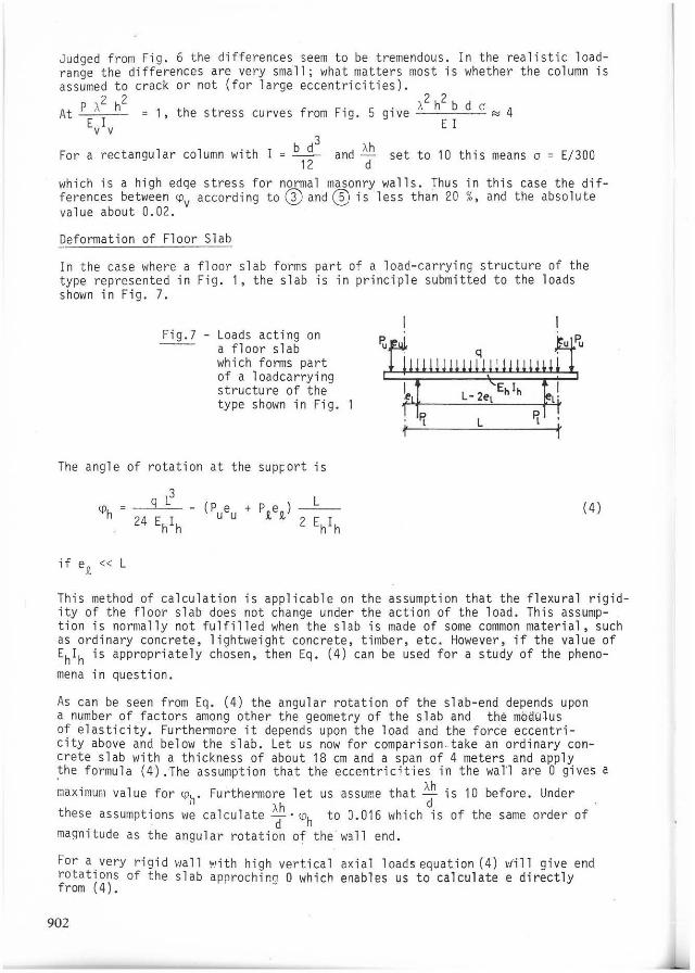
In the case where a floor slab forms part of a load-carrying structure of the type represented in Fig. 1, the slab is in principle submitted to the loads shown in Fig. 7.
Loads acting on a floor slab which forms part of a loadcarrying structure of the type shown in Fig.
The angle of rotation at the SUPéort is
if ep" « L
- (P e u u (4)
This method of calculation is applicable on the assumption that the flexural rigidity of the floor slab does not change under the action of the load. This assumption is normally not fulfilled when the slab ;s made of some common material, such as ordinary concrete, lightweight concrete, timber, etc. However, if the value of Eh1h is appropriately chosen, then Eg. (4) can be used for a study of the pheno-mena in questiono
As can be seen from Eg. (4) the angular rotation of the slab-end depends upon a number of factors among other the geometry of the slab and thé mbdulus of elasticity. Furthermore it depends upon the load and the force eccentricity above and below the slab. Let us now for comparison .. take an ordinary concrete slab with a thickness of about 18 cm and a span of 4 meters and apply the formula (4) .The assumption that the eccentricities in the wan are O gives a
~ax;murõ1 value for l:?h' Furthermore let us assume that ~h is 10 before. Under
these assumptions >le calculate Àdh . <ilh to 0.01 6 which is of the same order of maqnitude as the angular rotation of the · wall end.
Fo r a very rigid ,·,a11 ,.,ith high vertical axial 10ads eguation (4) ,ofill give end rotations of the slab approching O which enables us to calculate e directly from (4).
902
lhe calculation af the slab end rotations wil1 not be carried further since this ; s a rather simple problem. Instead we turn our interest to the deformation and strength of the joint between the slab and the wall.
Deformation and Strength of Joints
[9] EMPERGER has investigated concrete beams, and [3] KAZINCZY has examined steel beams, which were built in at the supports in brick masonry walls. These by now old investigations corroborate the assumption that the behaviour af the joint between a concrete slab and a brick masonry wal1 sha ll in some measure be plastic. The details of this behaviour rnust be determined by tests.
The difference in the angle of rotation between the slab and the wall is influenced not only by the effect of splitting, but also by the plastification of the morta r, t he bricks, and the slab at the joint between the slab and the wall. This effect af plastification can scarcely be calculated, and must therefore be determined by means af tests. lhe ma ;n difficulty met with in this connection ;5 to separate the effects of plastification and splitt ing. Consequently, it seeMs justifiable to take aCCQunt af the above-I'lentioned h/o effects at the sal'le time. and to invest igate experi~entally the total difference in the angle of totation between t l,e "alI and the.floor slab. Tois t ota l difference is denoted by o.
The only possibility to investigate the values of e is to perform full scale tests. Such tests have been reported by [10,6] SAHLIN and by [11] GERMANINO and MACCHI, [12] HENDRY and others. Since this discussion only is on a qualitative basis we here constrain ourselves to briefly recure the 1959 tests.
In the theoretical studies, we assume the following expressions for the angle of rotati on 8 of the joint:
e O for O ~ M < Mpl O < 8 ~ 8ult for M = M
pl
(5)
The ultimate value of the angle of rotation, 8 lt' is supposed to be dependent on the normal force transmitted in the joint. U
Experimental evidence
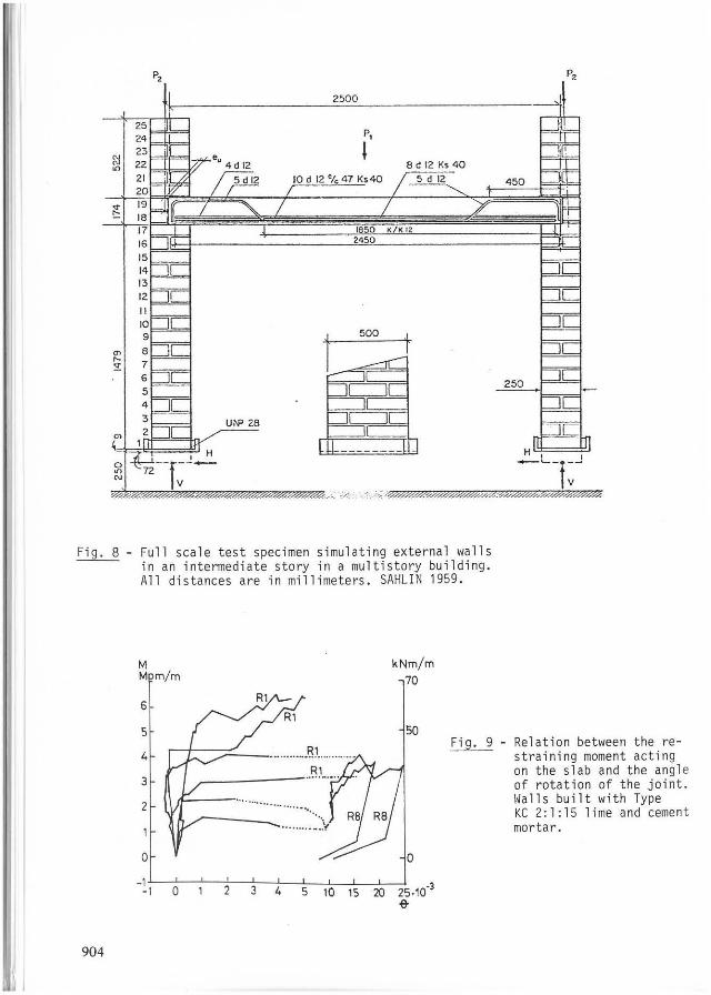
Fu ll scale tests, [6, 10] SAHLIN show that a considerably plasticity in the joints occur above a certain moment o In Fig. 8 the test set-up (1959) is exem~lified and in Fig. 9, some typical test results are shown.
903
"
I
P,
l 8 d 12 Ks 40
500
~
Jc=:::J[
U~ 28 Jc=:::J[
r - - .- !l
Fig. 8 - Full scale test specimen simulating externaI walls in an intermediate story in a multistory building. AlI distances are in millimeters. SAHLIN 1959.
M kNm/m M mim 70
6
5 50
........... .81 .... Fi g. 9
4
3
2 .........
......... ~\,
O O
- 1 -1 O 2 3 4 5 10 15 20 25.10.3
e-
904
P,
Relation between the re-stra;ning moment acting on the slab and the angl e of rotation of the joint . Wall s bui lt with Type KC 2: 1 : 15 lime and cement mortar.
Fu rthermore the tests showed that the ultimate rotation in the joints decreased with increased axial load. P. For a certain type of test the following relation was obtained
whe re
and
80 ~ 0. 03 , K = P/Pult '
Pult failure load for concentric loading
0,05
o ,
Eq
'V + ., '-.
O.'
(6)
<
't-." ., 1.0
Fig. 10 - Observed values of the angle of rotation of the jOint at the joint at the ultimate load.
(6)
(13J SINHA and HENDRY report tests on frames and found good agreements between theory and testo that gave no yielding in the joints in some cases. Similar results are reported by (11] GERMANINO and fIACCHI. Further references may be found in the books of (10J SAHLIN anó (12J HENDRY.
From fig 10 it can be observed that for low axial loads the value of the rotation in the joint is of the same arder of magnitude as the maximum rotation in the wa ll and also of the slab end. For extremely low ax ial loads i t is even twice as high as for a normal wall end rotation at failure.
It is therefore obvious that for the calculation of t he eccentricity in the wall at high loads the rotation in the joint wi11 play a very important ro11. Sometimes the joint may not yield at a11 and in such circumstances the rotation is O and the calculation is simp1ified, The writer wants to stress the need for more experimental data to faciliate the calculation of load eccentricities in masonry "a11s. Many different types of joints are used and far from a11 types have been experimentally investigated. Also all wall testing should produce data for the ang le of rotation of the >la11 end rather then the deflettion. The deflection curves can easily be fitted whether they are sinusoidal, parabloic or of almost any shape. Since the angle of rotation at the end is the derivative of the deflec tion it is much more sensitive to the choice of the formula for the def1ection curve. The def1ection curve shou1d therefore be tested for fit to the expe rimental angle of rotation rather than to the midheight deflection for a co lumn.
Unintended eccentricities
In the foregoing we have assumed that a11 structural members are perfect in mate ri al and geometri. The conditions in practice are obviously not so. Therefore one has to take a number af imperfections into account. For the determinatian af the force eccentricity in the wal1s two different kinds af unintended eccentr;cities mus t be accounted for: member imperfections and system imperfections.
905
I
~~~~~r_i~~~rf~ç~i9Q~
The imperfections of a wal1 stem from two different sources.
The first one is related to the 9~2~~trl of a wall. Inadvertently the wall is built in a bow, C-shaped, so that it deviates from a straight line from the bottom to the topo
The second type of imperfection is connected with the imperfections af the material. Even if the wall were built to a perfect geometri, upon testing it would stãri-iõ-bent in one or another direction due to the uneven distribution of the modu1us of elasticity ave r the cross section. Also some bricks and some portions of the mortar may have lower strenght and stiffness than the rest and therefore the testing machine sees the wall as if it were imperfect ar bento
The both imperfections mentioned interact together. and in practice one often co1-lects both these in one single term for practical reasons. Very often these two imperfections are combined into one. which ;s assumed to have its maximum at m;dheight of the wall, when buckling curves are established for masonry walls. Often the figure h/300 is assumed.
~t~t~~_1~~~rf~,t12~~
In practice one wall is built and then a slab is placed on top of it and thereafter the next wall is beeing built on top of the joint between the slab and the wall. It often happens that one wall is misplaced in relation to the other. This ~1~el~~~~~~t_9f_w~11~ results in 10ad eccentr;cities in the wall. These eccentricltles can De taken into account either as a misp1acement of the actual force ar by an extra moment at the joint.
It is impossible to build a wall to exact plumb and therefore the wall has a lean inwards ar outwards. This inclination must be taken into account S1nce it creates a horizontal force that has-iõ-be-iãken up via the slabs and the shear walls perpendicular to the inclined wall.
Design procedures for masonry walls
lt is obvious that an exact calcu1ation of the eccentricity as a function of the applied load as shown in beforegoing would be too complicated in many cases. In the daily design work it is therefore advis ible to use some simplifying assumptions and other design aids. For example, in the recently published [14] International Recammendations for Masanry Structures (DlB-report publication 58) it is recommended that one of three different schemes is assumed for the calculation of t he force eccentricity in a wa11).
1. The general apprach. as described. with sem;rigid joints ;n which ratations are possible in the joi nt at a reasonable constant value of the end moment af the slab and wall can sometimes be modified. This scheme is only valid within the rotation capacity of the joint and this must be checked for the limit state under examination.
2. It is also possible to use a rigid joint scheme. The plastification which takes place in the joint ;5 neg lected which of course increases the load force eccentricities.
3. A further simplification ;5 to assume hinged joints. In this scheme the eccentr;cities are assumed.
906
References
(1]
( 2]
( 3]
(4 ]
( 5]
( 6]
(B]
H. NYLANOER:
K. ANGERVO:
G. v. KAZINCZY:
K. ANGERVO A. I. PUTKONEN :
J . C. CHAPMAN J. SLATFORO:
S. SAHLIN:
R. FRISCH-FAY:
H. PARLANO:
Undersokning av barkraften hos murade cementstensvaggar (Investigation of Load-Carrying Capacity of Cement Block Masonry Walls). Betonq, Hafte 3, Stockholm 1944.
über die Knickung und Tragfahigkeit eines exzentrisch gedrUckten Pfeilers ohne Zugfestigkeit. (On the Buckling and the Bearing Capacity of an Eccentrically Compressed Pillar without Tensile Strength . ) Staatliche Technische Forschungsanstalt, Finnland, Publikation 26, Helsinki 1954 .
Oie Bemessung unvollkommen eingespannter Stahl "I"-Oeckentrager unter BerUsichtigung der plastischen Formanderungen. (The Oesign of not Fully Restrained Steel "I" -F loorbeams Considering Plastic Oeformations.) IABSE, Second Vo lume of the Publications, ZUrich 1933 - 1934.
Erweiterung der Theorie der Biegung eines Pfeilers ohne Zug festigkeit und ihre Anwendung zur Berechnung von Rahmentragwerken mit unbewehrten Stielen. (Extension of the Theory of Pillar without Tensile Strength and its Application to the Calculation of Frame Structures.) Staatliche Technische Forschungsanstalt, Finnland, Pub likat ion 34, He lsinki 1957.
The Elastic Buckling of Brittle Columns. Paper No . 6147, Proc. Instn. Civ. Engrs, vo1. 6, pp 107 - 125, January 1957
Structura l Interaction of Walls and Floor Slabs. Effect of Oeformation of Joints on Load -Carrying Capacity of Brick Masonry Walls, Light-Weight Ce llular Concrete Element Walls, and Over-Reinforced Concrete Frames. Bu llentin nr 33 of the division of Bui lding Statics and Structural Eng ineering at the Royal Institute of Technology Stockholm, Sweden. 1959.
The Internationa l Journal of Masonry Construction Volume 1 No. 2 - 1980 . Influence of tensile additives to ~ability Df masonry structures.
The State Institute for Technical Research, Finland, Publication No, 115, Helsinki 1967, The effect of Cracks and of Masonry Block Height on the Buckling Strength of a Column.
(9] F.E. v Ef1PERGER: Versuche mit eingespannten Balken. Mitteilungen Uber Versuche. Elsenbeton-Ausschuss des Osterreichischen Ingenieur- und Architekten-Verei ns, Oeuticke, Leipzig und Wien 1913.
(10] S. SAHLlN:
(11] G. GERt4AtHNO G. MACCHI :
(12] A. N. HENORY:
(13] B.P. SINHA A.W. HENORY:
( 14]
Structural Masonry (Prentice-Hall, Englewood Cliffs, N.J., 1971) pp. 91 -116.
Experimental Research of a Frame Idealisation for a Bea ring Wall Multi-storey Structure. Proc. Br . Ceram. Soc.
Structural Brickwork. The Macmi llan Press Ltd, London 19B1.
An Investigation into the Behaviour of a. Br1ck Cross Wall Structure. Proc. Br. ceram. Soc., 27(1978)67-76
CIB, International Recommendations for Masonry Structures. Pub1. 58, 19BO. CIB .