1 NASA TN D-3956 C. 1 NASA TECHNICAL NOTE FORCED-CONVECTION HEAT-TRANSFER CORRELATIONS FOR GASES FLOWING THROUGH WIRE MATRICES A SURFACE TEMPERATURES TO by Willium E. Muug and William F. Muttson Lewis Reseurch Center CleveZund, Ohio NATIONAL AERONAUTICS AND SPACE ADMINISTRATION WASHINGTON, D. C. MAY 1967 I https://ntrs.nasa.gov/search.jsp?R=19670015144 2018-05-18T18:48:01+00:00Z
Transcript
1 NASA TN D-3956 C. 1
N A S A TECHNICAL NOTE
FORCED-CONVECTION HEAT-TRANSFER CORRELATIONS FOR GASES FLOWING THROUGH WIRE MATRICES A SURFACE TEMPERATURES TO
by Willium E. Muug and William F. Muttson
Lewis Reseurch Center CleveZund, Ohio
N A T I O N A L A E R O N A U T I C S A N D SPACE A D M I N I S T R A T I O N W A S H I N G T O N , D . C. MAY 1967 I
For sole by the Clearinghouse for Federal Scientific and Technical Information Springfield, Virginia 22151 - CFSTI price $3.00
FO RC E D- CO NV ECTlO N H EAT-TR A N S FER CO R R EL AT10 N S FO R GAS E S FLO WING
THROUGH WIRE MATRICES AT SURFACE TEMPERATURES TO 5500' R
by Wil l iam L. Maag and Wi l l iam F. Mat tson
Lewis Research Center
SUMMARY
Experimental forced-convection heat-transfer data a r e presented for hydrogen, he- lium, and nitrogen gases flowing through electrically heated matrices made of helical coils of tungsten wire. eter, 0.030 to 0.050 inch; surface temperature, 1500' to 5500' R; outlet gas tempera- ture, 650' to 3000' R; mass velocity, 0.34 to 7 .01 pounds per second per square foot; heat f lux, 0.32 to 8.43 Btu per second per square inch; pressure, 1 atmosphere; poros- ity, 60 to 80 percent. The data are correlated by using the wire diameter as the charac- ter is t ic dimension, basing the Reynolds number on the minimum mass velocity, and evaluating the physical properties of the gases at both the film and bulk temperatures. These data and those of other investigators can be represented by the single-cylinder heat-transfer correlation based on the film temperature o r by a bulk-temperature corre- lation presented herein. Matrix types include coils, cylinder banks, and woven wire screens having porosities greater than 60 percent.
The following are the test conditions for these data: wire diam-
INTRODUCTION
The Lewis Research Center is investigating the use of nuclear fuel elements in space power and propulsion systems. these elements at simulated operating conditions is being done out-of-pile. these tes t s require a stea.dy-state source of hot flowing gas at temperatures up to 5000' R. The development of electrical-resistance heaters for hot-flow testing resulted in an investigation of the heat-transfer characteristics of tungsten-wire-matrix heating elements. Tungsten wire can be electrically heated to surface temperatures above 5000' R, and, as a matrix, it has a high surface-to-volume ratio and is adaptable to either high-voltage o r high-current power supplies.
For reasons of safety and economy the initial testing of Many of
There is no universal forced-convection heat-transfer correlation that encompasses the wide range of heat-transfer surface geometries that can be formed from wire. The available data listed in the l i terature indicate that each type of wire matrix exhibits slightly different heat-transfer characteristics. Reference 1 summarizes experimental data obtained for air flowing through woven matrices of different wire diameters and po- rosit ies at temperatures slightly above ambient. Reference 2 provides some variable- property data for the steady-state flow of air through electrically heated banks of cyl- inders at surface temperatures up to l l O O o R. Reference 3 presents variable-property data for hydrogen and nitrogen gases flowing through interwound helical coils of tungsten wire heated electrically to surface temperatures up to 5200' R. In each of these reports a particular correlation was obtained for each type of matrix investigated.
somewhat differently. However, if this geometry difference is not great, a single corre- lation might represent all the matrices. transfer data for one geometry and relates these data and those of other investigators of similar geometries to one general correlation.
The data presented are for hydrogen, helium, and nitrogen gases flowing through a matrix formed from helical coils of tungsten wire. The arrangement of coils differed f rom that of reference 3 in that the coils were not interwound. f rom 0.030 to 0.050 inch, and the porosity varied from 60 to 80 percent. The heat flux ranged from 0 . 3 2 to 8.43 Btu per second per square inch. The experimental data a r e correlated by using the wire diameter as the characterist ic dimension, basing the Reynolds number on the minimum mass velocity, and evaluating the physical properties of the gases at both the film and bulk temperatures. correlated herein on these same bases.
The lack of geometrical similarity is the primary reason why each matrix behaves
This report presents variable-property heat-
The wire diameter varied
The data of references 1 to 3 are
APPARATUS AND PROCEDURE
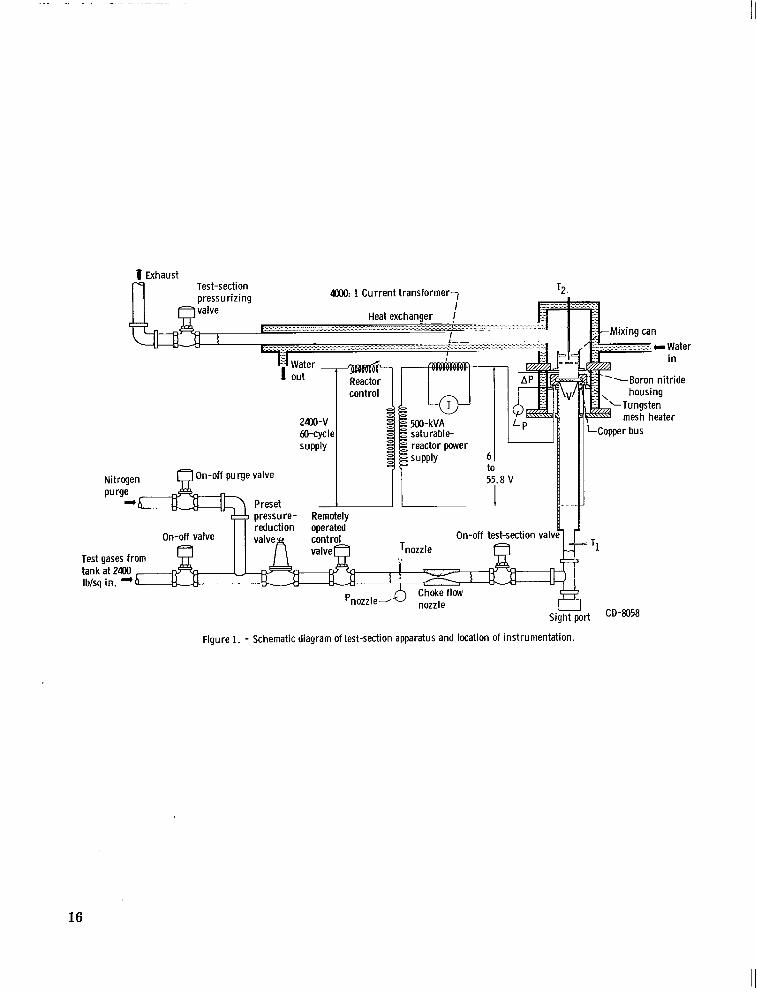
A schematic diagram of the flow system, test section, power supply, and instru- mentation and of corresponding components associated with each as used in the investi- gation is shown in figure 1.
Flow System
As may be seen in figure 1, hydrogen, nitrogen, o r helium was supplied to the flow system from a tube t ra i le r at a maximum pressure of 2400 pounds per square inch. From the t ra i ler the gas flowed through a preset pressure-reducer valve, a remotely operated control valve, a convergent-divergent flow nozzle, and an on-off valve before it entered the test section. The gas flow was metered by means of the flow nozzle, which
2
was maintained choked to ensure a constant mass flow through the tes t section. From the test section the heated gas flowed through a two-baffle molybdenum mixing can and into a gas-to-water concentric-tube heat exchanger, where it was cooled below 1000° R before it was exhausted into the atmosphere.
flow was started, and the controls were set for fail-safe operation; if a predetermined safety permissive stopped the hydrogen flow, nitrogen would automatically purge the system. In such a case, the electrical test power would also be automatically shut down.
For safety purposes, the entire system was purged with nitrogen before hydrogen
Test Section
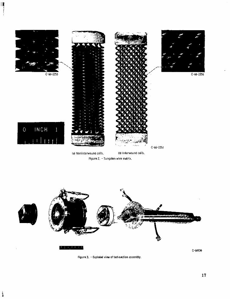
Operating experience with heating elements made from the interwound coils of refer- ence 3 showed that this type of matrix, when heated electrically, was susceptible to hot spotting and subsequent burnout at high heat fluxes. Tests showed that nonuniformities in the interwound geometry resulted in flow maldistribution within the matrix. A search fo r a similar but less flow-restrictive heating element led to a matrix made of noninter- wound coils. In figure 2 this noninterwound matrix is compared to the interwound matrix of reference 3.
Heat-transfer experiments were performed on this type of matrix formed by helical coils of tungsten wire positioned side by side with minimum spacing between coils. The various parameters are listed in table I. Both single and double rows of coils in the di- rection of flow were tested. The coils ended in a straight portion of wire which was sandwiched between two 0.060-inch-thick tungsten plates to form buses. The coil ends were heliarc welded to the plates to provide positive mechanical and electrical connec- tions. A 1/8-inch segment of the straight wire remained exposed on each end of the coil between the tungsten plates and the beginning of the helix.
Figure 3 shows an exploded view of the test section assembly. The entering flow was straightened by a 3-fOOt entrance-transition section. The gas then passed through the matrix, which was held in place by a boron nitride housing. The housing also served to insulate the bus connections of the matrix. A rubber O-ring near the cold end of the boron nitride eliminated bypassing of the gas. The gas was mixed by a molybdenum baf- fle before its temperature was measured. The outer stainless-steel support housing was water cooled.
3
I I I I I I I I1 11111111111 m1.111 1111111.1. -- -. . .-_.. --- I
Power Supply
A single-phase 60- cycle 500-kilovolt-ampere saturable-reactor-controlled power supply was used to heat the tungsten matrix electrically. Output voltage was varied from 6.0 to 55.8 volts with a maximum current rating of 10 000 amperes. With bus losses, however, the maximum power to the test element was limited to 225 kilowatts.
Instrumentation
The location of the instrumentation is shown in figure 1. The voltage across and the current through the test section were measured. The test-section voltage was taken di- rectly across the matrix to eliminate any e r r o r caused by a voltage drop between the power supply and the test section. A true root-mean-square voltmeter was used to measure the test voltage because of the nonsinusoidal waveform produced by the saturable-reactor-controlled power supply. Current was read on a precision alternating- current ammeter through a 4000: 1 step-down current transformer. Inlet temperature was measured with a type-K thermocouple (ref. 4), and the exit temperature was meas- ured with a platinum - platinum- 13-percent-rhodium thermocouple. The exit thermo- couple was placed in a baffled molybdenum mixing can to give a true mixed bulk-gas tem- perature. nozzle were made to calculate mass-flow rate. The mass-flow rate was set by adjusting the nozzle-inlet pressure.
Temperature and pressure measurements at the inlet to the choked flow
METHOD OF CALCULATION
Geometrical Factors
The matrix was made of helical tungsten coils positioned side by side. This matrix can be specified by the following parameters: (1) wire diameter d, (2) mandrel diameter (inside coil diameter) D, (3) number of parallel coils per unit width N, (4) length of coil b, and (5) helical coil pitch p.
The geometrical parameters and corresponding equations associated with the calcu- lation of the heat-transfer coefficient and of the surface temperature for the data of this report are as follows: The length S of wire in a single helical coil, including the total exposed straight segments (0.021 ft) on the coil ends, is given by the equation
4
a S = 12 d r 2 ( D + d) 2 2 + p + 0.021
and the total heat-transfer area for N number of coils is
A, = TdSN (2)
(Symbols are defined in the appendix.)
in the correlating equations of this report, gives the minimum mass velocity at a point just upstream of the matrix. It uses the total frontal area of the matrix for the cross- sectional flow area:
The mass velocity was defined in two ways. The first, which is the definition used
The second definition is that of the average mass velocity through a porous structure and is based on the average porosity of the matrix:
W Gav = - Aftc
The porosity of a homogeneous matrix is usually defined as the ratio of void volume to total volume. However, for a matrix made from noninterwound coils this definition is not realistic because of the large void volume within the center of each coil. The poros- ity of this system was therefore based on the coil volume minus the center or mandrel volume. Equation (4) defines this porosity in t e rms of one coil which is applicable to the total matrix when the coils are positioned close together:
( 4) (volume of coil -~ - ~~ volume of mandrel) - (volume of tungsten in coil)
volume of coil - volume of mandrel E =
This porosity, when multiplied by the frontal area of the matrix, approximates the aver- age flow area between turns in the coils.
5
Average Heat-Transfer Coefficients
The average heat-transfer coefficient was computed from the experimental data by the relation
where
T1 + T2 Tb = 2
The average surface temperature Ts of the matrix was determined from the re- lation between temperature and resistivity of tungsten as given in reference 5. The re- sistivity was calculated from
v Ae 5 =- - I S
where
2 A, = - lrNd
4
Average surface temperatures from the resistivity-temperature relation calculated by equation (7) were verified by means of an optical pyrometer that was sighted through a port located in the inlet-transition section of the test-section housing.
bY
The film temperature used to evaluate the physical properties of the gases is defined
Tf = Tb + Ts 2
(9)
The physical properties for hydrogen were taken from reference 6 and those for helium and nitrogen from reference 7.
6
RESULTS AND DISCUSSION
A fluid flowing normal to a single cylinder is analogous to a fluid flowing normal to a wire matrix such as those shown in figure 2. In each case a laminar boundary layer forms on the upstream portion of the surface, and flow separation generally occurs at some point on the downstream portion of the surface. A similar analogy can be made for the transfer of heat from both a cylinder and a matrix to a flowing fluid. On the front portion of the surface the heat is t ransferred through the laminar boundary layer that has developed. On the back portion the heat is transferred by the turbulent action of the wake that forms with flow separation. faces cannot be analytically defined at the present time. The factors that determine the heat-transfer coefficient for fluids flowing normal to cylinders are the same factors that define any forced-convection heat transfer; these are the mass velocity of the fluid, the physical properties of the fluid at some reference temperature, and the characteristic dimension of the system, which in this case is the cylinder diameter. For a single cyl- inder the mass velocity is based on the total cross-sectional a r ea of the flow passage. As more cylinders a r e added, a matrix is approximated, and the mass velocity of the fluid through the matrix increases as the porosity of the system decreases. However, the average porosity does not necessarily define the effective mass velocity because it does not describe the variable cross-sectional a reas available for flow. Other factors, such as the action of the turbulent wake from one cylinder on an adjacent or on a down- s t ream cylinder, will a lso affect the mass velocity. This complex fluid flow through a matrix requires that experimental data be used to define such a system empirically. The definition of mass velocity used will be that which yields the best correlation. For this investigation the minimum mass velocity based on the frontal a r ea of the matrix gave the best results.
transfer coefficient of air flowing normal to a single cylinder:
The mechanism of heat transfer from such sur -
Reference 8 recommends the following empirical equation for determining the heat-
0. 52 Nu, = 0.32 + 0.43 Re, 1 1
This equation applies for the following ranges of variables:
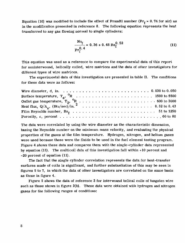
Equation (10) was modified to include the effect of Prandtl number (Prf = 0.74 for air) as in the modification presented in reference 8. The following equation represents the heat transferred to any gas flowing normal to single cylinders:
0. 52 -- - 0.36 + 0.48 Ref NUf
This equation was used as a reference to compare the experimental data of this report f o r noninterwound, helically coiled, wire matrices and the data of other investigators for different types of wire matrices.
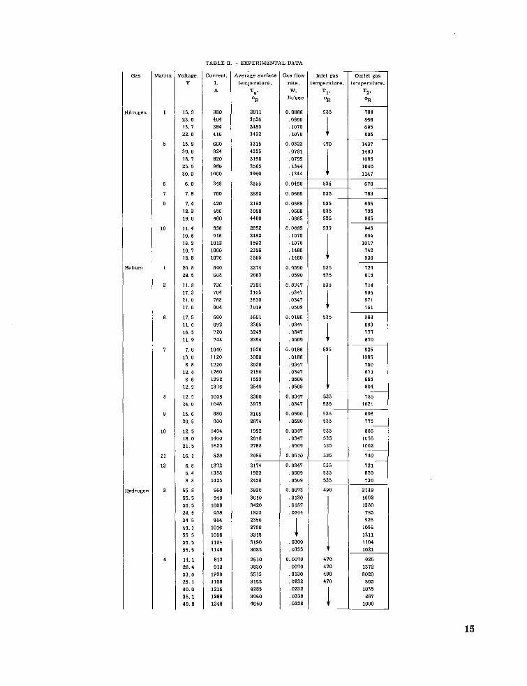
The experimental data of this investigation are presented in table 11. The conditions for these data were as follows:
The data were correlated by using the wire diameter as the characterist ic dimension, basing the Reynolds number on the minimum mass velocity, and evaluating the physical properties of the gases at the film temperature. Hydrogen, nitrogen, and helium gases were used because these were the fluids to be used in the fuel element testing program. Figure 4 shows these data and compares them with the single-cylinder data represented by equation (11). -20 percent of equation (11).
The fact that the single cylinder correlation represents the data for heat-transfer surfaces made of coils is significant, and further substantiation of this may be seen in figures 5 to 7, in which the data of other investigators are correlated on the same basis as those in figure 4.
Figure 5 shows the data of reference 3 for interwound helical coils of tungsten wire such as those shown in figure 2(b). These data were obtained with hydrogen and nitrogen gases for the following ranges of conditions:
The multicoil data of this investigation fall within +10 percent and
The majority of the data parallel the single-cylinder correlation but fall about 25 percent above it. The greater heat t ransfer for the same mass flow may be explained by the ef- fect of air flow through more than one row of cylinders. Multiple rows of cylinders in- crease the turbulence of the fluid (ref. 8) and cause greater heat transfer than that ob- tained for fluids passing over a single cylinder or over one or two rows of coils.
for the following ranges of conditions: Figure 7 shows the data of reference 1 for air flowing through woven-wire matrices
These data also f a l l above the single-cylinder correlating line. Since these test elements consisted of from 3 to 65 rows stacked together, the increased turbulence caused by the multiple rows again indicates the reason for the greater heat transfer. These data are based on bulk-temperature physical properties, whereas the data of previous investiga- t o r s were based on film temperature. This change should not be significant because the actual difference between the surface and bulk temperatures for these data was reported to be only about 30' R (refs. 1 and 9).
The data of this investigation and those of references 1 to 3 were also correlated by using the bulk temperature instead of the film temperature to evaluate the physical prop- erties of the fluids. The resul ts shown in figure 8 indicate a reasonably good correlation.
9
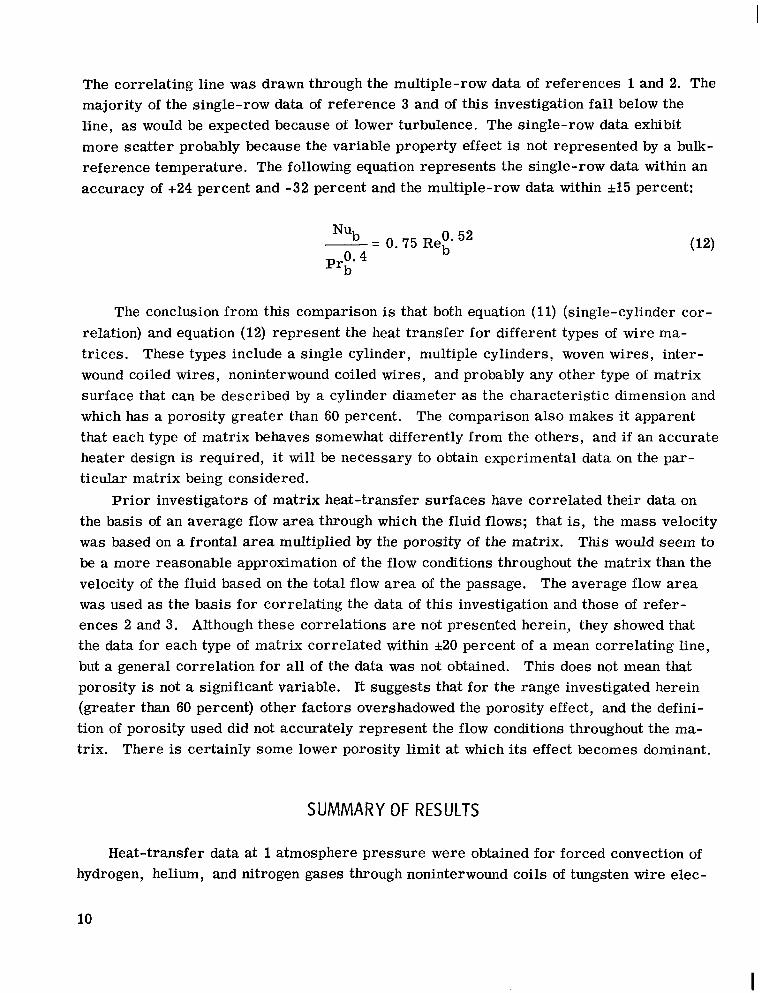
The correlating line was drawn through the multiple-row data of references 1 and 2. The majority of the single-row data of reference 3 and of this investigation fall below the line, as would be expected because of lower turbulence. The single-row data exhibit more scat ter probably because the variable property effect is not represented by a bulk- reference temperature. The following equation represents the single-row data within an accuracy of +24 percent and -32 percent and the multiple-row data within *15 percent:
The conclusion from this comparison is that both equation (11) (single-cylinder cor- relation) and equation (12) represent the heat transfer for different types of wire ma- tr ices. These types include a single cylinder, multiple cylinders, woven wires, inter- wound coiled wires, noninterwound coiled wires, and probably any other type of matrix surface that can be described by a cylinder diameter as the characteristic dimension and which has a porosity greater than 60 percent. The comparison also makes it apparent that each type of matrix behaves somewhat differently from the others, and i f an accurate heater design is required, it will be necessary to obtain experimental data on the par- ticular matrix being considered.
P r io r investigators of matrix heat-transfer surfaces have correlated their data on the basis of an average flow area through which the fluid flows; that is, the mass velocity was based on a frontal area multiplied by the porosity of the matrix. This would seem to be a more reasonable approximation of the flow conditions throughout the matrix than the velocity of the fluid based on the total flow area of the passage. The average flow a rea was used as the basis for correlating the data of this investigation and those of refer- ences 2 and 3. Although these correlations are not presented herein, they showed that the data for each type of matrix correlated within *20 percent of a mean correlating line, but a general correlation for all of the data was not obtained. This does not mean that porosity is not a significant variable. It suggests that for the range investigated herein (greater than 60 percent) other factors overshadowed the porosity effect, and the defini- tion of porosity used did not accurately represent the flow conditions throughout the ma- trix. There is certainly some lower porosity limit at which its effect becomes dominant.
SUMMARY OF RESULTS
Heat-transfer data at 1 atmosphere pressure were obtained for forced convection of hydrogen, helium, and nitrogen gases through noninterwound coils of tungsten wire elec-
10
I
trically heated to surface temperatures up to 5500' R. Outlet gas temperatures as high as 3000' R were obtained, and film Reynolds numbers based on wire diameter and total- passage flow area varied from 50 to 1250. The results of comparing these data and those of other investigators are as follows:
inders, interwoven wires, interwound coils, and noninterwound coils can be represented by the single-cylinder heat-transfer correlation o r by the correlation presented herein.
2. The different geometries of the various types of matrices cause each to possess slightly different heat-transfer characteristics. If a high degree of accuracy is required for the design of a matrix heat-transfer system, it will be necessary to obtain experi- mental data on the particular matrix being considered.
1. The experimental data for mesh heat-transfer surfaces made from single cyl-
Lewis Research Center, National Aeronautics and Space Administration,
Cleveland, Ohio, January 26, 1967, 120-27-04-56-22.
11
APPENDIX - SYMBOLS
Ae
Aft
AS
b
C P
D
d
Gav
Gmin
h
I
k
M
N
Nu
P
Pr
A P
current - f lo w cross -sectional area, s q f t
frontal area, s q f t
heat-transfer surface area, sq f t
length of coil, f t
specific heat of gas at constant pres sure, Btu/( 1 b) (OR)
mandrel diameter, f t
wire, or cylinder, diameter, f t
average mass velocity within ma- trix, (Ib/sec)/sq f t
mass velocity upstream of matrix, (Ib/sec)/sq f t
Btu/( s e c) (sq f t ) (OR) average heat - transf er coefficient,
current, A
thermal conductivity of gas, Btu/(ft) (sec) (OR)
number of coil rows
number of parallel coils per unit width
Nusselt number, hd/k
pressure, psig
Prandtl number, c p/k
differential pressure, psi P
P
Q
Re
S
T
Tb
TS
T1
T2 V
W
E
P
5
coil pitch, ft/turn
rate of heat transfer to gas, Btu/sec
Reynolds number, dG/p
total wire length of helical coil,
temperature, OR
average bulk temperature,
f t
(TI + q / 2 , OR
average surface temperature,
inlet gas temperature, OR
outlet gas temperature, OR
voltage, V
gas flow rate, Ib/sec
matrix porosity, percent
absolute viscosity of gas,
OR
lb/(sec) (ft)
resistivity of tungsten, ohm-ft
Subscripts :
b bulk
f film
S surface
12
REFERENCES
1. Kays, W. M. ; and London, A. L. : Compact Heat Exchangers. The National Press (Palo Alto, Calif.), 1955.
2. Gedeon, Louis; and Grele, Milton D. : Forced-Convection Heat-Transfer and Pressure-Drop Characteristics of a Closely Spaced Wire Matrix. NACA RM E54D12, 1954.
3. Siegel, Byron L. ; Maag, William L. ; Slaby, Jack G. ; and Mattson, William F. : Heat-Transfer and P res su re Drop Correlations for Hydrogen and Nitrogen Flowing Through Tungsten Wire Mesh at Temperatures to 5200' R. NASA TN D-2924, 1965.
4. Anon. : Thermocouples and Thermocouple Extension Wires. Rev. Composite of RPI. 9-RPI. 7, Instr. SOC. Am. , July 1959.
5. Anon. : Temperature Its Measurement and Control in Science and Industry. Reinhold Publishing Corp., 1941, p. 1318.
6. Grier, Norman T. : Calculation of Transport Properties and Heat-Transfer Param- eters of Dissociating Hydrogen. NASA TN D-1406, 1962.
7. Hilsenrath, Joseph, et. al. : Tables of Thermal Properties of Gases. National Bu- reau of Standards Circular 564, Nov. 1, 1955.
8. McAdams, William H. : Heat Transmission. 2nd ed. , McGraw-Hill Book Co. , Inc. , 1942.
9. Coppage, S. E. : Heat Transfer and Flow Friction Characteristics of Porous Media. Tech. Rept. No. 16, Dept. of Mech. Engin., Stanford University, Dec. 1, 1952.
13
Mesh lumber
1 2 3 4 5 6 7 8 9
10 11 12
TABLE I. - MATRIX GEOMETRIC PARAMETERS
[Matrix s ize and channel flow area , 3 in. long by 1 in. wide. ]
Wire iiameter,
d, in.
0.030
.050
.050
.050
.050
.050
Mandrel diameter,
D, in.
0.060 .060 . l o o .060 . l o o . l o o . l o o ,060 . l o o . l o o . l o o . l o o
Parameter ~
Number of parallel coils,
N -
8 9
11 8
11 6
11 6 5 9 5 9
Number of coil rows,
M
1 1 2 1 2 1 2 1 1 2 1 2
-
Zoil pitch,
P, in. /turn
0.060 .120 .060 .080 .080 .160 .160 . l oo . l o o . l oo .200 .200
Figure 8. - Correlation of matrix heat-transfer data.
io0 1000 2000 4000
NASA-Langley, 1967 - 12 E-3651
"The aeronautical and space activities of the United States shall be conducted so as to contribute . . . to the expansion of human knowl- edge of phenomena in the atmosphere and space. The Administration shall provide for the widest practicable and appropriate dissemination of information concerning its activities and the results tbereof ,"
-NATIONAL AERONAUnCS AND SPACE ACT OF 1958
NASA SCIENTIFIC AND TECHNICAL PUBLICATIONS
TECHNICAL REPORTS: Scientific and technical information considered important, complete, and a lasting contribution to existing knowIe&e.
TECHNICAL NOTES: Information less broad in scope but nevertheless of importance as a contribution to existing knowledge.
TECHNICAL MEMORANDUMS: Information receiving limited distribu- tion because of preliminary data, security classification, or other reasons.
CONTRACTOR REPORTS: Scientific and technical information generated under a NASA contract or grant and considered an important contribution to existing knowledge.
TECHNICAL TRANSLATIONS: Information published in a foreign language considered to merit NASA distribution in English.
SPECIAL PUBLICATIONS: Information derived from or of value to NASA activities. Publications include conference proceedings, monographs, data compilations, handbooks, sourcebooks, and special bibliographies.
TECHNOLOGY UTILIZATION PUBLICATIONS: Information on tech- nology used by NASA that may be of particular interest in commercial and other non-aerospace applications. Publications indude Tech Briefs, Technology Utilization Reports and Notes, and Technology Surveys.
Details on the availability of these publications may be obtained from: