1 Forced Convection Heat Transfer Enhancement Using a Self-oscillating Impinging Planar Jet Cengiz Camci 1 & Frank Herr 2 Turbomachinery Heat Transfer Laboratory The Pennsylvania State University, Department of Aerospace Engineering 223 Hammond Building, University Park, PA, 16802 Impinging jets are widely used in the local enhancement of heat removed from internal passages of gas turbine blades. Arrays of stationary jets are usually impinged on surfaces of internal cooling passages. The current practice is to benefit from the high heat transfer coefficients existing in the vicinity of the jet impingement region on a target wall. The present study shows that a self- oscillating impinging-jet configuration is extremely beneficial in enhancing the heat removal performance of a conventional (stationary) impinging jet. In addition to a highly elevated stagnation line Nusselt number, the area coverage of the impingement zone is significantly enhanced because of the inherent sweeping motion of the oscillating coolant jet. When an oscillating jet (Re=14,000) is impinged on a plate normal to the jet axis (x/d=24 hole to plate distance), a typical enhancement of Nu number on the stagnation line is about 70 %. The present paper explains detailed fluid dynamics structure of the self-oscillating jet by using a triple decomposition technique on a crossed hot wire signal. The current heat transfer enhancement levels achieved suggest that it may be possible to implement the present self-oscillating-impinging-jet concept in future gas turbine cooling systems, on rotating disks, glass tempering/quenching, electronic equipment cooling, aircraft de-icing, combustors and heat exchangers. 1 Professor of Aerospace Engineering, member ASME, ([email protected]) 2 Present address: Tenneco Corp., Walker Eng. Center, 3901 Willis Road, Grass Lake, Michigan, 49240
Transcript
1
Forced Convection Heat Transfer EnhancementUsing a Self-oscillating Impinging Planar Jet
Cengiz Camci 1 & Frank Herr 2
Turbomachinery Heat Transfer LaboratoryThe Pennsylvania State University, Department of Aerospace Engineering
223 Hammond Building, University Park, PA, 16802
Impinging jets are widely used in the local enhancement of heat removed from internalpassages of gas turbine blades. Arrays of stationary jets are usually impinged on surfaces of internalcooling passages. The current practice is to benefit from the high heat transfer coefficients existingin the vicinity of the jet impingement region on a target wall. The present study shows that a self-oscillating impinging-jet configuration is extremely beneficial in enhancing the heat removalperformance of a conventional (stationary) impinging jet. In addition to a highly elevated stagnationline Nusselt number, the area coverage of the impingement zone is significantly enhanced because ofthe inherent sweeping motion of the oscillating coolant jet. When an oscillating jet (Re=14,000) isimpinged on a plate normal to the jet axis (x/d=24 hole to plate distance), a typical enhancement ofNu number on the stagnation line is about 70 %. The present paper explains detailed fluid dynamicsstructure of the self-oscillating jet by using a triple decomposition technique on a crossed hot wiresignal. The current heat transfer enhancement levels achieved suggest that it may be possible toimplement the present self-oscillating-impinging-jet concept in future gas turbine cooling systems,on rotating disks, glass tempering/quenching, electronic equipment cooling, aircraft de-icing,combustors and heat exchangers.
1 Professor of Aerospace Engineering, member ASME, ([email protected])2 Present address: Tenneco Corp., Walker Eng. Center, 3901 Willis Road, Grass Lake, Michigan, 49240
2
NOMENCLATURE
d = nozzle throat width , see Figure 2 (linear dimension)f = oscillation frequency of the jeth = convective heat transfer coefficientH = thickness of the plexiglass impingement platei,j,k = summation indicesk = thermal conductivitym,n = exponents in Nu number correlationNu = Nusselt number, Nu=hd/kp = instantaneous pressureP = time averaged pressurePr = molecular Prandtl numberq = wall heat flux rateq = turbulent kinetic energy using u,v,wq* = oscillation kinetic energy using u*,v*,w*Re = Reynolds number, Re=Ud/ν, based on bulk velocity of the
jet at the throat sectiont = timeT = temperatureU,V,W = mean velocity componentsu,v,w = velocity fluctuations due to stochastic fluctuations
The advancement of high performance thermal systems has stimulated interest in methods to
improve heat transfer rates, especially on the coolant side of hot surfaces. Considerable efforts have
been made to increase heat transfer rates by implementing passive enhancement methods that
require no direct consumption of external power. The present study deals with a heat transfer
enhancement method using planar cooling jets in a self-sustained oscillatory flow mode. Utilizing an
impinging jet in oscillatory mode has great cooling potential for hot section components. This
method is based on the enhancement of turbulent mixing processes on the coolant side of hot
surfaces by generating additional turbulent mixing via periodic oscillations in the impingement
region. The term “oscillation” is used for the periodic flapping motion of the jet in a direction
normal to orifice/nozzle axis. An obvious advantage of using self-sustained oscillations is that the
4
power for oscillation is drawn from the existing flow field. The oscillations can easily be generated
by a simple orifice/nozzle configuration that has no moving components even in relatively small
coolant passages. The flapping motion of the turbulent planar jet spreads the effective thermal
transport features over a relatively large impingement area on the target plate. A typical
enhancement of Nu number near the stagnation line can be as high as 70 % over stationary jet values.
Stationary impinging jets are widely used to provide high local mass/momentum/heat transfer
in a variety of applications including gas turbine cooling, paper drying, helicopter rotor blade de-
icing system, glass manufacturing, food processing, etc. Impinging jet systems are popular because
of the relative ease of controlling the specific area needed to be cooled/heated/dried and high local
heat transfer rates on the target surface. Reviews of earlier heat transfer studies on stationary
impinging jets are given in Martin (1977) and Goldstein et al. (1986). Gardon and Cobonpue (1962)
described the rate of heat transfer to an impinging jet as proportional to the difference between the
target plate temperature and the adiabatic wall temperature, which varied from point to point on the
impingement surface. Gardon and Akfirat (1965) noted that the level of turbulence in the jet had a
significant effect on the rate of heat transfer between the target plate and the stationary jet. Heat
transfer from a flat surface to an oblique impinging jet was studied by Goldstein and Franchett
(1988) and Foss (1979). Most studies have involved jets of the same temperature as the ambient
fluid. However, when the temperature of the jet is different from that of the ambient air, entrainment
of ambient air into the jet complicates the heat transfer problem, Goldstein, Sobolik and Seol (1990)
and Goldstein and Seol (1991). Stationary impinging jet based cooling arrangements are currently
extremely popular in gas turbine cooling engineering and process engineering.
Fluidic oscillatory nozzles as simple and effective mixing devices have been used by Viets
(1975). An extension of the fluidic nozzle concept to supersonic flow conditions is described by
Bremhorst, Hailye and Rice (1990) and Raman, Hailye and Rice (1993). These are detailed fluid
mechanics studies geared towards using the unsteady motion to actively control viscous flow near
surfaces. The current study uses the fluidic oscillating nozzle as a heat transfer augmentation
method for general heat transfer applications. The self-oscillating impinging jet improves thermal
transport via periodic flapping motion of the jet. The area coverage of the impingement zone is also
greatly enlarged by the flapping motion. Details of an analytical flow model for the self-oscillating-
5
impinging jet used in this study is given by Herr and Camci (1994.a). The analytical model based on
a corrected similarity technique is validated via hot wire measurements using a crossed wire. A
decomposition approach was used to identify the contribution due to the deterministic jet
oscillations and stochastic turbulent fluctuations. The governing equations are derived for oscillating
flows with fixed flapping frequency. At a given time, the oscillatory flow field can be approximately
described by the solution of a stationary jet flow obtained from a nozzle/orifice attached to a relative
reference frame that is oscillating at a prescribed frequency. The corrected similarity solution
predicts the axial/lateral mean velocity measurements and oscillation kinetic energy data well, Herr
(1995).
Oscillation of the planar jet flow enhances transport process near the target plate because of
the existence of additional inertia forces (oscillation stress) and additional thermal fluxes (oscillation
heat flux). Experiments show that most of the kinetic energy in the oscillatory jet is contained in the
deterministic unsteady part. The magnitude of the unsteady kinetic energy convection due to the
flapping motion of the jet is about three times of that due to turbulence. The individual terms of the
kinetic energy conservation equation sampled/evaluated from the measured crossed hot wire data
show that the convection of kinetic energy in oscillatory flows is stronger than the convection due
to turbulent fluctuations. It is concluded that deterministic unsteadiness enhances transport process
significantly, Herr and Camci (1994.b). Oscillation increases convection and diffusion significantly.
Enhancement of impingement heat transfer using a self-oscillating circular nozzle is described
in Page, Chinnock and Seyed-Yagoobi (1996). This acoustic excitation technique is based on the
matching of the shear tone and organ pipe frequency of the pipe’s finite length. The flow
visualization studies revealed free transverse wave oscillations and enhanced vortex shedding. A
collar extension approach results in enhancements in surface transport phenomena. An oscillation
frequency of 5000 Hz from a self-oscillating nozzle resulted in measurable heat transfer coefficient
enhancement. The nozzle-to-plate distance varied between 4 to 6 diameters. Azevedo, Webb and
Queiroz (1994) used a mechanical rotating ball valve to generate pulsations in axial velocity of a
circular jet. The axial velocity in time varies between a peak and a minimum in each period created
by valve rotations. This approach results in degradation in heat transfer coefficients on the
impingement plate. The nozzle to plate distance varies between 2 to 10 diameters. The authors
6
claim that the type of pulsations generated in this study adds energy primarily on the large scale,
with little superimposed small scale turbulence. Liu and Sullivan (1996) studied heat transfer from
an acoustically excited circular impinging jet. The investigation is performed with a nozzle having an
exit diameter of 12.7 mm and a nozzle to plate spacing less than two diameters. A loudspeaker
attached to one side of a rectangular plenum chamber induces organ pipe resonance in the chamber
producing pane-wave excitation at the jet exit. The perturbation velocity can be adjusted between
0.05 % and 0.18 % in a frequency range from 600 to 2500 Hz. At small nozzle-to-plate spacing
(less than two diameters), the local heat transfer in the wall jet region can be significantly affected by
exciting the impinging jet. The heat transfer near the stagnation point remains unchanged. The
random vortical structures enhance the local heat transfer. The strong large-scale well-organized
vortices formed after the stable pairing induce the unsteady separation of the wall boundary layer
and hence, lead to the local heat transfer reduction. Mladin and Zumbrunnen (1997) use a rotating
ball mechanism to generate a planar air jet with pulsations. The nozzle-to-plate separation distance
varies between 0 to 10 nozzle widths with a pulse amplitude ranging from 0 to 50 % of the mean
flow velocity. Pulsation frequencies range from 0 to 80 Hz corresponding to Strouhal numbers
below 0.106 based on nozzle width and jet discharge velocity. Heat transfer enhancements up to 12
% near the nozzle mid-plane due to surface renewal effects and up to 80 % at distances downstream
due to increased turbulence levels are measured where both the pulse amplitude and Strouhal number
are the highest. Pulses of small amplitude and low frequency induces a quasi steady behavior at
small separation distances, with no significant effect on the time averaged heat transfer near the
nozzle mid plane. However, at larger separation distances, increased turbulence associated with the
decay of the flow pulse enhanced the time averaged heat transfer away from the nozzle mid plane
by up to 20 %.
All of the studies reviewed in the previous paragraph focus on the nozzle to plate distances
less than 10 jet diameters (or widths). Although Page et al.’s (1996) study uses a self sustained
oscillation mode that does not require external power to maintain pulsations, Liu and Sullivan
(1996), Mladin and Zumbrunnen (1997) and Azevedo et al. (1994) use loudspeaker and rotating ball
valve arrangements that are powered externally. The current study is different from the studies
summarized in this paragraph for two main reasons. First, the nozzle-to-impingement plate distance
7
of the current study (24<x/d<60) is geared towards engineering applications that can be found in
food processing, drying, gas turbine cooling, glass tempering and aeronautical de-icing systems. The
second main difference is in the character of unsteady jet motion imposed. The current study
benefits from a self-oscillating impinging jet configuration that improves thermal transport via
periodic flapping motion of the jet. The area coverage of the flapping fluid motion that is influencing
the impingement plate zone is much greater than the coverage of all other studies reviewed in this
section. Although the jets acoustically excited (or mechanically oscillated by a rotating ball valve)
usually develop strong longitudinal oscillations they influence a limited impingement area on the
target plate. The current self-oscillating planar jet in flapping mode has relatively larger area coverage
on the target plate.
The present study focuses on the heat transfer aspects of self-oscillating impinging jets used
in thermal system engineering. High-resolution heat transfer measurements are presented in a Re
number range between 7,500 and 14,000 (24<x/d<60). This range is sufficiently wide for many
current thermal engineering applications. It is possible to implement the present self-oscillating-
impinging-jet concept in future gas turbine cooling systems, on rotating disks, in electronic
equipment cooling, aircraft de-icing systems and heat exchanger systems.
EXPERIMENTAL SETUP AND PROCEDURES
Oscillating jet assembly: The operation principle of an oscillatory jet is based on the fact that a
jet exiting into space between two sufficiently near walls is bi-stable, i.e. may attach to either wall.
In addition, a small pressure gradient across the jet at the throat may cause the jet to detach one wall
and attach to the opposite one. A simple fluidic nozzle representation of the oscillatory jet used in
this study is shown in Figure 1. The air flows through a nozzle shaped contraction, past two
communication ports, into an expansion section. The output ports are attached to each other via a
communication loop. Due to the proximity of the wall at the nozzle throat, the jet is bi-stable and
must attach to one of the walls. Consider the jet to be attached to wall A. Due to large amount of
entrainment into the jet, the pressure at the control port A’ is relatively low while the pressure at
the port B’ is relatively high. Since the ports are attached to each other by a feedback loop, a
compression wave travels from port B’ to port A’ tending to raise the pressure there and push the
8
jet off the wall. Simultaneously, an expansion wave originates at port A’ and travels to port B’,
tending to lower the pressure there and pull the jet onto the wall B. Thus, in a well designed nozzle,
the jet will oscillate between walls A and B at a frequency determined by the length of the line
connecting ports A’ and B’ and the line diameter. The frequency is also a weak function of the
stagnation pressure entering the nozzle. The improved mixing characteristics of the oscillatory jet
are seen in the increased spread angle and in the voids of stagnant gas that are entrained between the
waves of the oscillation, Herr and Camci (1994.a, 1994.b).
The flow and heat transfer tests for the current oscillating jet concept have been performed
using precision Aluminum nozzles. The planar nozzle sections are precision-machined using fine,
spline fitted coordinate points. The nozzle pieces are enclosed in 1.25 cm thick plexiglass sidewalls
as shown in Figure 2. A regulated laboratory compressed air supply is fed into the nozzle. The jet
emerges from the nozzle having d=5 mm throat width (nozzle height is W=25 mm) at a typical mean
velocity of 25 m/s (Re=104). To study the oscillation caused by the mechanism described above, the
unsteadiness of other means must be minimum. With two communicating ports closed, the velocity
at the throat has been kept constant within 1 %. For steady flow situation, the jet is laminar, having
a turbulence intensity of approximately 0.1 % at the exit plane. The oscillation frequency of the jet
is in the range of 10-100 Hz. This frequency is controlled by the stagnation pressure, nozzle throat
width, and the length/diameter of the communicating loop. Other details of the experimental set-up
can be found in Herr (1995)
Steady/unsteady flow field measurements: Instantaneous velocity measurements have been
taken with a TSI 1249A-T1.5 miniature 900 crossed hot wire probe and a TSI 1210-T1.5 general
purpose single sensor probe using TSI series 1050 constant temperature anemometer. The single
sensor probe has been used to measure the jet exit flow at the nozzle throat plane. The crossed wire
probe has been calibrated in a velocity range from 0.5 to 40 m/s using a full velocity-yaw angle
calibration scheme (±45o). The specific calibration scheme is the one defined by Lueptow et al.
(1988) and modified by Panchepakesan and Lumley (1993). This stretching coordinate
transformation approach improves the measurement resolution al low velocities. Unsteady flow
data are sampled at a rate of 10 KHz for 5 seconds. A local averaging technique is used to detect the
9
fronts of the periodical signals and 100 periods are ensemble averaged. Details of the current crossed
hot-wire measurement method are presented in Herr (1995).
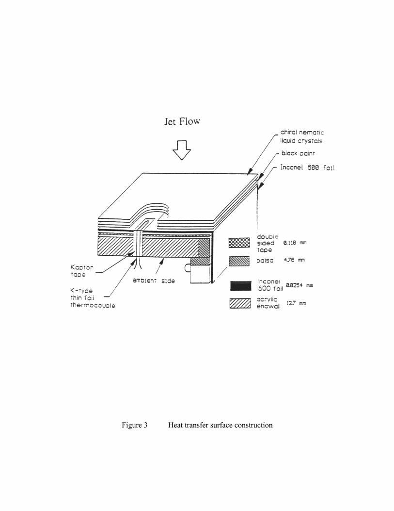
Heat transfer measurements on the target plate: The target heat transfer surface, located
downstream of the nozzle is shown in Figure 2. The target plate to nozzle distance has been varied
from 24 to 60 nozzle throat width “d” during the experiments. The impingement plate is made up of
1.25 cm thick clear acrylic. The heat transfer surface is a composite system that includes a double-
sided tape layer, Inconel heater foil, black backing paint, a liquid crystal thermo-indicator layer and
flush mounted surface thermocouples. Details of the composite heat transfer surface are shown in
Figure 3. A low resistivity rectangular steel foil (Inconel-600) has been used as a constant heat flux
surface on the target plate. The resistance of the steel foil has been accurately determined using a
Keithley 580 micro-ohmmeter to an uncertainty of ± 0.001 Ω. A DC current reversal method
removing unwanted offset voltages has been used. This technique lowers random noise in resistance
measurements. Wall temperature measurement on the heat transfer surface has been made by using
several flush-mounted thin-foil thermocouples of K type. Details of the heat transfer surface
construction are given in Wiedner and Camci (1996) and Herr (1995). Flush mounted thermocouples
have been inlaid in several spanwise locations along the impingement plate and the junctions have
been located at mid-point, Figure 3, Herr (1995). The impingement plate shown in Figure 2 has been
traversed in the y direction. The ambient side temperature of the heat transfer surface has also been
monitored continuously for conduction heat loss calculations. The losses from the impingement side
to the ambient side have been considered in the calculation of the convective heat transfer
coefficient. A variable current DC power supply has been used to heat the constant heat flux
surface. The jet and the ambient air in the laboratory are at the same temperature. The convective
heat transfer coefficient is defined as,
h = qconv/(Tw-Tchar) (1)
where qconv is convective heat flux rate, Tw the wall temperature and Tchar the characteristic
temperature. The Nusselt number for this problem is based on the nozzle throat width d,
10
Nu = hd/k . (2)
In the present study, the reference temperature Tchar is taken as the total temperature of the jet, To .
The uniform wall heat flux value over the rectangular surface was fixed at a constant level for all
tests. The heat flux generated by Joule heating of the steel foil is balanced by convective, conductive
and radiative heat flux,
qgen = qconv+qcond+qrad . (3)
The conduction heat loss from the impingement side to the back side of the plate is assumed to be
one-dimensional,
qcond = kplate ∂T/∂y = kplate (Tw-Tw,back)/H (4)
where Tw is the wall temperature on the heat flux surface, Tw,back is the temperature of the back side
of the target plate and H is the thickness of the target plate. During a typical run, conduction losses
account for approximately 6-12 % of the generated heat flux. Radiation heat transfer was estimated
using the assumptions of black body emissivity and thermal equilibrium between the jet and
sidewalls. The shape factors were approximated using an enclosure model and considering each
surface as black. The radiation heat flux is approximately 3-9 % of the local generated heat flux.
Experimental uncertainties: The final experimental uncertainty estimates of the current study are
described using the method given by Kline and McClintock (1953). The uncertainty levels presented
are analogous to 95 % coverage or 20:1 odds. A crossed hot wire sensor has been used to measure x
and y components of the instantaneous velocity field in which temperature variation in the flow
field is not significant. The Inconel strip heater used in constant heat flux measurements on the
target plate has been disconnected from the DC power supply during hot wire measurements. This
approach assures an isothermal flow field that is essential for high quality hot-wire measurements.
The instantaneous field has then been de-composed into mean, deterministic and random parts for
further analysis. The sources of error in hot wire measurement include flow field temperature
11
variations, thermal inertia of the sensors, probe misalignment, sampling time errors, constant
temperature anemometer noise. The cut-off frequency used has been selected as 4 KHz with an
overheat ratio of 1.6. It has been noted from a power spectral density calculation that, energy
content of the flow is extremely small for the frequencies higher than 600 Hz. A 0.5 o alignment
error is assumed in the uncertainty analysis. This error contributes 0.1 % to the total error. The
predicted error in instantaneous velocity measurements is about 1 %. A detailed account of the error
analysis on hot wire measurements is presented in Herr, (1995)
The heat transfer measurements on the constant heat flux surface are influenced from the
errors made in the determination of wall temperature Tw, total temperature To of the jet (ambient),
heat flux measurement, throat width measurement and absolute error in thermal conductivity k of
air. Our experiments by varying the black paint and liquid crystal layer thickness showed that the
wall temperature error δ(Tw-Tchar)/(Tw-Tchar) is less than 3.4 %. This error is already included in the
final uncertainty value of Nusselt number 6.3 % approximately. Estimates of the precision index and
bias error values for the main measured quantities in the uncertainty analysis are given in Table 1.
Further details of the uncertainty analysis are presented in Herr (1995).
Precision index Bias Error Uncertainty
qgen 1.0 % 0.3 % 1.0 %
qcond 5.5 % 5.9 % 8.1 %
qrad 1.6 % 1.9 % 2.5 %
(Tw-Tchar) 2.7 % 2.6 % 3.4 %
Table 1
Estimates of the precision index and bias error values used for the uncertainty analysis
12
EXPERIMENTAL RESULTS AND DISCUSSION
Jet half width and effective mixing: A useful indication of effective mixing in a jet is the variation
of the jet half width in axial direction. The definition of the half width at any streamwise position is
the distance between the jet centerline and the point where the local velocity is equal to half of the
centerline velocity. Current experiments clearly show that the introduction of the oscillatory motion
dramatically increases the jet half width. At x/d=60, (Re=10,000), the half width from a stationary
jet is about 8 times the nozzle throat width d. However, when the same jet is put into a self-
oscillatory motion, the half width increases to 13 times the throat width, Herr (1995). This
observation is closely related to the fact that a cooling jet in a flapping motion covers a much wider
impingement area when compared to a stationary jet. Enhanced turbulent transport with effective
mixing is spread over a much larger impingement zone on the target surface via the use of an
oscillating jet.
Frequency of self-sustained jet oscillations: The oscillation frequency of the jet is determined
by taking the fast Fourier transform of instantaneous hot wire data from the exit of the nozzle at,
η=y/x=0. Figure 4 shows the variation of oscillation frequency with respect to nozzle throat width
d for constant stagnation pressure in the plenum chamber, (φ=20o). Experiments performed at x=180
mm also show that larger throat widths at a fixed communication line length induce higher oscillation
frequencies. Similar trends have been observed at y/x=0, y/x=0.05 and y/x=0.3. Increasing d from 1
mm to 5 mm provides a five-fold frequency increase from 15 to 75 Hz. Increasing the length of the
communication line slightly reduces the oscillation frequency. For the case of increased throat width,
the amount of fluid entraining into the throat area increases. Thus the ambient air enters the feedback
tube sooner than the case which has a smaller throat width. If the width is too large, the pressure
gradient across the jet is not strong enough to move the jet and the jet would not bend to either wall,
so that no oscillation will occur. Increasing plenum chamber stagnation pressure and shorter
communication lines has a tendency to increase the frequency of oscillations, Herr (1995).
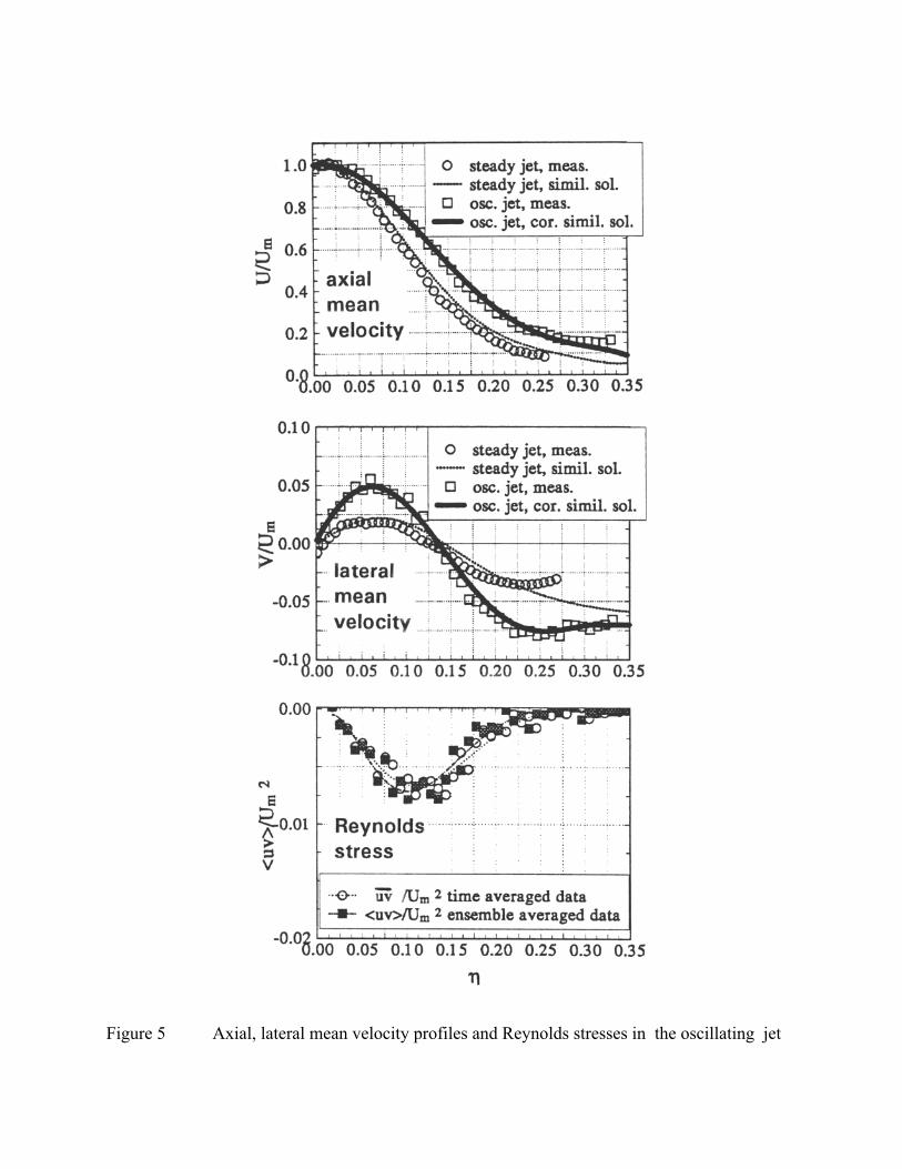
Axial and lateral mean velocity components: Mean velocity components have been measured
by time averaging the instantaneous hot wire signal at various η=y/x locations at x/d=60 for f=75
Hz. It should be noted that the data discussed from this point on include only the results for the
13
nozzle that has a throat width of d=5mm and a nozzle half angle of φ=20o. The measured axial mean
velocity (U/Um) distribution of the oscillatory jet is relatively fuller than that of the stationary jet as
shown in Figure 5. This is expected because oscillation increases the spreading rate of the jet. The
lateral mean velocity (V/Um) distribution of the oscillating jet is enhanced when 0<y/x<0.14,
(η=x/d=60). The flapping motion of the jet issued from the fluidic nozzle provides increased
transport of mean kinetic energy in the lateral direction. This feature is directly related to the
observed enhancements in jet half width leading to increased transport in the lateral direction, Herr
(1995). The thick solid lines in Figure 5 represents the predictions from "the corrected similarity
method" developed by Herr and Camci (1994.a). "The corrected similarity method" is an analytical
extension of the stationary turbulent jet solution with special emphasis paid to deterministic
oscillations of the jet. Figure 5 shows that "the corrected similarity method" based prediction of
mean velocities is in very good agreement with hot wire measurements where 0<y/x<0.275. The
stationary turbulent jet solution for U and V (based on a conventional similarity method) is
represented by tiny dots in Figure 5.
Additional stresses and heat fluxes due to deterministic oscillations: The instantaneous
velocity and temperature can be decomposed into three parts, Hussain and Reynolds (1970), a time
averaged quantity (Ui,Θ), ensemble averaged deterministic oscillations (ui*,θ*) and stochastic
turbulent fluctuations (ui,θ),
u U u uii i i
~*
~
*
= + +
= + +θ θ θΘ(5)
In an oscillatory flow, the continuity equation can be decomposed as,
∂∂
∂∂
∂∂
Ux
ux
ux
i
i
i
i
i
i
+ + =*
0 (6)
14
Finally, the time averaged momentum equation for a flow with self-sustained oscillations is as
follows,
∂∂ ρ
∂∂
∂∂
ν ∂∂
( )( )* *
U U
xPx x
Ux
u u u ui j
j i j
i
j
i j i j= − + − +1
(7)
∂ θ∂
∂∂
γ ∂θ∂
θ θ( )
( )* *U
x x xu uj
j j j
j j= − + (8)
Equation 7 clearly shows that in addition to shear stress due to molecular viscosity, there are two
additional apparent stresses termed as -ui*uj
* and -uiuj . The apparent stress terms are generated
by the non-linear inertia term (convective acceleration) that is the left hand side of the instantaneous
momentum equation. Additional inertia force due to random oscillations of the turbulent field is
usually termed as Reynolds stress -uiuj . The term -ui*uj
* is due to the inertia force originating from
deterministic variations of the oscillating jet flow. This extra stress term is named as oscillation
stress -ui*uj
* throughout this study. Similar to the developments leading to equation 7, one can
obtain a time averaged thermal energy equation, equation 8, Herr and Camci (1994.b). The three
terms on the right hand side of the energy equation are conduction heat flux γ(∂Θ/∂xj) due to
molecular conductivity, oscillation heat flux -uj*θ* due to flapping motion of the jet and turbulent
heat flux -ujθ due to random fluctuations of the flow field. Figure 5 also shows a comparison of the
time averaged and ensemble averaged turbulent stress <uv>/Um2 in function of η at x/d=60, f=80
Hz. Reynolds stresses due to turbulent fluctuations reach a peak around η=0.10 and diminish near
the centerline and near the outer edge of the jet where η>0.30.
Heat transfer from stationary impinging jet: Stationary jet related Nusselt number distributions
on the impingement plate are given in Figure 6 as baseline distributions. Experiments at three
different Reynolds numbers (7,500, 10,000 and 14,000) are presented for various impingement
15
plates to nozzle distance values (x/d=24,30,40,50 and 60). A strong influence of plate to nozzle
distance on stagnation point heat transfer is shown in Figure 6. Nusselt number at the stagnation
point increases from 30 to 55 when x/d is reduced from 60 to 24 at Re=7,500. This trend repeats
itself for Re=10,000 ad 14,000. The Nusselt number depends on x/d in the near impingement region
0<y/d<20, while in the wall jet region, the heat transfer is almost independent of x/d for all Re
numbers. At the minimum x/d value of 24, the jet is predicted to be fully turbulent for all Reynolds
numbers. In other words, potential core does not exist at this x/d. The heat transfer information
given in Figure 6 provide the reference stationary heat transfer distributions when oscillating jet
results are compared to stationary jet. In general the local heat transfer on the impingement plate is a
function of x/d, y/d, Re and Pr. This functional dependency can be represented by a power law in
the form,
Nu = ∼ Ren Prm . (9)
The exact form of equation 9 varies from study to study depending on the heat transfer
configuration, flow and thermal boundary conditions, local turbulence production and unsteadiness
in the flow. The molecular Prandtl number can be taken constant for air under present conditions.
For the stationary impinging jet, the most representative value for n has been found to be n=0.56,
when m is unity. At a fixed impingement plate to nozzle distance, all three heat transfer
distributions for different Re values will collapse into a unique curve, if the results are plotted
Nu/Re-0.56 versus y/d. Figure 7 clearly demonstrates this feature for 5 different x/d values,
(x/d=24,30,40,50,60).
Heat transfer enhancement from self-oscillating impinging jet: The stationary jet flow can be
converted into an oscillating jet flow by opening the communication lines at points A’ and B’ which
are sealed for stationary jet experiments. The communication line diameter at A’ and B’ is 6 mm.
The half angle for the nozzle exit section is kept constant at φ=20 o. The flow conditions inside the
nozzle are identical within quoted uncertainty values for both stationary and oscillating jets, for
comparison purposes.
16
Figure 8 shows Nusselt number distributions over the impingement plate in function of y/d
at different Re and impingement plate to nozzle distance (x/d) values. When compared to the
stationary jet values as presented in Figure 6, the oscillatory jet heat transfer results are significantly
enhanced as shown in Figure 8.
Another observation is the relatively flat distributions of Nusselt number around the
stagnation line of the impingement plate compared to the stationary jet distributions. The well
known high heat transfer effectiveness of the stagnation region is now spread over a relatively larger
area around the stagnation point via organized flapping motion of the jet, Figure 8, (x/d=40,50,60).
When shorter plate to nozzle distances (x/d=24,30) are examined, one can observe that the
maximum heat transfer does not occur at the exact center line y/d=0. Off-center peaks are visible in
Figure 9 for x/d=24 and 30. The stagnation line Nusselt numbers are slightly lower than the peak
values. The heat transfer enhancement around the centerline point is spread over a much wider area
by double peaks presented in Figure 8, especially at shorter plate to nozzle distances (x/d=24 and
30). This observation is consistent with the fact that the oscillating flow now sweeps through a
larger interaction area on the impingement plate with enhanced thermal transport features due to
imposed deterministic unsteady motion.
Current experiments suggest that the impingement plate positions where x/d<40 are the most
effective heat transfer enhancement cases when the oscillating jet is impinged on a flat surface.
Removing the Reynolds number dependency from the oscillating jet heat transfer results can be
achieved by introducing the same type of functional dependency as presented in equation 9. For the
oscillating jet, the most representative value for n has been found to be n=0.50 when m is taken as 1.
At a fixed impingement plate to nozzle distance, all three heat transfer distributions for three
different Re values again collapse into a unique curve (Nu/Re-0.50 in function of y/d). Figure 9
presents this feature for 5 different x/d values, (x/d=24,30,40,50,60).
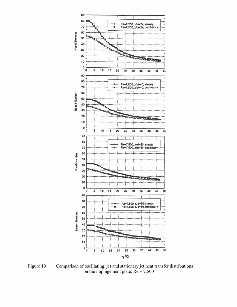
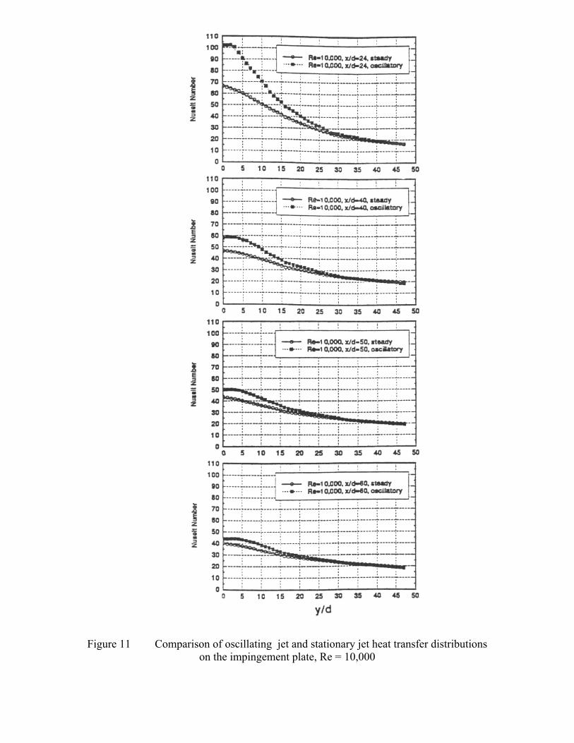
Figures 10, 11, and 12 shows significant heat transfer improvement when a stationary jet is
converted into an oscillating jet at fixed Reynolds number and impingement plate to nozzle distance.
For Re=7,500 and x/d=24, the stagnation line local Nusselt number for oscillatory impinging jet is 30
% higher than that of the stationary jet. When Reynolds number is increased to 14,000 the
enhancement from oscillations is about 71 % higher compared to stationary impinging jet, at x/d=24.
17
The heat transfer enhancement almost diminishes in the outer region of the impingement plate where
y/d>25 for all Re numbers and impingement plate to nozzle distance values. In general, the
enhancements become more pronounced as the Reynolds number is gradually increased from 7,500
to 14,000.
Comparison of heat transfer enhancements at the stagnation line: Local Nusselt numbers at
y/d=0 for both the stationary jet and the oscillating jet are given in Figures 13.a and 13.b. For the
stationary jet, at x/d=30, the stagnation point Nusselt number is about 20 % less than the case for
x/d=24 regardless of the Re number of the jet. For larger spacing, where x/d>40 (40,50,60),
dependence of Nusselt number on x/d becomes weaker as shown in Figure 13.a. At large nozzle to
impingement plate distances, flow near the stagnation point is influenced from ambient air
entrainment at a more significant rate compared to short x/d cases. All of the current heat transfer
measurements show that Nusselt number levels at the stagnation point are drastically increased,
when the stationary jet is switched into its oscillating mode, Figure 13.b. The enhancement rate has
a slight Re number dependency. However, x/d dependency at a given Re number is much stronger.
When x/d<40, oscillation induced enhancements are all greater than 30 % in reference to the
stationary jet Nusselt number values. Figure 13.c summarizes the relative heat transfer
enhancement values in reference to the stationary jet for all Re numbers and x/d values. The
minimum enhancement from oscillations has been measured as approximately 18 % at x/d=60.
However, if one reduces the plate to nozzle distance, significant Nusselt number enhancement
values are encountered. For example at x/d=40 the enhancement from oscillations is about 30
percent. After this point, the enhancements become stronger for smaller plate to nozzle distances.
At x/d=24, there is about 70 percent heat transfer augmentation on the stagnation line for
Re=14,000.
The oscillation driven enhancements discussed in this paragraph may be explained by using
time averaged momentum and thermal energy equations as discussed in previous paragraphs. When
unsteady deterministic fluid motion governs the heat transfer process, the additional inertia forces
(oscillation stresses) due to the existence of the periodic (deterministic) flow play a significant role
in the conservation of linear momentum, equation 7. The thermal energy transfer is also influenced
because of the existence of oscillations. For the case of heat transfer, oscillation heat flux terms
18
become as significant as conventional turbulent heat flux terms in the energy conservation statement,
equation 8, Herr (1995). When x/d is small, the oscillation heat fluxes and stresses dominate the
enhancement process, since the large amount of ambient air entrainment does not affect the thermal
energy transfer process. When x/d is large, the ambient air entrainment overweighs the oscillation
heat fluxes. Thus the enhancement caused by jet oscillations become almost Re number independent.
CONCLUSIONS
It is possible to convert a stationary impinging cooling jet into a self-oscillating-impinging jetby adding two communication ports at the throat section. The unsteady travel of compression andexpansion waves in the communication loop can easily put a stationary planar jet into a flappingmode for more effective thermal transport enhancement.
Oscillation frequencies ranging from 20 Hz to 100 Hz are possible by adjusting the properlength and diameter of the communication line and the stagnation pressure in the nozzle plenumchamber.
A triple-decomposition technique applied to the instantaneous velocity field andtemperature field clearly indicates the contributions of additional fluid stresses (oscillation stress)and thermal energy transfer due to oscillatory motion (oscillation heat flux). The flapping motion ofthe jet clearly improves thermal transport near the impingement plate via the imposeddeterministic/periodic motion.
Oscillation of the jet increases convection and diffusion significantly, however the kineticenergy production is only slightly modified. Previous studies performed by the authors show thatmost of the kinetic energy is contained in the deterministic part.
For the case of oscillating-impinging-jet, the area containing the enhanced heat transfer zoneon the impingement plate is enlarged effectively when compared to the stationary jet.
Oscillating jet heat transfer results are compared against stationary jet results at threedifferent Reynolds number levels (7,500, 10,000, 14,000) at various nozzle to plate distances(x/d=24,30,40,50,60). Significant heat transfer coefficient enhancements ranging from 20 % to 70 %over the stationary jet values exist because of the oscillation motion of the impinging jet.
When the jet is put into the oscillating mode, the Reynolds number dependency of oscillatingjet heat transfer distribution can be removed by plotting Nu/Re-0.50 against y/d for a prescribed x/dvalue. The data show that at a fixed nozzle to plate distance x/d, all three heat transfer distributionsfor individual Re number values collapse into a unique curve.
19
The current heat transfer enhancement achieved suggest that it is possible to implement thepresent self-oscillating-impinging-jet concept in future turbine blade internal cooling systems, onrotating disks, in electronic equipment cooling, aircraft/helicopter de-icing systems and heatexchanger systems.
Acknowledgments
The authors would like to acknowledge the assistantship provided to Frank Herr during theexecution of this project at the Turbomachinery Heat Transfer Laboratory by the Department ofAerospace Engineering, the Pennsylvania State University. Thanks are also due to Mr. GeorgeSayers for the precision machining of Aluminum nozzles used in this study.
References
Azevedo, L.F.A., Webb, B.W., Queiroz, M., 1994 “Pulsed Air Jet Impingement Heat Transfer,” Experimental Thermaland Fluid Science, Vol.8, pp. 206-213.
Bremhorst, G., Hailye, M., and Rice, E., 1990 “ Flip-flop Jet Nozzle Extended to Supersonic Flows,” AIAA Journal,Vol.28.
Foss, J.F., 1979, “Measurements in a Large-angle Oblique Jet Impingement Flow,” AIAA Journal, Vol.17, No.8,pp:801-802.
Gardon, R., and Cobonpue, J., 1962, “ Impingement Cooling From a Circular Jet in a Cross Flow,” Proceedings of2nd International Heat Transfer Conference, pp. 719-730.
Gardon, R., and Akfirat, J. C., 1965, “ The Role of Turbulence in Determining the Heat Transfer Characteristics ofImpinging Jets,” International Journal of Heat and Mass Transfer, Vol. 8, pp. 1261-1272.
Goldstein, R. J., Behbahani, A. I., and Heppelmann, K. K., 1986, “ Streamwise Distribution of the Recovery Factorand the Local Heat Transfer Coefficient to an Impinging Circular Air Jet,” Journal of International Heat and MassTransfer, Vol. 29, No. 8, pp. 1227-1235.
Goldstein, R. J., Franchett, M. E., 1988, “ Heat Transfer From a Flat Surface to an Oblique Impinging Jet,” ASMEJournal of Heat Transfer, Vol. 110, pp. 84-90.
Goldstein, R. J., Sobolik, K. A., and Seol, W. S., 1990, “ Effect of Entrainment on the Heat Transfer to a HeatedCircular Air Jet Impinging on a Flat Surface,” ASME Journal of Heat Transfer, Vol. 112, pp. 608-611.
Goldstein, R. J., and Seol, W. S., 1991, “ Heat Transfer to a Row of Impinging Circular Air Jets Including the Effectsof Entrainment,” Journal of Heat and Mass Transfer, Vol. 34, No. 8, pp. 2133-2147.
20
Herr, F., 1995, “ Turbulent Transport in a Planar Jet with Self-Sustained Deterministic Oscillations and the Characterof Impinging Region Heat Transfer,” Ph.D. Thesis, Dept. of Aerospace Engineering, The Pennsylvania StateUniversity.
Herr, F., and Camci, C., 1994.a, “ Validation of an Analytical Model for an Unsteady Planar Jet with Self-sustainedOscillations,” AIAA paper 94-2205, 25th AIAA Fluid Dynamics Conference, June 20-23, 1994, Colorado Springs,Colorado.
Herr, F., and Camci, C., 1994.b, ” Turbulent Mixing and Transport in a Planar Jet with Self-Sustained DeterministicOscillations,” 1994 ASME Winter Annual Meeting, Chicago, Illinois, ASME bound volume AD-Vol. 40.
Hussain, A. K. M. F., and Reynolds, W. C., 1970. “ The Mechanics of an Organized Wave in Turbulent Shear Flow,” Journal of Fluid Mechanics, Vol. 41.
Kline, S. J., and McClintock, F. A., 1953, “ Describing Uncertainties in Single-Sample Experiments,” ASMEMechanical Engineering, January, 1953.
Liu, T. and Sullivan, J.P., 1996, “Heat Transfer and Flow Structures in an Excited Circular Impinging Jet,”International Journal of Jeat and Mass Transfer, Vol.39, No. 17, pp. 3695-3706.
Lueptow, R. M., Breuer, K.S., and Haritonidis, J. H., 1988, “ Computer-Aided Calibration of x-Probes Using aLook-up Table,” Experiments of Fluids, Vol. 6.
Mladin, E.C. and Zumbrunnen, D.A., 1997, “Local Convective Heat Transfer to Submerged Pulsating Jets,”International Journal of Heat and Mass Transfer, Vol. 40, No. 14, pp.3305-3321.
Page, R.H., Chinnock, P.S. and Seyed-Yagoobi, J., 1996, ”Self-Oscillation Enhancement of Impingement Jet HeatTransfer,” AIAA Journal of Thermophysics, Vol.10, No.2, pp.380-382.
Panchapakesan, N. R., and Lumley, J. L., 1993, “ Turbulence Measurements in Axisymmetric Jets of Air and Helium,Part 1. Air Jet,” Journal of Fluid Mechanics, Vol. 246.
Raman, G., Hailye, M., and Rice, E., 1993, “ Flip-flop Jet Nozzle Extended to Supersonic Flows,” AIAA Journal,Vol. 31.
Wiedner, B.G. and Camci, C., 1996, “ Determination of Convective Heat Flux on Steady-State heat Transfer Surfaceswith Arbitrarily Specified Boundaries,“ ASME Journal of Heat Transfer, ASME Journal of Heat Transfer, Vol.118,pp:101-107.
21
LIST OF FIGURES
Figure 1 A planar jet with self-sustained oscillations
Figure 2 Geometrical details of the nozzle and the experimental setup for the self-oscillating impinging jet experiments
Figure 3 Heat transfer surface construction
Figure 4 Effect of nozzle throat width and communicating tube length on oscillation frequencyof the jet, (φ=20o)
Figure 5 Axial, lateral mean velocity profiles and Reynolds stresses in oscillating jet
Figure 6 Stationary jet Nusselt number distributions on impingement plate, influence ofReynolds number and impingement plate location x/d, baseline data set
Figure 7 Impingement plate heat transfer distribution from stationary jet, Nu/Re-0.56
distribution for all Reynolds numbers in function of y/d
Figure 8 Self-oscillating-jet Nusselt number distributions on impingement plate, influence ofReynolds number and impingement plate location x/d
Figure 9 Impingement plate heat transfer distribution from oscillating jet, Nu/Re-0.50
distribution for all Reynolds numbers in function of y/d
Figure 10 Comparison of oscillating jet and stationary jet heat transfer distributions on theimpingement plate, Re = 7,500
Figure 11 Comparison of oscillating jet and stationary jet heat transfer distributions on theimpingement plate, Re = 10,000
Figure 12 Comparison of oscillating jet and stationary jet heat transfer distributions on theimpingement plate, Re = 14,000
Figure 13 Stagnation line heat transfer at various nozzle to impingement plate distances, withoutand with jet oscillations
22
LIST OF CONTENTS
Abstract
Nomenclature
INTRODUCTION
EXPERIMENTAL SETUP AND PROCEDURES
Oscillating jet assemblySteady/unsteady flow field measurementsHeat transfer measurements on the target plateExperimental uncertainties
EXPERIMENTAL RESULTS AND DISCUSSION
Jet half width and effective mixingFrequency of self-sustained oscillationsAxial and lateral mean velocity componentsAdditional stresses and heat fluxes due to deterministic oscillationsHeat transfer from stationary impinging jetHeat transfer enhancement from self-oscillating-impinging-jetComparison of heat transfer enhancements at the stagnation line
CONCLUSIONS
Acknowledgments
References
Figure 1 Nozzle issuing a planar jet with self sustained oscillations
Figure 2 Geometrical details of the nozzle and the experimental setupfor the self-oscillating-impinging-jet experiments
Figure 3 Heat transfer surface construction
Figure 4 Effect of nozzle throat width and communicating tube lengthon oscillation frequency of the jet, φ=20o
Figure 5 Axial, lateral mean velocity profiles and Reynolds stresses in the oscillating jet
Figure 6 Stationary jet Nusselt number distributions on impingement plate,influence of Reynolds number and impingement plate location x/d, baseline data set
Figure 7 Impingement plate heat transfer distribution from stationary jet, Nu/Re-0.56
distribution for all Reynolds numbers in function of y/d
Figure 8 Self-oscillating-jet Nusselt number distributions on impingement plate,influence of Reynolds number and impingement plate location x/d
Figure 9 Impingement plate heat transfer distribution from oscillating jet,Nu/Re-0.50 distribution for all Reynolds numbers in function of y/d
Figure 10 Comparison of oscillating jet and stationary jet heat transfer distributionson the impingement plate, Re = 7,500
Figure 11 Comparison of oscillating jet and stationary jet heat transfer distributionson the impingement plate, Re = 10,000
Figure 12 Comparison of oscillating jet and stationary jet heat transfer distributionson the impingement plate, Re = 14,000
Figure 13 Stagnation line heat transfer at various nozzle to impingement plate distances,without and with jet oscillations