FORENSIC INVESTIGATION OF PAVEMENT FAILURES DUE TO MOISTURE ON INTERSTATE HIGHWAYS IN OREGON Paper Submitted to Transportation Research Board 88 th Annual Meeting, 2009 Washington DC by Todd V. Scholz, Ph.D., P.E. (Corresponding Author) Assistant Professor School of Civil and Construction Engineering Oregon State University, Corvallis, OR 97331 Phone: (541) 737‐2056 ; Fax: (541) 737‐3052 E‐mail: [email protected]Elizabeth Hunt, P.E. Pavement Services Engineer Oregon Department of Transportation 800 Airport Road SE Salem, Oregon 97301 E‐mail: [email protected]and Norris Shippen Pavements and Materials Research Coordinator Oregon Department of Transportation 200 Hawthorne Ave. SE, Suite B‐240 Salem, Oregon 97301‐5192 E‐mail: [email protected]Total Words = 7,419 (Abstract − 139, Main Text − 4,780, Figures − 10@250=2,500) November 13, 2008 TRB 2009 Annual Meeting CD-ROM Paper revised from original submittal.
Transcript
FORENSIC INVESTIGATION OF PAVEMENT FAILURES DUE TO MOISTURE ON INTERSTATE HIGHWAYS IN OREGON
Paper Submitted to Transportation Research Board 88th Annual Meeting, 2009
Washington DC by
Todd V. Scholz, Ph.D., P.E. (Corresponding Author) Assistant Professor
School of Civil and Construction Engineering Oregon State University, Corvallis, OR 97331 Phone: (541) 737‐2056 ; Fax: (541) 737‐3052
Total Words = 7,419 (Abstract − 139, Main Text − 4,780, Figures − 10@250=2,500)
November 13, 2008
TRB 2009 Annual Meeting CD-ROM Paper revised from original submittal.
Scholz, Hunt, and Shippen 1
ABSTRACT
In the last several years a number of major interstate and smaller projects in Oregon exhibited significant pavement distress that appeared to be associated with moisture damage within months following a rehabilitation activity. The premature failures prompted the Oregon Department of Transportation (ODOT) to fund a study to investigate interstate highway projects to determine the conditions and mechanisms that led to the premature failures. This paper documents forensic investigations of five Oregon interstate highway projects. Field investigations as well as laboratory testing of cores obtained from four of the five projects are documented. Improper tack coat or failure, permeable dense‐graded layers, stripping, inadequate drainage, and, possibly, inadequate compaction of dense‐graded material were identified as the likely root causes of the observed rutting problems on the projects that were investigated.
TRB 2009 Annual Meeting CD-ROM Paper revised from original submittal.
Scholz, Hunt, and Shippen 2
INTRODUCTION
Problem Statement
A forensic investigation is the process by which the forensic engineering team gathers the necessary information to form the probable causes of the failure that has occurred (1). It involves “the application of the engineering sciences to the investigation of failures or other performance problems” (2), where failures are “defined as instances when a structure does not conform to design expectations” (3). Forensic investigation of pavements can help pavement engineers to determine the cause of premature failures as well as to develop appropriate rehabilitation strategies and to improve future design and construction practices (1). In determining the cause(s) of failures, the principal goal is to determine the contributory mechanism(s) related to an observed pavement failure as well as the events that may have caused the problem.
In the last several years a number of major interstate and smaller projects in Oregon exhibited significant pavement distress, primarily in the form of deep ruts of 1 in. (25 mm) or greater, within months following a rehabilitation activity (typically a mill and inlay, followed by an overlay). A limited number of investigations of the early failures revealed that moisture damage in one or more of the layers underlying the inlay was the likely cause of the observed surface distress.
The premature failures prompted the Oregon Department of Transportation (ODOT) to fund a forensic investigation study of four projects on Interstate 5 and one project on Interstate 84 to determine the conditions and mechanisms that led to the premature failures. Field investigations (site visits, personnel interviews, records reviews, and coring and trenching activities) as well as laboratory tests (specific gravity, air voids, and permeability) on cores obtained from four of the five projects were performed. ODOT contracted with Oregon State University to conduct the study and provided significant assistance with the field investigations.
Objective and Scope
The principal objective of the study was to identify sources of moisture and other conditions that led to the rutting problems observed along five interstate highway projects in Oregon. The paper documents the forensic investigations undertaken including a description of the projects evaluated, results of the field and laboratory investigations, and conclusions drawn from the investigations.
PROJECTS INVESTIGATED
Figure 1 shows the location of the projects investigated in the study. As indicated, one was located on Interstate 84 just southeast of Baker (now Baker City) in northeast Oregon, and four were located on Interstate 5 between Eugene and Medford in southwest Oregon. The following paragraphs, derived from site visits, ODOT maintenance personnel interviews, and records reviews, provide brief descriptions of the projects.
TRB 2009 Annual Meeting CD-ROM Paper revised from original submittal.
Scholz, Hunt, and Shippen 3
1
23
4 5Legend:1. Pleasant Valley – Durkee2. Cottage Grove –Martin Creek3. Anlauf – ElkheadRoad4. Garden Valley – Roberts Creek5. Vets Bridge –Myrtle Creek
Figure 1. Project Locations.
FIELD INVESTIGATIONS
Project Information (Site Visit, Personnel Interviews, Records Review Data)
1. Pleasant Valley – Durkee; Interstate 84, MP 317.5 – 327.3; Year of Rehabilitation: 1999
Rehabilitation of this section included removal of 2 in. (50 mm) of hot mix asphalt (HMA) from the travel lanes and inlaying with 2 inches (50 mm) of a 3/4 in. (19 mm) nominal maximum aggregate size (NMAS) dense‐graded, lime‐treated HMA in 1999. Originally, it was planned to overlay this with 1½ inches (40 mm) of a 1/2 in. (12.5 mm) NMAS lime‐treated SMA.
Within months of the initial rehabilitation activity (while the project was still under construction) and before the SMA wearing course was placed, several areas exhibited rutting to depths of 1 in. (25 mm) and greater. Trenching operations revealed stripping of the material and the presence of free water under the new inlay to a depth of about 5 in. (125 mm). Subsequently, 5 in. (125 mm) of material from the outside lane was removed and replaced with a 3/4 inch (19 mm) NMAS dense‐graded, lime‐treated HMA. Due to low truck traffic volumes on the inside lane, only 2 in. (50 mm) of material was removed and replaced on the inside lane. A 1½‐2 in. (40‐50 mm) SMA wearing course was placed over the entire roadway. No effort was made at the time of these activities to determine the source(s) of water that contributed to the stripping.
TRB 2009 Annual Meeting CD-ROM Paper revised from original submittal.
Scholz, Hunt, and Shippen 4
Within 6 months of final construction activities, water was observed to be seeping from longitudinal construction joints and in the wheel paths in several areas of the project. Rutting and potholes began forming in several of these areas within a short period thereafter. Additional failures have occurred to date requiring ODOT maintenance forces to grind and patch the failed areas. Several of the patches have failed as well.
2. Cottage Grove – Martin Creek; Interstate 5, MP 169.3 – 174.7; Year of Rehabilitation: 2000
Rehabilitation of this section included removal of 2 in. (50 mm) of the entire HMA surface and replacement with a 3/4 in. (19 mm) NMAS lime‐treated, open‐graded HMA in 2000.
Beginning in 2002, rutting to depths of 1 in. (25 mm) and greater began forming in isolated locations throughout the project. ODOT maintenance forces have ground and patched the distressed areas to date. Observations during these activities suggest that the underlying material was the source of the failures.
3. Anlauf – Elkhead Road; Interstate 5, MP 154.5 – 162.1; Year of Rehabilitation: 1997
Rehabilitation of this section included removal of 1 in. (25 mm) of the existing HMA surface from both shoulders and the inside lane, and 3 in. (75 mm) of the existing HMA from the outside lane. Two inches (50 mm) of a 3/4 in. (19 mm) NMAS lime‐treated, dense‐graded HMA was placed on the outside lanes to match the grade of the inside lanes. The entire surface was then overlaid with 2 in. (50 mm) of a 3/4 in. (19 mm) NMAS lime‐treated, open‐graded HMA.
Rutting to depths of 1 in. (25 mm) and greater began to form within two years following rehabilitation, principally within the inside lanes, but also in some isolated areas within the outside lanes. ODOT maintenance forces have ground and patched the distressed areas. Observations during these activities suggest that the material under the newer material was failing.
4. Garden Valley – Roberts Creek; Interstate 5, MP 117.7 – 125.0; Year of Rehabilitation: 2002
Rehabilitation of this section included removal of 2 in. (50 mm) of the existing HMA surface both travel lanes and replacement with 2 in. (50 mm) of a 3/4 in. (19 mm) NMAS dense‐graded HMA. The entire surface was then overlaid with 2 in. (50 mm) of a 3/4 in. (19 mm) NMAS open‐graded HMA in 2002.
Within approximately six months of the rehabilitation activity, rutting to depths of 1 in. (25 mm) and greater began forming in isolated areas. Additional rutting has continued to form in isolated areas to date. ODOT maintenance forces have ground and patched the distressed areas. Near the southern end of the project water was observed to be seeping out at the construction joint between the outside travel lane and paved shoulder in a few locations. Trenching operations at two locations (prior to this study) revealed that the material below the new 3/4 in. (19 mm) NMAS open‐graded HMA appeared to be stripping.
TRB 2009 Annual Meeting CD-ROM Paper revised from original submittal.
Scholz, Hunt, and Shippen 5
5. Vets Bridge – Myrtle Creek; Interstate 5, MP 109.0 – 112.5; Year of Rehabilitation: 2003
Rehabilitation of this section included removal of 3 in. (75 mm) of the entire HMA surface and replacement with 3 in. (75 mm) of a 3/4 in. (19 mm) NMAS open‐graded HMA. Full depth HMA was placed where the pavement abutted bridge ends.
Within approximately nine months following the rehabilitation activity rutting to depths of 1 in. (25 mm) and greater began to form. ODOT maintenance forces have ground and patched the distressed areas. Bleeding was evident throughout the project and fat spots were observed frequently. Trenching operations at a few locations prior to this study revealed that the material immediately under the new 3/4 in. (19 mm) NMAS open‐graded HMA appeared to be stripping.
Coring
Cores were obtained from three of the projects on Interstate 5 and from the project on Interstate 84. Inability to close down a lane along the Cottage Grove – Martin Creek project on Interstate 5 prevented OSU from obtaining cores from this project for this study. However, information about cores extracted in 1995 (prior to the rehabilitation activity in 2000) is provided herein. In all cases, the thickness of each identifiable layer and its condition (Good, Fair, or Poor) was recorded on a core log. The following paragraphs summarize observations derived from the core logs.
Pleasant Valley – Durkee (Interstate 84)
Examination of the 46 core logs revealed that, with few exceptions, most pavement layers identified in the logs were in “Good” condition. However, the core logs also indicated that ten of the 18 cores obtained from the eastbound direction and 16 of the 28 cores obtained from the westbound direction had layers (or lifts) that delaminated during extraction of the cores. Four logs for the cores obtained in the eastbound direction indicated “Heavy oil” in the top two inches. Several logs for the cores obtained in the westbound direction indicated “with voids” or “some voids” in the lower portion of the original HMA, principally in the 8 to 16 inch (200 to 800 mm) range.
Cottage Grove – Martin Creek (Interstate 5)
Cores were not obtained following the rehabilitation activity for this project. However, core logs of 25 cores (13 from the southbound direction and 12 from the northbound direction) obtained from the outside wheel path of the outside lane in 1995 (prior to the rehabilitation activity in 2000) were reviewed for this study. The logs indicated that layers (or lifts) had delaminated during extraction for all but three of the cores. For the cores obtained in the southbound direction, three core logs indicated signs of stripping at depths between about 7 and 11½ in. (180 and 290 mm), and four core logs indicated disintegrating material at depths between about 7 and 13 in. (180 and 330 mm). For the cores obtained in the northbound direction, two cores had layers with disintegrating material at depths between about 9½ and 11½ in. (240 and 290 mm).
TRB 2009 Annual Meeting CD-ROM Paper revised from original submittal.
Scholz, Hunt, and Shippen 6
Anlauf – Elkhead Road (Interstate 5)
Several years after the rehabilitation activity, twelve cores (six from the outer wheel path of the outside lane and six between the wheel paths of the outside lane) were obtained at MP 157.20. Figure 2 shows a comparison of adjacent cores characterizing the typical condition of the pavement layers. Five of the cores from the wheel path and one core from between the wheel paths had layers that delaminated during extraction of the cores. Also, as expected, voids can be seen in the open‐graded surface course and in the plant mix bituminous base (PMBB). However, voids can also be seen in the dense‐graded HMA layers, particularly for the core obtained from the outside wheel path.
Garden Valley – Roberts Creek (Interstate 5)
Two sets of twelve cores (six from the outer wheel path of the outside lane and six between the wheel paths of the outside lane) were obtained from MP 118.0 and MP 118.6 approximately 4 years after the rehabilitation activity. Figure 3 shows a comparison of adjacent cores characterizing the typical condition of the pavement layers. In most cases, the cores delaminated at a depth of approximately 11 in. (280 mm). The layer immediately below this was rated on the core logs as being in “Fair” or “Poor” condition in most cases, and stripping was identified for this layer on several of the logs.
Figure 2. Adjacent Cores Obtained from the Anlauf – Elkhead Road Project.
TRB 2009 Annual Meeting CD-ROM Paper revised from original submittal.
Scholz, Hunt, and Shippen 7
Figure 3. Adjacent Cores Obtained from the Garden Valley – Roberts Creek Project.
Vets Bridge – Myrtle Creek (Interstate 5)
Twelve cores (six in the outer wheel path of the outside lane and six between the wheel paths of the outside lane) were obtained from MP 109.9 approximately 3 years after the rehabilitation activity. The logs for the cores indicated an HMA thickness of 8½ to 10¼ in. (215 to 260 mm), with the bottom layer of these cores, at of depth of approximately 5 in. (125 mm) and greater, identified as being in “Fair” condition on eight of the twelve core logs.
Trenching
Trenches were excavated from two projects along Interstate 5 (Garden Valley – Roberts Creek and Vets Bridge – Myrtle Creek) and from the project along Interstate 84 (Pleasant Valley – Durkee). For the projects along Interstate 5, one trench was excavated from each of the projects, whereas two trenches were excavated from the project on Interstate 84. In all cases, trenches approximately 2 ft. (0.6 m) wide were excavated through all layers of the pavement structure (i.e., down to the subgrade soil) across the entire width of the outside travel lane.
Following excavation, a visual assessment was made of all of the exposed layers of the pavement structure once the water from the cutting operation had dried from the trench walls. Photographs were taken periodically throughout the approximately 2 to 2½ hours that the trenches were left open.
TRB 2009 Annual Meeting CD-ROM Paper revised from original submittal.
Scholz, Hunt, and Shippen 8
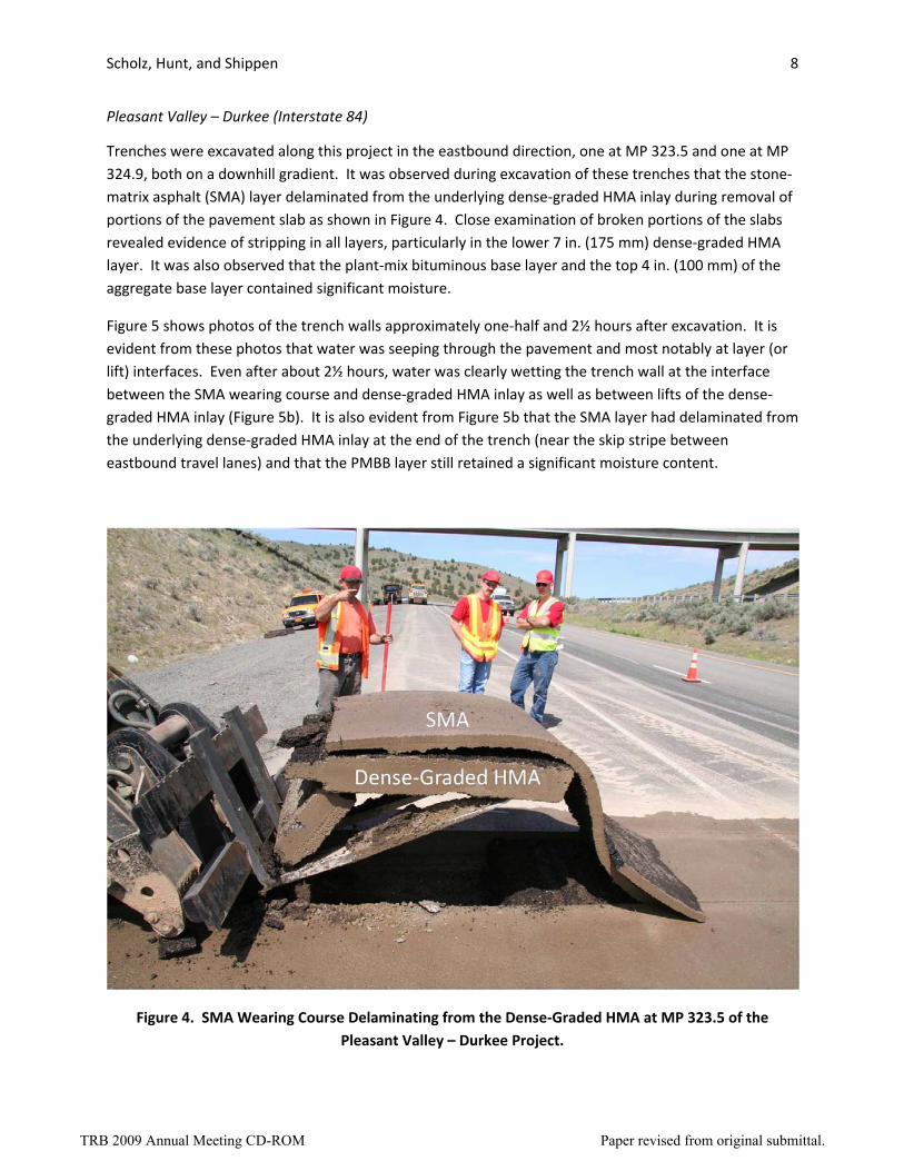
Pleasant Valley – Durkee (Interstate 84)
Trenches were excavated along this project in the eastbound direction, one at MP 323.5 and one at MP 324.9, both on a downhill gradient. It was observed during excavation of these trenches that the stone‐matrix asphalt (SMA) layer delaminated from the underlying dense‐graded HMA inlay during removal of portions of the pavement slab as shown in Figure 4. Close examination of broken portions of the slabs revealed evidence of stripping in all layers, particularly in the lower 7 in. (175 mm) dense‐graded HMA layer. It was also observed that the plant‐mix bituminous base layer and the top 4 in. (100 mm) of the aggregate base layer contained significant moisture.
Figure 5 shows photos of the trench walls approximately one‐half and 2½ hours after excavation. It is evident from these photos that water was seeping through the pavement and most notably at layer (or lift) interfaces. Even after about 2½ hours, water was clearly wetting the trench wall at the interface between the SMA wearing course and dense‐graded HMA inlay as well as between lifts of the dense‐graded HMA inlay (Figure 5b). It is also evident from Figure 5b that the SMA layer had delaminated from the underlying dense‐graded HMA inlay at the end of the trench (near the skip stripe between eastbound travel lanes) and that the PMBB layer still retained a significant moisture content.
Figure 4. SMA Wearing Course Delaminating from the Dense‐Graded HMA at MP 323.5 of the Pleasant Valley – Durkee Project.
TRB 2009 Annual Meeting CD-ROM Paper revised from original submittal.
Scholz, Hunt, and Shippen 9
a) Trench at MP 323.5 Approximately One‐Half Hour after Excavation.
b) Trench at MP 324.9 Approximately 2½ Hours after Excavation.
Figure 5. Pleasant Valley – Durkee Project Trench Walls after Excavation.
TRB 2009 Annual Meeting CD-ROM Paper revised from original submittal.
Scholz, Hunt, and Shippen 10
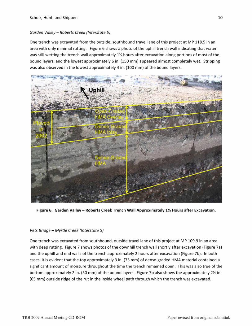
Garden Valley – Roberts Creek (Interstate 5)
One trench was excavated from the outside, southbound travel lane of this project at MP 118.5 in an area with only minimal rutting. Figure 6 shows a photo of the uphill trench wall indicating that water was still wetting the trench wall approximately 1½ hours after excavation along portions of most of the bound layers, and the lowest approximately 6 in. (150 mm) appeared almost completely wet. Stripping was also observed in the lowest approximately 4 in. (100 mm) of the bound layers.
Figure 6. Garden Valley – Roberts Creek Trench Wall Approximately 1½ Hours after Excavation.
Vets Bridge – Myrtle Creek (Interstate 5)
One trench was excavated from southbound, outside travel lane of this project at MP 109.9 in an area with deep rutting. Figure 7 shows photos of the downhill trench wall shortly after excavation (Figure 7a) and the uphill and end walls of the trench approximately 2 hours after excavation (Figure 7b). In both cases, it is evident that the top approximately 3 in. (75 mm) of dense‐graded HMA material contained a significant amount of moisture throughout the time the trench remained open. This was also true of the bottom approximately 2 in. (50 mm) of the bound layers. Figure 7b also shows the approximately 2½ in. (65 mm) outside ridge of the rut in the inside wheel path through which the trench was excavated.
TRB 2009 Annual Meeting CD-ROM Paper revised from original submittal.
Scholz, Hunt, and Shippen 11
a) Downhill View of Trench Wall Shortly after Excavation
b) Uphill and End View of Trench Walls Approximately 2 hours after Excavation.
Figure 7. Vets Bridge – Myrtle Creek Project Trench Walls.
TRB 2009 Annual Meeting CD-ROM Paper revised from original submittal.
Scholz, Hunt, and Shippen 12
LABORATORY INVESTIGATIONS
Laboratory investigations involved conducting volumetric and permeability tests on cores obtained from four of the five projects. All cores were cut into slices defined by lifts within a particular mixture type and by interfaces between mixture types. The slices were tested for bulk specific gravity, theoretical maximum specific gravity, and permeability. For the bulk specific gravity measurements, tests were conducted in accordance with ASTM D 6752 (4) using the CoreLok device to vacuum seal the test specimens in the plastic bags used in the test. Theoretical maximum specific gravity tests were conducted in accordance with AASHTO T 209 (5). Results derived from these tests were utilized to calculate air void content of the tests specimens in accordance with AASHTO T 269 (5). Permeability tests were conducted in accordance with Florida Department of Transportation Test Method FM 5‐565 (6).
Pleasant Valley – Durkee (Interstate 84)
Figure 8 shows the results of bulk specific gravity and permeability tests conducted on nine cores taken between MP 321.00 and MP 326.75 in the eastbound direction of this project. Unfortunately, theoretical maximum specific gravity tests were not conducted on these cores. Nevertheless, it can be seen from Figure 8a that, on average, the SMA layer had the greatest bulk specific gravity and that the existing HMA had the lowest bulk specific gravity. The permeability test results shown in Figure 8b indicate that, on average, the permeability of the SMA layer was much lower than that for both the HMA inlay and existing HMA layers, which had essentially identical values.
Garden Valley – Roberts Creek (Interstate 5)
Figure 9 displays the air void content and permeability test results derived from the cores obtained from MP 118.0 and MP 118.6. Figure 9a and Figure 9b indicate that the open‐graded HMA layer and the underlying dense‐graded HMA inlay layer had similar air void contents and that these were significantly higher than that of the upper lift of the existing HMA layer. They also indicate that the air void content increased with depth in the existing HMA layer. Comparing air void contents of cores obtained from within the wheel path to that of cores obtained between the wheel paths, it can be seen that only slight differences existed, except for the lowest lift at MP 118.6.
Figure 9c and Figure 9d show the permeability test results for the cores obtained at MP 118.0 and MP 118.6, respectively. As indicated, reasonable agreement existed between the results from the two locations. However, the results indicate that the open‐graded HMA overlay had permeability values not too dissimilar from those of the underlying dense‐graded HMA materials, except for the lowest layer of the existing HMA, which had a much higher value for the cores obtained from the outer wheel path at both locations.
TRB 2009 Annual Meeting CD-ROM Paper revised from original submittal.
d) Average Permeability of Pavement Layers from MP 118.6
Figure 9. Air Void Content and Permeability of Pavement Layers from the Garden Valley – Roberts Creek Project.
TRB
2009 Annual M
eeting CD
-RO
MPaper revised from
original submittal.
Scholz, Hunt, and Shippen 15
Vets Bridge – Myrtle Creek (Interstate 5)
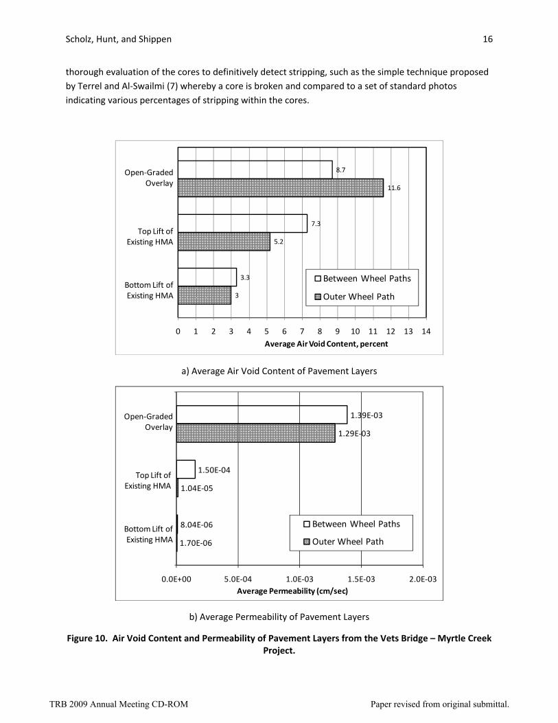
Figure 10 shows the air void content and permeability test results derived from the cores obtained from the Vets Bridge – Myrtle Creek project. Figure 10a indicates that the open‐graded HMA overlay layer had the highest air void content (although lower than expected), and air void content decreased with depth in the existing HMA layer. Comparing results derived from cores obtained in the wheel path to those of cores obtained between wheel paths, it can be seen that there is greater than 2% difference between air void contents for the open‐graded HMA overlay layer and top lift of the existing dense‐graded HMA layer, but essentially no difference for the bottom lift of the existing dense‐graded HMA layer.
The permeability test results shown in Figure 10b indicate that the open‐graded HMA overlay layer had a much higher permeability than either lift of the underlying dense‐graded HMA layer, and that the bottom lift of the dense‐graded HMA layer had a much lower permeability than the top lift of the dense‐graded HMA layer. Comparing the results shown in Figure 10a with those shown in Figure 10b, it can be seen that there appears to be a reasonable correlation between air void content and permeability of the pavement layers, with higher air void content corresponding to higher permeability.
DISCUSSION OF RESULTS
Information obtained during personnel interviews and records reviews revealed that all projects involved removal and replacement of existing dense‐graded HMA material. On two projects (Cottage Grove – Martin Creek and Vets Bridge – Myrtle Creek), the entire width of pavement was milled and replaced with an open‐graded HMA wearing course. On the other three projects, only the travel lanes were milled (to a depth greater than the adjacent shoulders and, thus, potentially creating impermeable barriers) and replaced with dense‐graded HMA, and then capped with either an SMA or an open‐graded HMA wearing course.
The personnel interviews and records reviews also revealed that all projects exhibited deep rutting—1 in (25 mm) or greater—shortly after the rehabilitation activities. Maintenance activities and preliminary investigations of these early distresses pointed to moisture damage in the layers beneath the recently‐placed material as the likely cause of the problems observed. Site visits confirmed the prevalence of wheel path patching and areas with deep rutting, but also revealed other problems including failed patches, water seepage from construction joints, and on one project, bleeding and fat spots.
In general, visual examination of cores obtained from the projects provided valuable information regarding the pavement layers such as thickness of layers and lifts, delaminated layers, presence of voids, layers with excessive asphalt binder, disintegrating layers, and evidence of stripping. Unfortunately, notations made by field crew personnel of layer conditions on the core logs did not always accurately reflect actual layer conditions. For example, the broken slabs from the trenches excavated along the Pleasant Valley – Durkee project clearly indicated the presence of stripping, whereas the core logs of cores taken in the vicinity of the trenches indicated the layers to be in “Good” condition without any notations identifying layers that had stripped (possibly due to the presence of stripping being masked by the cut circumference of the cores). This suggests the need for a more
TRB 2009 Annual Meeting CD-ROM Paper revised from original submittal.
Scholz, Hunt, and Shippen 16
thorough evaluation of the cores to definitively detect stripping, such as the simple technique proposed by Terrel and Al‐Swailmi (7) whereby a core is broken and compared to a set of standard photos indicating various percentages of stripping within the cores.
Figure 10. Air Void Content and Permeability of Pavement Layers from the Vets Bridge – Myrtle Creek Project.
TRB 2009 Annual Meeting CD-ROM Paper revised from original submittal.
Scholz, Hunt, and Shippen 17
The trenches excavated along the projects provided essentially the same information derived from the cores, but also provided additional valuable information that was not readily (or, for certain observations, could not be) obtained from cores alone. For this study, the additional information included verification of observations derived from cores taken in the vicinity of the trenches (e.g., compare Figure 3 with Figure 6), variations in structure profile along the length of the trench (e.g., rutting) and the layer(s) affected (e.g., Figure 7b), an informal assessment of moisture within the bound and subsurface layers (e.g., Figures 5‐7), and perhaps most importantly, locations where water was flowing through the structure (e.g., Figure 5‐7).
Observations made while the trenches were open along the Pleasant Valley – Durkee project on Interstate 84 clearly revealed that water was flowing through the pavement, predominately at layer and lift interfaces and, to a much lesser degree, through the layers near the interfaces (Figure 5). Notwithstanding the reported variability of the permeability test (8) utilized in this study, the results (Figure 8b) indicated relatively low water conductivity of the bound layers. These findings provide strong evidence to suggest that inadequate drainage of the pavement structure and improper tack coat or failure are the root causes of the observed stripping (and resultant rutting) problems on this project.
Observations made while the trench was open along the Garden Valley – Roberts Creek project on Interstate 5 clearly revealed water flow through the newly‐placed dense‐graded HMA inlay (Figure 6). Tests on cores taken near this trench indicated that the dense‐graded HMA inlay had an air void content of essentially equal magnitude to the open‐graded HMA overlay (Figure 9a and 9b). A similar inference can be made of the permeability test results (Figure 9c and 9d). The trench also revealed water flow through the lower portion of the existing dense‐graded HMA layer (Figure 6) corroborating the relatively high permeability test results for the cores taken from the outer wheel path (Figure 9c and 9d), but not for those taken between the wheel paths (however, it is observed that the results are of similar magnitude to those of the open‐graded HMA overlay and dense‐graded HMA inlay). Unfortunately, the air void analyses for this lowest layer present conflicting evidence with the permeability results. However, it can be seen that the lowest lift of the existing HMA layer had a much higher air void content than did the middle and upper lifts (Figure 9a and 9b). These findings provide strong evidence to suggest that inadequate drainage, stripping in the lowest portion of the bound layers and, possibly, inadequate compaction of the dense‐graded HMA inlay are the root causes of the observed rutting problems on this project.
Observations made while the trench was open along the Vets Bridge – Myrtle Creek project on Interstate 5 clearly revealed water flow through the top 2 to 3 in. (50 to 75 mm) of the existing dense‐graded HMA material (Figure 7). Tests on cores taken near this trench indicated that this layer had a higher air void content and higher permeability relative to the underlying dense‐graded material and, as expected, lower values relative to the overlying open‐graded material (Figure 10). These results provide strong evidence to suggest that inadequate drainage and, possibly, a permeable dense‐graded layer are the root causes of the observed rutting problems on this project. However, it is noted that bleeding and fat spots were observed on this project and that rutting was confined to the 3 in. (75 mm) open‐graded overlay layer where the trench was excavated (Figure 7b).
TRB 2009 Annual Meeting CD-ROM Paper revised from original submittal.
Scholz, Hunt, and Shippen 18
Based on the air void content test results presented herein, there appears to be a threshold of about 7% (based on ASTM D 6752 for determining the bulk specific gravity) above which the mixtures readily conducted water, and below which they did not. Similarly, based on the permeability results presented herein, there appears to be a threshold of about 1x10‐5 cm/sec above which the mixtures readily conducted water, and below which they did not.
CONCLUSIONS
The evidence and findings presented herein appear to warrant the following conclusions:
1. Maintenance personnel interviews and records reviews provided key information for the forensic investigations, particularly with regard to historical performance observations and maintenance activities.
2. Site visits were extremely informative with regard to verifying information obtained during the maintenance personnel interviews and record reviews, determining current pavement conditions, and scouting potential locations for further evaluations such as coring and trenching activities.
3. Visual examination of cores obtained from the projects provided valuable information regarding layer depths and conditions. However, the presence of moisture damage was not always identified from these observations suggesting a more thorough evaluation may be advisable.
4. Trenching operations revealed key information that was not readily (or, for certain observations, could not be) obtained from cores alone. Perhaps most importantly, observations of the trenches revealed water flow through or between pavement layers.
5. Results of air void analyses of the pavement layers correlated reasonably well with observations made from the trenches in that layers with relatively high air void contents were observed to conduct water, whereas layers with relatively low air void contents did not. Based on results presented herein, the threshold appears to be about 7% when ASTM D 6752 is used for determining the bulk specific gravity.
6. Results of permeability tests of the pavement layers correlated reasonably well with observations made from the trenches; that is, layers with relatively high permeability values were observed to conduct water, whereas layers with relatively low permeability values did not. Based on results presented herein, the threshold appears to be about 1x10‐5 cm/sec when the Florida DOT method is used for determining permeability.
7. Improper tack coat or failure, permeable dense‐graded layers, stripping, inadequate drainage, and, possibly, inadequate compaction of dense‐graded material were all identified as the likely root causes of the observed rutting problems on the projects that were trenched.
TRB 2009 Annual Meeting CD-ROM Paper revised from original submittal.
Scholz, Hunt, and Shippen 19
REFERENCES
1. Victorine, T.A., Zhang, Z., Fowler, D.W., and Hudson, R.W., “Basic Concepts, Current Practices, and Available Resources for Forensic Investigations on Pavements,” Research Report 1731‐1, Center for Transportation Research, The University of Texas at Austin, September, 1997.
2. American Society of Civil Engineers, Forensic Engineering: Learning from Failures, New York, N.Y., 1986.
3. Feld, J. and Carper, K., Construction Failure, 2nd Edition, John Wiley & Sons, New York, N.Y., 1997.
4. Annual Book of ASTM Standards, Vol. 04.03, West Conshohocken, PA, 2007.
5. Standards and Specifications for Transportation Materials and Methods of Sampling and Testing, 27th Edition, American Association of State Highway and Transportation Officials, Washington, D.C., 2007
6. Florida Method of Test for Measurement of Water Permeability of Compacted Asphalt Paving Mixtures, Designation FM 5‐565, Florida Department of Transportation, January 26, 2006.
7. Terrel, R.L. and Al‐Swailmi, S, “Water Sensitivity of Asphalt‐Aggregate Mixes: Test Selection,” SHRP‐A‐403, Strategic Highway Research Program, National Research Council, Washington, D.C., June 1994.
8. McGhee, K.K., Hughes, C.S., and Maupin Jr., G.W., “A Prototype Statistical Quality Assurance Specification for Acceptance of Hot‐Mix Asphalt Pavement,” Paper No. 08‐1483, Compendium of Papers, 87th Annual Meeting of the Transportation Research Board, Washington, D.C., 2008.
ACKNOWLEDGEMENTS
The Authors gratefully acknowledge financial support from the Federal Highway Administration and the Oregon Department of Transportation for the research project from which this paper was developed.
TRB 2009 Annual Meeting CD-ROM Paper revised from original submittal.