Perception & Psychophysics /993, 54 (5), 665-674 Foreshortening and the perception of parallel projections ANDREA L, NICHOLLS McMaster University, Hamilton, Ontario, Canada and JOHN M. KENNEDY University of Toronto, Toronto, Ontario, Canada Does picture perception follow polar projective geometry? Parallel projection drawings, which are not produced by using rules of polar projection, are widely regarded as visually acceptable representations of three-dimensional (3-D)objects in free viewing. One explanation is that they are perceived by means of a system in which there is no foreshortening. If so, edges of a 3-D block in 1:1 proportions should be denoted by lines in 1:1 proportions on the picture surface. However, three experiments suggest that the perception of parallel projections of a block involves foreshort- ening. In Experiment 1, 90 subjects were shown a set of parallel projections of a cube, in which each drawing depicted three sides of the cube, drawn as a square with obliques-a frontal square with receding edges shown by parallel obliques ofvarious lengths. The subjects preferred a drawing with a receding side length that was considerably foreshortened in relation to the front side. In Experiments 2 and 3, subjects viewed drawings of three blocks that differed in the ratios of the lengths of their receding edges to their frontal edges (1:1,1:2, and 1:0.65). In Experiment 2, the subjects were shown square-with-obliques drawings of the three blocks with receding edges shown by parallel obliques of various lengths. Again, the subjects preferred drawings with a receding side that was foreshortened. In Experiment 3, the drawings showed two sides of a block. The reced- ing dimension was drawn with parallel or converging lines. The preferred foreshortening was not a fixed ratio ofthe dimensions of the 3-D blocks. We suggest that square-with-obliques paral- lel projections showing cubes are taken by vision to be approximations to projections using fore- shortening. We suggest also that as the line showing the receding edge elongates, foreshorten- ing becomes less of a factor, Parallel projection systems have been used extensively to depict three-dimensional (3-D) objects and scenes in free viewing. Early Greek, Roman, Byzantine, Persian, and Chinese art all provide instances of the use of paral- lel projection (Arnheim, 1974; Dubery & Willats, 1983; Hagen, 1985, 1986). Research in drawing development also indicates that parallel projections are widespread. Many older children (10 years and above) and adults pro- duce a square with parallel oblique lines when asked to draw a cube (Arnheim, 1974; Caron-Pargue, 1985; Cox, 1986; Freeman, 1980, 1986; Willats, 1981, 1984). But the widespread use of parallel projection to represent three dimensions suggests problems for theories which contend that the perception of depth in pictures follows the laws of polar projective geometry. Parallel projection draw- We thank the Ontario Science Centre for providing invaluable test- ing facilities. We are grateful to Lauren Barnes and Richard MacLaren for their assistance with data collection. A. Nicholls is at the Schnur- macher Institute for Vision Research, SUNY/State College of Optom- etry, 100 East 24th St., New York, NY 10010. J. M. Kennedy is at the Department of Psychology, Life Sciences Division, University of Toronto/Scarborough College, 1265 Military Trail, Scarborough, ON, Canada MIC IA4. ings are not produced according to polar projection rules. Indeed, explanations for the success of parallel projec- tion drawings are often couched in terms of the observer's knowledge about the structure and features of the 3-D ob- ject (Cox, 1986; Duthie, 1985; Freeman, 1986, 1987), rather than the optic projection from the picture. In the face of this knowledge-based view, we suggest that the perception of parallel projection drawings of cubes is re- lated to how well they reenact what is projected from the 3-D object to a specific vantage point. In three experi- ments, we use one aspect of vantage-point geometry, fore- shortening, to test the hypothesis that polar projective geometry is involved in the perception of parallel projec- tions. We also suggest an important role for knowledge- based theory in the depiction of noncubic objects. The geometrical rules for the construction of polar pro- jection drawings assume an observer with his/her eye at a fixed position and fixed distance from the scene (Kubovy, 1986; Pirenne, 1970; White, 1967). This fixed vantage- point assumption has several important implications. Only the faces of the 3-D object visible from a vantage point are represented in the drawing. Also, lines in the draw- ing that show receding parallel edges of the 3-D object converge, and, if they are extended, they meet at points 665 Copyright 1993 Psychonomic Society, Inc.
Transcript
Perception & Psychophysics/993, 54 (5), 665-674
Foreshortening and the perceptionof parallel projections
ANDREA L, NICHOLLSMcMaster University, Hamilton, Ontario, Canada
and
JOHN M. KENNEDYUniversity of Toronto, Toronto, Ontario, Canada
Does picture perception follow polar projective geometry? Parallel projection drawings, whichare not produced by using rules of polar projection, are widely regarded as visually acceptablerepresentations of three-dimensional (3-D) objects in free viewing. One explanation is that theyare perceived by means of a system in which there is no foreshortening. If so, edges of a 3-D blockin 1:1 proportions should be denoted by lines in 1:1 proportions on the picture surface. However,three experiments suggest that the perception of parallel projections of a block involves foreshortening. In Experiment 1, 90 subjects were shown a set of parallel projections of a cube, in whicheach drawing depicted three sides of the cube, drawn as a square with obliques-a frontal squarewith receding edges shown by parallel obliques of various lengths. The subjects preferred a drawingwith a receding side length that was considerably foreshortened in relation to the front side. InExperiments 2 and 3, subjects viewed drawings of three blocks that differed in the ratios of thelengths of their receding edges to their frontal edges (1:1,1:2, and 1:0.65). In Experiment 2, thesubjects were shown square-with-obliques drawings of the three blocks with receding edges shownby parallel obliques of various lengths. Again, the subjects preferred drawings with a recedingside that was foreshortened. In Experiment 3, the drawings showed two sides of a block. The receding dimension was drawn with parallel or converging lines. The preferred foreshortening wasnot a fixed ratio ofthe dimensions of the 3-D blocks. We suggest that square-with-obliques parallel projections showing cubes are taken by vision to be approximations to projections using foreshortening. We suggest also that as the line showing the receding edge elongates, foreshortening becomes less of a factor,
Parallel projection systems have been used extensivelyto depict three-dimensional (3-D) objects and scenes infree viewing. Early Greek, Roman, Byzantine, Persian,and Chinese art all provide instances of the use of parallel projection (Arnheim, 1974; Dubery & Willats, 1983;Hagen, 1985, 1986). Research in drawing developmentalso indicates that parallel projections are widespread.Many older children (10 years and above) and adults produce a square with parallel oblique lines when asked todraw a cube (Arnheim, 1974; Caron-Pargue, 1985; Cox,1986; Freeman, 1980, 1986; Willats, 1981, 1984). Butthe widespread use of parallel projection to represent threedimensions suggests problems for theories which contendthat the perception of depth in pictures follows the lawsof polar projective geometry. Parallel projection draw-
We thank the Ontario Science Centre for providing invaluable testing facilities. We are grateful to Lauren Barnes and Richard MacLarenfor their assistance with data collection. A. Nicholls is at the Schnurmacher Institute for Vision Research, SUNY/State College of Optometry, 100 East 24th St., New York, NY 10010. J. M. Kennedy is atthe Department of Psychology, Life Sciences Division, University ofToronto/Scarborough College, 1265 Military Trail, Scarborough, ON,Canada MIC IA4.
ings are not produced according to polar projection rules.Indeed, explanations for the success of parallel projection drawings are often couched in terms of the observer'sknowledge about the structure and features of the 3-D object (Cox, 1986; Duthie, 1985; Freeman, 1986, 1987),rather than the optic projection from the picture. In theface of this knowledge-based view, we suggest that theperception of parallel projection drawings of cubes is related to how well they reenact what is projected from the3-D object to a specific vantage point. In three experiments, we use one aspect of vantage-point geometry, foreshortening, to test the hypothesis that polar projectivegeometry is involved in the perception of parallel projections. We also suggest an important role for knowledgebased theory in the depiction of noncubic objects.
The geometrical rules for the construction of polar projection drawings assume an observer with his/her eye ata fixed position and fixed distance from the scene (Kubovy,1986; Pirenne, 1970; White, 1967). This fixed vantagepoint assumption has several important implications. Onlythe faces of the 3-D object visible from a vantage pointare represented in the drawing. Also, lines in the drawing that show receding parallel edges of the 3-D objectconverge, and, if they are extended, they meet at points
665 Copyright 1993 Psychonomic Society, Inc.
666 NICHOLLS AND KENNEDY
termed vanishing points. Hence, measures of angles ina drawing mayor may not be equal to the measures ofcorresponding angles in a 3-D object. For example, the90 0 angles in a 3-D cube may be depicted as more acuteor obtuse in the drawing on the page, in keeping with thevisual directions of the edges of the cube from the vantage point.
As D, the distance to the object from the vantage point,increases, 0, the angle subtended by the object, decreasesfollowing a tangent law: tan 0 = HID, where H is theheight of the object. As the ties of a railroad track recede, they subtend smaller angles. A picture of the tiesuses shorter lines-foreshortened lines-to indicate increase in distance. The tracks are said to converge. Thepicture can create the same pattern at its correct vantagepoint as the real scene.
The system of parallel projection, however, does notrequire a unique, fixed vantage point. Parallel projectiondrawings have no vanishing points, save at infinity. Linesrepresenting receding edges of the object are shown asparallels. Also, some parallel projection drawings (e.g.,cavalier oblique projection; see Dubery & Willats, 1983)preserve proportionsof line lengths, whether the edge theyare showing is frontal or receding. That is, if two sidesof an object have the same metric length, as in the 1:1proportions of edges in a cube, they are represented by1:1 proportions in the lines denoting them on the page(see Figure I, top). There is no variation in line lengthto indicate the distance from the edge of the cube to theobserver. We should point out that other types of parallel projection drawings may have lines of different lengthson the page, to show the receding sides of an object. Cabinet oblique projection, for example, uses half lengths toindicate receding sides (Dubery & Willats, 1983). Notice that cabinet oblique projection preserves some of theparallels present in a 3-D cube, but also includes foreshortening, an aspect of vantage-point geometry (see Figure 1, bottom).
Figure 1. Two types of oblique projection in square-with-obliquesdrawings of cubes: cavalier oblique projection (top), and cabinetoblique projection.
In parallel projections, the fixed vantage-point assumption is not used to re-create the optic geometry projectedby a 3-D object. Why, then, are parallel projections sowidely advocatedas acceptable and visually successful depictions of 3-D objects and scenes?
One explanationis that parallel projectiondrawings maybe successful to the extent that they entail properties onthe picture surface that concur with knowledge of3-D object structure (Arnheim, 1974; Cox, 1986; Duthie, 1985;Freeman, 1986). Consider the cube drawings in Figure I.They are of a type commonly produced by subjects askedto draw a cube. We will call them square-with-obliquesdrawings. A square represents a face of the cube parallelto the picture plane, and parallel obliques of variouslengths are used to show receding sides of the cube. Arnheim (1974) describes this kind of drawing as looking"cube-like" because its properties on the picture surfacepreserve parallelism, an "essential objective property"of a 3-D cube.
Cox (1986) asked 26 undergraduates to draw a cubefrom memory. All produced a square-with-obliques version. She suggests that they may have found this to bea "good" representation of a cube because it preservesknown "facts" about cubes. Even when adults were askedto draw a cube as they saw it from a specific vantage point(where only the top and front faces were visible), many ofthem used parallel lines to represent receding edges ofthe cube. Cox's explanation was that "their knowledgeof invariant properties of the cube was so dominant thatit interfered with or even prevented any attempt to capture the fleeting look of the cube from their particular arbitrary viewpoint" (p. 345).
Freeman (1986) supported this knowledge-based interpretation of square-with-obliques drawings of cubes. Hehas described the square-with-obliques drawing as specifying "the structural description of a cube" without capturing its appearance (p. 317). He reasons that it is anacceptable representation of a cube because it is a compromise between appearance and structure. Freeman alsoconsiders aspects of the drawing that match those of a3-D cube. For instance, he says that' 'all pairs of parallelsare preserved" and that "side lengths are in constant proportion, as in a real cube" (pp. 317-318). Duthie (1985)has also described the square-with-obliques drawing asa compromise between knowledge and appearance. Hesays that it can "depict at least some right angles as rightangles, and, all parallel lines as parallel and show threesides in correct relative size" (p. 110).
Unfortunately, although it is obvious that some properties of the square-with-obliques drawing correspond tothe known structure of cubes, it is not certain that subjects use these features, or what might influence possiblecompromises, or what creates the appearance of a 3-Dcube. The parallel lines in the drawing could representa known relationship between the sides ofa cube, or theycould create the visual appearance of a real cube. Similarly, the constant proportion of side lengths might represent the proportions of sides as we know them to be
FORESHORTENING OF PARALLELS 667
MethodSubjects. The 90 subjects ranging in age from 14 to 55 volun
teered to participate at the Ontario Science Centre. All had normalor corrected-to-normal vision. Sixty-six of the participants wereshown Set 1 drawings, and 24 participants were shown a similar,redrawn set (Set 2). Two sets were used to control for any minorvariations in the drawings that might have arisen in sketching witha ruler.
Stimuli. The stimuli consisted of square-with-obliques line drawings varying in the length of the oblique lines showing the receding dimension (Figure 3). The front square in each drawing measured 2.2 x 2.2 cm. Each subject was shown four drawings, withforeshortening ratios of 1:0.38, 1:0.65, 1:0.73, and 1:0.81. (Theseratios varied slightly from their counterparts in the preliminary experiment, because the drawings were redrawn at a new size, withthinner lines.)
Three different versions of the drawings were produced. In oneversion, the oblique lines met the horizontal at 45°. In a secondversion, this angle was 30°, and in a third, it was 60°. There werefour randomized orders of the drawings for each version. A second set of the 12 drawings (Set 2) was created to verify the results,since small deviations in line length (about 0.1 em) occur as a result of the drawing technique.
Procedure. Participants were tested individually. Each subjectwas seated at a table and given a small booklet containing the in-
EXPERIMENT 1
of the angle at which the oblique line met the horizontal.The foreshortening ratios for the four drawings selectedmost often by subjects were used in Experiment I.
Figure 2. Nine square-with-obliques drawings, varying in foreshortening ratio, used in the preliminary experiment.
in a real cube, or they might create a percept of sides asthey look in a real cube. Also, it is not obvious whetherangles on the page match what we know about the properties and features of a cube, or result from vantage-pointgeometry and actually help re-create the appearance ofa cube.
Interestingly, Cox (1989) and Freeman (1986) agreethat the obliques in square-with-obliques drawings mayreflect vantage-point geometry. Cox (1989) conjecturesthat the oblique lines in the square-with-obliques drawing are included to influence the appearance of the depicted cube. Freeman (1986) points out that the obliqueline may be used to represent the direction of an edge ofa 3-D cube from the viewer. Similarly, Nicholls andKennedy (1992), in a study of drawings of cubes producedby subjects of various ages (5-year-olds to adults), suggested that older children and adults may produce squarewith-obliques drawings while trying to match the projections of parts of the 3-D cube to a vantage point. Nichollsand Kennedy found that the use of foreshortening increased with age. If the use of parallel projection is influenced by vantage-point geometry, nonfrontal edgesshould be shown with foreshortened lines on the page.
We examined examples published by theorists writingabout cube drawings, especially those from theorists writing about a knowledge-based account (Arnheim, 1974;Caron-Pargue, 1985; Cox, 1986; Deregowski & Strang,1986; Freeman, 1986, 1987; Mitchelmore, 1987; Moore,1987; Phillips, Hobbs, & Pratt, 1978; Willats, 1984).Only I of 10 cube figures, that ofWillats (1984), had thefront-line-to-side-line ratio of 1:1 that a knowledge-basedview would suggest. Both Amheim (1974) and Cox (1986)showed examples of figures with a 1:0.72 ratio. Freeman's (1986, 1987) figures have ratios of 1:0.75. Theseratios illustrate our point. Instead of depicting proportionsthat match the known 1:1 proportions of a 3-D cube, thefigures contain foreshortening. The use of foreshortening may engender the visual appearance of 1:1 proportions for a 3-D cube and reflect the influence of vantagepoint geometry.
In Experiment 1, we tested preferences for square-withobliques drawings of cubes showing different degrees offoreshortening. The stimuli were chosen on the basis ofa preliminary study with 67 volunteers (ranging in agefrom 9 to 66) at the Ontario Science Centre, who wereshown nine square-with-obliques drawings of cubes withfront-line-to-side-line foreshortening ratios ranging from1:0.32 to 1:1.5 (Figure 2). In the preliminary study, threesets of nine were used, which differed in the angle atwhich the front horizontal line of the square met the obliqueline representing the receding side (30°,45°, and 60°).
While seated at a table, the subjects in the preliminarystudy were given a booklet containing the instructions andstimuli to examine in free viewing. They were asked tocircle the best drawing of a cube from the set of ninesquare-with-obliques figures. The square-with-obliquesfigure with a front-line-to-side-line ratio of I :0.62 waspreferred by over half the subjects (Table I), irrespective
668 NICHOLLS AND KENNEDY
Angle ofOblique
30°45°60°
Total
1.1
oooo
15
oooo
structions and the stimuli, along with a pencil. Their task was toselect the best drawing of a cube and write' 'best" under the drawing. Then each subject was asked to decide which of three remaining figures was "second best" and finally to select the "worst"drawing of a cube. These written responses were assigned numerical rankings for data analysis.
ResultsTable 2 presents the mean of the rankings assigned to
the four drawings for the three angles of obliqueness. Forall three angles, the ratio receiving the highest mean ranking was 1:0.65. The 1:0.73 ratio drawing always receivedthe second highest ranking. The 1:0.38 ratio drawing hadthe lowest mean ranking for 30° and 45°, while the 1:0.81ratio had the lowest mean for 60°. A Friedman two-wayanalysis of variance showed the ratio effect to be significant [X2(4, N = 3) = 8.2, p < .02].
Log-linear analyses were conducted to determine effects of set and obliqueness angle on the ratio selectedas best by each subject. The models of interest were thosetesting the effect of ratio, the effect of set on ratio selection, the effect of obliqueness angle on ratio selection,
Figure 3. Four square-with-obliques drawings, varying in foreshortening ratio, used in Experiment 1.
and the interaction of set and obliqueness angle (seeGreen, 1988). The model containing the ratio variablealone provided the best fit to the data [G2(l5, N = 90) =13.82,P < .54]. Including the factors of set or obliqueness angle or their interaction did not significantly improve model fit.
DiscussionThe subjects greatly preferred the square with obliques
with the 1:0.65 ratio as the best drawing of a cube. Theyranked the drawing with the ratio closest to 1:1, the 1:0.81ratio drawing, as the third best. Clearly, the subjectspreferred a parallel projection drawing that had considerable foreshortening, although not as much as in the1:0.38 square-with-obliques drawing, which was consistently ranked worst.
It is relevant to note here that the subjects in the preliminary study did not have the opportunity to view drawingsexhibiting foreshortening ratios between 1:0.36 (1:0.38)and 1:0.68 (l :0.65). Thus, we cannot say that the preferred 1:0.65 ratio is the single "best" ratio (though Cutting, 1986, has noted that drawings with cabinet obliqueparallel projection, which provide a 1:0.50 foreshortening ratio, "often look too thin"). The evidence here doesconfirm that the 1:1 ratio, which would be expected froma concern for knowledge of cube properties, is not highlypreferred. Instead, in a square-with-obliques drawing thatwas most successful, the receding sides had some foreshortening.
One possible explanation for these findings is that thepreferred foreshortening ratio in the square-with-obliquesdrawing reflects an illusion suffered by any obliques (e.g.,the horizontal-vertical illusion). That is, the oblique linesin the 1:0.65 ratio might actually look equal to the horizontallines, as lengths of lines on a page. However, itseems likely to us that the lines showing the receding edgesdo look noticeably shorter than those showing the sidesof the square, if one tries to see them simply as lines onthe page.
We tested this possibility with 12 undergraduates atMcMaster University in a study involving magnitude es-
FORESHORTENING OF PARALLELS 669
eye movement'>. The order of presentation of the six figureswas counterbalanced. For each display, the subjects weretold that the horizontal line was 10 units long, and theywere asked how long the oblique line was in comparison.
A 3 (figure type) x 2 (ratio) analysis of variance fora repeated measures design yielded main effects of figure type [F(2,22) = 15.69, MSe = 3.91, p < .001] andratio [F(l,11) = 89.76, MSe = 3.12,p < .001]. Therewere no significant interactions. For the hexagon and thecross-and-hexagon figures, estimates of the line length forboth the 1:0.65 ratio figure and the 1:1 figure were quiteaccurate. The mean ratios for the 1:0.65 figure wereI :0.68 for the hexagon and 1:0.73 for the cross and hexagon. For the 1:1 figure, the mean ratios were 1:1 for thehexagon and 1:1.1 for the cross and hexagon. These findings suggest that the subjects could accurately assess thelength of the oblique line in relation to the horizontal onthe page. However, for the square-with-obliques figure,the mean ratios were 1:0.91 for the 1:0.65 figure, and1:1.39 for the I: 1 figure. That is, the subjects may indeed have perceived the 1:0.65 square-with-obliquesdrawing as representing the appearance of a cube withequal-measure sides in pictorial space. The subjectspresumably saw the 1:1 equal length square-with-obliquesfigure as looking "too long" to represent the appearanceof a 3-D cube. No subjects judged the ratio in the 1:1square-with-obliques figure to be 1:1 or less. These findings provide some evidence against the notion that thepreferred ratio is due to a geometrical illusion, such asthe horizontal-vertical illusion.
We suggest that the 1:0.65 ratio reflects a concern forhow well the parallel projection drawing reenacts whatis projected from a 3-D cube to a vantage point. The lengthof the lines showing the receding sides of the cube in thedrawing is meant to produce the appearance in depth ofthe length of the sides in a 3-D cube. The implication isthat for parallel projection, vision does not rely entirelyon shapes and sizes on the picture surface: some visualprojective geometry and apparent depth seem to be involved, not knowledge about matching the length and proportions of parts of the object with the length and proportions of parts in the drawing on the page.
We are not certain why 1:0.65 (or thereabouts) is thepreferred foreshortening for a parallel projection of acube. However, a cube is a highly familiar object, andsubjects may have had access to a stereotypical or canonical representation ofa cube, which involved taking a specific vantage point. One way to test this specific vantagepoint notion is to obtain judgments about foreshorteningfor objects that are not cubes.
In Experiment 2, subjects made judgments about oneof three blocks, each with a square "front" face. Onewas a regular cube. In a second block, the length of thereceding side was 65% of the length of the frontal square.In the third block, the length of the receding side was twicethe length of the front. Our primary goal was to examinewhether the subjects would prefer square-with-obliquesdrawings of the three blocks that contained foreshortening. The use of three different lengths of receding dimen-
0.65 0.73
3.35 3.03.37 2.803.23 3.01
Foreshortening Ratio
0.38
1.681.792.02
Angle ofOblique
30°45°60°
timation. These subjects saw six line drawings, each ofwhich contained a horizontal line measuring 3.2 em andan oblique line that met the horizontal at 45 0
• Three different figures were used (Figure 4). One was a squarewith-obliques figure of a cube or box, to assess the perception of the lines in pictorial space. Two additionalpatterns containing the horizontal and oblique lines wereincluded, to test the perception of the lines on the page.One was the hexagonal outline of the cube figure. Theother also maintained the hexagonal outline of the cubefigure, but included a cross inside. For each figure, twoversions were produced. One provided a horizontal-tooblique line ratio of 1:0.65, and a second had a ratio of1:1.
The six line drawings were shown individually on vertical cards at the subjects' eye level, 1200 ern from wherethey were seated. There were no restrictions on head or
Table 2Mean Rankings for Drawings Varying in Foreshortening Ratio
for Experiment I
Figure 4. Square-with-obliques 1:1 ratio (top left), square-withobliques 1:0.65 ratio (top right), hexagon 1:1 ratio (center left), hexagOIlI:0.65 ratio (center right), cross-and-hexagon 1:1 ratio (bottomleft), and cross-and-hexagon 1:0.65 ratio (bottom right).
670 NICHOLLS AND KENNEDY
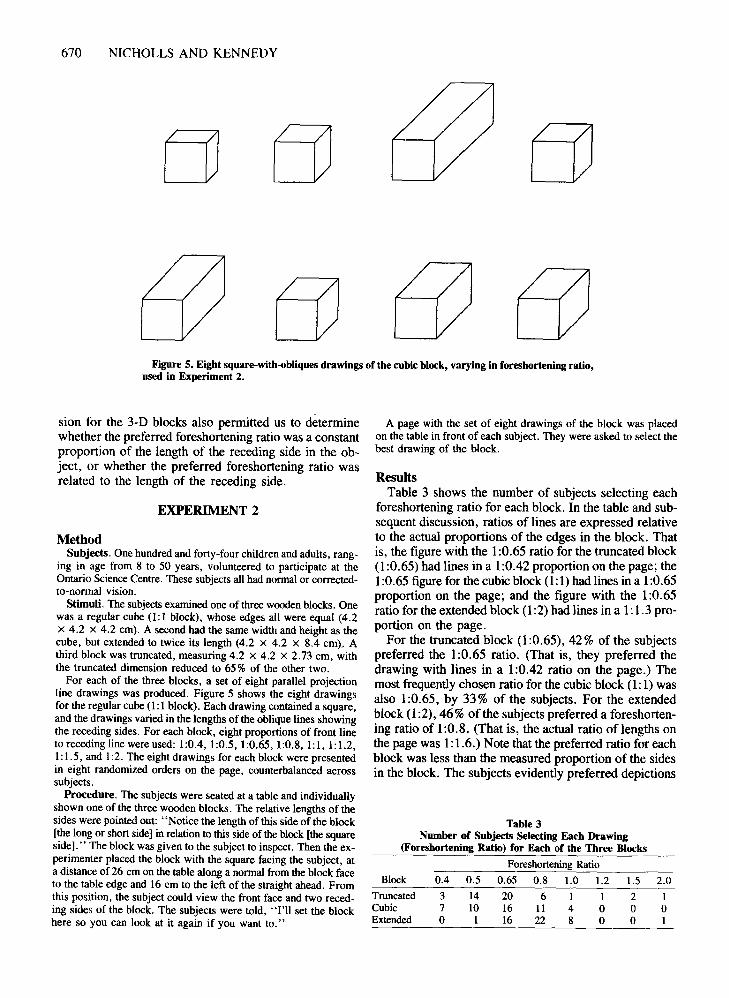
Figure 5. Eight square-with-obliques drawings of the cubic block, varying in foreshortening ratio,used in Experiment 2.
sion for the 3-D blocks also permitted us to determinewhether the preferred foreshortening ratio was a constantproportion of the length of the receding side in the object, or whether the preferred foreshortening ratio wasrelated to the length of the receding side.
EXPERIMENT 2
MethodSubjects. One hundred and forty-four children and adults, rang
ing in age from 8 to 50 years, volunteered to participate at theOntario Science Centre. These subjects all had nortnal or correctedto-normal vision.
Stimuli. The subjects examined one of three wooden blocks. Onewas a regular cube (l: 1 block), whose edges all were equal (4.2x 4.2 x 4.2 ern). A second had the same width and height as thecube, but extended to twice its length (4.2 x 4.2 X 8.4 ern). Athird block was truncated, measuring 4.2 X 4.2 X 2.73 em, withthe truncated dimension reduced to 65 % of the other two.
For each of the three blocks, a set of eight parallel projectionline drawings was produced. Figure 5 shows the eight drawingsfor the regular cube (1:1 block). Each drawing contained a square,and the drawings varied in the lengths of the oblique lines showingthe receding sides. For each block, eight proportions of front lineto receding line were used: 1:0.4,1:0.5,1:0.65,1:0.8,1:1,1:1.2,1:1.5, and 1:2. The eight drawings for each block were presentedin eight randomized orders on the page, counterbalanced acrosssubjects.
Procedure. The subjects were seated at a table and individuallyshown one of the three wooden blocks. The relative lengths of thesides were pointed out: "Notice the length of this side of the block[the long or short side] in relation to this side of the block [the squareside]." The block was given to the subject to inspect. Then the experimenter placed the block with the square facing the subject, ata distance of26 cm on the table along a nortnal from the block faceto the table edge and 16 em to the left of the straight ahead. Fromthis position, the subject could view the front face and two receding sides of the block. The subjects were told, "J'Il set the blockhere so you can look at it again if you want to."
A page with the set of eight drawings of the block was placedon the table in front of each subject. They were asked to select thebest drawing of the block.
ResultsTable 3 shows the number of subjects selecting each
foreshortening ratio for each block. In the table and subsequent discussion, ratios of lines are expressed relativeto the actual proportions of the edges in the block. Thatis, the figure with the 1:0.65 ratio for the truncated block(1:0.65) had lines in a 1:0.42 proportion on the page; the1:0.65 figure for the cubic block (1:1) had lines in a 1:0.65proportion on the page; and the figure with the 1:0.65ratio for the extended block (1:2) had lines in a 1:1.3 proportion on the page.
For the truncated block (1:0.65),42% of the subjectspreferred the 1:0.65 ratio. (That is, they preferred thedrawing with lines in a 1:0.42 ratio on the page.) Themost frequently chosen ratio for the cubic block (1:1) wasalso 1:0.65, by 33% of the subjects. For the extendedblock (1:2), 46% of the subjects preferred a foreshortening ratio of 1:0.8. (That is, the actual ratio oflengths onthe page was 1:1.6.) Note that the preferred ratio for eachblock was less than the measured proportion of the sidesin the block. The subjects evidently preferred depictions
Table 3Number of Subjects Selecting Each Drawing
(Foreshortening Ratio) for Each of the Three Blocks
of the blocks with receding sides that were foreshortenedrelative to their actual proportions. Indeed, for the cubicblock, no subjects selected ratios where the proportionof the receding side as opposed to the front side wasgreater than in the actual block; only 4 subjects did sofor the truncated block, and only I for the extended block.
Log-linear analyses were performed to assess the effects of block length and age on the selection of the foreshortening ratio. The subjects were divided into three agegroups, 8-10, 11-13, and 14 and older, with 48 subjectsin each group. The models of interest were those testingthe effect of block length on foreshortening ratio, the effect of age on foreshortening ratio, and the interactionof block length and age (see Green, 1988). The modelcontaining the main effect of block length [G 2(42, N =192) = 37.57,p < .66] provided the best fit to the data,suggesting that the preferred foreshortening ratio depended on the length of the receding side of the block.Including age effects did not improve the model fit.
While I :0.65 is the mode for the truncated block(1:0.65), more subjects (17) selected ratios below 0.65in two categories (0.4 and 0.5) than above (II subjects,in 5 categories from 0.8 to 2). A similar bias is evidentin judgments for the extended block. Preferences for thecubic block (I: I) were more evenly balanced above (15subjects) and below (17 subjects) the mode of 1:0.65.
DiscussionFor all three blocks, the subjects preferred square-with
obliques drawings that depicted front-to-side proportionsas foreshortened relative to their actual proportions in the3-D block.
The preference for foreshortening in the parallel projection drawings of the three blocks can be related to the"natural perspective" projected to a vantage point fromthe real 3-D object. In natural perspective, a cube's frontface always subtends a greater angle than does the sideface. Presumably, the subjects took the square in thesquare-with-obliques drawing to be the front face.
We should point out that in artificial perspective, whena picture of an object is present-that is, when a picturesurface is placed between the object and the vantagepoint-a far wider set of projected proportions from thedepicted convergent "side" and square "front" faces ispossible than under natural perspective. In many of theseprojections, the convergent part of the picture representing a side face is larger (and can project a much largerangle) than the square part of the picture representing thefront face (see, e.g., Pirenne, 1970, Figures 9.11B and9.11C). Since vision prefers a well-marked degree offoreshortening, vision does not use a huge range of artificialperspective ratios. We will return to this later.
Square-with-obliques showing three faces are commondrawings of cubes. Cubes can also be drawn with onlytwo faces showing, in parallel or convergent perspective.Dubery and Willats (1983) have pointed out one variantof this style, in which the front of a cube is shown as asquare and verticals are used to show the cube's topface-a style called vertical oblique. In comparison with
FORESHORTENING OF PARALLELS 671
the style used in the present Experiments I and 2, vertical oblique is uncommon in drawings of cubes made bychildren and adults (Nicholls & Kennedy, 1992). It maybe used to test for the use of foreshortening in fairly unfamiliar kinds of parallel projection drawings, and to compare judgments of parallel and convergent stimuli.
EXPERIMENT 3
MethodSubjects. Seventy-two undergraduate students participated as part
of course credit in an introductory psychology class at McMasterUniversity. All had normal or corrected-to-normal vision.
Stimuli. The subjects were shown each of the three blocks usedin Experiment I-the truncated block (l :0.65), the cubic block (l: I),and the extended block (l :2)-individually. Two sets of six linedrawings were produced for each block. In both sets, a square wasdrawn to show a side of the block facing the observer. In the parallel projection set (Figure 6), the receding top of each block wasrepresented with vertical lines. Figure 7 shows the converging projection set, in which the receding top of each block was representedwith converging, oblique lines. The angle between each of theoblique lines and the line showing the top edge of the block's frontface was 85° in each drawing. For both the parallel projection setand the converging projection set, six drawings were produced. Theratios of the line for the receding edge to the line showing the frontedge of the block were 1:0.4, 1:0.5, 1:0.65, I :0.8, and 1:1. Again,the 1:0.8 ratio for the truncated block (l :0.65) means that the lineswere in a I :0.52 proportion on the page. The same ratio for theextended block (l :2) was shown by using lines in a I: 1.6 proportion on the page. The order of presentation of the six drawings foreach block was counterbalanced across subjects.
Procedure. The subjects inspected one of the three blocks andwere instructed to notice the length of the receding side relative
Figure 6. Parallel versions of six two-sided drawings of the cubicblock, varying in the length of the vertical, parallel lines showingthe receding side.
672 NICHOLLS AND KENNEDY
I
I
Figure 7. Convergent versions of six two-sided drawings of thecubic block, varying in the length of the converging, oblique linesshowing the receding side.
to the length of the front side. The block was then placed 40 erndirectly in front of the subject on the table top, with the front squareand top of the block available to the observer. Half the subjectsselected the best drawing of the block from the set of six parallelprojection drawings, and half made their selection from the converging projection set. The procedure was then repeated for eachof the other two blocks, with the same projection set.
ResultsTable 4 shows the number of subjects selecting each
foreshortening ratio for the parallel and convergent projection sets for each of the three blocks. The preferredratios for the parallel projection drawings were significantly different from those for the converging projectiondrawings [X2(4, N = 72) = 32.79, p < .001]. In general, the preferred ratios for the parallel drawings werehigher than those for the converging drawings. For par-
Table 4Number of Subjects Selecting Each Drawing
(Foreshortening Ratio) for the Parallel Projectionand Converging Projection Sets for Each Block
allel drawings of the truncated block (1:0.65) 55% of thesubjects preferred the 1:0.8 foreshortening ratio, whereasfor the convergent drawings of the same block, themajority (61%) preferred the 1:0.5 ratio. For the cube(1:1), 50% of the subjects chose the I :0.8 ratio for theparallel drawings, and 36% chose the 1:0.5 ratio for theconvergent drawings. The preferred ratio for the paralleldrawing of the extended block (1:2) was 1: I (55 % of thesubjects), but, for the convergent drawing, the preferredratio was 1:0.65 (44% of the subjects). No subjects choseforeshortening ratios greater than 1:1 for any of the threeblocks in the parallel or convergent versions.
Each of the two drawing types (parallel and convergent)can also be considered separately for the within-subjectseffect of block length. A Friedman two-way analysis ofvariance on the parallel drawings showed that rankingsfor the three different blocks were significantly differentfrom each other [X2(2, N = 36) = 17.01,p < .01]. Rankings for the three blocks were also significantly differentfor subjects who saw the convergent drawings [X2(2, N =36) = to.51,p < .01]. While the mode of 1:0.8 for the1:0.65 block was flanked by more subjects selecting alower ratio (12 subjects) than a higher ratio (4) in the caseof the parallel projection, in the case of the cube (1: 1block) the mode was flanked by more subjects preferringa higher ratio (12 subjects) than a lower ratio (6).
DiscussionExperiment 3 was designed to test whether subjects
preferred foreshortening ratios in parallel projections ofblocks that used parallel vertical lines, rather than obliquelines, to show the receding sides. Our findings suggestthat they do. For both the truncated block and the cubicblock, the foreshortening ratio preferred by a large number of subjects was 1:0.8. However, for the extendedblock, the preferred ratio was 1: I (though no subjectspreferred a ratio above 1:1).
It is of interest that there were differences in thepreferred foreshortening ratios for the parallel and convergent versions for each block. Foreshortening ratios forthe convergent versions of the three blocks were substantially smaller than their parallel projection counterpartsI :0.5 for the truncated and cubic blocks (vs, 1:0.8), and1:0.65 for the extended block (vs. 1:1). We suggest thatthe oblique line is more effective than the parallel vertical lines in creating apparent depth.
GENERAL DISCUSSION
Why is a parallel projection drawing subject to foreshortening criteria in free viewing? And why does thepreferred foreshortening change as the block elongates?
Hagen (1985, 1986) suggests that parallel perspectiveis taken by vision to be a special kind of polar perspective. In parallel projection drawings, the 3-D object's location is so far away that light is projected to the vantagepoint in parallels. Although in theory a substantial objectmust be located at an infinite distance for reflected lightto project as parallel, Hagen (1985) suggests that in prac-
tice, for vision, optical infinity is much closer. She argues that a vantage point "assumed at a distance of 40times the size of the object is effectivelyat optical infinity"(p. 60). That is, parallel projection drawings may be takenby vision to be extreme examples of the system of polarprojection.
Consider a block held at arm's length and eye level,with its front face vertical. If the arm moves down to waistlevel, convergence of the sides of the top decreases (fora vertical picture plane). At the same time, the top sideof the block projects a larger and larger angle to the vantage point. Note that as the convergence decreases, theprojected ratio of the front to the side edge increases. Thisis precisely the relationship that the preferences in Experiment 3 follow. Parallel projection drawings requireratios closer to I: 1 than do convergent drawings, for agiven block.
Why do the preferred foreshortening ratios vary withthe length of the receding side of the block? A squarewith-obliques drawing shows a front face and a side face.It indicates that the block is not placed straight aheadthat is, with the vantage point on the normal from the middle of the front face. Rather, the vantage-point P is somewhat to one side of the front face-a location where theside face is not occluded. A cube, with each edge of length1, may project 1:0.65 to a picture plane parallel to thefront face, with vantage point P. Imagine that the cubeis now doubled by adding another cube to the rear face.What will be the projection of this addition? .
The answer is that the new addition will not require thatthe projection double. The projection will increase, butless than an additional 1:0.65. Notice that if the cube wereto extend gradually back to infinity, it is a fundamentalprinciple of polar perspective that the projection wouldincrease, but at an ever decreasing rate, to a vanishingpoint at the foot of the normal from the vantage point tothe picture surface.
The evidence from Experiments 1, 2, and 3 is that subjects violate this fundamental principle of polar perspective. Subjects use 0.65 foreshortening or more for cubesand truncated blocks, but less and less foreshortening(from 1:0.8 all the way to 1:1) for longer blocks.
It seems likely that subjects are using two principles.The selection between the principles depends on the proportions of the 3-D block. With shorter blocks, subjects'judgments involve foreshortening. Foreshortening judgments could stem from percepts of depicted objects, seenin depth, meaning that the features on the page stimulatea percept of an object in a pictorial 3-D world. The characteristics of that perceived object, not the features on thepage directly, govern the subjects' judgments. Short lineson the page are seen "in depth," as being longer thanthey are on the page. With longer blocks, subjects' judgments are based on a scan of features on the page. A lineL on the page is assessed as depicting an edge of the samelength as a line L of the same length but at an oblique to L.
The reason for the subjects' shift in criteria as blockselongate could be that short blocks depicted with foreshortening in parallel perspective are quite similar to con-
FORESHORTENING OF PARALLELS 673
vergent drawings, for objects with a small angular subtense, as Hagen (1986) noted. With longer blocks, it ispossible to have stricter criteria for parallels. If so, onlyshorter blocks are deemed to be shown using convergence,and foreshortening is relevant.
A curious implication of our interpretation here is thatArnheim, Cox, Duthie, and Freeman are incorrect as faras the object of their discussions-a cube-is concerned.Their knowledge-based thesis actually catches hold withlonger blocks. In Experiment 3, the modal preference wasa 1:1 ratio with a 1:2 block, with lines for the recedingside stretching vertically, although with a cube as the target block the subjects preferred 1:0.8.
A very important result in Experiment 3 is the shift inpreferences that occurred with convergent obliques. Theseincreased from 1:0.5 for the truncated block to 1:0.65for the cube. The principle revealed in Experiment 2'sresults helps explain demonstrations by Pirenne (1970,Figures 9.11B and 9.11C). Pirenne's drawings, shownin Figure 8, represent cubes with two or three faces confronting the viewer, with frontal squares, parallelograms,rectangles, and trapezoids (see also Kubovy, 1986). The
Figure 8. A central projection of a set of 18 cubes with the picture plane parallel to the front faces of the cubes (top) and a central projection of the same cubes with the picture plane set at a slantof 15° to the plane containing the front cube faces. From Optics,Painting and Photography (p. 127) by M. H. Pirenne, 1970, Cambridge: Cambridge University Press. Copyright 1970 by CambridgeUniversity Press. Adapted by permission.
674 NICHOLLS AND KENNEDY
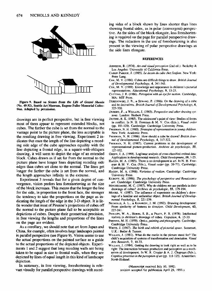
Figure 9. Based on Scenes from the Life of Gensei Shomn(No. 49.92), Seattle Art Museum, Eugene Fuller Memorial Collection. Adapted by permission.
drawings are in perfect perspective, but in free viewingmost of them appear to represent extended blocks, notcubes. The farther the cube is set from the normal to thevantage point to the picture plane, the less acceptable isthe resulting drawing in free viewing. Experiment 2 indicates that once the length of the line depicting a receding side edge of the cube approaches equality with theline depicting a frontal edge, in a square-with-obliquesdrawing, it will seem to depict the edge of an extendedblock. Cubes drawn as if set far from the normal to thepicture plane have longer lines depicting receding sideedges than cubes set close to the normal. The lines getlonger the farther the cube is set from the normal, andthe length approaches infinity in the extreme.
Experiment 3 reveals that for a given degree of convergence, vision prefers less foreshortening as the sizeof the block increases. This means that the longer the linefor the side, in proportion to the front face, the strongerthe tendency to take the proportions on the page as indicating the length of the edge in the 3-D object. It is little wonder that most of Pirenne's projections of cubes offthe normal to the picture plane fail to be acceptable asdepictions of cubes. Despite their geometrical precision,in free viewing the lengths and proportions of the lineson the page are evident.
As a corollary, we should note that art from Japan andChina, for example, often involveslarge landscapes paintedin parallel perspective (see Figure 9). Vision seems to usethe actual proportions on the painted surface as a guideto the actual proportions of the depicted objects. Experiments 1 and 2 suggest that long receding walls are beingtaken to be equal in size to frontal walls, when they aredepicted by lines of equal length in this kind of landscapedepiction.
In summary, in free viewing, foreshortening is relevant visually for parallel perspective drawings with reced-
ing sides of a block shown by lines shorter than linesshowing frontal sides, as in polar (convergent) perspective. As the sides of the block elongate, less foreshortening is required on the page for parallel perspective drawings. The reduction in the use of foreshortening is alsopresent in the viewing of polar perspective drawings asthe side lines elongate.
REFERENCES
ARNHEIM, R. (1974). An and visual perception (2nd ed.). Berkeley &Los Angeles: University of California Press.
CARON-PARGUE, J. (1985). Ledessin du cube chez l'enfant. New York:Peter Lang.
Cox, M. V. (1986). Cubes are difficult things to draw. British Journalof Developmental Psychology, 4, 341-345.
Cox, M. V. (1989). Knowledge and appearance in children's pictorialrepresentations. Educational Psychology, 9, 15-25.
CUTTING, J. E. (1986). Perception with an eye for motion. Cambridge,MA: MIT Press.
DEREGOWSKI, J. B., & STRANG, P. (1986). On the drawing of a cubeand its derivatives. British Journal ofDevelopmental Psychology, 4,323-330.
DUBERY, F., & WILLATS, J. (1983). Perspective and other drawing systems. London: Herbert Press.
DUTHIE, R. K. (1985). The adolescent's point of view: Studies of formsin conflict. In N. H. Freeman & M. V. Cox (Eds.), Visual order(pp. 101-120). Cambridge: Cambridge University Press.
FREEMAN, N. H. (1980). Strategies ofrepresentation in young children.New York: AcadeInic Press.
FREEMAN, N. H. (1986). How should a cube be drawn? British Journal of Developmental Psychology, 4, 317-322.
FREEMAN, N. H. (1987). Current problems in the development ofrepresentational picture-production. Archives de psychologie, 55,127-152.
GREEN, J. A. (1988). Loglinear analysis of cross-classified ordinal data:Applications in developmental research. ChildDevelopment, 59, 1-25.
HAGEN, M. A. (1985). There is no development in art. In N. H. Freeman & M. V. Cox (Eds.), Visual order (pp. 59-77). Cambridge:Cambridge University Press.
HAGEN, M. A. (1986). Varieties of realism. Cambridge: CambridgeUniversity Press.
KUBOVY, M. (1986). The psychology ofperspective and Renaissancean. Cambridge: Cambridge University Press.
MrrCHELMORE, M. C. (1987). Why do children not use parallels in theirdrawings of cubes? Archives de psychologie, 55, 179-194.
MOORE, V. (1987). The influence of experience on children's drawings of a familiar and unfaIniliar object. British Journal ofDevelopmental Psychology,S, 221-239.
NICHOLLS, A. L., & KENNEDY, J. M. (1992). Drawing development:From similarity of features to direction. Child Development, 63,227-241.
PHILLIPS, W. A., HOBBS, S. B., & PRATT, F. R. (1978). Intellectualrealism in children's drawings of cubes. Cognition, 6, 15-33.
PiRENNE, M. H. (1970). Optics, painting and photography. Cambridge:Cambridge University Press.
WHITE, J. (1967). The birtn and rebirtb ofpictorial space. Somerset,U.K.: Butler & Tanner.
WILLATS, J. (1981). What do the marks in the picture stand for? Thechild's acquisition of systems of transformation and denotation. VisualAns Research, 7, 18-33.
WILLATS, J. (1984). Getting the drawing to look right as well as to beright: The interaction between production and perception as a mechanism of development. In W. R. Crozier & A. J. Chapman (Eds.),Cognitiveprocesses in the perception ofan (pp. 111-125). Amsterdam:North-Holland.
(Manuscript received July 10, 1992;revision accepted for publication April 29, 1993.)


![Journal of Experimental Psychology: Human Perception and ... · independent parallel [UCIP], race model). The observed RT dis-tributions in the redundant-target condition are compared](https://static.documents.pub/doc/80x56/5e82b920c1ca966fad4769c2/journal-of-experimental-psychology-human-perception-and-independent-parallel.jpg)


