spécifications matières materials requirements composition chimique / chemical composition .......... 4-2 et 4-3 caractéristiques mécaniques mechanical properties............................................ 4-4 à 4-5 pressions et températures de service working pressure temperature rating ........................ 4-6 à 4-7 raccords en acier forgé forged steel fittings raccords à visser threaded fittings .................................................... 4-9 à 4-31 raccords à souder socket welding fittings ........................................... 4-33 à 4-45 raccords de dérivation renforcés reinforced branch fittings descriptif / description .......................................... 4-46 raccord bout à bout / butt welding fitting ................ 4-46 raccord emboîté soudé / socket welding fitting ......... 4-47 raccord taraudé / threaded fitting .......................... 4-47 raccord allongé / extended fitting ......................... 4-48 raccord incliné à 45° pour collecteur droit 45° angle fitting for straight pipe ........................... 4-48 raccord incliné pour mise en place sur coude long rayon 90° angle fitting for installation on long radius 90° elbow .......................................... 4-49 pièces spéciales de raccordement / dérivation à rayons perturbés special forged branch fittings .................................. 4-52 et 4-53 RACCORDS EN ACIER FORGÉ FORGED STEEL FITTINGS SOMMAIRE CONTENTS
Transcript
spécifications matièresmaterials requirementscomposition chimique / chemical composition .......... 4-2 et 4-3caractéristiques mécaniquesmechanical properties............................................ 4-4 à 4-5pressions et températures de serviceworking pressure temperature rating........................ 4-6 à 4-7
raccords en acier forgéforged steel fittingsraccords à visserthreaded fittings .................................................... 4-9 à 4-31raccords à soudersocket welding fittings ........................................... 4-33 à 4-45
raccords de dérivation renforcésreinforced branch fittingsdescriptif / description .......................................... 4-46raccord bout à bout / butt welding fitting ................ 4-46raccord emboîté soudé / socket welding fitting......... 4-47raccord taraudé / threaded fitting.......................... 4-47raccord allongé / extended fitting ......................... 4-48raccord incliné à 45° pour collecteur droit45° angle fitting for straight pipe ........................... 4-48raccord incliné pour mise en place surcoude long rayon 90°angle fitting for installation onlong radius 90° elbow .......................................... 4-49pièces spéciales de raccordement /dérivation à rayons perturbésspecial forged branch fittings.................................. 4-52 et 4-53
RACCORDSEN ACIER FORGÉ
FORGED STEELFITTINGS
SOMMAIRECONTENTS
CHAPITRE 4 25/08/1998 16:12 Page 1
SOMMAIRECONTENTS
4-3
spécifications matières materials requirements
4-2
< 0,35
A 350 / A 350 M – 91c
LF 3
A 182 / A 182 M – 96
F 5
Typed'acier
Acier au carboneCarbon steel
Acier alliéAlloy steel
Com
posi
tions
chim
iques
/Ch
emic
al c
om
posi
tion %
Spéc
ific
ations
A 105 / A 105 M – 96
A 350 / A 350 M – 91c
LF1
A 350 / A 350 M – 91c
LF 2
1020 1030 501
K 41545
A 48 CP A 42 AP A 48 FP 12 N 14 Z 10 CD5-05
221490
224-430LT 40
224-490LT 50
503490
625590
C 35 A St 41 St 45 N 10 Ni 14 12 CrMo 19-05
< 0,35 < 0,35 < 0,20 < 0,15
0,601,05
0,601,35
0,601,35 < 0,90 0,30
0,60
< 0,040 < 0,040 < 0,040 < 0,040 < 0,030
< 0,035 < 0,035 < 0,035 < 0,035 < 0,030
0,100,35
0,150,30
0,150,30
0,200,35 < 0,50
< 0,30 < 0,30 < 0,30 < 0,30 4,06,0
< 0,40 < 0,40 < 0,40 3,33,7 < 0,50
< 0,12 < 0,12 < 0,12 < 0,12 0,440,65
< 0,40 < 0,40 < 0,40 < 0,40
< 0,05 < 0,05 < 0,05 < 0,03
< 0,02 < 0,02 < 0,02 < 0,02
CarboneCarbon
ManganèseManganese
PhosphorePhosphorus
SoufreSulfur
SiliciumSilicon
NickelNickel
ChromeChromium
MolybdèneMolybdenum
CuivreCopper
VanadiumVanadium
NiobiumColumbium
TitaneTitanium
Niobium + TantaleColumbium + Tantalum
AISI
ASTM
Désignation UNS
AFNOR .
British StandardBS 1503 – 1980 .
DIN .
. Nuances correspondantes aux nuances ASTM indiquées pour information.Corresponding grades to ASTM grades only for information
COMPOSITION CHIMIQUE
1,001,50
CHEMICAL COMPOSITION
Acier au carboneCarbon steel
Acier alliéAlloy steel
A 182 / A 182 M–96
F 304 L
A 182 / A 182 M–96
F 316 L
A 182 / A 182 M–96
F 321
A 182 / A 182 M–96
F 347
304 L 316 L 321 347
S 30403 S 31603 S 32100 S 34700
Z 2 CN18-10
Z 2 CND17-12
Z 6 CNT18-10
Z 6 CNNb18-10
304 S 11 316 S 11 321 S 31 347 S 31
X 2 CrNi 18-09
X 2 Cr NiMo 18-10
X 10 Cr NiTi 18-09
X 10 Cr NiNb 18-09
< 0,035 < 0,035 < 0,08 < 0,08
< 2,0 < 2,0 < 2,0 < 2,0
< 0,030 < 0,030 < 0,030 < 0,030
< 0,045 < 0,045 < 0,045 < 0,045
< 1,00 < 1,00 < 1,00 < 1,00
18,0020,00
16,0018,00 > 17,00 17,00
20,00
8,0013,00
10,0015,00
9,0012,00
9,0013,00
2,003,00
> 5 C< 0,70 %
> 10 C< 1,10 %
A 182 / A 182 M–96
F 11 Cl 2
A 182 / A 182 M–96
F 22 Cl 3
K 11572 K 21590
15 CSD5-03-05
10 CD9-10
621460
622560
13 CrMo 4-4
10 CrMo 9-10
0,100,20
0,050,15
0,300,80
0,300,60
< 0,040 < 0,040
< 0,040 < 0,040
0,501,00 < 0,50
2,002,50
0,440,65
0,871,13
Type of steel
Com
posi
tions
chim
iques
/ C
hem
ical c
om
posi
tion %
Spéc
ific
ations
CarboneCarbon
ManganèseManganese
PhosphorePhosphorus
SoufreSulfur
SiliciumSilicon
NickelNickel
ChromeChromium
MolybdèneMolybdenum
CuivreCopper
VanadiumVanadium
NiobiumColumbium
TitaneTitanium
Niobium + TantaleColumbium + Tantalum
ASTM
AISI
Désignation UNS
AFNOR .
British StandardBS 1503 – 1980 .
DIN .
CHAPITRE 4 25/08/1998 16:12 Page 2
A 182 / A 182 M – 96
F 5
SOMMAIRECONTENTS
spécifications matières
4-54-4
A 182 /A 182 M–96
F 321
12 CrMo 19-05
Acier au chrome nickelStainless steel
Acier alliéAlloy steel
Typeof steel
(1) Éprouvette cylindrique ASTM 2" / Standard round specimen ASTM 2"(2) Valeurs pour éprouvettes standard (10 x 10 mm), moyenne de 3, minimum sur 1
Requirements for standard size (10 by 10 mm) specimens, average of 3, minimum for 1(3) Charpy V
A 182 /A 182 M–96
F 316 L
A 182 /A 182 M–96
F 11 Cl 2
A 182 /A 182 M–96
F 22 Cl 3
A 182 /A 182 M–96
F 304 L
304 L 316 L 321
K 11572 K 21590 S 30403 S 31603 S 32100
15 CSD5-03-05
10 CD9-10
Z 2 CN18-10
Z 2 CND17-12
Z 6 CNT18-10
621460
622560
304S 11
316S 11
321S 31
13 CrMo 4-4
10 CrMo 9-10
X 2 CrNi 18-09
X 2 Cr NiMo 18-10
X 10 Cr NiTi 18-09
A 182 /A 182 M–96
F 347
347
S 34700
Z 6 CNNb18-10347S 31
X 10 Cr NiNb 18-09
> 485 > 515 > 485 > 485 > 515
> 275 > 310 > 170 > 170 > 205
20 20 30 30 30
30 30 50 50 50
143 - 207 156 - 207
> 515
> 205
30
50
70 75 70 70 75
40 45 25 25 30
20 20 30 30 30
30 30 50 50 50
143 - 207 156 - 207
75
30
30
50
ASTM
AISI
Désignation UNS
AFNOR .
British Standard .BS 1503 – 1980
DIN .
MPa • Rm
MPa • Rp 0,2
% • A mini (1)
% • Striction mini
HB • Dureté Brinell maxi
Flexion par choc KV (2)(3)° C • (T° de l'essai)
DaJ • Énergie moy.
DaJ • Énergie mini
1000 • Tensile PSI strenght mini
1000 • Yield PSI stress mini
Elongation (1)% • mini
Reduction of% • area mini
HB • Hardness maxi
Impact test (2)(3)° F • (T° of test)
Energy /ft. lb• average
Energyft. lb• minimum
A 350 / A 350 M – 96c
LF 3
Typed'acier
Acier au carboneCarbon steel
Acier alliéAlloy steel
A 105 / A 105 M – 96
A 350 / A 350 M – 96c
LF1
A 350 / A 350 M – 96c
LF 2
1020 1030 501
K 41545
A 48 CP A 42 AP(class 1) A 48 FP(class 2) A 48 AP 12 N 14
. Nuances correspondantes aux nuances ASTM indiquées pour information.Corresponding grades to ASTM grades only for information
> 70 60 to 85 70 to 95 70 to 95 > 70
36 30 36 37.5 40
22 25 22 22 20
30 38 30 35 35
187 197 197 197 143 - 217
( – 20) Class 2 (– 0)Class 1 ( – 50) ( – 150)
> 13
> 10
Class 4 > 15Class 2 > 20
Class 1 > 12Class 2 >15
> 15
> 12
Tensile • 1000strength PSI
Yield • 1000stress mini PSI
(1) Elongationmini • %
Reduction ofarea mini • %
Hardness maxi • HB
(2)(3) Impact test(T° of test) • ° F
Energy /average • ft. lb
Energyminimum • ft. lb
> 485
Spéc
ific
ations
MECHANICAL PROPERTIES
materials requirements
Rm • MPa
Spec
ific
ations
CARACTÉRISTIQUES MÉCANIQUES
MECHANICAL PROPERTIES
CARACTÉRISTIQUES MÉCANIQUES
CHAPITRE 4 25/08/1998 16:12 Page 3
SOMMAIRECONTENTS
4-6 4-7
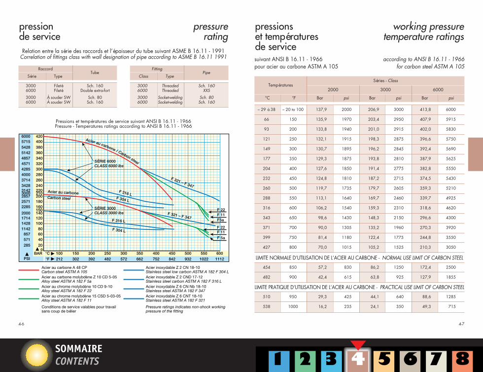
pression de service
pressure rating
pressions et températures de service
working pressure temperature ratings
Relation entre la série des raccords et l’épaisseur du tube suivant ASME B 16.11 - 1991Correlation of fittings class with wall designation of pipe according to ASME B 16.11 1991
Acier au carbone A 48 CPCarbon steel ASTM A 105Acier au carbone molybdène Z 10 CD 5-05Alloy steel ASTM A 182 F 5aAcier au chrome molybdène 10 CD 9-10Alloy steel ASTM A 182 F 22Acier au chrome molybdène 15 CSD 5-03-05Alloy steel ASTM A 182 F 11
Conditions de service valables pour travailsans coup de bélier
Acier inoxydable Z 2 CN 18-10Stainless steel low carbon ASTM A 182 F 304 LAcier inoxydable Z 2 CND 17-12Stainless steel carbon ASTM A 182 F 316 LAcier inoxydable Z 6 CN Nb 18-10Stainless steel ASTM A 182 F 347Acier inoxydable Z 6 CNT 18-10Stainless steel ASTM A 182 F 321
Pressure ratings indicates non-shock workingpressure of the fitting
Pressions et températures de service suivant ANSI B 16.11 - 1966Pressure - Temperatures ratings according to ANSI B 16.11 - 1966
suivant ANSI B 16.11 - 1966pour acier au carbone ASTM A 105
according to ANSI B 16.11 - 1966for carbon steel ASTM A 105
Températures
°C Bar°F psi Bar psi Bar psi
Séries - Class
2000 3000 6000
– 29 à 38 – 20 to 100 137,9 2000 206,9 3000 413,8 6000
66 150 135,9 1970 203,4 2950 407,9 5915
93 200 133,8 1940 201,0 2915 402,0 5830
121 250 132,1 1915 198,3 2875 396,6 5750
149 300 130,7 1895 196,2 2845 392,4 5690
177 350 129,3 1875 193,8 2810 387,9 5625
204 400 127,6 1850 191,4 2775 382,8 5550
232 450 124,8 1810 187,2 2715 374,5 5430
260 500 119,7 1735 179,7 2605 359,3 5210
288 550 113,1 1640 169,7 2460 339,7 4925
316 600 106,2 1540 159,3 2310 318,6 4620
343 650 98,6 1430 148,3 2150 296,6 4300
371 700 90,0 1305 135,2 1960 270,3 3920
399 750 81,4 1180 122,4 1775 244,8 3550
427 800 70,0 1015 105,2 1525 210,3 3050
454 850 57,2 830 86,2 1250 172,4 2500
482 900 42,4 615 63,8 925 127,9 1855
510 950 29,3 425 44,1 640 88,6 1285
538 1000 16,2 235 24,1 350 49,3 715
LIMITE NORMALE D’UTILISATION DE L’ACIER AU CARBONE - NORMAL USE LIMIT OF CARBON STEEL
LIMITE PRATIQUE D’UTILISATION DE L’ACIER AU CARBONE - PRACTICAL USE LIMIT OF CARBON STEEL
CHAPITRE 4 25/08/1998 16:13 Page 4
SOMMAIRECONTENTS
4-9
RACCORDS À VISSER
THREADED FITTINGS
CHAPITRE 4 25/08/1998 16:13 Page 5
SOMMAIRECONTENTS
4-114-10
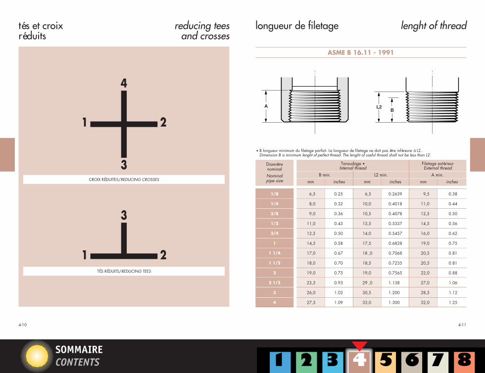
tés et croixréduits
reducing teesand crosses
longueur de filetage lenght of thread
2
4
31
2
31
4
3
21
3
21
CROIX RÉDUITES/REDUCING CROSSES
TÉS RÉDUITS/REDUCING TEES
ASME B 16.11 - 1991
L2B
A
DiamètrenominalNominalpipe size mm inches mm inches mm inches
Taraudage ,Internal thread
Filetage extérieurExternal thread
B min. L2 min. A min.
6,5 0.25 6,5 0.2639 9,5 0.38
8,0 0.32 10,0 0.4018 11,0 0.44
9,0 0.36 10,5 0.4078 12,5 0.50
11,0 0.43 13,5 0.5337 14,5 0.56
12,5 0.50 14,0 0.5457 16,0 0.62
14,5 0.58 17,5 0.6828 19,0 0.75
17,0 0.67 18 ,0 0.7068 20,5 0.81
18,0 0.70 18,5 0.7235 20,5 0.81
19,0 0.75 19,0 0.7565 22,0 0.88
23,5 0.93 29 ,0 1.138 27,0 1.06
26,0 1.02 30,5 1.200 28,5 1.12
27,5 1.09 33,0 1.300 32,0 1.25
1/8
1/4
3/8
1/2
3/4
1
1 1/4
1 1/2
2
2 1/2
3
4
, B longueur minimum du filetage parfait. La longueur de filetage ne doit pas être inféreure à L2.Dimension B is minimum lenght of perfect thread. The lenght of useful thread shall not be less than L2.
Engagement à la clé des filetages mâle et femelle suivant normes ANSI B 1.20.1 ou API Std 5 B.
Toutes les dimensions données ci-dessus correspondent aux normes américaines ANSI B 1.20.1 et API Standard 5 B.excepté pour les dimensions nominales 1/8” et 1/4” où E1 et L1 ne sont pas mesurées sur le même plan d’après l’APIStd 5 b. Toutefois, ces dimensions ramenées sur le même plan sont identiques.
Normal engagement between male and female threads to make tight joints according to standards ANSI B 1.20.1 orAPI Std 5 B.All the dimensions above correspond to the American Standards ANSI B 1.20.1 and API Standard 5 B except for thenominal sizes 1/8” et 1/4”, for which E1 and L1 are not measured on the same plan, according to API Std 5 B. Howe-ver, the dimensions are identical when referred to the same plan.
Dimensions suivantASME B 16-11 – 1991Dimensions according toASME B 16-11 – 1991
bouchons mâletête hexagonale
hex headplugs
SÉRIES 3000 - 6000 / CLASS 3000 Lb - 6000 Lb
H
A
H
Taraudage suivant ANSI B 1.20.1 – 1983
Thread according toANSI B 1.20.1 – 1983
Dimensions suivantASME B 16-11 – 1991Dimensions according toASME B 16-11 – 1991
DiamètrenominalNominalpipe size
3000 – 6000
A min. F nominal H min.
inches mm inchesmm inches
1/8 9,5 0.38 11,0 0.44 6 0.25
1/4 11,0 0.44 16,0 0.62 6 0.25
3/8 12,5 0.50 17,5 0.69 8 0.31
1/2 14,5 0.56 22,0 0.88 8 0.31
3/4 16,0 0.62 27,0 1.06 10 0.38
1 19,0 0.75 35,0 1.38 10 0.38
1 1/4 20,5 0.81 44,5 1.75 14 0.56
1 1/2 20,5 0.81 51,0 2.00 16 0.62
2 22,0 0.88 63,5 2.50 17 0.69
2 1/2 27,0 1.06 76,0 3.00 19 0.75
3 28,5 1.12 89,0 3.50 21 0.81
4 32,0 1.25 117,5 4.62 25 1.00
mm
CHAPITRE 4 25/08/1998 16:13 Page 10
Iuliana.Chila
Rectangle
Iuliana.Chila
Rectangle
SOMMAIRECONTENTS
4-214-20
DiamètresnominauxNominalpipe sizes
3000 – 6000
A min. F nominal G min.
inches mm inchesmm inches
3/8 x 1/4 12,5 0.50 17,5 0.69 4 0.16
1/2 x 3/8 14,5 0.56 22,0 0.88 5 0.19
1/2 x 1/4 14,5 0.56 22,0 0.88 5 0.19
3/4 x 1/2 16,0 0.62 27,0 1.06 6 0.22
3/4 x 1/4 16,0 0.62 27,0 1.06 6 0.22
1 x 3/4 19,0 0.75 35,0 1.38 6 0.25
1 x 1/2 19,0 0.75 35,0 1.38 6 0.25
1 x 1/4 19,0 0.75 35,0 1.38 6 0.25
11/4 x 1 20,5 0.81 44,5 1.75 7 0.28
11/2 x 1 20,5 0.81 51,0 2.00 8 0.31
11/2 x 3/4 20,5 0.81 51,0 2.00 8 0.31
11/2 x 1/2 20,5 0.81 51,0 2.00 8 0.31
2 x 11/2 22,0 0.88 63,5 2.50 9 0.34
2 x 1 22,0 0.88 63,5 2.50 9 0.34
2 1/2 x 2 27,0 1.06 76,0 3.00 10 0.38
3 x 2 28,5 1.12 89,0 3.50 10 0.41
4 x 3 32,0 1.25 117,5 4.62 13 0.50
4 x 2 32,0 1.25 117,5 4.62 13 0.50
mm
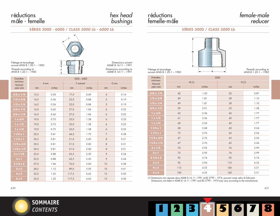
réductionsmâle - femelle
hex headbushings
SÉRIES 3000 - 6000 / CLASS 3000 Lb - 6000 Lb
G
A
F
Filetage et taraudage suivant ANSI B 1.20.1 – 1983Threads according toANSI B 1.20.1 – 1983
Dimensions suivantASME B 16-11 – 1991
Dimensions according toASME B 16-11 – 1991
réductionsfemelle-mâle
female-malereducer
SÉRIES 3000 / CLASS 3000 Lb
N
M
Filetage et taraudage suivant ANSI B 1.20.1 – 1983
Threads according toANSI B 1.20.1 – 1983
DiamètresnominauxNominalpipe sizes
3000
M (1) N (1)
inchesmm inches
3/8 x 1/4 42 1.50 22 0.87
1/2 x 3/8 49 1.81 28 1.10
1/2 x 1/4 49 1.81 28 1.10
3/4 x 1/2 59 2.01 35 1.38
1 x 3/4 63 2.36 45 1.77
1 x 1/2 61 2.36 45 1.77
1 x 1/4 60 2.36 45 1.77
11/4 x 1 68 2.68 60 2.24
11/2 x 1 72 2.76 65 2.56
11/2 x 3/4 67 2.76 65 2.56
11/2 x 1/2 67 2.76 65 2.56
2 x 1/2 70 2.95 76 2.99
2 x 1 75 2.95 76 2.99
2 1/2 x 2 92 3.74 95 3.74
3 x 2 95 3.94 110 4.33
4 x 3 113 4.33 140 5.51
4 x 2 100 4.33 140 5.51
mm
(1) Dimensions non reprises dans ASME B 16.11 –1991 et BS 3799 – 1974, pouvant varier selon le fabricant.Dimensions not listed in ASME B 16.11 –1991 and BS 3799 – 1974 may vary according to the manufacturer.
CHAPITRE 4 25/08/1998 16:13 Page 11
Iuliana.Chila
Rectangle
Iuliana.Chila
Rectangle
SOMMAIRECONTENTS
4-234-22
mamelonsréduits
reducinghexagonal nipples
SÉRIES 3000 - 6000 / CLASS 3000 Lb - 6000 Lb
b
F
WC
E
A sur platA/F Hex.
A}
Diamètre nominalNominal size
PoucesInches
mmmm mm
A(mini)
E(mini)
F(mini)
C(mini)
W(mini)
b ,
3000 6000
inc. mm inc. mm inc. mm inc. mm inc. mm inc. mm inc.
1/4 x 1/8 8 x 6 15 0.59 15 0.59 10 0.39 6 0.24 31 1.22 5 0.20 2 0.08
3/8 x 1/4 10 x 8 18 0.71 16 0.63 15 0.59 8 0.31 39 1.54 8 0.31 6 0.24
1/2 x 3/8 15 x 10 22 0.87 20 0.79 16 0.63 8 0.31 44 1.73 11 0.43 8 0.31
1/2 x 1/4 15 x 8 22 0.87 20 0.79 15 0.59 8 0.31 43 1.69 8 0.31 6 0.24
3/4 x 1/2 20 x 15 27 1.06 21 0.83 20 0.79 9 0.35 50 1.97 14 0.55 11 0.43
3/4 x 3/8 20 x 10 27 1.06 21 0.83 16 0.63 9 0.35 46 1.81 11 0.43 8 0.31
1 x 3/4 25 x 20 35 1.38 25 0.98 21 0.83 10 0.39 56 2.20 19 0.75 13 0.51
(1) Dimensions non reprises dans ASME B 16.11 –1991 et BS 3799 – 1974, pouvant varier selon le fabricant.Dimensions not listed in ASME B 16.11 –1991 and BS 3799 – 1974 may vary according to the manufacturer.
, “b” dimension nominale soumise aux tolérances normales de fabrication.Dimension “b” is nominal and is subject to normal manufacturing tolerances.
mamelons hexagonal nipples
SÉRIES 3000 - 6000 / CLASS 3000 Lb - 6000 Lb
b
E
WC
E
A sur platA/F Hex.
A}
Filetage suivant ANSI B 1.20.1 – 1983Threads according toANSI B 1.20.1 – 1983
Dimensions suivantBS 3799 – 1974
Dimensions according toBS 3799 – 1974
bossages à souder welding bosses
SÉRIES 3000 - 6000 / CLASS 3000 Lb - 6000 Lb
M
45°
N
O
K
Taraudage suivant ANSI B 1.20.1 – 1983Threads according toANSI B 1.20.1 – 1983
De 1/4” à 2” 0 = 9.5 mmFrom 1/4” à 2” 0 = 0.375 in
Diamètres nominauxNominal pipe sizes mm
3000 – 6000
inches mm inchesmm
K(1) M(1) N(1)
inches
1/4 30,5 1.20 28,0 1.10 14,0 0.55
3/8 30,5 1.20 32,0 1.26 17,4 0.69
1/2 33,5 1.32 38,0 1.50 21,6 0.85
3/4 35,0 1.38 44,5 1.75 26,9 1.06
1 43,0 1.69 57,5 2.26 33,6 1.32
1 1/4 48,0 1.89 63,5 2.50 42,4 1.67
1 1/2 51,0 2.00 76,1 3.00 48,5 1.91
2 57,5 2.26 92,0 3.62 60,9 2.40
(1) Dimensions non reprises dans ASME B 16.11 –1991 et BS 3799 – 1974, pouvant varier selon le fabricant.Dimensions not listed in ASME B 16.11 –1991 and BS 3799 – 1974 may vary according to the manufacturer.
CHAPITRE 4 25/08/1998 16:13 Page 13
SOMMAIRECONTENTS
4-27
90° streetelbows
4-26
coudes mâle-femellesà 90°
union elbowsunion tees
coudes uniontés union
(1) Dimensions non reprises dans ASME B 16.11 –1991 et BS 3799 – 1974, pouvant varier selon le fabricant.Dimensions not listed in ASME B 16.11 –1991 and BS 3799 – 1974 may vary according to the manufacturer.
Diamètre nominalNominal pipe size
1/4
3/8
1/2
3/4
1
1 1/4
1 1/2
2
mm
3000
inches mm inches mm inchesmm
28,5
28,5
33
38
44,5
60,5
60,5
63,5
1.12
1.12
1.30
1.50
1.75
2.38
2.38
2.50
34
34
38
46,5
56,5
76
76
92
1.34
1.34
1.50
1.83
2.22
3.00
3.00
3.62
46,5
54
60
67
75
85
98
109
2.02
2.13
2.56
2.64
3.15
3.19
3.97
4.29
62
72
82
90
102
115
125
140
2.72
2.83
3.47
3.55
4.25
4.96
5.20
5.51
M(1) N(1) O(1) P(1)
inches
Diamètre nominalNominal pipe size
1/4
3/8
1/2
3/4
1
1 1/4
1 1/2
2
mm
3000 6000
inches mm inches mm inchesmm
24,6
30,0
33,5
38,0
46,5
53,0
62,0
68,0
0.97
1.12
1.31
1.50
1.75
2.00
2.27
2.50
32,0
39,0
44,0
49,0
59,0
65,0
75,0
82,5
1.05
1.26
1.39
1.61
1.97
2.40
2.75
3.25
30,0
33,5
38,0
46,5
53,0
62,0
68,0
82,5
1.12
1.31
1.50
1.75
2.00
2.27
2.50
3.25
39,0
44,0
49,0
59,0
65,0
75,0
82,5
110,0
1.26
1.39
1.61
1.97
2.40
2.75
3.25
4.33
M(1) N(1) M(1) N(1)
inches
(1) Dimensions non reprises dans ASME B 16.11 –1991 et BS 3799 – 1974, pouvant varier selon le fabricant.Dimensions not listed in ASME B 16.11 –1991 and BS 3799 – 1974 may vary according to the manufacturer.
SÉRIES 3000 - 6000 / CLASS 3000 Lb - 6000 LbSÉRIES 3000 / CLASS 3000 Lb
Filetage et taraudage suivant ANSI B 1.20.1 – 1983
Threads according toANSI B 1.20.1 – 1983
M
N
P
M
N
O
M
N
Filetage et taraudage suivant ANSI B 1.20.1 – 1983
Femelle/Femelle(F.F.)
Female/Female
Mâle/Femelle(M.F.)
Male/Female
Threads according toANSI B 1.20.1 – 1983
O M
M
N
P M
M
N
CHAPITRE 4 25/08/1998 16:13 Page 14
SOMMAIRECONTENTS
unions femelle-femelle
female-female unions
4-28
SÉRIES 3000 - 6000 / CLASS 3000 Lb - 6000 Lb
Q
M
Taraudage suivant ANSI B 1.20.1 – 1983
Thread according toANSI B 1.20.1 – 1983
Diamètre nominalNominal pipe size
mm
3000 6000
inches mm inches mm inchesmm
Q(1) R(1) Q(1) R(1)
inches
1/4 42,5 1.67 36,0 1.42 54,0 2.13 46,0 1.81
3/8 47,5 1.87 41,0 1.62 57,0 2.25 51,0 2.00
1/2 52,0 2.05 46,0 1.81 69,0 2.72 60,0 2.36
3/4 57,0 2.25 56,0 2.20 72,0 2.84 72,0 2.84
1 63,0 2.48 65,0 2.56 80,0 3.15 80,0 3.15
1 1/4 68,0 2.76 80,0 3.07 89,0 3.50 94,0 3.70
1 1/2 78,0 3.07 88,0 3.39 108,0 4.25 100,0 3.94
2 91,0 3.50 105,0 4.06 114,0 4.49 122,0 4.80
2 1/2 120,0 4.49 122,0 4.80 130,0 5.13 144,0 5.67
3 120,0 5.12 144,0 5.67 150,0 5.91 180,0 7.09
4 148,0 5.91 200,0 7.09
(1) Dimensions non reprises dans ASME B 16.11 –1991 et BS 3799 – 1974, pouvant varier selon le fabricant.Dimensions not listed in ASME B 16.11 –1991 and BS 3799 – 1974 may vary according to the manufacturer.
– – – –
unionsmâle-femelle
male-femaleunions
4-29
Taraudage suivant ANSI B 1.20.1 – 1983
Thread according toANSI B 1.20.1 – 1983
SÉRIES 3000 - 6000 / CLASS 3000 Lb - 6000 Lb
Q
R
Diamètre nominalNominal pipe size
mm
3000 6000
inches mm inches mm inchesmm
Q(1) R(1) Q(1) R(1)
inches
1/4 61,0 2.48 32.0 1.26 72,5 2.86 46,0 1.81
3/8 69,0 2.72 38.0 1.50 77,0 3.03 51,0 2.00
1/2 75,0 3.03 46.0 1.81 94,5 3.72 60,0 2.36
3/4 80,0 3.15 56,0 2.00 98,5 3.88 72,0 2.84
1 90,0 3.82 65,0 2.36 108,0 4.25 80,0 3.15
1 1/4 98,0 3.98 80,0 2.84 120,0 4.72 94,0 3.70
1 1/2 105,0 4.33 88,0 3.15 138,0 5.44 100,0 3.94
2 120,0 4.72 105,0 3.70 146,0 5.75 122,0 4.80
(1) Dimensions non reprises dans ASME B 16.11 –1991 et BS 3799 – 1974, pouvant varier selon le fabricant.Dimensions not listed in ASME B 16.11 –1991 and BS 3799 – 1974 may vary according to the manufacturer.
CHAPITRE 4 25/08/1998 16:13 Page 15
SOMMAIRECONTENTS
Beveled large end
Threaded small end
4-30 4-31
code utilisépour la nomenclaturedes swedge nipples(mamelons tubes réduits)
(1) Dimensions non reprises dans ASME B 16.11 –1991 et BS 3799 – 1974, pouvant varier selon le fabricant.Dimensions not listed in ASME B 16.11 –1991 and BS 3799 – 1974 may vary according to the manufacturer.
Tolérances sur diamètre et épaisseur suivant ASTM A 106.Variations in outside diameter and thickness according to ASTM A 106.
Épaisseur suivantANSI / ASME B 36.10 M – 1985
Thickness according toANSI / ASME B 36.10 M – 1985
},
CHAPITRE 4 25/08/1998 16:13 Page 16
SOMMAIRECONTENTS
4-33
RACCORDS À SOUDER
SOCKET WELDING FITTINGS
CHAPITRE 4 25/08/1998 16:13 Page 17
SOMMAIRECONTENTS
plat minimum = 0,81 X
rayon
minimum flat = 0,81 X
radius
4-354-34
dimensions des raccords à souder SWsuivant ASME B 16.11 – 1991
(1) La moyenne de l'épaisseur de l'emboîtement sur la périphérie ne sera pas inférieure aux valeurs indiquées. Les valeursminimales sont autorisées sur des surfaces délimitées.
(2) Les valeurs maxi et mini pour chaque diamètre sont respectivement les dimensions maximales et minimales.
dimensions of socket welding fittingsaccording to ASME B 16.11 – 1991
X : minimum socket wall thickness(see above C mini)
X : épaisseur minimum de l’emboîtement(voir ci-dessus C mini)
(1) Average of socket wall thickness around periphery shall be no less than listed values. The minimum values are permittedin localized areas.
(2) Upper and lower values for each size are the respective maximum and minimum dimensions.
Mini
Mini
Mini
Moy.
Moy.
Maxi
Maxi
Maxi
Mini
Mini
– – –
– – –
– – –
– – –
– – –
– – –
– – –
– – –
– – –
– – –
BD
C
J
BD
C
CG
J
BD
C
J
BD
C
CG
J
approx. 2,0 mm (0,06 in.)avant soudure
rayon
plat minimum = 0,81 X
approx. 0,06 in. (2,0 mm)before welding
radius
minimum flat = 0,81 X
DIMENSIONS EXIGÉES POUR LA SOUDURE D'ÉLÉMENTS À EMBOÎTEMENT À SOUDER (S.W.) WELDING DIMENSIONS REQUIRED FOR SOCKET WELDING COMPONENTS
CHAPITRE 4 25/08/1998 16:13 Page 18
Iuliana.Chila
Rectangle
Iuliana.Chila
Rectangle
Iuliana.Chila
Rectangle
Iuliana.Chila
Rectangle
Iuliana.Chila
Rectangle
SOMMAIRECONTENTS
4-374-36
coudes elbows
SÉRIES 3000 - 6000 / CLASS 3000 Lb - 6000 Lb
Emboîtement à souder et dimensions suivant ASME B 16-11 – 1991Socket welding end and dimensions according to ASME B 16-11 – 1991
Dimensions B - C - D - G - J, voir caractéristiques dimensionnelles page 4-34.For dimensions B - C - D - G - J, refer to dimensions of S.W. fittings shown in page 4-34.
SÉRIES 3000 - 6000 / CLASS 3000 Lb - 6000 Lb
C
B
G
C
B
A J
A J
Emboîtement à souder et dimensions suivant ASME B 16-11 – 1991Socket welding end and dimensions according to ASME B 16-11 – 1991
Dimensions B - C - D - G - J, voir caractéristiques dimensionnelles page 4-34.For dimensions B - C - D - G - J, refer to dimensions of S.W. fittings shown in page 4-34.
téscroix
teescrosses
DiamètrenominalNominalpipe size
Centre au fond de l’emboîtement ACenter to bottom of socket A
Emboîtement à souder et dimensions suivant ASME B 16-11 – 1991Socket welding end and dimensions according to ASME B 16-11 – 1991
Emboîtement à souder suivant ASME B 16-11 – 1991
Socket welding end according to ASME B 16-11 – 1991
Dimensions B - C - D - G - J, voir caractéristiques dimensionnelles page 4-34.For dimensions B - C - D - G - J, refer to dimensions of S.W. fittings shown in page 4-34.
Dimensions B - J, voir caractéristiques dimensionnelles page 4-34.For dimensions B - J, refer to dimensions of S.W. fittings shown in page 4-35.
Diamètre nominalNominal pipe size
mm
3000 6000
inches mm inches mm inchesmm
K mini P(1) K mini P(1)
inches
1/8 5,0 0.19 18 0.69 6,5 0.25 19 0.75
1/4 5,0 0.19 22 0.87 6,5 0.25 23,1 0.91
3/8 5,0 0.19 26 1.02 6,5 0.25 26,7 1.05
1/2 6,5 0.25 32 1.26 8,0 0.31 34 1.34
3/4 6,5 0.25 38 1.50 8,0 0.31 41 1.61
1 9,5 0.38 45 1.77 11,0 0.44 50 1.97
1 1/4 9,5 0.38 55 2.17 11,0 0.44 58 2.28
1 1/2 11,0 0.44 60 2.56 12,5 0.50 66,5 2.62
2 12,5 0.50 75 2.95 16,0 0.62 85 3.35
2 1/2 16,0 0.62 95 3.62 19,0 0.75 100 3.94
3 19,0 0.75 110 4.33 22,0 0.88 120 4.72
4 22,0 0.88 140 5.51 28,5 1.12 150 5.91
(1) Dimensions non reprises dans ASME B 16.11 –1991 et BS 3799 – 1974, pouvant varier selon le fabricant.Dimensions not listed in ASME B 16.11 –1991 and BS 3799 – 1974 may vary according to the manufacturer.
(1) Dimensions non reprises dans ASME B 16.11 –1991 et BS 3799 – 1974, pouvant varier selon le fabricant.Dimensions not listed in ASME B 16.11 –1991 and BS 3799 – 1974 may vary according to the manufacturer.
SÉRIES 3000 - 6000 / CLASS 3000 Lb - 6000 Lb
Q
J
J
D
B
B
Emboîtement à souder suivant ASME B 16-11 – 1991
Socket welding end according to ASME B 16-11 – 1991
Dimensions B - D - J, voir caractéristiques dimensionnelles page 4-34.For dimensions B - D - J, refer to dimensions of S.W. fittings shown in page 4-34.
bossages à souder welding bosses
SÉRIES 3000 - 6000 / CLASS 3000 Lb - 6000 Lb
B
M
45°
N
L
K
J
De 1/4” à 2” 0 = 9,5 mmFrom 1/4” to 2” 0 = 0.375 in
Diamètres nominauxNominal pipe sizes mm
3000 – 6000
inches mm inchesmm
K(1) M(1) N(1)
inches
1/4 30,5 1.20 28,0 1.10 14,0 0.55
3/8 30,5 1.20 32,0 1.26 17,4 0.69
1/2 33,5 1.32 38,0 1.50 21,6 0.85
3/4 35,0 1.38 44,5 1.75 26,9 1.06
1 43,0 1.69 57,5 2.26 33,6 1.32
1 1/4 48,0 1.89 63,5 2.50 42,4 1.67
1 1/2 51,0 2.00 76,1 3.00 48,5 1.91
2 57,5 2.26 92,0 3.62 60,9 2.40
(1) Dimensions non reprises dans ASME B 16.11 –1991 et BS 3799 – 1974, pouvant varier selon le fabricant.Dimensions not listed in ASME B 16.11 –1991 and BS 3799 – 1974 may vary according to the manufacturer.
Dimensions B - J, voir caractéristiques dimensionnelles page 4-34.For dimensions B - J, refer to dimensions of S.W. fittings shown in page 4-34.
Emboîtement à souder suivant ASME B 16-11 – 1991Socket welding end and according to ASME B 16-11 – 1991
CHAPITRE 4 25/08/1998 16:13 Page 21
SOMMAIRECONTENTS
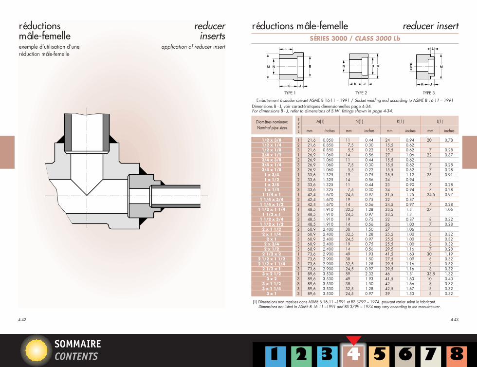
réductionsmâle-femelleexemple d’utilisation d’une réduction mâle-femelle
(1) Dimensions non reprises dans ASME B 16.11 –1991 et BS 3799 – 1974, pouvant varier selon le fabricant.Dimensions not listed in ASME B 16.11 –1991 and BS 3799 – 1974 may vary according to the manufacturer.
SÉRIES 3000 / CLASS 3000 Lb
Dimensions B - J, voir caractéristiques dimensionnelles page 4-34.For dimensions B - J, refer to dimensions of S.W. fittings shown in page 4-34.
Emboîtement à souder suivant ASME B 16-11 – 1991 / Socket welding end according to ASME B 16-11 – 1991
TYPE 1 TYPE 2 TYPE 3
CHAPITRE 4 25/08/1998 16:13 Page 22
Iuliana.Chila
Rectangle
SOMMAIRECONTENTS
4-44 4-45
réductions mâle-femelle reducer insert
Q
B
D
R
J
C
(1) Dimensions non reprises dans ASME B 16.11 –1991 et BS 3799 – 1974, pouvant varier selon le fabricant.Dimensions not listed in ASME B 16.11 –1991 and BS 3799 – 1974 may vary according to the manufacturer.
Dimensions B - C - D - J, voir caractéristiques dimensionnelles page 4-34.For dimensions B - C - D - J, refer to dimensions of S.W. fittings shown in page 4-34.
Diamètre nominalNominal pipe size
mm
3000 6000
inches mm inches mm inchesmm
Q(1) R(1) Q(1) R(1)
inches
1/4 42,5 1.67 36,0 1.42 54,0 2.13 46,0 1.81
3/8 47,5 1.87 41,0 1.62 57,0 2.25 51,0 2.00
1/2 52,0 2.05 46,0 1.81 69,0 2.72 60,0 2.36
3/4 57,0 2.25 56,0 2.20 72,0 2.84 72,0 2.84
1 63,0 2.48 65,0 2.56 80,0 3.15 80,0 3.15
1 1/4 68,0 2.76 80,0 3.07 89,0 3.50 94,0 3.70
1 1/2 78,0 3.07 88,0 3.39 108,0 4.25 100,0 3.94
2 91,0 3.50 105,0 4.06 114,0 4.49 122,0 4.80
2 1/2 120,0 4.49 122,0 4.80
3 120,0 5.12 144,0 5.67
4 148,0 5.91 200,0 7.09
(1) Dimensions non reprises dans ASME B 16.11 –1991 et BS 3799 – 1974, pouvant varier selon le fabricant.Dimensions not listed in ASME B 16.11 –1991 and BS 3799 – 1974 may vary according to the manufacturer.
– – – –
– – – –
– – – –
Emboîtement à souder suivant ASME B 16-11 – 1991Socket welding end and according to ASME B 16-11 – 1991
M BN
K
L
J
MBN
K J
MN
K J
L
Dimensions B - J, voir caractéristiques dimensionnelles page 4-34.For dimensions B - J, refer to dimensions of S.W. fittings shown in page 4-34.
Emboîtement à souder suivant ASME B 16-11 – 1991 / Socket welding end according to ASME B 16-11 – 1991
TYPE 1 TYPE 2 TYPE 3
CHAPITRE 4 25/08/1998 16:13 Page 23
SOMMAIRECONTENTS
4-474-46
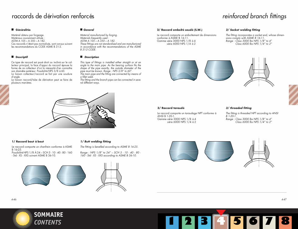
raccords de dérivation renforcés reinforced branch fittings
m Généralités
Matériel obtenu par forgeage.Matériaux couramment utilisés :ASTM A 105 – A 350 – A 182.Ces raccords n’étant pas normalisés, sont conçus suivantles recommandations du CODE ASME B 31-3.
m Descriptif
Ce type de raccord est posé droit ou incliné sur le col-lecteur principal, la face d’appui du raccord épouse laforme de ce collecteur d’où la nécessité d’en connaîtreson diamètre extérieur. Possibilité NPS 3/8 à 60.La liaison collecteur/raccord se fait par une soudured’angle.La liaison raccord/tube de dérivation peut se faire deplusieurs manières.
m General
Material manufactured by forging.Materials frequently used :ASTM A 105 – A 350 – A 182.These fittings are not standardised and are manufacturedin accordance with the recommendations of the ASMEB 31-3 CODE.
m Description
This type of fittings is installed either straight or at anangle to the main pipe. As the bearing surface fits theshape of the pipe exactly, the outside diameter of thepipe must be known. Range : NPS 3/8” to 60”.The main pipe and the fitting are connected by means ofa fillet weld.The fitting and the branch pipe can be connected in seve-ral different ways.
1/ Raccord bout à bout
Le raccord comporte un chanfrein conforme à ASMEB 16-25.Possibilité NPS 1/8 À 24 – SCH 5 - 10 - 40 - 80 - 160- Std - XS - XXS suivant ASME B 36-10.
1/ Butt welding fitting
The fitting is bevelled according to ASME B 16-25.
Range : NPS 1/8” to 24” – SCH 5 - 10 - 40 - 80 -160 - Std - XS - XXS according to ASME B 36-10.
2/ Raccord emboîté soudé (S.W.)
Le raccord comporte un emboîtement de dimensionsconforme à ASME B 16-11.Gamme série 3000 NPS 1/8 à 4
série 6000 NPS 1/4 à 2
2/ Socket welding fitting
The fitting incorporates a socket end, whose dimen-sions comply with ASME B 16-11.Range : Class 3000 lbs NPS 1/8” to 4”
Class 6000 lbs NPS 1/4” to 2”
3/ Raccord taraudé
Le raccord comporte un taraudage NPT conforme àANSI B 1-20-1.Gamme série 3000 NPS 1/8 à 4
série 6000 NPS 1/4 à 2
3/ threaded fitting
The fitting is threaded NPT according to ANSIB 1-20-1.Range : Class 3000 lbs NPS 1/8” to 4”
Class 6000 lbs NPS 1/4” to 2”
CHAPITRE 4 25/08/1998 16:13 Page 24
SOMMAIRECONTENTS
4-494-48
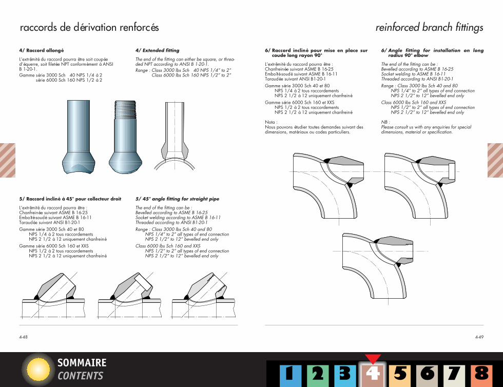
4/ Raccord allongé
L’extrêmité du raccord pourra être soit coupéed’équerre, soit filetée NPT conformément à ANSIB 1-20-1.Gamme série 3000 Sch 40 NPS 1/4 à 2
série 6000 Sch 160 NPS 1/2 à 2
4/ Extended fitting
The end of the fitting can either be square, or threa-ded NPT according to ANSI B 1-20-1.Range : Class 3000 lbs Sch 40 NPS 1/4” to 2”
Class 6000 lbs Sch 160 NPS 1/2” to 2”
5/ Raccord incliné à 45° pour collecteur droit
L’extrêmité du raccord pourra être :Chanfreinée suivant ASME B 16-25Emboîté-soudé suivant ASME B 16-11Taraudée suivant ANSI B1-20-1Gamme série 3000 Sch 40 et 80
NPS 1/4 à 2 tous raccordementsNPS 2 1/2 à 12 uniquement chanfreiné
Gamme série 6000 Sch 160 et XXSNPS 1/2 à 2 tous raccordementsNPS 2 1/2 à 12 uniquement chanfreiné
5/ 45° angle fitting for straight pipe
The end of the fitting can be :Bevelled according to ASME B 16-25Socket welding according to ASME B 16-11Threaded according to ANSI B1-20-1Range : Class 3000 lbs Sch 40 and 80
NPS 1/4” to 2” all types of end connectionNPS 2 1/2” to 12” bevelled end only
Class 6000 lbs Sch 160 and XXS NPS 1/2” to 2” all types of end connectionNPS 2 1/2” to 12” bevelled end only
6/ Raccord incliné pour mise en place surcoude long rayon 90°
L’extrêmité du raccord pourra être :Chanfreinée suivant ASME B 16-25Emboîté-soudé suivant ASME B 16-11Taraudée suivant ANSI B1-20-1Gamme série 3000 Sch 40 et 80
NPS 1/4 à 2 tous raccordementsNPS 2 1/2 à 12 uniquement chanfreiné
Gamme série 6000 Sch 160 et XXSNPS 1/2 à 2 tous raccordementsNPS 2 1/2 à 12 uniquement chanfreiné
Nota :Nous pouvons étudier toutes demandes suivant desdimensions, matériaux ou codes particuliers.
6/ Angle fitting for installation on longradius 90° elbow
The end of the fitting can be :Bevelled according to ASME B 16-25Socket welding to ASME B 16-11Threaded according to ANSI B1-20-1Range : Class 3000 lbs Sch 40 and 80
NPS 1/4” to 2” all types of end connectionNPS 2 1/2” to 12” bevelled end only
Class 6000 lbs Sch 160 and XXS NPS 1/2” to 2” all types of end connectionNPS 2 1/2” to 12” bevelled end only
NB :Please consult us with any enquiries for specialdimensions, material or specification.
raccords de dérivation renforcés reinforced branch fittings
CHAPITRE 4 25/08/1998 16:13 Page 25
SOMMAIRECONTENTS
CHAPITRE 4 25/08/1998 16:14 Page 26
SOMMAIRECONTENTS
4-534-52
pièces spéciales de raccordement / dérivation à rayons perturbés
special forgedbranch fittings
Usinages sur tours et fraiseusesnumériques de pièces forgées à rayons perturbés, en toutesnuances d’aciers, ayant fait l’ob-jet de calculs de résistance et dedimensionnement selon codes de construction internationaux(ASME, CODAP, etc...)
Machining of special forgedbranch fittings, using CNC andmilling machines, in all gradesof steel, in accordance with thedesign requirements of the follo-wing international standards(ASME, CODAP, etc...)