1. Getting Started 1.1 IntroductionThis manual provides operation instructions and information required to operate the Hunter Revolution™ Tire Changer. Read and become familiar with the contents of this manual prior to operating the Hunter Revolution™ Tire Changer.
The owner of the Hunter Revolution™ Tire Changer is solely responsible for arranging technical training. The Hunter Revolution™ Tire Changer is to be operated only by qualified trained technicians. Maintaining records of personnel trained is solely the responsibility of the owner and management.
This manual assumes the technician has already been trained in basic tire changing procedures.
References
This manual assumes that you are already familiar with the basics of tire changing. The first section provides the basic information needed to operate the The Hunter Revolution™ Tire Changer. The following sections contain detailed information about equipment operation and procedures. “Italics” are used to refer to specific parts of this manual that provide additional information or explanation. For example, “1.3 Hunter Revolution™ Tire Changer Components” on page 1. These references should be read for additional information to the instructions being presented.
8 GETTING STARTED
Verify the appropriate electrical supply circuit is the same voltage and amperage ratings as marked on the tire changer before operating.
WARNING: DO NOT ALTER THE ELECTRICAL PLUG. Plugging the electrical plug into an unsuitable supply circuit will damage the equipment and may result in personal injury.
To reduce the risk of fire, do not operate equipment near open containers of flammable liquids (gasoline).
Read and follow all caution and warning labels affixed to your equipment and tools. Misuse of this equipment can cause personal injury and shorten the life of the tire changer.
Keep all instructions permanently with the unit.
Keep all decals, labels, and notices clean and visible.
To prevent accidents and/or damage to the tire changer, use only Hunter Revolution™ Tire Changer recommended accessories.
Use equipment only as described in this manual.
Never stand on the tire changer.
Wear non-slip safety footwear when operating the tire changer.
Keep hair, loose clothing, neckties, jewelry, fingers, and all parts of body away from all moving parts.
ALWAYS WEAR OSHA APPROVED SAFETY GLASSES. Eyeglasses that have only impact resistant lenses are NOT safety glasses.
Do not let cord hang over any edge or contact fan blades or hot objects.
Wear proper back support when lifting or removing tire and or rim from the tire changer.
The red “STOP” button, can be used for emergency stops.
WARNING: Do not hose down, power wash or spray the unit with water.
WARNING: Keep hands and clothing clear of moving parts. Keep hands clear of rollers and clamp when in operation.
WARNING: Do not lean or reach over tire changer when inflating.
1.2 For Your Safety
Hazard Definitions
Watch for these symbols:
CAUTION: Hazards or unsafe practices, which could result in minor personal injury or product or property damage.
WARNING: Hazards or unsafe practices, which could result in severe personal injury or death.
DANGER: Immediate hazards, which will result in severe personal injury or death.
These symbols identify situations that could be detrimental to your safety and/or cause equipment damage.
In addition, notes will appear as:
NOTE: Information pertaining to a specific step, procedure or feature.
IMPORTANT SAFETY INSTRUCTIONS
Read all instructions before operating the The Hunter Revolution™ Tire Changer. Read and follow the instructions and warnings provided in the service, operation and specification documents of the products with which this The Hunter Revolution™ Tire Changer is used (i.e., automobile manufacturers, tire manufacturers etc.).
Do not operate equipment with a damaged cord or equipment that has been dropped or damaged until a Hunter Service Representative has examined it.
Always unplug equipment from electrical outlet when not in use. Never use the cord to pull the plug from the outlet. Grasp plug, twist and pull to disconnect.
If an extension cord is necessary, a cord with a current rating equal to or more than that of the equipment should be used. Cords rated for less current than the equipment may overheat. Care should be taken to arrange the cord so that it will not be tripped over or pulled.
Verify that the electrical supply circuit and the receptacle are properly grounded.
WARNING: To reduce the risk of electrical shock, do not use on wet surfaces or expose to rain.
GETTING STARTED 9
WARNING: DO NOT ALTER THE ELECTRICAL PLUG. Plugging the electrical plug into an unsuitable supply circuit will damage the equipment and may result in personal injury.
Make sure that the electrical supply circuit and the appropriate receptacle is installed with proper grounding.
To prevent the possibility of electrical shock injury or damage to the equipment when servicing the balancer, power must be disconnected by removing the power cord from the electrical power outlet.
In the event of radio interference, the display may flicker - this is normal.
Specific Precautions/Power Source
The Hunter Revolution™ Tire Changer is intended to operate from a power source that will apply 208-230VAC, 1 phase, 24 amp 50 or 60 Hz, power cable includes NEMA 30 amp plug, L6-30P, between the supply conductors of the power cord. The Revolution Tire Changer is also capable of operating on 210-240VAC, 50 Hz at 24A for use in the international market. The power cord supplied utilizes a twist lock connector, NEMA L6-30P.
Figure 1.
This machine must be connected to a 30 amp branch circuit, or as directed by local ordinances. The branch circuit shall be installed near the equipment and shall be easily accessible. Please refer all power source issues to a certified electrician. Refer to “Installation Instructions for Hunter Revolution™ Tire Changer,” Form 6699-T.
Service and maintain the tire changer regularly as outlined in the “Maintenance” section of this document. For further information contact:
Hunter Engineering Company 11250 Hunter Drive Bridgeton, Missouri 63044 United States of America
http://www.hunter.com
(314) 731-3020
WARNING: Do not exceed these pressure limitations: SUPPLY LINE PRESSURE (from compressor) 12 bar (175 PSI)
OPERATING PRESSURE (gauge on regulator) 6.9 bar (100 PSI)
BEAD SEATING PRESSURE (gauge on screen) 2.8 bar (40 PSI)
DANGER: Never mount a tire to a rim that is not the same diameter (e.g., 16 1/2 inch tire mounting on a 16 inch rim.)
DANGER: Activate blast inflation nozzle only when seating beads. Never point the blast inflation nozzle at yourself or others.
CAUTION: Remove any wheel assembly from the tire changer and reset all tools at the end of the work day to prevent hydraulic fluid drain.
Bleed air pressure from the system before disconnecting air supply line or other pneumatic components. Air is stored in a reservoir for operation of the inflation components. Air pressure can be bled from the system by pulling up on the knob located on the top of the regulator, and then turning it counterclockwise.
WARNING: Do not operate the blast inflation nozzle if the tire is not properly clamped.
CAUTION: Hold the blast inflation nozzle firmly. The nozzle has a kick-back and can strike the operator if not held firmly.
CAUTION: Do not operate the tire changer with worn rubber or plastic parts.
Wheels equipped with TPMS systems or special tire and rim designs may require certain procedures. Consult manufacturer’s service instructions.
SAVE THESE INSTRUCTIONS
Electrical
The Hunter Revolution™ Tire Changer is manufactured to operate at a specific voltage and amperage rating.
Make sure that the appropriate electrical supply circuit is of the same voltage and amperage ratings as marked on the tire changer.
Center w/Quick Clamp and Cam Plate / Variable up to 15 rpm CW / CCW
Torque: 1,186 Nm (875 ft-lbs)
Max Tire Diameter: 1,270 mm (50 in.)
Maximum Wheel Width: 381 mm (15 in.)
Rim Diameter Range: 305 mm - 762 mm (12 in. - 30 in.)
HydraulicHydraulic Pressure: 117 bar (1,700 psi)
Hydraulic Flow: 16 lpm (4,1 gpm)
AtmosphericTemperature: 0°C to +50°C (+32°F to +122°F)
Relative Humidity: Up to 95% Non-condensing
Altitude: Up to 1829 m (6000 ft.)
GETTING STARTED 11
1.4 Decal Information and Placement
Left Side View
128-1472-2HUNTER ENGINEERING
COMPANY
contained on128-1419-3
CRUSH WARNING
contained on128-1419-3
ENTANGLEMENTWARNING
contained on128-1419-3
ENTANGLEMENTWARNING
contained on128-1419-3
ENTANGLEMENTWARNING
Figure 2.
12 GETTING STARTED
Right Side View
128-1471-2WHEEL LIFT / GO
contained on128-1419-3
CRUSH WARNING
128-1470-2ROTATION
128-1472-2HUNTER ENGINEERING
COMPANY
Figure 3.
GETTING STARTED 13
Front View
128-1149-2AIR BLAST
INFLATOR WARNING
128-284-2GENERAL
OPERATIONSWARNING
128-285-2AIR PRESSURE
LIMITATIONWARNING
128-287-2LEAN/REACH
OVER TIREWARNING
128-485-2VIEW TRAINING
VIDEO
128-323-2WEAR EYE
PROTECTION
Figure 4.
14 GETTING STARTED
1.5 Equipment Components
WHEEL LIFT / GOPEDAL
ROTATIONPEDAL
WHEEL LIFT / ROTATIONSPINDLE
LOWERBEAD
ROLLER
BEAD BLASTINFLATOR
TOOL CONTROLJOYSTICKS
EMERGENCYSTOP
SWITCH
POWERSWITCH
TOUCH SCREENDISPLAY
UPPERBEAD
ROLLER
MOUNT/DEMOUNTTOOL HEAD
PRESS ARMSHOE
WHEEL CLAMPASSEMBLY
CLAMPCONE
PRESS ARMROLLER
CONSOLEWITH
STORAGE
Figure 5.
GETTING STARTED 15
1.6 Touch Screen Display Components
PROCEDURE WHEEL
STEP “SLIDE-OUT” MENU
NAVIGATION MENUTO OTHER SCREENS
AND FUNCTIONS
RIM DIMENSION ANDINFLATION CONTROL TAB
CONTEXT SPECIFICGRAPHIC
INFORMATION TAB
CONTENT SPECIFICOPERATOR
INFORMATIONREALTIME
ACTIVE DISPLAY
GREEN DOT INDICATESCURRENT SELECTION
Figure 6.
16 GETTING STARTED
After the Hunter Revolution™ Tire Changer is powered on, it will perform a self-check and load screen objects. The main interface screen will appear indicating the unit is ready for use.
Figure 8.
Equipment Installation and Service
Only a Hunter Factory-Authorized Representative should perform installation.
This equipment contains no operator serviceable parts. All repairs must be referred to a qualified Hunter Service Representative.
Explanation of Symbols
These symbols may appear on the equipment.
Alternating current.
Earth ground terminal.
Protective conductor terminal.
l ON (supply) condition.
OFF (supply) condition.
Risk of electrical shock.
Stand-by switch.
Not intended for connection to public telecommunications network.
1.7 Equipment Power and Specifications
Turning Power ON/OFF
Push Button Power Switch
The Hunter Revolution™ Tire Changer is equipped with a push button power switch located on the right side of the console, above the emergency stop switch. Use this switch for normal shut down and restarting procedures.
To prevent loss of data, always use the push button switch on the side of the console to power the tire changer on and off.
Emergency Stop Switch
The Hunter Revolution™ Tire Changer is equipped with an emergency stop switch located on the right side of the console, below the push button power switch. Push this switch for an immediate termination of all hydraulic functions, e.g., spindle rotation, tool movement, etc. Pull the switch back out to resume hydraulic functions. (Figure 7.)
POWERSWITCH
EMERGENCYSTOP SWITCH
WHEEL LIFTDOWN
WHEEL LIFTUP / GO
ROTATION—
DOWN FORCLOCKWISE
—UP FOR
COUNTERCLOCKWISE
PRESS ARMROLLER
PRESS ARMSHOE
Figure 7.
NOTE: Use of the emergency stop switch will NOT shut down the computer and LCD functions.
GETTING STARTED 17
1.8 Operating the Tire Changer
Changing Display Language
The display language can be changed by the operator. A choice of two languages may be selected and toggled between. The following example will show how to display English and French Canadian.
Figure 9.
To change the display language:
From the main screen, touch “Utility”.
Touch “Set Up”.
Select “Display Language”, then touch “Set Up Selected Item”.
Figure 10.
Select the primary and alternate languages to be displayed.
Figure 11.
Touch “OK”.
Touch “Store Set Up”.
The primary and alternate languages will now be displayed. To change from primary to alternate, touch the desired icon.
Figure 12.
Figure 13.
Touch Screen Display
A procedure wheel is located on the left side of the screen. Steps can be skipped and accessed by rolling the wheel up or down and touching the desired selection. In most cases, touching a selection initiates a “slide-out” menu providing additional functions.
18 GETTING STARTED
Buttons along the right side allow navigation to other screens and functions.
Figure 18.
Wheel Lift / GO Pedal
CAUTION: Keep hands clear of wheel, tire and rollers during operation.
NOTE: During normal operation, the GO pedal is pressed the majority of the time to complete procedures.
Releasing the GO pedal will pause the current procedure. Slide-out menus on the touch screen procedure wheel may change, allowing for other options.
In most cases, pressing back down on the GO pedal will continue the previously paused procedure.
To raise the wheel lift, press and hold down the right side of the pedal.
To lower the wheel lift, press and hold down left side of the pedal.
Once the spindle is vertical, the right side of the pedal becomes the GO pedal.
NOTE: If the wheel lift is less than vertical, the “GO” function is disabled until the spindle is vertical.
If the wheel lift is less than vertical, the “GO” function is disabled until the spindle is vertical.
Figure 14.
When the operator needs more info in a non-error condition, prompting text will appear in the lower portion of the screen.
Figure 15.
The bottom left interface tab provides context specific graphic information for the current task.
Figure 16.
The bottom right interface tab shows rim dimensions and in later steps, inflation controls.
Figure 17.
GETTING STARTED 19
To rotate the spindle counter clockwise, lift and hold the rotation pedal. Release when assembly is rotated to desired position.
CAUTION: Keep hands clear of wheel, tire and rollers during rotation.
POWERSWITCH
EMERGENCYSTOP SWITCH
WHEEL LIFTDOWN
WHEEL LIFTUP / GO
ROTATION—
DOWN FORCLOCKWISE
—UP FOR
COUNTERCLOCKWISE
PRESS ARMROLLER
PRESS ARMSHOE
Figure 20.
Press Arms
The bead pushers assist with tire mounting. The pushers moves in tandem with the mount / demount tool head.
POWERSWITCH
EMERGENCYSTOP SWITCH
WHEEL LIFTDOWN
WHEEL LIFTUP / GO
ROTATION—
DOWN FORCLOCKWISE
—UP FOR
COUNTERCLOCKWISE
PRESS ARMROLLER
PRESS ARMSHOE
Figure 21.
To perform automated tasks, press and release the right side of the pedal. This is referred to as the “GO” pedal.
POWERSWITCH
EMERGENCYSTOP SWITCH
WHEEL LIFTDOWN
WHEEL LIFTUP / GO
ROTATION—
DOWN FORCLOCKWISE
—UP FOR
COUNTERCLOCKWISE
PRESS ARMROLLER
PRESS ARMSHOE
Figure 19.
Rotation Pedal
To rotate the spindle clockwise, press and hold down the rotation pedal. Release when assembly is rotated to desired position.
20 GETTING STARTED
1.9 Identify SoftwareTo identify the software:
From the main screen, touch “Utility”.
Touch “Identify Software” to view the version information of the tire changer.
Figure 23.
Touch “Show Authorization” to view the key information of the tire changer.
Figure 24.
Touch “Show Usage Stats” to view usage information of the tire changer.
Touch “Exit” to return to the main screen.
Tool Control Joysticks
To move the tools for operations such as setting rim diameter, manual controls, etc., use the joystick that corresponds to the appropriate tool.
CAUTION: Keep hands clear of wheel, tire, rollers and other tools during operation.
Figure 22.
BASIC PROCEDURES 21
2.1 Using the Wheel LiftNOTE: Remove wheel clamp before beginning this procedure.
To lower the wheel lift, press and hold down the left side of the pedal. Release the pedal when the spindle is at the appropriate height for the wheel to be serviced.
Figure 25.
Position wheel in front of spindle and tilt it so the center hole aligns with the top of the spindle.
Figure 26.
Raise or lower the spindle as needed to align the center hole.
Figure 27.
With top of the spindle in the rim center hole, press and hold down the right side of the pedal to raise the wheel assembly. Release the pedal when the wheel assembly reaches operating position.
2. Basic Procedures
22 BASIC PROCEDURES
2.2 Clamping the Wheel
Use of the Clamping Cone
Standard Size Center Hole
For standard size center holes, use the clamping cone with the high taper side down.
ANTI-ROTATIONPIN
STANDARD SIZECENTER HOLE
HIGH TAPERSIDE OF CONE
DOWN
LARGE SIZECENTER HOLE
LOW TAPERSIDE OF CONE
DOWN
SMALL SIZECENTER HOLE
CONEREMOVED
GREEN BANDVISIBLE
DEPRESSBUTTON
SLIDE DOWNUNTIL CONTACT
WITH RIM ISMADE
Figure 30.
Large Center Hole
For large size center holes, use the clamping cone with the low taper side down. Remove the cone and flip it over on the clamping shaft.
ANTI-ROTATIONPIN
STANDARD SIZECENTER HOLE
HIGH TAPERSIDE OF CONE
DOWN
LARGE SIZECENTER HOLE
LOW TAPERSIDE OF CONE
DOWN
SMALL SIZECENTER HOLE
CONEREMOVED
GREEN BANDVISIBLE
DEPRESSBUTTON
SLIDE DOWNUNTIL CONTACT
WITH RIM ISMADE
Figure 31.
Small Center Hole
For small center holes, remove the clamping cone entirely.
ANTI-ROTATIONPIN
STANDARD SIZECENTER HOLE
HIGH TAPERSIDE OF CONE
DOWN
LARGE SIZECENTER HOLE
LOW TAPERSIDE OF CONE
DOWN
SMALL SIZECENTER HOLE
CONEREMOVED
GREEN BANDVISIBLE
DEPRESSBUTTON
SLIDE DOWNUNTIL CONTACT
WITH RIM ISMADE
Figure 32.
Figure 28.
Rotate the wheel assembly until the anti-rotation pin enters a lug hole in the rim. The anti-rotation pin will spring up into place.
ANTI-ROTATIONPIN
STANDARD SIZECENTER HOLE
HIGH TAPERSIDE OF CONE
DOWN
LARGE SIZECENTER HOLE
LOW TAPERSIDE OF CONE
DOWN
SMALL SIZECENTER HOLE
CONEREMOVED
GREEN BANDVISIBLE
DEPRESSBUTTON
SLIDE DOWNUNTIL CONTACT
WITH RIM ISMADE
Figure 29.
BASIC PROCEDURES 23
CAUTION: Keep hands clear of wheel and clamp when performing the next step of the procedure.
Press and release the right “GO” side of the pedal to fully seat the clamp and secure the wheel.
Figure 36.
Clamping Procedure
Fully depress the button on the top of the clamp assembly.
Figure 33.
Insert the clamp through the rim center hole and into the top of the spindle.
CAUTION: When the clamp is properly inserted, the button on the top of the clamp will spring up, showing the green band. If the green band is not visible, re-seat the clamp. DO NOT proceed unless the green band is visible.
ANTI-ROTATIONPIN
STANDARD SIZECENTER HOLE
HIGH TAPERSIDE OF CONE
DOWN
LARGE SIZECENTER HOLE
LOW TAPERSIDE OF CONE
DOWN
SMALL SIZECENTER HOLE
CONEREMOVED
GREEN BANDVISIBLE
DEPRESSBUTTON
SLIDE DOWNUNTIL CONTACT
WITH RIM ISMADE
Figure 34.
If the cone or base of the clamp is not contacting the rim surface, depress the button on the side of the clamp and slide the clamp down until contact is made. Then, release the button.
ANTI-ROTATIONPIN
STANDARD SIZECENTER HOLE
HIGH TAPERSIDE OF CONE
DOWN
LARGE SIZECENTER HOLE
LOW TAPERSIDE OF CONE
DOWN
SMALL SIZECENTER HOLE
CONEREMOVED
GREEN BANDVISIBLE
DEPRESSBUTTON
SLIDE DOWNUNTIL CONTACT
WITH RIM ISMADE
Figure 35.
24 BASIC PROCEDURES
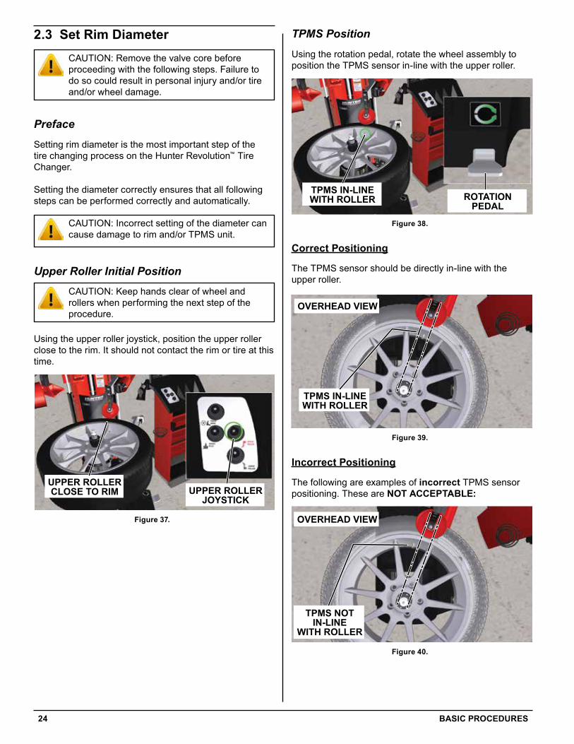
TPMS Position
Using the rotation pedal, rotate the wheel assembly to position the TPMS sensor in-line with the upper roller.
UPPER ROLLERJOYSTICK
UPPER ROLLERCLOSE TO RIM
ROTATIONPEDAL
TPMS IN-LINEWITH ROLLER
TOP OF RIM
TOP EDGEOF ROLLERSMALL GAP
TOP EDGEOF ROLLERBELOW RIM
EDGE
TOP EDGEOF ROLLERABOVE RIM
EDGE
EDGE OFROLLER TOO
FAR FROM RIMEDGE
EDGE OFROLLER
OVERLAPPINGRIM EDGE
TOP BEADFULLY
BROKEN
Figure 38.
Correct Positioning
The TPMS sensor should be directly in-line with the upper roller.
TOP BEAD HAS FAILED TO MOUNT
ROTATE BEAD PUSHERS
BEAD PUSHERSLOWERED PUSHING
AGAINST TIRE
LIFT TIRE AND PRESS NOZZLE AGAINST RIM
ROTATE WHEEL ASSEMBLY 180°USE RUBBER PAD TO PROTECT WHEEL SURFACE
OVERHEAD VIEW
TPMS IN-LINEWITH ROLLER
OVERHEAD VIEW
TPMS NOTIN-LINE
WITH ROLLER
OVERHEAD VIEW
TPMS NOTIN-LINE
WITH ROLLER
Figure 39.
Incorrect Positioning
The following are examples of incorrect TPMS sensor positioning. These are NOT ACCEPTABLE:
TOP BEAD HAS FAILED TO MOUNT
ROTATE BEAD PUSHERS
BEAD PUSHERSLOWERED PUSHING
AGAINST TIRE
LIFT TIRE AND PRESS NOZZLE AGAINST RIM
ROTATE WHEEL ASSEMBLY 180°USE RUBBER PAD TO PROTECT WHEEL SURFACE
OVERHEAD VIEW
TPMS IN-LINEWITH ROLLER
OVERHEAD VIEW
TPMS NOTIN-LINE
WITH ROLLER
OVERHEAD VIEW
TPMS NOTIN-LINE
WITH ROLLER
Figure 40.
2.3 Set Rim DiameterCAUTION: Remove the valve core before proceeding with the following steps. Failure to do so could result in personal injury and/or tire and/or wheel damage.
Preface
Setting rim diameter is the most important step of the tire changing process on the Hunter Revolution™ Tire Changer.
Setting the diameter correctly ensures that all following steps can be performed correctly and automatically.
CAUTION: Incorrect setting of the diameter can cause damage to rim and/or TPMS unit.
Upper Roller Initial Position
CAUTION: Keep hands clear of wheel and rollers when performing the next step of the procedure.
Using the upper roller joystick, position the upper roller close to the rim. It should not contact the rim or tire at this time.
UPPER ROLLERJOYSTICK
UPPER ROLLERCLOSE TO RIM
ROTATIONPEDAL
TPMS IN-LINEWITH ROLLER
TOP OF RIM
TOP EDGEOF ROLLERSMALL GAP
TOP EDGEOF ROLLERBELOW RIM
EDGE
TOP EDGEOF ROLLERABOVE RIM
EDGE
EDGE OFROLLER TOO
FAR FROM RIMEDGE
EDGE OFROLLER
OVERLAPPINGRIM EDGE
TOP BEADFULLY
BROKEN
Figure 37.
BASIC PROCEDURES 25
UPPER ROLLERJOYSTICK
UPPER ROLLERCLOSE TO RIM
ROTATIONPEDAL
TPMS IN-LINEWITH ROLLER
TOP OF RIM
TOP EDGEOF ROLLERSMALL GAP
TOP EDGEOF ROLLERBELOW RIM
EDGE
TOP EDGEOF ROLLERABOVE RIM
EDGE
EDGE OFROLLER TOO
FAR FROM RIMEDGE
EDGE OFROLLER
OVERLAPPINGRIM EDGE
TOP BEADFULLY
BROKEN
Figure 44.
UPPER ROLLERJOYSTICK
UPPER ROLLERCLOSE TO RIM
ROTATIONPEDAL
TPMS IN-LINEWITH ROLLER
TOP OF RIM
TOP EDGEOF ROLLERSMALL GAP
TOP EDGEOF ROLLERBELOW RIM
EDGE
TOP EDGEOF ROLLERABOVE RIM
EDGE
EDGE OFROLLER TOO
FAR FROM RIMEDGE
EDGE OFROLLER
OVERLAPPINGRIM EDGE
TOP BEADFULLY
BROKEN
Figure 45.
UPPER ROLLERJOYSTICK
UPPER ROLLERCLOSE TO RIM
ROTATIONPEDAL
TPMS IN-LINEWITH ROLLER
TOP OF RIM
TOP EDGEOF ROLLERSMALL GAP
TOP EDGEOF ROLLERBELOW RIM
EDGE
TOP EDGEOF ROLLERABOVE RIM
EDGE
EDGE OFROLLER TOO
FAR FROM RIMEDGE
EDGE OFROLLER
OVERLAPPINGRIM EDGE
TOP BEADFULLY
BROKEN
Figure 46.
Complete the Process
Once the upper roller is correctly positioned, press and release the right “GO” side of the pedal to set the rim diameter.
Figure 47.
TOP BEAD HAS FAILED TO MOUNT
ROTATE BEAD PUSHERS
BEAD PUSHERSLOWERED PUSHING
AGAINST TIRE
LIFT TIRE AND PRESS NOZZLE AGAINST RIM
ROTATE WHEEL ASSEMBLY 180°USE RUBBER PAD TO PROTECT WHEEL SURFACE
OVERHEAD VIEW
TPMS IN-LINEWITH ROLLER
OVERHEAD VIEW
TPMS NOTIN-LINE
WITH ROLLER
OVERHEAD VIEW
TPMS NOTIN-LINE
WITH ROLLER
Figure 41.
Upper Roller Set Diameter Position
Correct Positioning
Using the upper roller joystick, position the upper roller so its top edge is nearly flush with the top edge of the rim. It may be necessary to slightly depress the sidewall of the tire with the roller. A small gap between the edge of the roller and the edge of the rim is ok.
UPPER ROLLERJOYSTICK
UPPER ROLLERCLOSE TO RIM
ROTATIONPEDAL
TPMS IN-LINEWITH ROLLER
TOP OF RIM
TOP EDGEOF ROLLERSMALL GAP
TOP EDGEOF ROLLERBELOW RIM
EDGE
TOP EDGEOF ROLLERABOVE RIM
EDGE
EDGE OFROLLER TOO
FAR FROM RIMEDGE
EDGE OFROLLER
OVERLAPPINGRIM EDGE
TOP BEADFULLY
BROKEN
Figure 42.
Incorrect Positioning
The following are examples of incorrect upper roller positioning. These are NOT ACCEPTABLE:
UPPER ROLLERJOYSTICK
UPPER ROLLERCLOSE TO RIM
ROTATIONPEDAL
TPMS IN-LINEWITH ROLLER
TOP OF RIM
TOP EDGEOF ROLLERSMALL GAP
TOP EDGEOF ROLLERBELOW RIM
EDGE
TOP EDGEOF ROLLERABOVE RIM
EDGE
EDGE OFROLLER TOO
FAR FROM RIMEDGE
EDGE OFROLLER
OVERLAPPINGRIM EDGE
TOP BEADFULLY
BROKEN
Figure 43.
26 BASIC PROCEDURES
2.4 Select Mode
Preface
Once rim diameter has been set, the next typical procedure is to demount the tire from the rim. However, certain circumstances may exist that require non-typical functions. For example, if the tire has already been demounted, the operator can select to mount both beads or mount the top bead only.
Demount
Demount is the default procedure after setting the rim diameter. To proceed demounting, simply press and release the right “GO” side of the pedal. (Figure 49.)
Figure 49.
The Hunter Revolution™ Tire Changer will proceed to the next procedure. The procedure wheel will automatically advance.
Mount Both Beads
If the tire has already been demounted, the operator can select to mount both beads by touching the “Mount Both Beads” slide-out button on the procedure wheel.
Figure 50.
The Hunter Revolution™ Tire Changer will proceed to the next procedure. The procedure wheel will automatically advance.
Repeating Wheels in Sets
NOTE: The next procedure in the procedure wheel is “Select Mode”. However, when repeating wheels in sets, or changing to a new sized assembly, new slide-out menu options are available in the “Set Diameter” step.
In most cases the operator will be servicing wheels in sets. When the next assembly is loaded onto the tire changer and clamped, the “Set Diameter” button will display a different slide-out menu. The items listed are “Same as Last” and “Save this Location”.
Figure 48.
If the wheel assembly is from the same set, (same diameter and width) “Same as Last” will be highlighted. Correctly position the TPMS and proceed by pressing the right “GO” side of the pedal.
If the wheel assembly is new, (new size, etc.) repeat the upper roller positioning procedure. The slide-out buttons will switch position and “Save this Location” will now be selected. Correctly position the TPMS and proceed by pressing the right “GO” side of the pedal.
BASIC PROCEDURES 27
2.5 Breaking BeadsCAUTION: Keep hands clear of wheel and rollers when performing the next step of the procedure.
CAUTION: Remove the valve core before proceeding with the following steps. Failure to do so could result in personal injury and/or tire and/or wheel damage.
Normal Bead Breaking Procedure
Press and hold the right “GO” side of the pedal to break the beads. The upper and lower rollers will begin to break the beads as the wheel assembly rotates.
Look at the beads to confirm they are fully broken from the rim.
UPPER ROLLERJOYSTICK
UPPER ROLLERCLOSE TO RIM
ROTATIONPEDAL
TPMS IN-LINEWITH ROLLER
TOP OF RIM
TOP EDGEOF ROLLERSMALL GAP
TOP EDGEOF ROLLERBELOW RIM
EDGE
TOP EDGEOF ROLLERABOVE RIM
EDGE
EDGE OFROLLER TOO
FAR FROM RIMEDGE
EDGE OFROLLER
OVERLAPPINGRIM EDGE
TOP BEADFULLY
BROKEN
Figure 52.
BOTTOM BEADFULLY
BROKEN
MOUNT/DEMOUNT TOOL HEAD AT RIM EDGE
BEAD PULLED UP OVER THE RIM EDGE
BEADHOOK
TOP BEAD FULLY DEMOUNTED
BEAD HOOK NOT INSERTED
LUBRICATE THE TOP BEAD
LUBRICATE THE BEAD HOOK
BEAD HOOK FAILED TO PULLBEAD OVER RIM EDGE
Figure 53.
Mount Top Bead Only
If the tire has already been demounted and the bottom bead has been mounted, the operator can select to mount the top bead by touching the “Mount Top Bead Only” slide-out button on the procedure wheel.
Figure 51.
The Hunter Revolution™ Tire Changer will proceed to the next procedure. The procedure wheel will automatically advance.
28 BASIC PROCEDURES
2.6 Top Bead DemountCAUTION: Keep hands clear of wheel, mount/demount tool head, bead pushers and rollers when performing the next step of the procedure.
Normal Top Bead Demount
Press and hold the right “GO” side of the pedal to demount the top bead. The mount/demount tool head will lower to the rim edge as the wheel assembly rotates.
BOTTOM BEADFULLY
BROKEN
MOUNT/DEMOUNT TOOL HEAD AT RIM EDGE
BEAD PULLED UP OVER THE RIM EDGE
BEADHOOK
TOP BEAD FULLY DEMOUNTED
BEAD HOOK NOT INSERTED
LUBRICATE THE TOP BEAD
LUBRICATE THE BEAD HOOK
BEAD HOOK FAILED TO PULLBEAD OVER RIM EDGE
Figure 56.
The bead hook will lower into the gap between the rim edge and the tire. Wheel assembly rotation will stop and the hook will pull the bead up over the rim edge.
BOTTOM BEADFULLY
BROKEN
MOUNT/DEMOUNT TOOL HEAD AT RIM EDGE
BEAD PULLED UP OVER THE RIM EDGE
BEADHOOK
TOP BEAD FULLY DEMOUNTED
BEAD HOOK NOT INSERTED
LUBRICATE THE TOP BEAD
LUBRICATE THE BEAD HOOK
BEAD HOOK FAILED TO PULLBEAD OVER RIM EDGE
Figure 57.
The wheel assembly will then rotate clockwise as the top bead is fully demounted.
BOTTOM BEADFULLY
BROKEN
MOUNT/DEMOUNT TOOL HEAD AT RIM EDGE
BEAD PULLED UP OVER THE RIM EDGE
BEADHOOK
TOP BEAD FULLY DEMOUNTED
BEAD HOOK NOT INSERTED
LUBRICATE THE TOP BEAD
LUBRICATE THE BEAD HOOK
BEAD HOOK FAILED TO PULLBEAD OVER RIM EDGE
Figure 58.
Retry Bead Break
If the beads will not break from the rim, release the right “GO” side of the pedal. From the procedure wheel slide-out menu, touch “Retry Bead Break”. Press and hold the right “GO” side of the pedal to retry the procedure.
Figure 54.
Skip Bead Break
If the beads have already been broken from the rim, the operator can select to bypass the “Breaking Beads” step.
Release the right “GO” side of the pedal. From the procedure wheel slide-out menu, touch “Skip Bead Break”. Press and hold the right “GO” side of the pedal.
Figure 55.
The Hunter Revolution™ Tire Changer will proceed to the next procedure. The procedure wheel will automatically advance.
BASIC PROCEDURES 29
From the procedure wheel slide-out menu, touch “Retry - Hook Not Inserted”. Press and hold the right “GO” side of the pedal to retry the procedure.
Figure 62.
Bead Hook Fails to Pull Over Top Bead
On some tires, the bead hook may fail to pull the top bead over the rim edge.
BOTTOM BEADFULLY
BROKEN
MOUNT/DEMOUNT TOOL HEAD AT RIM EDGE
BEAD PULLED UP OVER THE RIM EDGE
BEADHOOK
TOP BEAD FULLY DEMOUNTED
BEAD HOOK NOT INSERTED
LUBRICATE THE TOP BEAD
LUBRICATE THE BEAD HOOK
BEAD HOOK FAILED TO PULLBEAD OVER RIM EDGE
Figure 63.
If this happens, release the right “GO” side of the pedal.
From the procedure wheel slide-out menu, touch “Retry - Use Pusher to Assist”.
Figure 64.
Difficult Tires
Bead Hook Fails to Insert
On some tires, the bead hook may fail to properly insert into the gap between the rim edge and the tire.
BOTTOM BEADFULLY
BROKEN
MOUNT/DEMOUNT TOOL HEAD AT RIM EDGE
BEAD PULLED UP OVER THE RIM EDGE
BEADHOOK
TOP BEAD FULLY DEMOUNTED
BEAD HOOK NOT INSERTED
LUBRICATE THE TOP BEAD
LUBRICATE THE BEAD HOOK
BEAD HOOK FAILED TO PULLBEAD OVER RIM EDGE
Figure 59.
If this happens, release the right “GO” side of the pedal.
Lubricate the top bead and the bead hook.
BOTTOM BEADFULLY
BROKEN
MOUNT/DEMOUNT TOOL HEAD AT RIM EDGE
BEAD PULLED UP OVER THE RIM EDGE
BEADHOOK
TOP BEAD FULLY DEMOUNTED
BEAD HOOK NOT INSERTED
LUBRICATE THE TOP BEAD
LUBRICATE THE BEAD HOOK
BEAD HOOK FAILED TO PULLBEAD OVER RIM EDGE
Figure 60.
BOTTOM BEADFULLY
BROKEN
MOUNT/DEMOUNT TOOL HEAD AT RIM EDGE
BEAD PULLED UP OVER THE RIM EDGE
BEADHOOK
TOP BEAD FULLY DEMOUNTED
BEAD HOOK NOT INSERTED
LUBRICATE THE TOP BEAD
LUBRICATE THE BEAD HOOK
BEAD HOOK FAILED TO PULLBEAD OVER RIM EDGE
Figure 61.
30 BASIC PROCEDURES
BOTTOM BEADFULLY
BROKEN
MOUNT/DEMOUNT TOOL HEAD AT RIM EDGE
BEAD PULLED UP OVER THE RIM EDGE
BEADHOOK
TOP BEAD FULLY DEMOUNTED
BEAD HOOK NOT INSERTED
LUBRICATE THE TOP BEAD
LUBRICATE THE BEAD HOOK
BEAD HOOK FAILED TO PULLBEAD OVER RIM EDGE
Figure 68.
Rotate the bead pushers so they are opposite of the mount/demount tool head.
ROTATE THE BEAD PUSHERS SO THEY AREOPPOSITE OF THE MOUNT/DEMOUNT TOOL HEAD
ROTATE THE BEAD PUSHERS SO THEY AREOPPOSITE OF THE MOUNT/DEMOUNT TOOL HEAD
BEAD PUSHERS LOWEREDPUSHING AGAINST TIRE
MOUNT/DEMOUNT TOOLHEAD WITH HOOK RAISING TIRE
MOUNT/DEMOUNT TOOLHEAD WITH HOOK RAISING TIRE
LOWERROLLER
BOTTOM BEAD IS NOT IN THE RIMDROP CENTER
LIFT THE BOTTOM BEAD INTO THE RIMDROP CENTER
BOTTOM BEAD PINCHEDBETWEEN ROLLER AND RIM
Figure 65.
ROTATE THE BEAD PUSHERS SO THEY AREOPPOSITE OF THE MOUNT/DEMOUNT TOOL HEAD
ROTATE THE BEAD PUSHERS SO THEY AREOPPOSITE OF THE MOUNT/DEMOUNT TOOL HEAD
BEAD PUSHERS LOWEREDPUSHING AGAINST TIRE
MOUNT/DEMOUNT TOOLHEAD WITH HOOK RAISING TIRE
MOUNT/DEMOUNT TOOLHEAD WITH HOOK RAISING TIRE
LOWERROLLER
BOTTOM BEAD IS NOT IN THE RIMDROP CENTER
LIFT THE BOTTOM BEAD INTO THE RIMDROP CENTER
BOTTOM BEAD PINCHEDBETWEEN ROLLER AND RIM
Figure 66.
Press and hold the right “GO” side of the pedal. The bead pushers will lower and push against the tire.
ROTATE THE BEAD PUSHERS SO THEY AREOPPOSITE OF THE MOUNT/DEMOUNT TOOL HEAD
ROTATE THE BEAD PUSHERS SO THEY AREOPPOSITE OF THE MOUNT/DEMOUNT TOOL HEAD
BEAD PUSHERS LOWEREDPUSHING AGAINST TIRE
MOUNT/DEMOUNT TOOLHEAD WITH HOOK RAISING TIRE
MOUNT/DEMOUNT TOOLHEAD WITH HOOK RAISING TIRE
LOWERROLLER
BOTTOM BEAD IS NOT IN THE RIMDROP CENTER
LIFT THE BOTTOM BEAD INTO THE RIMDROP CENTER
BOTTOM BEAD PINCHEDBETWEEN ROLLER AND RIM
Figure 67.
CAUTION: Pushers will automatically rotate. Stay clear of assembly.
The wheel assembly with pushers will then rotate clockwise as the top bead is fully demounted.
BASIC PROCEDURES 31
Difficult Tires
Bottom Bead Not in Rim Drop Center
For a successful bottom bead demount, the operator must ensure the bottom bead is positioned in the rim drop center.
ROTATE THE BEAD PUSHERS SO THEY AREOPPOSITE OF THE MOUNT/DEMOUNT TOOL HEAD
ROTATE THE BEAD PUSHERS SO THEY AREOPPOSITE OF THE MOUNT/DEMOUNT TOOL HEAD
BEAD PUSHERS LOWEREDPUSHING AGAINST TIRE
MOUNT/DEMOUNT TOOLHEAD WITH HOOK RAISING TIRE
MOUNT/DEMOUNT TOOLHEAD WITH HOOK RAISING TIRE
LOWERROLLER
BOTTOM BEAD IS NOT IN THE RIMDROP CENTER
LIFT THE BOTTOM BEAD INTO THE RIMDROP CENTER
BOTTOM BEAD PINCHEDBETWEEN ROLLER AND RIM
Figure 71.
If the bottom bead is not in the rim drop center, release the right “GO” side of the pedal.
Lift the bottom bead into the rim drop center.
CAUTION: Use caution while lifting bottom bead into rim drop center.
ROTATE THE BEAD PUSHERS SO THEY AREOPPOSITE OF THE MOUNT/DEMOUNT TOOL HEAD
ROTATE THE BEAD PUSHERS SO THEY AREOPPOSITE OF THE MOUNT/DEMOUNT TOOL HEAD
BEAD PUSHERS LOWEREDPUSHING AGAINST TIRE
MOUNT/DEMOUNT TOOLHEAD WITH HOOK RAISING TIRE
MOUNT/DEMOUNT TOOLHEAD WITH HOOK RAISING TIRE
LOWERROLLER
BOTTOM BEAD IS NOT IN THE RIMDROP CENTER
LIFT THE BOTTOM BEAD INTO THE RIMDROP CENTER
BOTTOM BEAD PINCHEDBETWEEN ROLLER AND RIM
Figure 72.
From the procedure wheel slide-out menu, touch “Retry - Not in Drop Center”.
Figure 73.
2.7 Bottom Bead DemountCAUTION: Keep hands clear of wheel, mount/demount tool head, bead pushers and rollers when performing the next step of the procedure.
Normal Bottom Bead Demount
Press and hold the right “GO” side of the pedal to demount the bottom bead. The mount/demount tool with head with bead hook will raise the tire as the wheel assembly rotates.
ROTATE THE BEAD PUSHERS SO THEY AREOPPOSITE OF THE MOUNT/DEMOUNT TOOL HEAD
ROTATE THE BEAD PUSHERS SO THEY AREOPPOSITE OF THE MOUNT/DEMOUNT TOOL HEAD
BEAD PUSHERS LOWEREDPUSHING AGAINST TIRE
MOUNT/DEMOUNT TOOLHEAD WITH HOOK RAISING TIRE
MOUNT/DEMOUNT TOOLHEAD WITH HOOK RAISING TIRE
LOWERROLLER
BOTTOM BEAD IS NOT IN THE RIMDROP CENTER
LIFT THE BOTTOM BEAD INTO THE RIMDROP CENTER
BOTTOM BEAD PINCHEDBETWEEN ROLLER AND RIMFigure 69.
The lower roller will raise with the mount/demount tool head with bead hook. The wheel assembly will then rotate clockwise as the bottom bead is fully demounted.
ROTATE THE BEAD PUSHERS SO THEY AREOPPOSITE OF THE MOUNT/DEMOUNT TOOL HEAD
ROTATE THE BEAD PUSHERS SO THEY AREOPPOSITE OF THE MOUNT/DEMOUNT TOOL HEAD
BEAD PUSHERS LOWEREDPUSHING AGAINST TIRE
MOUNT/DEMOUNT TOOLHEAD WITH HOOK RAISING TIRE
MOUNT/DEMOUNT TOOLHEAD WITH HOOK RAISING TIRE
LOWERROLLER
BOTTOM BEAD IS NOT IN THE RIMDROP CENTER
LIFT THE BOTTOM BEAD INTO THE RIMDROP CENTER
BOTTOM BEAD PINCHEDBETWEEN ROLLER AND RIM
Figure 70.
CAUTION: Use caution while removing the demounted tire from the rim.
NOTE: The tire may fall from the tire changer after demounting is complete.
When the tire is demounted, all tools will move away from the wheel.
32 BASIC PROCEDURES
Press and hold the right “GO” side of the pedal. The bottom bead demount procedure will repeat.
ROTATE THE BEAD PUSHERS SO THEY AREOPPOSITE OF THE MOUNT/DEMOUNT TOOL HEAD
ROTATE THE BEAD PUSHERS SO THEY AREOPPOSITE OF THE MOUNT/DEMOUNT TOOL HEAD
BEAD PUSHERS LOWEREDPUSHING AGAINST TIRE
MOUNT/DEMOUNT TOOLHEAD WITH HOOK RAISING TIRE
MOUNT/DEMOUNT TOOLHEAD WITH HOOK RAISING TIRE
LOWERROLLER
BOTTOM BEAD IS NOT IN THE RIMDROP CENTER
LIFT THE BOTTOM BEAD INTO THE RIMDROP CENTER
BOTTOM BEAD PINCHEDBETWEEN ROLLER AND RIM
Figure 76.
Additional Bottom Bead Demount Procedures
NOTE: The next procedure in the procedure wheel is “Bottom Bead Mount”. However, certain situations may occur where other procedures need to be performed. New slide-out menu options are available in the “Bottom Bead Demount” step.
Continue - Mount Both Beads
Assuming the operator has successfully demounted the tire and has released the right “GO” side of the pedal, the first option is “Continue - Mount Both Beads”.
Figure 77.
Press and hold the right “GO” side of the pedal.
The Hunter Revolution™ Tire Changer will proceed to the next procedure. The procedure wheel will automatically advance.
Press and hold the right “GO” side of the pedal. The bottom bead demount procedure will repeat.
Bottom Bead is Pinched
While demounting the bottom bead, the lower roller may pinch the bottom bead against the rim as it lifts the tire.
ROTATE THE BEAD PUSHERS SO THEY AREOPPOSITE OF THE MOUNT/DEMOUNT TOOL HEAD
ROTATE THE BEAD PUSHERS SO THEY AREOPPOSITE OF THE MOUNT/DEMOUNT TOOL HEAD
BEAD PUSHERS LOWEREDPUSHING AGAINST TIRE
MOUNT/DEMOUNT TOOLHEAD WITH HOOK RAISING TIRE
MOUNT/DEMOUNT TOOLHEAD WITH HOOK RAISING TIRE
LOWERROLLER
BOTTOM BEAD IS NOT IN THE RIMDROP CENTER
LIFT THE BOTTOM BEAD INTO THE RIMDROP CENTER
BOTTOM BEAD PINCHEDBETWEEN ROLLER AND RIM
Figure 74.
If this happens, release the right “GO” side of the pedal.
From the procedure wheel slide-out menu, touch “Retry - Tire Pinched”.
Figure 75.
Lift the bottom bead into the rim drop center.
CAUTION: Use caution while lifting bottom bead into rim drop center.
BASIC PROCEDURES 33
From the procedure wheel slide-out menu, touch “Retry”.
Figure 80.
Press and hold the right “GO” side of the pedal. The bottom bead demount procedure will repeat.
Unclamp
In some cases, the operator may wish to remove the bare rim from the tire changer.
If this is the case, from the procedure wheel slide-out menu, touch “Unclamp”.
Figure 81.
Depress the button on the top of the clamp and remove the clamp from the rim.
Continue - Mount Top Bead Only
In many cases, the bottom bead can be manually mounted on the rim, speeding up the tire changing procedure. (Figure 78.)
BOTTOM BEAD MANUALLY MOUNTED ON RIM
TPMSPOSITION
CREATE GAP FOR MOUNT/DEMOUNT TOOL HEAD
PUSH TIRE AROUND TO INITIATE TRACTION
BOTTOM BEAD ALREADY MOUNTED ON RIM
TIRE STALLED ON RIM
TOP BEAD OVER LEFT SIDE OFMOUNT/DEMOUNT TOOL HEAD
TOP BEAD UNDER HOOK
Figure 78.
If this is the case, from the procedure wheel slide-out menu, touch “Continue - Mount Top Bead Only”.
Figure 79.
Press and hold the right “GO” side of the pedal.
The Hunter Revolution™ Tire Changer will proceed to the next procedure. The procedure wheel will automatically advance.
Retry
If there was a problem with the bottom bead mount, such as Bottom Bead Not in Drop Center or Bottom Bead Pinched, the operator can retry the bottom bead demount procedure.
34 BASIC PROCEDURES
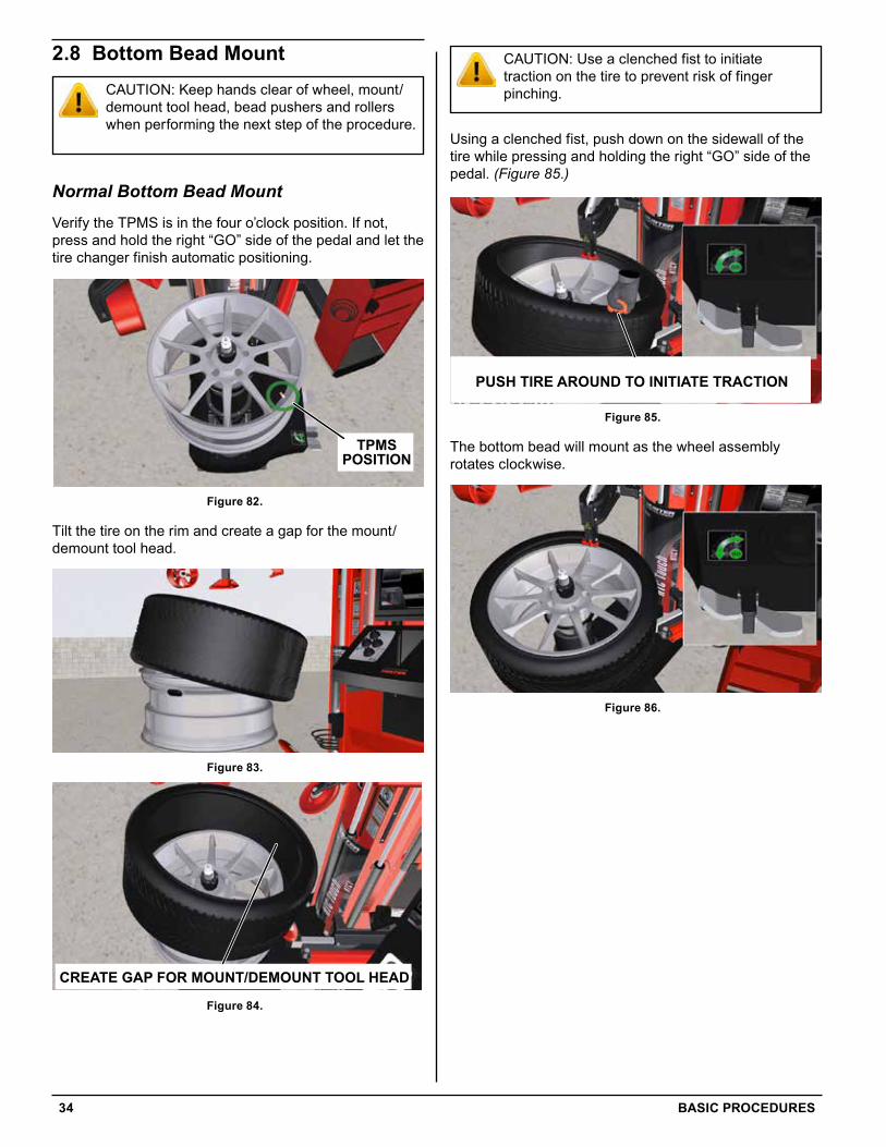
CAUTION: Use a clenched fist to initiate traction on the tire to prevent risk of finger pinching.
Using a clenched fist, push down on the sidewall of the tire while pressing and holding the right “GO” side of the pedal. (Figure 85.)
BOTTOM BEAD MANUALLY MOUNTED ON RIM
TPMSPOSITION
CREATE GAP FOR MOUNT/DEMOUNT TOOL HEAD
PUSH TIRE AROUND TO INITIATE TRACTION
BOTTOM BEAD ALREADY MOUNTED ON RIM
TIRE STALLED ON RIM
TOP BEAD OVER LEFT SIDE OFMOUNT/DEMOUNT TOOL HEAD
TOP BEAD UNDER HOOK
Figure 85.
The bottom bead will mount as the wheel assembly rotates clockwise.
Figure 86.
2.8 Bottom Bead MountCAUTION: Keep hands clear of wheel, mount/demount tool head, bead pushers and rollers when performing the next step of the procedure.
Normal Bottom Bead Mount
Verify the TPMS is in the four o’clock position. If not, press and hold the right “GO” side of the pedal and let the tire changer finish automatic positioning.
BOTTOM BEAD MANUALLY MOUNTED ON RIM
TPMSPOSITION
CREATE GAP FOR MOUNT/DEMOUNT TOOL HEAD
PUSH TIRE AROUND TO INITIATE TRACTION
BOTTOM BEAD ALREADY MOUNTED ON RIM
TIRE STALLED ON RIM
TOP BEAD OVER LEFT SIDE OFMOUNT/DEMOUNT TOOL HEAD
TOP BEAD UNDER HOOK
Figure 82.
Tilt the tire on the rim and create a gap for the mount/demount tool head.
Figure 83.
BOTTOM BEAD MANUALLY MOUNTED ON RIM
TPMSPOSITION
CREATE GAP FOR MOUNT/DEMOUNT TOOL HEAD
PUSH TIRE AROUND TO INITIATE TRACTION
BOTTOM BEAD ALREADY MOUNTED ON RIM
TIRE STALLED ON RIM
TOP BEAD OVER LEFT SIDE OFMOUNT/DEMOUNT TOOL HEAD
TOP BEAD UNDER HOOK
Figure 84.
BASIC PROCEDURES 35
If this happens, release the right “GO” side of the pedal. Readjust the tire position.
From the procedure wheel slide-out menu, touch “Retry”.
Figure 90.
Press and hold the right “GO” side of the pedal. The bottom bead mount procedure will repeat.
Additional Bottom Bead Mount Procedures
Bottom Bead Already Mounted
In many cases, the bottom bead can be manually mounted on the rim, speeding up the tire changing procedure.
BOTTOM BEAD MANUALLY MOUNTED ON RIM
TPMSPOSITION
CREATE GAP FOR MOUNT/DEMOUNT TOOL HEAD
PUSH TIRE AROUND TO INITIATE TRACTION
BOTTOM BEAD ALREADY MOUNTED ON RIM
TIRE STALLED ON RIM
TOP BEAD OVER LEFT SIDE OFMOUNT/DEMOUNT TOOL HEAD
TOP BEAD UNDER HOOK
Figure 87.
If this is the case, from the procedure wheel slide-out menu, touch “Continue - Bottom Bead Already Mounted”.
Figure 88.
Tire Stall on Rim
While mounting the bottom bead, if not pushed around, the tire may have a tendency to stall in place as the rim rotates.
BOTTOM BEAD MANUALLY MOUNTED ON RIM
TPMSPOSITION
CREATE GAP FOR MOUNT/DEMOUNT TOOL HEAD
PUSH TIRE AROUND TO INITIATE TRACTION
BOTTOM BEAD ALREADY MOUNTED ON RIM
TIRE STALLED ON RIM
TOP BEAD OVER LEFT SIDE OFMOUNT/DEMOUNT TOOL HEAD
TOP BEAD UNDER HOOK
Figure 89.
36 BASIC PROCEDURES
Using a clenched fist, push down on the sidewall of the tire while pressing and holding the right “GO” side of the pedal. The upper bead roller will lower the tire as the wheel assembly rotates clockwise.
BOTTOM BEAD MANUALLY MOUNTED ON RIM
TPMSPOSITION
CREATE GAP FOR MOUNT/DEMOUNT TOOL HEAD
PUSH TIRE AROUND TO INITIATE TRACTION
BOTTOM BEAD ALREADY MOUNTED ON RIM
TIRE STALLED ON RIM
TOP BEAD OVER LEFT SIDE OFMOUNT/DEMOUNT TOOL HEAD
TOP BEAD UNDER HOOK
Figure 93.
When the tire is mounted, all tools will move to their home positions.
Figure 94.
Using the Press Arms
The top bead on some tires may be difficult to mount. The tire and rim will turn but the top bead fails to mount.
TOP BEAD HAS FAILED TO MOUNT
ROTATE BEAD PUSHERS
BEAD PUSHERSLOWERED PUSHING
AGAINST TIRE
LIFT TIRE AND PRESS NOZZLE AGAINST RIM
ROTATE WHEEL ASSEMBLY 180°USE RUBBER PAD TO PROTECT WHEEL SURFACE
OVERHEAD VIEW
TPMS IN-LINEWITH ROLLER
OVERHEAD VIEW
TPMS NOTIN-LINE
WITH ROLLER
OVERHEAD VIEW
TPMS NOTIN-LINE
WITH ROLLER
Figure 95.
If this happens, release the right “GO” side of the pedal.
2.9 Top Bead MountCAUTION: Keep hands clear of wheel, mount/demount tool head, bead pushers and rollers when performing the next step of the procedure.
Normal Top Bead Mount
Tilt the tire on the rim so the top bead is over the left side of the mount/demount tool head, and under the bead hook.
BOTTOM BEAD MANUALLY MOUNTED ON RIM
TPMSPOSITION
CREATE GAP FOR MOUNT/DEMOUNT TOOL HEAD
PUSH TIRE AROUND TO INITIATE TRACTION
BOTTOM BEAD ALREADY MOUNTED ON RIM
TIRE STALLED ON RIM
TOP BEAD OVER LEFT SIDE OFMOUNT/DEMOUNT TOOL HEAD
TOP BEAD UNDER HOOK
Figure 91.
BOTTOM BEAD MANUALLY MOUNTED ON RIM
TPMSPOSITION
CREATE GAP FOR MOUNT/DEMOUNT TOOL HEAD
PUSH TIRE AROUND TO INITIATE TRACTION
BOTTOM BEAD ALREADY MOUNTED ON RIM
TIRE STALLED ON RIM
TOP BEAD OVER LEFT SIDE OFMOUNT/DEMOUNT TOOL HEAD
TOP BEAD UNDER HOOK
Figure 92.
CAUTION: Use a clenched fist to initiate traction on the tire to prevent risk of finger pinching.
BASIC PROCEDURES 37
The wheel assembly with pushers will then rotate clockwise as the top bead is fully mounted.
Figure 99.
When the tire is mounted, all tools will move to their home positions.
Figure 100.
Rotate the bead pushers fully counter clockwise.
TOP BEAD HAS FAILED TO MOUNT
ROTATE BEAD PUSHERS
BEAD PUSHERSLOWERED PUSHING
AGAINST TIRE
LIFT TIRE AND PRESS NOZZLE AGAINST RIM
ROTATE WHEEL ASSEMBLY 180°USE RUBBER PAD TO PROTECT WHEEL SURFACE
OVERHEAD VIEW
TPMS IN-LINEWITH ROLLER
OVERHEAD VIEW
TPMS NOTIN-LINE
WITH ROLLER
OVERHEAD VIEW
TPMS NOTIN-LINE
WITH ROLLER
Figure 96.
From the procedure wheel slide-out menu, touch “Retry”.
Figure 97.
Press and hold the right “GO” side of the pedal. The bead pushers will lower and push against the tire.
TOP BEAD HAS FAILED TO MOUNT
ROTATE BEAD PUSHERS
BEAD PUSHERSLOWERED PUSHING
AGAINST TIRE
LIFT TIRE AND PRESS NOZZLE AGAINST RIM
ROTATE WHEEL ASSEMBLY 180°USE RUBBER PAD TO PROTECT WHEEL SURFACE
OVERHEAD VIEW
TPMS IN-LINEWITH ROLLER
OVERHEAD VIEW
TPMS NOTIN-LINE
WITH ROLLER
OVERHEAD VIEW
TPMS NOTIN-LINE
WITH ROLLER
Figure 98.
CAUTION: Pushers will automatically rotate. Stay clear of assembly.
38 BASIC PROCEDURES
Figure 102.
The choices will cycle from psi;
Figure 103.
to disabled;
Figure 104.
to bar;
2.10 InflationDANGER: Activate blast inflation nozzle only when seating beads. Never point the blast inflation nozzle at yourself or others.
WARNING: Do not lean or reach over tire changer when inflating.
WARNING: Do not exceed this pressure limitation: BEAD SEATING PRESSURE (gauge on screen) 2.8 bar (40 PSI)
WARNING: Do not operate the blast inflation nozzle if the tire is not properly clamped.
CAUTION: Hold the blast inflation nozzle firmly. The nozzle has a kick-back and can strike the operator if not held firmly.
Changing Inflation Pressure Units
The inflation pressure units displayed can be changed by the operator. A choice of psi, bar, kPa may be selected. Additionally, the pressure unit display can be disabled.
To change the inflation pressure units:
From the main screen, touch “Utility”.
Touch “Set Up”.
Select “Maximum Inflation Pressure Setup”, then touch “Set Up Selected Item”.
Figure 101.
Touch the blue arrows in the “Select inflation units, or disable inflation” section.
BASIC PROCEDURES 39
Figure 107.
The bottom right interface tab shows inflation controls. Touch the left and right arrows above the pressure gauge to adjust the target air pressure.
Figure 108.
Touch the start button to begin inflation.
Figure 109.
After beads have been seated, disconnect inflation hose and reinstall valve stem core previously removed. Re-connect the inflation hose and inflate tire to the specified target pressure. Disconnect the inflation hose.
NOTE: The inflation procedure may be stopped by touching the STOP button on the bottom right interface tab.
Figure 105.
to kPa;
Figure 106.
Touch “OK”.
Touch “Store Set Up”.
The selected inflation pressure units will now be displayed. If “disabled” is selected, inflation units will not be displayed.
Normal Inflation ProcedureIf present, remove the valve stem core from the valve stem.
Connect the inflation hose to the valve stem.
40 BASIC PROCEDURES
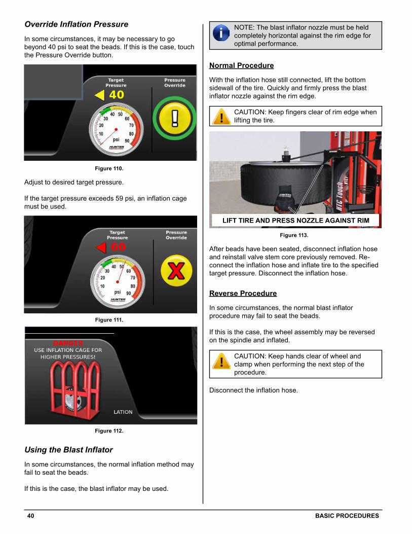
NOTE: The blast inflator nozzle must be held completely horizontal against the rim edge for optimal performance.
Normal Procedure
With the inflation hose still connected, lift the bottom sidewall of the tire. Quickly and firmly press the blast inflator nozzle against the rim edge.
CAUTION: Keep fingers clear of rim edge when lifting the tire.
TOP BEAD HAS FAILED TO MOUNT
ROTATE BEAD PUSHERS
BEAD PUSHERSLOWERED PUSHING
AGAINST TIRE
LIFT TIRE AND PRESS NOZZLE AGAINST RIM
ROTATE WHEEL ASSEMBLY 180°USE RUBBER PAD TO PROTECT WHEEL SURFACE
OVERHEAD VIEW
TPMS IN-LINEWITH ROLLER
OVERHEAD VIEW
TPMS NOTIN-LINE
WITH ROLLER
OVERHEAD VIEW
TPMS NOTIN-LINE
WITH ROLLER
Figure 113.
After beads have been seated, disconnect inflation hose and reinstall valve stem core previously removed. Re-connect the inflation hose and inflate tire to the specified target pressure. Disconnect the inflation hose.
Reverse Procedure
In some circumstances, the normal blast inflator procedure may fail to seat the beads.
If this is the case, the wheel assembly may be reversed on the spindle and inflated.
CAUTION: Keep hands clear of wheel and clamp when performing the next step of the procedure.
Disconnect the inflation hose.
Override Inflation Pressure
In some circumstances, it may be necessary to go beyond 40 psi to seat the beads. If this is the case, touch the Pressure Override button.
Figure 110.
Adjust to desired target pressure.
If the target pressure exceeds 59 psi, an inflation cage must be used.
Figure 111.
Figure 112.
Using the Blast Inflator
In some circumstances, the normal inflation method may fail to seat the beads.
If this is the case, the blast inflator may be used.
BASIC PROCEDURES 41
TOP BEAD HAS FAILED TO MOUNT
ROTATE BEAD PUSHERS
BEAD PUSHERSLOWERED PUSHING
AGAINST TIRE
LIFT TIRE AND PRESS NOZZLE AGAINST RIM
ROTATE WHEEL ASSEMBLY 180°USE RUBBER PAD TO PROTECT WHEEL SURFACE
OVERHEAD VIEW
TPMS IN-LINEWITH ROLLER
OVERHEAD VIEW
TPMS NOTIN-LINE
WITH ROLLER
OVERHEAD VIEW
TPMS NOTIN-LINE
WITH ROLLER
Figure 117.
Lift the wheel assembly back into operating position. Refer to “2.1 Using the Wheel Lift,” on page 21 for detailed instructions.
Clamp the wheel assembly. Refer to “2.2 Clamping the Wheel,” on page 22 for detailed instructions.
Connect inflation hose and set pressure. Refer to “The inflation pressure units displayed can be changed by the operator. A choice of psi, bar, kPa may be selected. Additionally, the pressure unit display can be disabled.,” on page 38 for detailed instructions.
With the inflation hose connected, lift the bottom sidewall of the tire. Quickly and firmly press the blast inflator nozzle against the rim edge.
CAUTION: Keep fingers clear of rim edge when lifting the tire.
Figure 118.
After beads have been seated, disconnect inflation hose and reinstall valve stem core previously removed. Re-connect the inflation hose and inflate tire to the specified target pressure. Disconnect the inflation hose.
From the procedure wheel slide-out menu, touch “Unclamp” or press the right “GO” side of the pedal.
Figure 114.
Depress the button on the top of the clamp and remove the clamp from the rim.
Figure 115.
Lower the wheel lift by pressing and holding down the left side of the pedal. Release the pedal when the wheel assembly contacts the ground.
Figure 116.
NOTE: Be sure to use the included rubber protector pad to prevent damage to the face of the rim.
Remove wheel assembly and flip it over so the face of the rim now faces the spindle. Reposition the wheel assembly on spindle.
42 BASIC PROCEDURES
2.11 UnclampFrom the procedure wheel slide-out menu, touch “Unclamp” or press the right “GO” side of the pedal.
Figure 119.
Depress the button on the top of the clamp and remove the clamp from the rim.
Figure 120.
Lower the wheel lift by pressing and holding down the left side of the pedal. Release the pedal when the wheel assembly contacts the ground.
Figure 121.
ADVANCED PROCEDURES 43
3.1 Using the Flange PlateCertain circumstances require the use of a flange plate. Clad wheels and reverse drop center wheels are the most common uses of the flange plate. This section will cover the proper flange plate set-up and clamping procedures.
5 Lug Clad Wheel
Clad wheels must be serviced using a flange plate to prevent damage to the plastic clad surface.
Figure 122.
Never clamp a clad wheel directly with the clamp. Doing so will break the plastic where the clamp contacts the wheel.
Figure 123.
3. Advanced Procedures
44 ADVANCED PROCEDURES
Move the remaining pins to the 5 lug holes.
Figure 127.
Figure 128.
Figure 129.
Figure 130.
Configure the Flange Plate
Configure the flange plate for a 5 lug pattern.
Figure 124.
Keep the silver screw pin in place.
Figure 125.
Remove one pin.
Figure 126.
ADVANCED PROCEDURES 45
Install clamp. Do not use clamping cone and ensure the clamp is positioned all the way at the top of the clamping shaft.
Figure 134.
Press and release the right “GO” side of the pedal to clamp.
Figure 135.
6 Lug Reverse Drop Center Wheel
Reverse drop center wheels must be serviced using a flange plate to prevent damage to the rim surface.
Configure the Flange Plate
Configure the flange plate for a 6 lug pattern.
Figure 136.
Tighten the pins in place.
Figure 131.
Adjust the pins to fit the lug pattern.
Figure 132.
Set Flange Plate and Clamp
Position the flange plate pins through the lug holes and verify the pins are contacting the spindle backing plate.
Figure 133.
46 ADVANCED PROCEDURES
Secure Flange Plate
Position the flange plate pins through the lug holes on the front face of the rim.
Figure 140.
From the back side of the rim, secure the flange plate using 2 thumb screws.
Figure 141.
The wheel is now ready for service.
Figure 142.
Using the previous method for setting the pins, configure the flange plate for a 6 lug pattern. Once configured, tighten the pins in place.
Figure 137.
Remove Backing Plate Assembly
Remove the backing plate assembly from the tire changer spindle. Simply lift the assembly and set it on the storage peg on the side of the tire changer cover.
Figure 138.
Figure 139.
ADVANCED PROCEDURES 47
Figure 146.
The wheel will drop down into place when properly aligned.
Figure 147.
Install clamp. Use the clamping cone with the appropriate side down to ensure contact with the rim. Slide the clamp all the way down the clamping shaft so the cone contacts the rim surface.
Figure 148.
Lift and Clamp
Position the flange plate on the spindle and lift the wheel into the vertical position.
Figure 143.
Figure 144.
Rotate the wheel to align the index holes on the spindle with the index pins on the flange plate.
Figure 145.
48 ADVANCED PROCEDURES
3.2 Using the Dual Wheel Adaptor KitSome large center hole wheels, such as dually wheels and 19.5” wheels can be clamped using the 20-2964-1 Truck Dual Wheel Adaptor kit.
16” GM Dual Wheel Procedure
Install the adaptor plate, engaging the anti-rotation pin in the platen.
Figure 150.
Install the wheel onto the plate and line up a stud hole with the slot in the plate.
Insert the traction pin through the lug hole and into the adaptor slot.
Figure 151.
Install the top cone, aligning it with the traction pin.
Press and release the right “GO” side of the pedal to clamp.
Figure 149.
ADVANCED PROCEDURES 49
Figure 155.
Install the wheel onto the plate, make sure the wheel’s locator pin is clocked to one of the flat sides of the adaptor plate.
Install the traction pin through the lug hole into the adaptor slot.
Figure 156.
Install the top cone, aligning it with the traction pin.
Secure the wheel using the small cone on the Quick Clamp.
Figure 157.
Proceed normally through the tire changing process.
Figure 152.
Secure the wheel using the small cone on the Quick Clamp.
Figure 153.
Proceed normally through the tire changing process.
16” Ford Dual Wheel with Stud Procedure
Look for the locator pin on the inside face of the wheel. Note the pin’s location.
Figure 154.
Install the adaptor plate, engaging the anti-rotation pin in the platen.
50 ADVANCED PROCEDURES
Figure 161.
Install the centering cone and Quick Clamp.
NOTE: Make sure the centering cone is seated properly inside the center bore of the wheel.
Figure 162.
Example of an incorrectly seated centering cone.
Figure 163.
19.5” or other Large Bore Wheel Procedure
Install the adaptor plate with the adaptor slot clocked slightly counterclockwise from the anti-rotation pin notch in the platen.
Figure 158.
Rotate the adaptor clockwise. The cap screws will drop into the notch in the platen as shown, locking the adaptor to the platen.
Figure 159.
Line up a lug hole with the slot in the adaptor.
Figure 160.
Install the traction pin through the lug hole into the adaptor slot.
MAINTENANCE 51
4. Maintenance 4.1 Maintenance ScheduleCAUTION: Do not hose down or power wash the tire changer.
Proper care and maintenance are necessary to ensure that the tire changer operates properly. Proper care will also ensure that rims and tires are not damaged during the mount/demount process.
Daily• Turn the tire changer power off at the end of the work
day. At a minimum, depress the emergency stop switch
• Never leave a wheel assembly on the tire changer overnight. Always remove all assemblies and ensure tools are returned to their home position
• Check for worn or damaged rubber and nylon components that should be replaced to prevent damage from occurring. Replace worn parts as needed (rubber pads and blocks, rollers, and mount/demount head)
• Clean all areas that contact rims or tires to prevent possible scratching to rim.
Weekly• Clean the tire changer with shop towels or a vacuum
cleaner. Do not clean with or use compressed air, which can blast dirt between moving parts.
• Do not use cleaning solvents to clean pressure regulator/oiler.
Annually• Change hydraulic fluid and filter once per year.
Contact your Hunter Service Representative for this service.
Periodically• Refill the pressure regulator/oiler using only
Hunter Lubri-oil as needed. Petroleum-based oils should never be used in the oiler and may void all warranties.
• Check for loose bolts and tighten per specifications. Contact your Hunter Service Representative for information.