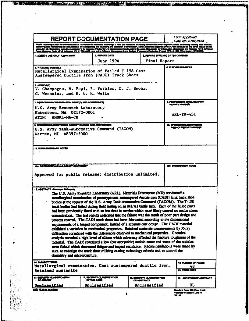
REPORT DOCUMENTATION PAGE Form AppiOWJd Oi.AS No. 0704.0188 ..._ ....... ____ ., ____ ..... ,_ .... ..... ,_,. .. ___ ..,. __ _,.._,. __ ....... - .... ---- .... -===---- ... ----- I ........ ....... 1211,..._ o.. .-d'X. - -- ,.. ac-. 1. MJDCY-.a&.Y __ _., I. _...,.,.,.._Co\1D CCWIMD June 1994 Final Report .. mu ... ..mu LPI.-.ca- Metallurgical Examination of Failed T-158 Cast Austempered Ductile Iron (CADI) Track Shoes • .. All'niORCI) v. Champagne, M. Pep!, B. Pothier, D. J. Snoha, G. Wechsler, and M. G. H. Wells ?.P'IIIIOl ....... L FiiiW':-111 OMIAIIIZA11011 IWJ'Oin'- U.S. Army Research Laboracory Watertown, MA 02172-0001 ARL-TR-451 ATrN: AMSRL-MA-cB ... .... .., ... , 111.... :'1 ..................... a•a 11 c • MI!1'DI•ra U.S. Army Tank-Automotive Command (TACOM) IIIDII:r ..... ,. .... Warren, MI 48397-5000 . . ........ 1 ruw.,.. . , .. ..,..,...cooe Approved for public release; distribution unlimited. ti. ... MoCT .......... _ Tbe U.S. Army l.lbaniDiy (ARL), MaieriaiJ DhidOIIIe (MD) conducleCl a lllleCIIIaqicalaami"""" af JM«**tJPI cat w-mpeaed ducdJe iron (CADI) t.ulk b'IICt sboe "bodia a tbe·requcst afdle U.S. Army Tlak·AIIIDIIIOdve Command (I'ACOM). The T-158 lid bodielllld tailed cluriDa field ... GilD Ml/Al billie llllk. Each of tbe failed pariS llld beea pmYiously ftDed tridla ice dell iD wldcb _,.. utdy cauml an undue sttess CDIQiibadoa. 'l'be tat telllhs iadiciN lbat die fiilure Wit the result of poor put claip and • process COJlll'CIL The CADI triCk sboes t.l beeD rabraled ICCOidbta to the dimensioaal reqailaaalls ol a forpd conlpODCDI. ia.tJiad of a .,., ..... , c:ast claip. 1be CAD[ material exhibited a valaticrl ia.mecbllrical propc:nies. Retained llllleftite measurements by X-ray difftu:daa CIX'Idattd 'lri!b the diffenllces absented in medlaniQJ properties. Chemical ...,._ m..aled a blab liNd olliUcoa wtdch advenely aft'ected tile fracture , .... ,_of the 'l1le CADI coltllaed a low (but nodule c:cuat aad 10111e of the nodules ._. ftab4 wllicb decrelaxl &lip aad implct resilllllCe. Recommeodldons were made by ARL 10 redelip the b'IICt lboe udlizinl c:asdnJ lecbnoloay criteria and ro control die c:t.Diatry aad lllicmlbUCIIUe. a -.cr-.- ·- , .. --:: ..... Metalluraical examination. Cast austempered ductile iron, RetaiDed austenite t&I'IIICaCOM ... ..-wa ICA1IDII tLIICUIIn'YQ '11JIICA1t01t 1LIICUN1\' CUIII'ICA11011 .. LM'rA'ftONOI' MI1MCT ., ..... , 01',..,.. 01' MI1'IWIT tJDelalaj._fied Unclassified Unclassified UL ";;· ... , ..... _ .................. ,..., i
1. MJDCY-.a&.Y __ _., I.~DAft I. _...,.,.,.._Co\1D CCWIMD
June 1994 Final Report .. mu ... ..mu LPI.-.ca-
Metallurgical Examination of Failed T-158 Cast Austempered Ductile Iron (CADI) Track Shoes
• .. All'niORCI)
v. Champagne, M. Pep!, B. Pothier, D. J. Snoha, G. Wechsler, and M. G. H. Wells
?.P'IIIIOl 111-liOII~.uea:: ....... L FiiiW':-111 OMIAIIIZA11011 IWJ'Oin'-U.S. Army Research Laboracory Watertown, MA 02172-0001 ARL-TR-451 ATrN: AMSRL-MA-cB ... .... .., ... , 111....:'1 ..................... a•a 11 c • MI!1'DI•ra
U.S. Army Tank-Automotive Command (TACOM) IIIDII:r.....,. ....
Warren, MI 48397-5000 . . ........ 1 ruw.,.. .
,.~.,..~ , .. ..,..,...cooe
Approved for public release; distribution unlimited.
ti. ... MoCT .......... _
Tbe U.S. Army ~ l.lbaniDiy (ARL), MaieriaiJ DhidOIIIe (MD) conducleCl a lllleCIIIaqicalaami"""" af JM«**tJPI cat w-mpeaed ducdJe iron (CADI) t.ulk b'IICt sboe
"bodia a tbe·requcst afdle U.S. Army Tlak·AIIIDIIIOdve Command (I'ACOM). The T-158 lid bodielllld tailed cluriDa field ... GilD Ml/Al billie llllk. Each of tbe failed pariS llld beea pmYiously ftDed tridla ice dell iD ~ wldcb _,.. utdy cauml an undue sttess CDIQiibadoa. 'l'be tat telllhs iadiciN lbat die fiilure Wit the result of poor put claip and
•
process COJlll'CIL The CADI triCk sboes t.l beeD rabraled ICCOidbta to the dimensioaal reqailaaalls ol a forpd conlpODCDI. ia.tJiad of a .,.,....., c:ast claip. 1be CAD[ material exhibited a valaticrl ia.mecbllrical propc:nies. Retained llllleftite measurements by X-ray difftu:daa CIX'Idattd 'lri!b the diffenllces absented in medlaniQJ properties. Chemical ...,._ m..aled a blab liNd olliUcoa wtdch advenely aft'ected tile fracture ,....,_of the ~ 'l1le CADI coltllaed a low (but ~le) nodule c:cuat aad 10111e of the nodules ._. ftab4 wllicb decrelaxl &lip aad implct resilllllCe. Recommeodldons were made by ARL 10 redelip the b'IICt lboe udlizinl c:asdnJ lecbnoloay criteria and ro control die c:t.Diatry aad lllicmlbUCIIUe.
3. Sctwrnatk: shoiNirG clrnensians of the CADI track shoes........................................... 1 8
4. Schematic showing regions of clntensionld inspection for ~db~traclc'~ ............................... ~ .......••. ~ ......•.......... , .................... 18
s.)Maaosraph showing ... of rrJninun tf1idG'MISS on h ~ tlll»e (,}/ 1:r8C:k sl1oe #R6.................................................................. ......... 1 9
6. Mlc~ showing thickness of the #R6 binocular tube on the grotl'1d side....... 1 9
1 •. ttllc~ showing filled half of track shoe #L30 ............................................... ZO
8. Schatiltlc showing method used to section the fracture swfllc:es apart from ~ tllae: 'M-30 ................................................ -................................................... z 0
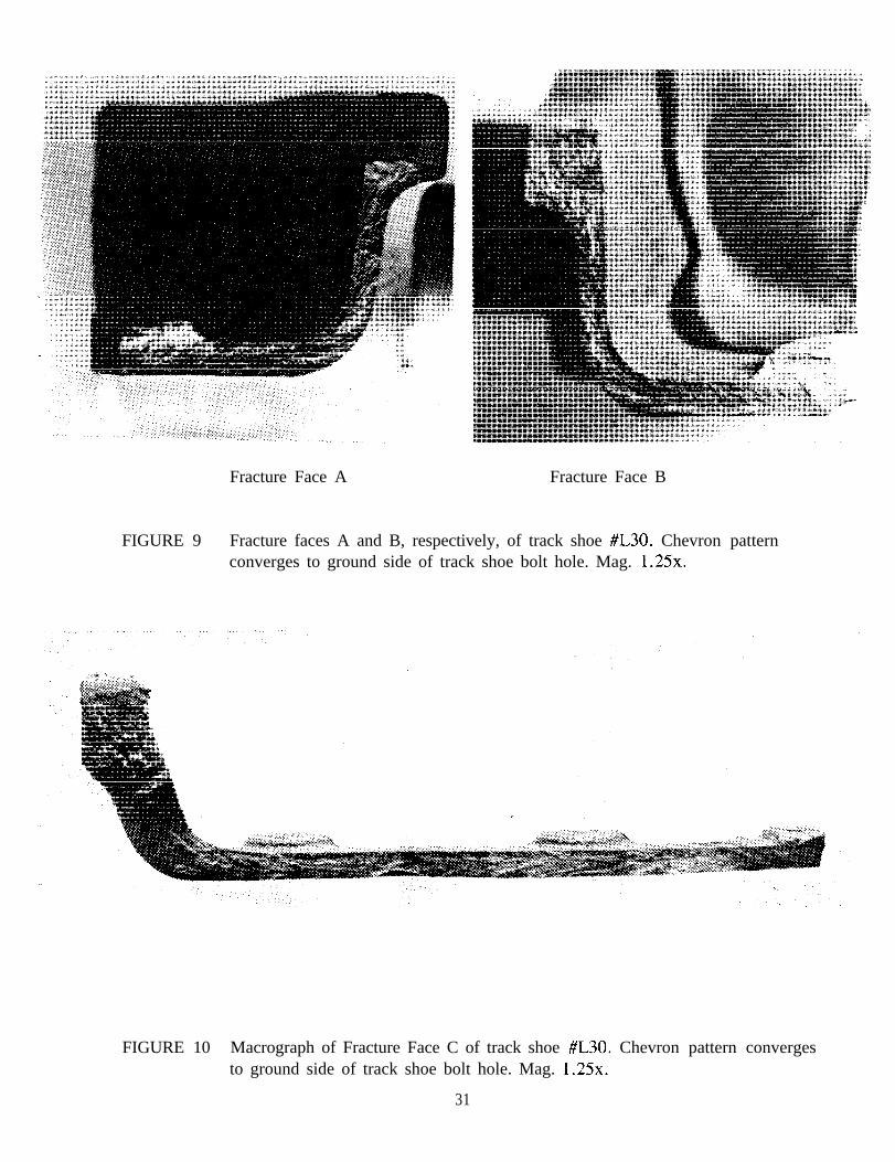
9. Frlc:twe '*-A and B. ~. of tnldc shoe #l30. Chevron pattern CCJI1'j~ 1:0 graJrtd slc:le r;,f tr8Cic sfiC)8 bolt 11de ••••••••••••••••••.• ·•••••·•··· ••.••••••••••••••••••• z 1
Iii
'1 0. Macrograph of fracture face C of track shoe #l30. Chevron pattern converges to ground side of track shoe bolt hoie........................... ............. ............. 2 1
11. Fracture face 0 of track shoe #L30. Chevron pattern converges to ground side of t.rac:k 'St1oe bolt hole...................................................................................... 2 2
12. Magnified view of the crack extending from the bolt hole of track shoe #L30 (ground side) .......................................................................................................... 2 2
1 3. Magnified view of the Wlderside of the cracked bolt hole of track shoe #L30 (wheel side) ..• : ............................................................................ 23
14. Comparison of the bolt holes of each track shoe....................................................... 2 3
1 5. Blacldight photograph showing wear on underside of bolt hole .......... ~ ............... ·...... 2 4
16. Ent.gernellt d the crack origin on fracture face& ................................................. 24
17. Macrograph of fracture origin on fracture face D ............ :...................................... 2 5
19. End view of track shoe #R6 showing cracking ............................ ... . .................. ...... 2 7
20. Schematic showing method of sectioning for the fracture sufaces
of track. ~ #R6 ·····-····-·············:···-···································································· 2 7
21. Photo montage showing frac:ttre faces A and C......................................................... 2 8
22. Jlt1o.t.o montage showing tr.:tl.l'e faces B ll1d D ......................................................... 29
23. Fracture origin of fnlctln face A, of track shoe #R6 ............................................ 30
24. Frac:twe origin of fnlc:twe face B, of track shoe #R6 ............................................ 30
25. SEM of corroded fractunJ swface showing ,...,..,t "mud-cracking" .................. 31
26. SEM showing representative morphology of • less corroded region of the frac::tlwe ..-fac:es .... _...... •••• ••••••••• •.••••• •• ....... •••• •••••• .• ••••••• •• .• . .. .. .••• .• •. .• .• •.•.... •• . 3 1
27. SEM showfng .._ of ductle cJmples suggesting ov.-loed faihn ........................... 3 2
28. SEM of another.-. of ductle dimples noted on • less corroded region of the ~ ~ ..................................................................................................... 32 •
29. Low rMgniftcation SEM photagnlph of the hcbn Ufllce of • laboratory test:ed lrr'lf:*:;t ~ _............ ........... •• ................. •••••••••••••••••••• •• •••• •• •••• •• •••• •• ••• •• •• 3 3
30. High rn.gniflcatlon SEM photograph of the fnlct\n surface of • laboratory ~~~··········· .. ·•········· .. ·•·· ............................................................... 33
31. Schematic of .etbllng ..,_n far~ Mel Altlllned austenite . ••'PI• from tndc thoe M.30. Sim11M' lp8Cimens were tectioned -frc:lln triiCic 11108 fiR6 ............................................................................................... 34
IV
' ~ ! : l • ' ' • ' • i • j I
~
! ! ' ' I I I I I l I l ~ I
l l
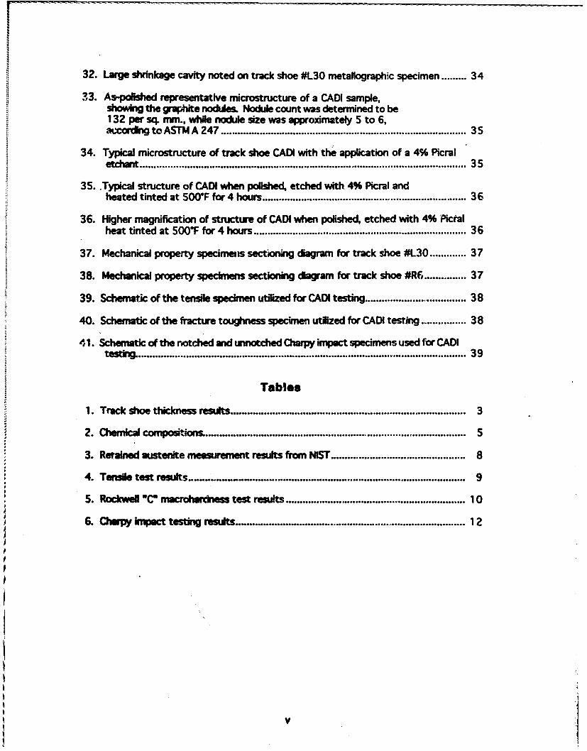
32. large shrinkage cavity noted on track shoe #L30 metallographic specimen ......... 34
33. A~ representative microstructure of a CADI sample, showing the graphite nodules. Nodule count was determined to be 132 per sq. nvn., while nodule size was approximately 5 to 6, accordngtoASTMA 247 ........................................................................................ 35
34. Typical microstructure of track shoe CADI with the appCication of a 4% Picral et:da1t ·•···· ........ ~· ............................................................. ~·········· .. ··················· .. .... .. . 3 5
35 .. Typical structure of CADI when polished. etched with 41)6 Picral and heated tinted at 50<rF for 4 hours ......................................................................... 36
36. Higher magnification of structwe of CADI when polished, etched with 41)6 Picral heat tinted at 500~ for 4 hours ....... •••.• .•••.••.••••• .• .••.• .............. •... .• ............. ..... .. ..•• 3 6
. 'll.e U.S. Army Tank-Autornodve Command (TACOM) has investiguted the possible use of cat austempeted ductile irr.xt (CADI) trar.:k shoe bodies for tbe Ml Abrams and Bradley ''fanb. An FY90 TACOM program (CADI Tal'\k Track) called for the development of CADI T-158 track shoes for use on the Ml Abrams tank. The objective of the track shoe program was to reduce the weight and/or cost of track shoes by replacing the forged parts currently u.sed in the field, with those fabricated from CADI. A competiti"e contract for the production ofT-.lS8 track sbr.e assemblies with CADI shoe bodies was awardfxl to a contractor on Siptt:oa:ber 26, 1990.
An tsitire strand of the T -ISS tmck with the CADI shoe bodies was deliven:d to Ft. Greely, Al&sb for fiekl fating at the U.S. Army Cold Regkm Test Center. Testing consisted of operatinc a t'J-ton M 11 A l battle tank throu&h mobHe operations over a variety of terrain during tbe winter-periocl of 1991-1992 [1]. One side of the vehicle hacl the CADI track while the normal fielded track (with steel shoes) was movnted on tlr: other side. Ternperaturc.-, during tbe tat period ranged from +47.P to -S2of. Daily inspections of the track were performtXI during mobility testing, ancl failed CADI track shoe assemblies were replaced &'
needed. F"tve CADI track shoes failed during tlte mobility test and were replaced. Visible ct~Ckirta of the shoe body was used as the failure criteria. Two additional CADI shoe bodie.1 were found to be cracked during the fmal inspaon after mobility testing. The aiCCUmulated mile'ap of each failed track component was recorded.
AJq with the CADI T-158 shoe bodies, Jeverai other prototype components were ir.stalled an the wbide during d1e cold regions field tat. A modified ice cleat design wa.tS attached to every sixth tniCk shoe in each ShaDd during the mobility testing. It is important to note that ice cleats bad been attached to every CADI T -lSI track shoe body which failed at Ft. Greely. None of tbe shoe bodies without an ice cka1 attacMd failed. After cold regions testing, the CADI 1'-158 track VJU shipped to Ywna Proving Ground (YPG) for additional mobility testirlg. Four of the CADI i-158 slw.Je 'JOdies fa.iled durin& these mobility tests at YPG. Whether these fai1eci track shoes weT'..; previousJ.y fitted with ice cleats while at Ft. Greely W'.!S ·
unrecorded. These four failutes were not examined in this investigation.
After sew:ralmoath.,, two of the leYell failed CADI triCk shoe bodies (Ft. Greely) were st~t to the U.S. Army Resean:b Laboralory-Mar.eriab Directorate (USARL-MD), Watertown, ~ for post-ea:.-ice aysis. Ftpre~ 1 and 2 sbow both of tbt.:se track shoes in the ~ c:or..dition. Fapre 1 shows Track IL30 '(Ft. Greely designation stamped into shoe), while Fipse 2 shows Tract IR6 (a!Jo Pt. GNely desipation). Track 11..30 travelled 59 kilometers before failure, while Tnlck IR6 travelled 1239 Jdlometen betOI'e failure.
Tbe f«&ed seed Ml track shoe is cumndy flbricaled per U.S. Army Tank·Automotive · O.nMd (TACOM) BnPeainl Drawin& No. 12348383. nus drawina requires the lllllerlal to be slleel, foi'Jiftl alloy AISI 8640 or AISI8740 GradeD, according to
I
MIL-S-46172. The forged stee: is subsequently austenitized, quenched and tempered to a lt..anlness of 30-37 HRC. However, the track shoes under investigation were fabricated from CADI to the requirements of ASTM A 897[2] Grade ls0/10017. The dimensions utilized in the fabrication of the track shoes by the contractor are shown in Figure 3. These dimensions were listed in a contractor report which was generated as pa,.rt of their investigation of CADI as a track shoe alternative material. A contractor representative verified these dimensions, and also itx'!cated that the CADI track shoes were fabricated in accordance with the forged steel drawing (TACOM Engineering Drawing 12348383). Initially, CADI Grade 175/125/4 (also known as Grade 3) was selected, however, this was revised by the contractor in an effort to improve toughness, while maintaining yield and tensile properties competitive with forged steel. The cast ~uctile iron track shoes were subsequently austenitized at 1650-F for 1-1/4 hr. and austempered at 625-F for 1-3/4 hr., for a target hardness range of 341-444 BHN (Grade 3). Specification ASTM A 897 states that this hardness range is not mandatory, and is listed for informatioo only.
Dimensional Verifu;ation
1be diMensions of the track shoe were inspected near the fracture origin region of each f&iled component. Track shoe #1..30 failed at the bolt hole on the ground side (the only track shoe out of ~eral failures to exhibit this type of fracture), while track sboe #R6 cracked along tht~ "bioocular tubes• on the ground side (the most prominent mode of fracture). Figure 4 shows schematically tbe regions where the dimensions were inspected for each of the failed track sboes. The dimensions for these areas were taken from the report generated by the contractor, whicb contained tbe drawings from which tbe track shoes were fabricated. The minimum allowable thickness of material adjacent to the bolt hole (cract initiation location of Track IL30) on the ground side is 0.33 +0.04/.0.02 inch (tolerance taken from U.S. Army Tank-Automotive Command (TACOM) Engineering Drawing No. 12348383, and also from the contractor report). This thickness niJTOW1 to 0.20 +0.04/.0.02 inch in some areas on the ground side. Track shoe #L30 met the minimum thickness requirements in this region.
Tbe minimum allowable thickness of material in the center boss rqion of the •binocular tube• (crack initiation location of Track IR6) acconting to the contractor representative is:
(2.2,.- (t.9Q6• + 0.01,.)] = 0.1745. 2
Apia, this is tbe same minimum ;;:Jowable thickness noted on TACOM Engineering Drawing No. 12348383 for aforged componenL Since the thickness varied around the diameter of the tube, a.cropaphs were taken of a representative cross section showing the area of minimum tbidcness and the ground side thickness for Track #R6. Figure 5 shows the area of minimum tldckraesl of triCk shoe IR6, while Figure 6 shows the thickness at the ground side. The tblcbea of these regions was measumJ directly from the photomicrographs, at a ~ of lOx. The thickness results are listed in Table 1, as well as the minimum llloweble criteria from TACOM drawing No. 12348383.
Table 1 Track Shoe Thickness Results
Track Shoe
#R6 ground side
#R6 minimum
Thickness !inml
0.153
0.138
Minimum Allowable Thiclcness finch)
0.1745
0.1745
The thickness measured (the ground side and minimum thickness) at the •binocular tube• region of track shoe #R6 was below the minimum requirement specified on the forged conrponmtdrawing by as much as 20%.
Figure 7 shows the failed half of the track shoe. The location of the crack was on the ground side. The track shoe was sectioned in order to examine the fracture surfaces, as shown SchematicaUy in Figure 8. These fracture surfaces were labelled A, B, C and D for identification purposes. Each fracture surface was coveml with a vast amount of corrosion products, inGicating a prolonged exposure to the environment. Figure 9 shows fracture ~ A and B respectively. Fracti.R face Cis shown in Figure 10, while fracture faceD is shown in Figure 11. Although the fracture faces ~ covered with corrosion, fractographic features were still discemable. The chevron patterns and river markings of eaeh fracture surface indicatrd the fracture initiated at the OOI.t hole (ground side). Figure 12 shows a magnified view of the crack through tbe bolt bole region (ground side). This hole is utilized to attach the ice cleat to the track shoe. rlllft 13 shows a magnified view of the unc:temde of the cracked bolt hole region (wheel side). This hole was examined, in order to reveal anomalies which may have cootributm to crack initiation. It was noted that the top 1/16 inch of this hole con1ained what appeared to be a start of a thread (Figure 12). The T ACOM drawing for a forged component does not require this bolt hole to contain threads or a chamfer, as it is solely a through-hole. Figure 14 shows the comparison between the bolt hole of track shoe #R6 and that of track shoe #L30. The bolt bole of track shoe #R6 contained no such markings. In addition, significant wear was noted on the underside of the hole, most likely the result of a washer or bolt bead. Magnetic particle inspection was performed on this hole to reveal possible evidence nf cracking. Figure IS is a hlacldight photograph showing the wear, as well as a crack (u denoCed by the arrow). Figure 16 is a photomicrograph of the fractu~ origin, is noted on Fracture Face B. Figure 17 shows an enlargement of the crack origin, as noted on Fracture Face D.
Fipre 18 shows the failed balf of the track shoe. The crack initiation site occurred on the &round side of each binocular tube. Figure 19 sbows an end view of the cracking. Figure 20 ICbemadcally illUstrates the method of sectioning for the second failed track shoe. The fracture faces were labelled A, 8, C and D. SegmentAl broke into two pieces upon sectionina, and was labelled as Ala and Alb. As with track shoe IL30, the fracture surfaces were heavily corroded, but some fractographic features were still discernible. Figure 21 is a mootaae showing fracture face A and fracture face C. The chevron pattern and river markings iDdicated the fractule initiated in the region designated by the arrow. This region was on the &round side of the track shoe. Similarly, Figure 22 is a montage of fracture face Band D. Apin, the chevron pattern and river markings revealed the fracture origin to be the location designated by the arrow. Figures 23 and 24 are magnified views of the fracture origins (from fracture face A and B , respectively). No obvious surface anomalies were noted at either of the fracture origin sites.
Tbe fracture surfaces of each of the failed track shoes were examined utilizing the scanning electron micmecope. Figure 25 sbows the difficulty encountered, due to the corroded surfaces. This photomicrograph shows the "mud cracking" feature of the surface. The fracture surface was chemically cleaned, revealing a more discernible morphology. Figure 26 shows the fracture morphology of a less corroded region. Note the craters where the graphite spheroids have been pulled out. The surface appears to have failed in cleavage. Areas of clucti1e dimples were noted, and are sbown in Figures 27 and 28. These dimples are associated with a ductile faillft which could occur during overload. ·
Por comparative purposes, the fracture surfaces of laboratory tested tensile and impact specimens were examined utilizing the SEM. Both the tensile and impact fracture surfaces were similar. Figure 29 shows the fracture surface of an impact specimeu at low mapification. Note the graphite spheroids, and the pits left by the pulled-out spheroids. F~p~e 30 shows this region at higher magnification. Note the ductile dimples surrounding the gmpbite spheroids.
Chemical Analysis
The track sboes wen= specified to be fabricated from cast austempered ductile iron conforming to the NqUirements esblblisbed in ASTM A 897. Although this specification does not list specific chemical requimnents, it is stated that such rtquimMnts mt1y be agrted upon between 1M ~rand IM purrllllser. The chemical compositional requirements established by the manufacturers are listed in Table 2, as well as the chemistry of each component. Atomic ablorption and inductively coupled argon plasma emission spectroscopy were utilized to determine the chemical·composition of the alloy. The carbon and sulfur content was analyzed by the Leco combustion method. Samples representing a "thick" and "thin" section of the c:altinp were analyzed from each of the two failed track shoes. In general, the composition of the material under investigation compared favorably with the acceptable criteria, although the
4
r f
f I
~
t§lld..
siJicoll content of each track shoe was slightly higher than specified. Also noted, was the fact tbat cluomiu~q, molybdenum, titanium and copper were all higher than the residual criteria for -=b triCk sboe. Hip levels of these elements may be attributed to the scrap iron used in the ADI melt. 1be material tiom Track 130 Thin, had an abnormally hip chromium level, which wu very much in excess of the residual acceptance criteria. AlthoUgh having minimal affect on mechaDical properties, this excess in particular elements suggests a poor chemical control on behalf of the manufacturer.
Jeaions ~ting •thin• and •thick• areas of the casting were sectioned from each of the failed track shoes and prepared for metallographic examination, as shown schematically in Fijun= 31. 'Ibis diap'am shows a total of eleven samples which we~e sectioned from a portion of faiJed track shoe IL30 for metallographic samples and retained austenite measurement samples. Similar specimens were sectioned from track shoe #R6. Examination in the as-polished condition and at low magnification (12.5x) revealed a very large shrinkage cavity within a thick Mgion from. track shoe IL30, as shown in Fi~ 32. The graphite spheroids ~ shown to be evenly distributed within the matrix (Figure 33). The nodules differ in size sipificandy which suggests that some may have formed early in the casting process while other formed later by post inoculation. However, the difference in sizes could also be due to a •slicing effect•, in which different portions of the randomly distributed nodules were sectioned. In addition, some flalced nodules we~e noted. In excess, these irregularly shaped nodules ~ undesirable, since the larger surface to volume ratio raises the notch sensitivity and lowers the fatigue and impact resistance of the casting. Figure 33 was used to classify the graphite size per ASTM A 247[3], Method for Evaluating the Microstrut:ture of Graphite in 11011 Ctutings. The average graphite dimension measured was within the S-6 size class. The averaae nodule count measured from three samples of each track shoe was approximately 132 per sq. mm. nodules, which is considered acceptable. altbouah sligbdy less than optimal for Grade 150110017 CADI.
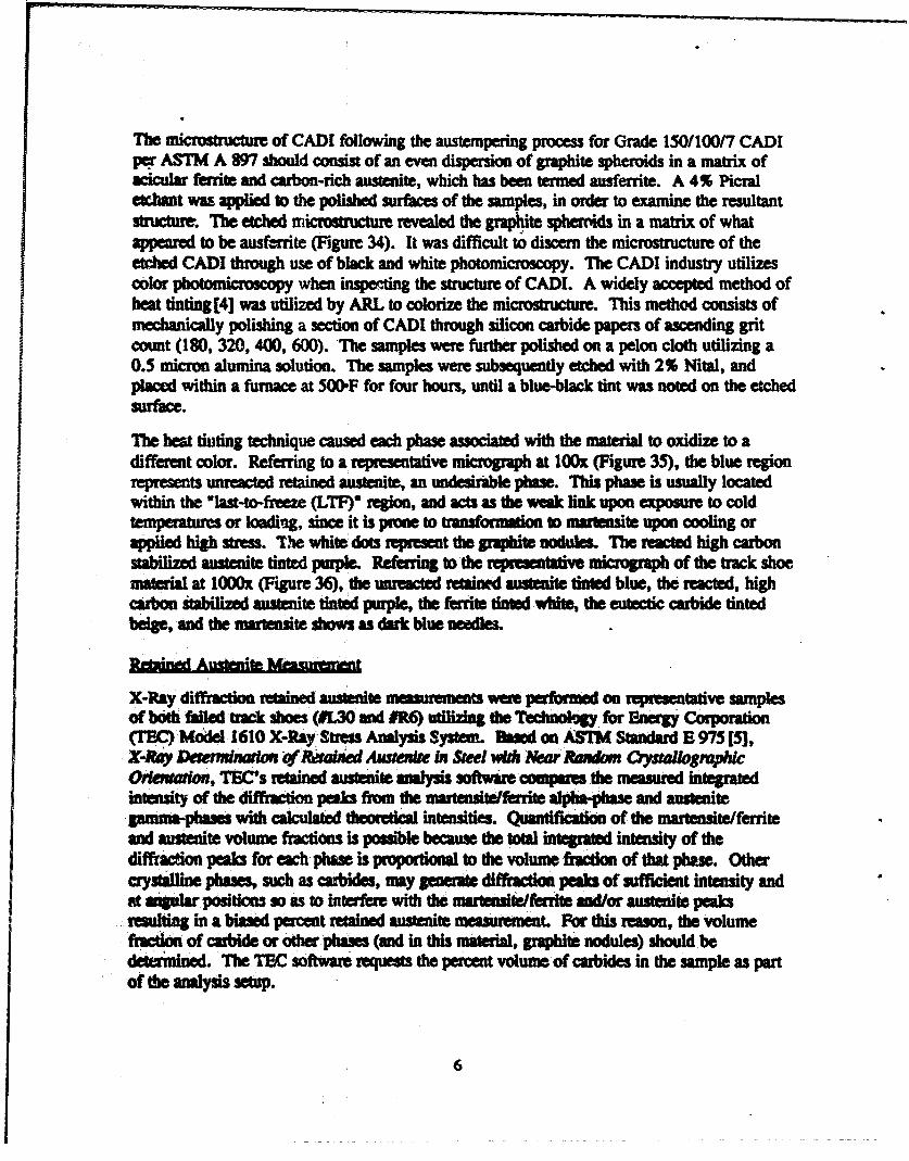
The microstructure of CADI following the austempering process for Grade lSO/tOOn CADI ~ ASTM A 897 should consist of an even dispersion of graphite spheroids in a matrix of •cicular ferrite aDd carbon-rich austenite, which has been termed ausferrite. A 4" Picral «*btmt was applied to the polished surfaces of the samples, in order to examine the resultant structute. The eftbed microstructuJe revealed the graphite ~ in a matrix of what appeared to be ausf:rrite (Figure 34). It was difficult tO discern the microstructure of the etdled CADI tJuouah use of black and white photomicroscopy. 1be CADI industry utilizes c:Oior pbotomicrosc:op when inspe!:ting the structure of CADI. A widely accepted method of beat tinting[4] was utilized by ARL to colorize the microstructme. This method consists of mechanically polishing a section of CADI through silicon carbide papers of ascending grit count (180, 320, 400, 600). ·ne samples were further polished on a pelon cloth utilizing a O.S micron alumina solution. The samples were subsequently etched with 2" Nital, and placed witbin a furnace at SOOoF for four hours, until a blue-black tint wu noted on the etched surface.
1be beat tinting technique caused each pbase associaled with tbe material to oxidize to a different color. Referring to a representative micrograph at 100x (Figure 3S), the blue region represents unreacted retained austenite, an undesirlble phase. This phase is usually located within the •Jast-to-freeze (LTF)• region, and acts as the weak liDk upon exposme to cold temperatures or loadiug, since it is prone to transformation to muteasite upon cooling or applied hi&h mas. The white dots represent the anpbite nocb•Jes. 1be ~acted high carbon stabilized austemte tinted purple. RefariDa to tbe reprt•tllhe micropaph of the track shoe material at lOOOx (Figure 36), the umeacted Nllinfd ••..,ite tiafed blue, the racted, high carbon iaabilized austenite tinted purple. the ferrite tinted wbite, the eutectic carbide tinted beige, and tbe martensite shows as dirt blue oeedles.
X-Ray diffmctioll retaiDecl austlellite meuurenats were performed on 1epresentative samples of both failed tDCk sboes (11.30 and IR6) utilizkla the Tec:lmokiu for Bnrqy_ Corporation (TEC) MOdel-1610 X-Ray. StleSS ADilysis System. a..d on ASTM StaDdard E 97S [S], r-Rtiy ~It'~~ 111 Steel with ·Nt!~Ji Bll1lllom O,SIIlllogmphlc Ol'ft!ltltllion, TBC's nained auslellite -.lysis tOftwUe compares the measured intepated intensity of the di.fl'mctian peaks from tbe martensitelferrice aJpba-pbase and auslenite pmma-pbasel with calculated theoredcll intensities. QuarttificaliOf of the IDIII'tellsite/ferrite and 11rscenite volume fractions is possible because tbe total intepated intensity of the diftidon peaks for each phase is proportional to the volume fncdon of tblt pbue. Other crystiJ.Une pbaa, such as ca. .... , may poeraie difTraction peab of sufficient intensity and ftt Mplar positkm 10 as to interfere witb the mar1ellsite/ferrite lltd/or austeaite peaks
~ teSUltin& in a biaed pen:ent recained austenite meuuremeoL For this reason, the volume fllcdOn of carbide or other phaseS (and in this material. graphite nodules) should be ~. The TEC software teqUeSts the percent volume· of carbides in the sample as part of t!le analysis setup.
6
f ....................... ·- ......... ·-· ..... -~~~~~,...~,..-·--------·------ ..
' . . J
~ ~ ~ ,I Jl
) J ,I J
)
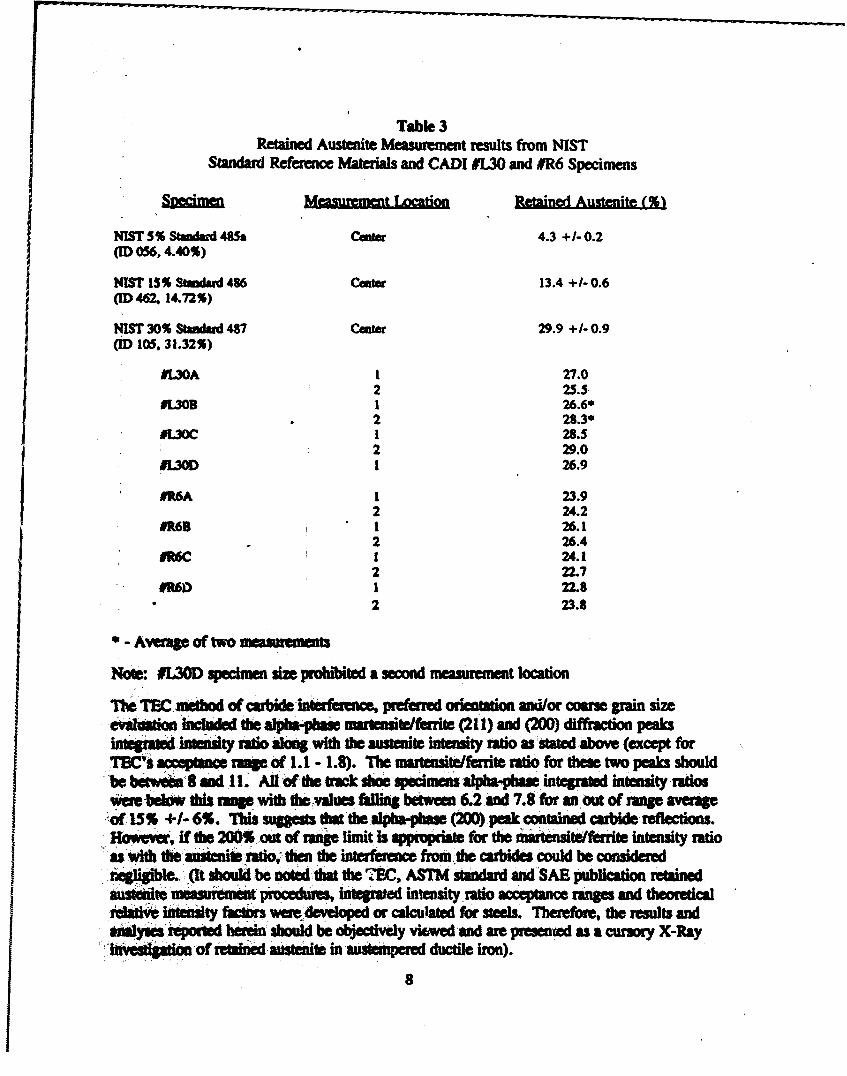
Four specimens from each failed track shoe were sectioned utilizing a water-cooled diamond saw. These samples were denoted as IL30- and #R6- • A" through "D", and were taken from 'similar locations on the track shoes. Standard metallographic grinding and polishing methods were employed in ~_t.rag the Bakelite-mounted specimens for image and X-ray analysis. All retained austenite measuremet!t data were obtained with the TEC Stress Analyzer in the parafocusing configuration, and from the diffraction of chromium K-alpha radiation from the (211) and ('200) crystallographic planes of the alpha-phase martensite/ferrite and the (220) and (200) planes of the gamma-phase austenite. The specimens were irradiated at the surface with an approximate 4mm round spot size at two arbinarily chosen locations and orientations. Four degR:es of psi~on was activated for ~ measurement to circumvent coarse grain effects that could be encountered in this ·:ast material. The Buehler Omnimet n Image Analysis generated a graphite nodule percent area of 11.1 ~ +I- 0.6% (average of four radinp from two each IL30 and IR6 specimens). These results were incorporated in the TBC measurement program as carbide ~tage. National Institute of Standards and Tcclmology (NIST) S, 15 and 30 percent austenite in ferrite standald refemtc:e materials 48Sa, 486 and 487, rapectively, were used as a means of determining X-ray measurement accuracy aod rwpeatabilit.v. Measurements were performed on these standards on three separate occasions.
Table 3 fists ·£be X-ray diffraction retained austenite measurement results. An approximately uniform austenite .volume fraction was determined in both track shoes repnlless of where the specimens were sectioned fmm the track shoes or the X-ray measurement location or orientation. However, the IL30 tdained austenite percentage is somewhat bigber on average tban the IR6 (27.4. compated to 24.3~). Graphi1e nodule c:ontmt, sbrinkap porosity just below tbe X-~ imdiatM surface or sample prepam;.an (temperature or deformation tlanSforminc tile rdained austenite to martensite) could account fOr this difference, but more likely, it can be attributed to a variation in tbe chemic:al composition and possibly the beat trat prOCess from one track sboe to the other. No sipificant preferred cryst8Dopapbic orientation, come pain size nor carbide interference in tbe cliftilctioli pllbm was detected during this X·Ray hmstiption. Referring to SAE Special Publicafion 4S3 [6], RetoiMtl Austenite IJIId Its M~ By X·Ray DljfrtM:tloll, the ratio of the integrated intensities of the austenite gamma-~ (220) and (200) diffraction peaks should be between 1.2 and 1.8. If the ratio is outside this ranee by more than 200", a severe preferted orientation or coarse grain size is pr-=nt in tbe specimen. Almost half of all calculated alpba-phue integrated intensity ratios feJt·witbin the acceptable range, while the remaining ratios were out of range by far less than tbe 200•1imit, averaging 39~ +1- 17~. Additionally, the results of a martensitic/ferritic pbae residual stress measumnellt made with a chromium K-alpba radiation and the mnHqUared psi method utilizblg ten positive 'psi-angleS further indicated tbat neither of these severe .-·etkts existed.! Though pOlishina-induced stress was measured, the ~tal reJathe integrated intensity data, (uniform and avenging 2,147 +/- 61 for all 1ea pd...-) sugesled a random or near random orientation. Smooth, consistent diffracted j)Mt·sbapes, eYidellce of other than a coarse grain structure, were observed throughout the JI"AAf'*' IIJStenite and residual stress data collections. These results were anticipated since '*'iap bave dtde preferred orientation.
7
I I I
Table3 Retained Austenite Measurement results from NIST
Standard Reference Materials and CADIIL30 and IR6 Specimens
Specimen
NIST 5~ 5aadaid 48Sa (ID 056. 4 • ..0,.)
MIST 15,. St1Ddarc1 .. 86 (ID -i62. 14.72.)
~ 3041 Stladud 487 (ID 105, 31.32,.)
•
11.30A
IUOB
IL30D
IR.6A
IR6B
IR6C
1160
Mcasumnent Lnration
l 2 l 2 1 2 I
1 2 1 2 I 2 1 2
* - A'ftl'IIC of two measu1emcnts
Retained Austenite < 5)
4.3 +/-0.2
13.4 +1-0.6
29.9 +1-0.9
27.0 25.5-26.6• 28.3• 28.5 29.0 26.9
23.9 2-'.2 26.1 26.4 2-t.l 22.7 22.8 23.8
Nole: IL30D specimen size prohibited a second measurement location
~ TEC atbod of catbide·ifteerference, prefened orieolatioll lltli/or come pain size eVila.tioa ·iDcludecllhe ~ marasite/fenite (211) aad (200} diffraction peaks ~ iDieDsity ntio aJona• with tbe austenite intensity Dtio as ·stated .lbove (except for TSC's ~·naae of t.t .. t.8). Tbe llllltenSite/ferrice ratio ror these two peaks should 'be betwdli··s aaclll. AU of·tbe net slioe lptdmeal ~. intep'ated intensity ·ratios ~:beld* Ibis .. witb t:beovllues fil1in& beiwfea 6.2 and 7.8 for IJI.out of ranae averaae
.,of 15~ +I- 6". This.._... that the alpba-pbae (200) peak coocained Cllbide reflections. lloMver, if tbe 200S out of raale limit is ippmpliate for the m&ilelllite/fenite intensity ratio
·· u with the"IUitcnite .fatio' dlen the interferalc:e fronube catbides could be c:onsidered . . . ' ' . . . .
. ~le.. _(It should be .-.1 that tbe ?EC, ASTM staDdant ancfSAB publieation retained ~ measutemeiu pRadins, inlepated intensity .ratio accepcance ranaes anc1 theoretic:al ieladVe iftteality factOrs were_developed or calculated for steels. Therefore, tbe results and tJilyaes'leported ... sbould be objectively vi6wed and ue praencd as a cunory X-Ray
· ":11\Qijpl~ of retlilied-ll..ante in ·austemperec~ ductile iron}.
8
Mtdvmical testing was performed on specimens sectioned from each of the failed track slwes. ASTM A 897 specifies tensile property requ.imnents including ultimate tensile strength, 0.2% yield stratgtb and percent elongation. These properties apply only after the austempering heat tR.atment. The same regioo of track shoe was used in the fabrication of specimens from both track shoe IL30 and #R6, u shown schematically in Figures 37 and 38, respectively. In addition, hardness testing, fracture toughness testing and Charpy impact testing were performed. In each case, the largest possible specimens were fabricated. However, due to geometrical restrictions, the tensile, fracture toughness and impact specimens were subsized.
Tensile Testing
Tensile coupons were sectioned as shown in Figure 39, and tested in accordanc:e with ASTM B 8 ['7), Tat Medlod D/ Tension Testing t/" Mdtllllc Mmerla/s (Subslze). 1be results of tensile tesdna are lisiDI in Table 4. Specimens were tested on a 20,()00-lb capacity Instron universal dcaiUmtchanical 1at machine, with a S,OOO..lb load cell. A crosshead speed of O.OS iDcbeslminute was utilized, and a 112 iDch-lOS extensometer was used to measure strain.
1'81e4 Tensile Test Results
Tensile Coupons from Track Shoes 11.30 and #R6 20,0Cl0-lb Instroo Electromechanical Machine
~ IL30A and IL30BJailed 10 meet the specified UTS and elongation requirements fbt~-~ Specimens IL30C and IL30D conformed 10 tbe aovemina speCification for anire -2 With respect to each Of the ~ts. Each specimen sectioned fmm track shoe .:06·~ 10 tbe aovemina specificalion for Grade 3. In praeral, the raults sugested ;;liif:~mens tabricaled from tbe second failed track shoe were higher in strenatb than those -~from the first fai1ecl triJct shOe. Results from track shoe IR6 specimens agreed with
-·:_ ·-'' ', ''
9
those of CADI specimens tested by tbe contractor, in yield stlalgth and UTS. However, the "EL of the IR6 specimens were slightly lower than the contractor results. Note the variability between the specimens sectioned adjacent to each other from track shoe #1.30.
HIJI'dnm T6ting
Although hardness requirements were not specified for this material, hardness testing wu performed for informational purpooes. Table S lists the results of hardness tests perfonned within the tab region of each of ".e four tensile coupons from track shoes 11..30 and #R6, respectively.
SampleiD
Table! Rockwell ·c· Macrohardness Test Resutt3
Tensile Coupons from Track Shoes 11.30 and IR6 Room Temperature
lSOk&fload Diamond PenefDtor
HRC SampleiD HRC
IL30A 32.4 IR6A 37.1 32.$ 31.8 32.2
IU'JB 32.5 32.3 31.9 32.2
IUOC 32.6 32.3 32.3 32.1
11300 31.9 31.6 32.2 m
Aveaea n.2 ASTM A 19"741: 37 .. 7 HltC
37.2 37.6 37.0
llt6B 37.7 37.7 38.0 37.9 37.9 37.5 37.4 36.0
IR6D 36.0 37.0 37.7 n.1 37.3
ASTM A 197*: 37 .. 7 HRC
• '-11lis baftlnesa value for Glide 150110017 CADI is DOt nr-dltory.
1be baniDea Yllues flom IR6 specimens were pater than thole of IL30 specimens by over 8Ye ltoekwell •c• points. At this nmae of banlness, that translates to an approximate 20,000
/Pii iDcreue iD urs (from SI8Mird baniDess COIMIIioa cbatts). This value is consistent with tbo JlllpitDde of iDcNued lb'eftJtb DOled riom IR6 specimens 11 OOmpared to the stn:natb of
, ·1[.30 tpecimeas. It should allo be noted:tbat the values of bardnas from IR6 specimens just .. the ASTM typiC8l harclftess ranp of 37-47 HRC (conwrted from Brinell 341-444), in COfttiUt wilh the results from 11..30 specimens, which fell below this guideline.
10
I Ff'tll:lln Toughnas Tuting
FJ'ICtUJ'e fOUibness coupons were leCtioned u shown in Fipre 39 and tested per ASTM E 813 (8]. Test Method for Jrc, 11M~ of Fnlt:ture Toughness. Tbe tbn:le-point bend "specimens were prec:racbd at 30 Hz. using a 20,000-pound capacity .lnstton servobydraulic test machine. Tbe crack sizes were measured on each side of the specimen and were u follows:
Sample CliCk Sizes (in.) Cycles
IL30A IL30B IR6A IR6B
Side A Side B
0.0518 and 0.0386 0.0500 and 0.0322 0.0517 and 0.0513 0.0546 and 0.0443
1700 2100 2600 1SOO
Tbe specimens were sublequmdy telled 011 tbe 20,000-pouod capiCity lnsbon electromecfllnkal test machine at 0.02 iacb/minute CIOI1head speed. A 0.100 iDch openina crack pp was oolim1 10 Obcaio tbe lold-cact opeain& clisplla:ment plot. ASTM E 399 [9], Tat Jledtodfor PlilM-Snrllra F1'tlt:llft TDIIglultss of M.mc M•riflb MU referenced in analyzina the data. 'The followiaa resales were ~:
Oae cri1erion stata tbat P.,..JPQ IIIUit be .Jess lhlll 1.10. Tbele specimens clicl not meet this Criterion, thus these data are iavl6d, ICCOidin& ID ASTM E 399. The values of~ were found to be as follows:
Tbe Kq wu doubled s~nce·sabidil aped~ (liZ the sile of SlaftdaN specimens) were tested. '11ae resolta are consistent With .IIIOie obtai.-~ oa tpeeimeDI lelred at Benet Laboratories [10] 1ft • tUnU~t etrort. Tbe ·Benet LlbCntories rau~~s f'lllied tmm 16 to 12 arnn.
F'~p~e 40 sbows tbe notcbed and UDDOtcbed specimens wbicb were sectioned from the failed tract shoes and tested in accordaDc:e with ASTM E 23 [11], Test M~tliods for Notc/W. Btlr lmpoct Te#lllg of Meta/Uc Moterillls. Each specimen wu tesled on the 240 ft-lb capacity Salec impact machine. lifts were utilized to maintain proper specimen height within the madrine. 1be results of this testing are listed in Table 6.
Table6 Cbarpy Impact TestiJI& Results
Impact Coupons from Track shoes 11.30 and #R6 240 ft-lb Satec Impact Machine
nahap.ct v IY was cblbled siDce sublbJe specimens (ane-half the sbJe of~ .,edl-.) wen lelled. Tbe UIIDIMCbed specimcas ta1ec1 met tbe rtqUiremalt set forth in ASTM A: fiT/ fbr Glide 150110017 Cbarpy ban tesled 1t 70- +I- 7•F, with tbe exception of Semple IR6D. The rau1ts 6om tr.:t sbae 11.30 tpeeimeas ll'e JUaher iD IUipitude than the ,..... fiom IDck sboe IR6 spfdmeos. 'Ibis c:onelaeei1D the bardDess lnd tensile results, .. si8ce, ·in .-..... a material witb lower stlal&tb llld eloAptioll (more ductile) will have a bipet IIDpiCt resilllnee tban a IIRJa&er (more brittle) malerial.
Jllr ....
Tile CADI trick sboes bid been fabricalled ICCOI'diaa 1D the climensional requiftments of the ·-~-.t. In &ct, .the same eqiaeeriDa drawiDJ was used. Tbe yield and ultinwe ,rrtlf!f~al,dle ~fiecl·lleel foriial alloy AJSI8640 or 87..0, Orlde D, are . . ~ w tbOii .~CADI, Clrlde 175/125/4. Rowt.rc. tbe percent eJonptbl and pen:ent : ......... ciUltw sutilla*lly. '~'he forpd AJSI 8640 or 87.0 alloy Clll expect to ······pil&iat elnftaliloa doe to 20S, and a percent ftlduclion in uea of approximately
12
•
so~: This is much greater than the CADI value of 4-7% elongation (Grades 17S/12S/4 anti · ISO!loon, respectively). This significant lack of ductility would adversely affect the impact resistanre of the CADI in service. Taking this into consideration, it would seem appropriate that a separate design would have to be developed for the CADI material. Otherwise, how else can a fair ~t be made of CADI? '
The new design would need to take into account the appropriate casting gates and risers. The . cross sectional thickness of the new CAD; design would most likely have to be increased at particu1ar areas of higher stress. Evidence substantiating this claim is shown by the cracking of track shoe IR6 which initiated at tbe pound side of the binocular tube section. This region
. did not even conform to ~ engineering drawing of the forged component u required and was found to be dimeosionally under tolerance by approximately 0.022 inch. 1be CADI tract shoes that were analyzed contained several repm where a thick section abruptly transitional in1o a thin one and would have cliffemlt rates of coolin& during casting. This condition caused intemal sbrinbp cavities !0 form which were DOted on the CADI components during mdllloJdpbic examination. Tbesc cavities were reJatively large, encompassing an:as apptoximately 114• x 314•. Overall, the track shoe design {although proven for a forged compooent) may not be favorable with respect to a castina.
· Eadl of tbe failed track sboes was fitted with an ice cleat in service suagesting that an undue · stras coraatratioo may have existed. Craclring was not confined to a specific region (the · track sboe IL30 failure initia~ at the bolt hole on the pound side, while track shoe IR6 CI'ICbd acrms tbe two •binocular tubes-, which may iDdicate a desip problem. 1be deep
· pooves fOund oil the edae of tbe bolt bole of baCk shoe IL30 my have been tluads madrined by mislike. IDirb left by impart Crom the cleat bolt (allowed to rub against this
· area), war caUied by ~en'ice life, or simply. a poor cbamfer. In any case, the marks may · bave elated an undue 111a1 a~IICCDtradoo tbus i.litiadn& failme.
Practopapllic -.lysis maled dill tbe cract CJriaia was loclted at the bolt hole (ground side) on track shoe IL30. Tbe cnct iaililtion site was found to be on the pound side of each binocular tube oa tract sboe IR6. Ductile dimples were observed on areas of the fracture surllce wbich were only ~ after cbemically removina some of the heavy corrosion
. product.
Cbemica1 analysis twealed a hi&h level of silicon in each of the samples invmpted. This could bave been due to • lddition of ferrosmcon, utilized to boost the nodule count durin& p~Qduedoa. A hiper tbla IIOIIIiaal silicon can1ellt is less tban optimal, since the fracture tauaflue•,..,.,.... ~CADI ctec::n.e widl the increae of silicon. In addition, chromium, -· . mol,.,.._. tklftium and copper were all biaber than the specified limits. Althouah the
· ttrlacrious affecls of JUaber levels of the!e eleanans are minimal, it does suaest poor llllftll(«:lala cbemical contlol.
. ~ euminatioa ~ reprat.lltaliYe samples of the failed track shoes maled a ....,._low DOduJe count for Grade 150/10017 CADI. This deficieDcy also tends to affect die mecMnk:al properties of dlis ma&erial. In addition, some of the nodules were •flalced•,
13
I l
I I l j :
. .
whk:b is not an optimal shape. This shape consists of a high surface to volume ratio, which teads to increue die notch sensitivity of die material, while decreasing the fatipe mel impact resistallce. Tbe etched tnd beat tinted structure of the CADI samples resembled the typical suueture of CADI.
Retained austeni~ measurements were perf01med, revealing contents of27.4~ for track shoe IL30 and 24.3" for track sboe IR6. This difference in retained austenite content correlated to tbe difre.eace in streftlth DOted between tbe two shoes.
A ·yarialioo iD mecbanica! properties between both the 11..30 and IR6 samples was noted. The teasat. properties of IL30 specimens were stiptly lower than those of IR6. The UTS of two 11.30 speciiDaiS fell below the ~le criteria, as did the "EL of two 11..30 specimens. Tbe values anaioed for the IL30 G*imens bad a ldatMly 1arJe sprerd, for a supposed bolaatceeous material. Eacb IR6 fleDSiJe specimen oblaiDecl values conformina to the ICCep4lble crilaia of ASTM A 897. MacldllrciDess testiDa (altbcJu&h not Dlllldalory ~flO ASTM A 897) showed dial tract sboe IR6 specimens met tbe minimum ~ wbiJe tmct shoe IL30 specimens fell well below tbe lower limit. Fracture ......... lesd .. showed IR6 could widiSiiDd f'lacbR beaa' dian 11..30 specimens. Both tn\Ct.,. conformed to tbe allowable impact eDeiiJ for UDilOtCbed specimens • . er•·•tgg
< •
Tbe •:Iaabs of~ mdall....-p:al iiMiliplioft conducted Oil two cast austempered ductile irOn T•151 Ml tlak triCk shoes dill were field tested It Fort Greely, Alaska, sugested tbat 1lae fidlwe wasibe JaUlt of poor p11t desip IDCI process control. The ADI material from the hiro .. aldNted a CDIIIiderilble--- ia lllfdwtkll properties. 1bele clifferences were 1101t llbly Cll_. by vadaaioDs ia the ltniCIUie iDd COIDpOiitioa of the castinp before the .O.aeatpcriaa bellllle~~meat. A hiper .._ optiiDII lilicoll content decleued tbe impact ,_.-.,of dae tact shoes. Moreover, tbe CADI tract lboes were fabricated according to die failed ... enaifteeriaa drawiaa· A ..,._CADI c1Jawina should be developed illcOipOnlllaa a dlicbr CRJII tedion to increue impld resisaance. Some section tbicmesses in tbe Nlioa of ends wae CODiidelably below the require:aeats of the forpd component cliaWiaa. Tbe CCHIIbiaed lower duclility IDd il!ll*l resistaDce of CADI compared to the fcqed lleelllld the Vldtad aectioa ~ reduced lbe ~ bearin& capacity of the CADI track shoes.
14
..
BC'£D!Jqmlatjnps
It was not tbe purpose of this failure investiption to dismiss CADI as a viable track shoe •llllferial. Too many exterdal factors unrelated to CADI led to these failures, making it . difficult to blame them Oil dte ma:aial itself, such u:
~ additional Jtress induced by the attached ice cleats,
*The overall design of the track shoe with respect to casting,
-The CADI shoe fabricated to the same dimensions as the forged shoe,
-The dimensional undel1ola'aDce of the CADI shoe in some areas,
•Poor manufacturing techniques (i.e., additional silicon, some flabd nodules) led to sub-par mecllanical properties for track sboe ILJO.
A fairer. aaessment of tbe ue of CADI in this application would occur if each of the above · factors weae lddressed •
. 1be autbors wisb to tbank n-- DewinJ mel Jack Mullin for seed. . and metallograph , . .. ~..,. oruna Y respecti\'ely, Raymond Hinxman and.Kyu Cho for X-Ray Diffraction, Robert Pasternak and
· Kmn Baney for medwrictl ersaina, and Jolm ICeouP for valuable processing information. Wit6 tbe ~ of lc:ibli Xeot..,, who repraeats Applied Process Inc., each are employed
. by tbe U.S. Army Raearch Laboratory, Watatown, Massachusetts.
1.5
l
Rcfermco
l. Moth, B.W., Abbrevloted Tm Rqonfor the Preproduction QualijictJtion Test (PPQTJ of Product lmprovmu!ntsfor the MJAJ Tank SystDn, U.S. Cold Regions Test Center, Unit 4S818, APO AP 96S08-78SO, USATECOM Project No. 1-VC-oBO-lAl-152, May 1992.
2. Sp«ijictllionfor Austmrpertd Ductile Iron CAstings, ASTM A 897, Volume 01.02, FerroiJs Castings; Ferroalloys.
3. Mdhodfor Ewlluating 1M MiC1'0Sl111C1111' of Graphite in Iron Castings, ASTM A 247, Volume 01.02, Ferrous Cast.inp; Ferroalloys.
4. ICoYacs, B.V., Sr., Het111lnting of ADI Mlcrostructllla. Atmosphere Furnace Company-Technical Center, Uwnia, Mississippi.
S. X-ray Dttemrbttltioll of RettdMd ~ ill St«l willa N«u Rllndom ~c Orimtlltloll, ASTM E 97S, Volume 03.01, Metals-Mechanical Testin&; Elevated mel Low-Temperatule Tests; Metallography.
6. SAB Special Publication 4S3, RettliN!d Austelllle ll1ld Its Measumnents by X-ray • Dlflroctiola.
7. Test M«hods oj'TettSloll Tatlllg oj'Mellllllc Materillls, ASTM E 8, Volume 03.01, MecaJ.MecEcal Teldna; EleYated IJid Low-Tempcnture Tests; Melallography.
8. Test M«hodfor J., a II~ of F1rlrctlur TDIIglrnm, ASTM E 813, Volume 03.01, Mecals-Mecbanical Testing; Elevated and Low-Temperature Tests; Metallography.
9. Test Methodjbr l'lt.IM-Strtdll Frtlt:tuiY Touglutal 0/MettJlllc Materials, ASTM E 399, Volume 03.01, Mefals-Mecbanical Testing; Elevated and Low-Temperature Tests;
' Mclallo&raPbY-
10. Fracture Toualmess Indicators for ADI, Benet Laboratories.
11. Tat lldlolbjbr Notdted Btlr lnlpoa Teltbll 0/Mitlllllc Mattriols, ASTM B 23, Voluaie 03.01, lfet:U.Mechlnnt Testina; Blevated and Low-Temperature Tests; MetallOppby. .
16
FIGURE 1 Fai 1ed track. shoe #I,30 in the as received condition. Reduced 80 %
FIGURE 2 Failed track shoe #R6 in the as-received condition. Reduced 80%
17
OOJ004 I’ a
FIGURE 3 Schematic showing dimensions of the CAD1 track shoes.
.
FIGURE 4 Schematic showing regions of dimensional inspection for each of the failed trackshoes.
18
FIGURE 5 Macrograph showing area of minimum thickness on the binocular tube of trackshoe #R6. Mag. 10x. (Scale in millimeters).
FIGURE 6 Macrograph showing thickness of the #R6 binocular tube on the ground side.Mag. 10x. (Scale in millimeters).
FIGURE 19 End view of track shoe #R6 showing cracking. Reduced 60%
FIGURE 20
_-----s-------
----Lo_&-----_
-.
F-7 ZP
___-------l-----.
)
____l-_-----s-l--
Fs-~_____-------w-v--
----
SectionedRegion
Schematic showing method of sectioning for the fracture surfaces of track shoe#R6.
27
t-J 00
Figure 2 Photo montage showing fracture faces A and C. Arrow indicates fracture origin, as highlighted by chevron patterns and river markings. Mag. 2x.
Figure 22 Photo montage showing fracture faces B and D. Arrow indicates fracture origin, as highlighted by chevron patterns and river markings. Mag. 2x.
.
tsIi
!
i
Origin
FIGURE 23 Fracture origin of fracture face A, of track shoe #R6. Mag. 7.5x.
Origin
FIGURE 24 Fracture origin of fracture face B, of track shoe #R6. Mag. 7.5x
30
FIGURE 25 SEM of corroded fracture surface showing prevalent “mud-cracking”. Mag.2500x.
FIGURE 26 SEM showing representative morphology of a less corroded region of thefracture surfaces. Mag . 500x.
31
FIGURE 27 SEM showing area of ductile dimples suggesting overload failure. Mag. 2000x.
FIGURE 28 SEM of another area of ductile dimples noted on a less corroded region of thefracture surfaces. Mag. 2000x. .
32
FIGURE 29 Low magnification SEM photograph of the fracture surface of a laboratorytested impact specimen. Mag. 150x.
FIGURE 30 High magnification SEM photograph of the fracture surface of a laboratorytested impact specimen. Note the ductile dimples, similar to those found on thefracture surface of the failed track shoes. Mag. 800x.
33
crack origin
shrinkage cavity
FIGURE 3 1 Schematic of sectioning diagram for metallographic and retained austenitesamples from track shoe #L30. Similar specimens were sectioned from trackshoe #R6.
FIGURE 32 Large shrinkage cavity noted on track shoe #L30 metallographic specimen.Mag. 12.5x.
34
FIGURE 33 As-polished representative microstructure of a CAD1 sample, showing thegraphite nodules. Nodule count was determined to be 132 per sq. mm., whilenodule size was approximately 5 to 6, according to ASTM A 247. Mag. 100x.
FIGURE 34 Typical microstructure of track shoe CADI with the application of a 4% Picral‘etchant. Mag. 500x.
35
FIGURE 35 Typical structure of CAD1 when polished, etched with 4% Picral and heat tintedat 50CbF for 4 hours. Mag. 100x.
FIGURE 36 Higher magnification of structure of CADI when polished, etched with 4%Picral and heat tinted at 5OOoF for 4 hours. Mag. 1000x.
36
‘_Fracture Face A
bolt holes
Fracture Face C
T = Tensile FT = Fracture ToughnessNC =Notched Charpy ImpactUN = Unnotched Charpy Impact


![Austempered Ductile Iron [Adi]1](https://static.documents.pub/doc/80x56/55332f154a79592c4f8b4800/austempered-ductile-iron-adi1.jpg)


