20
Moving Metrology into the 21st Century Form TalySurf Series 2 A unique concept in form and surface measurement

�
Moving Metrology into the 21st Century
Form TalySurf Series 2A unique concept in form and
surface measurement

2
FORM TALYSURF SERIES 2:Setting new standards for Form and
Since its launch in 1989, the innovative Form TalysurfSeries has dominated the world market for form and
surface texture measurement. Nevertheless, our constantdrive for advanced accuracy, speed and software capabilityhas led to the introduction of Form Talysurf Series 2,incorporating µltra Windows NTTM software.
Flexible By DesignForm Talysurf Series 2 has been designed to meet the varied andchanging needs of industry. A choice of traverse units, softwareand accessories allow high precision surface finish and form measurements to be made on small, large or complex components,for laboratory design analysis or production batch measurements.
Form Talysurf Series 2 can offer complete flexibility for use inthe following ways:
● Simultaneous form and surface finishmeasurement
● User customisable interface
● Programmed, automated batch measurement
● On screen comparison to “master”component data
● Non contact measurement for delicatesurfaces
● Three dimensional measurements within-depth analysis and reporting
● Measurement and analysis of aspherical or conical components
● Advanced contour analysis
Revolutionary PrecisionThe nanometric resolution throughout its10mm (0.4in) gauge range makes the PGIthe most powerful gauging system availableon any form and surface texture instrument.
The µltra software menus are structured in a logical, easy to understand sequence.
A significant benefit of Form Talysurf Series 2 is systemprogrammability which enables measurement in X, Y and Z axis(Y axis optional), analysis and results output to be madeautomatically, without operator intervention.
The unique wide gauge range/high resolution of Form TalysurfSeries 2 allows highly accurate, simultaneous form, waviness andsurface measurement of components.
Now with µltra Windows NTTM software
3
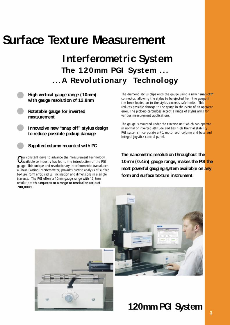
High vertical gauge range (10mm)with gauge resolution of 12.8nm
Rotatable gauge for invertedmeasurement
Innovative new “snap off” stylus design to reduce possible pickup damage
Supplied column mounted with PC
Our constant drive to advance the measurement technologyavailable to industry has led to the introduction of the PGI
gauge. This unique and revolutionary interferometric transducer,a Phase Grating Interferometer, provides precise analysis of surfacetexture, form error, radius, inclination and dimensions in a singletraverse. The PGI offers a 10mm gauge range with 12.8nmresolution: this equates to a range to resolution ratio of780,000:1.
Interferometric System
The diamond stylus clips onto the gauge using a new “snap off”connector, allowing the stylus to be ejected from the gauge ifthe force loaded on to the stylus exceeds safe limits. Thisreduces possible damage to the gauge in the event of an operatorerror. The pick-up cartridges accept a range of stylus arms forvarious measurement applications.
The gauge is mounted under the traverse unit which can operatein normal or inverted attitude and has high thermal stability.PGI systems incorporate a PC, motorised column and base andintegral joystick control panel.
The nanometric resolution throughout the10mm (0.4in) gauge range, makes the PGI themost powerful gauging system available on anyform and surface texture instrument.
The 120mm PGI System . . .. . .A Revolut ionary Technology
120mm PGI System3
Surface Texture Measurement

120mm Traverse Unit
4
● High accuracy straightness
● Free standing or column mounted
● Absolute positional control
● 1mm gauge range with 16nm resolution0.04mm gauge range with 0.6nm resolution
● 50mm or 120mm traverse units
FORM TALYSURF SERIES 2: Inductive Systems
The versatile inductive traverse units offer high accuracystraightness over their traverse length, having absolute positional
control throughout their traverse length, with fixed optical endstops at the limit of travel in either direction. Software endstops are programmable so that the user can artificially limit thetraverse movement.
The inductive traverse units may be used free standing or column mounted, in conjunction with a high specification DellPC. They can be used in automatic programmable or manualmode, or using an optional remote hand held controller.
Inductive Pick-up options, for maximum flexibility
50mm Traverse Unit
STANDARD INDUCTIVE PICK-UP Code 112/2564The inductive pick-up has a pivoted and balanced beam for anyattitude use with 1mm (0.039in) range styli. A range of interchangeable styli and skids is available (see page 14 ).
WIDE RANGE PICK-UP Code 112/2628The wide range inductive pick-up has a measuring range of28mm (1.10in) and can detect form errors of less than 15µm(600µin). Available as a plug-in accessory for the 50mm and120mm inductive units, it can be used in either column mountedor free standing systems. The wide range pick-up is suppliedwith 3 interchangeable stylus arms.
Resolution: 426nm (17µin)
NON-CONTACT GAUGE Code B112/2671Comprising a focus follower measuring head with a programmablecontroller for fast, simple set-up, the non-contact gauge can beused in place of inductive pick-ups for analysis of more sensitivecomponents, such as:
● Soft and touch sensitive surfaces such as printing pastes and coatings
● Wet or dry solder pastes and printed conductive pastes● Contact and intraocular ophthalmic lenses
Range/Resolution: ±500µm/140nm± 50µm/20nm
The most economical of the Form Talysurf Series 2 options, the50mm Traverse Unit can be used either free standing or columnmounted. The inductive gauge is mounted to an independentvertical height adjustment arrangement, which also enables thegauge to operate with or without a skid nosepiece.
The 120mm Traverse Unit is ideal for longer measurements orwhere contour type measurement is required: when used with amotorised column it can accommodate the wide range pick-upaccessory for profile measurement. This traverse unit can also beused in free standing mode.
The inductive gauge is mounted to the traverse unit on a hingedpick-up stem, allowing the gauge to be used with or without askid nosepiece. Used skidless, the gauge can be inverted to measure the underside of a surface.
Non-Contact Gauge
Wide Range Pick-up
Right Angle Attachment (SKID) Code 112/2040 orRight Angle Attachment (SKIDLESS) Code 112/2022
A right angle measurement accessory is available which supports the pick-up at right angles for measuring betweenshoulders on components such as crankshafts.

5
COLUMN OPTIONS
This epoxy granite, motorised column gives fully motorisedup/down and tilt movement, offering a rigid, stable base forprecise measurement. Two heights are available to give 450mm(17.7in) or 700mm (27.5in) vertical traverse.
Both columns have a servo controlled motor drive and encoderto ensure absolute positional control. In addition, amanual/motorised tilt control is provided to allow the traverseunit to be adjusted (under computer control if required)parallel to the component being measured, thus reducing operatorsetup times. An adapter plate is available to extend the rangeof traverse tilt to 45 degrees in 15 degree increments.
Motorised column mounted configurations of Form TalysurfSeries 2 allow automatic stylus “stop on contact” with the workpiece,centred in the gauge range, enabling automatic “hands off”measurement of components.
The epoxy granite base has two integral tee slots for mountingworkholding accessories, the slots being parallel within 0.3mm(0.012in).
For use with the 50mm and 120mm inductive traverse units, toprovide a cost effective alternative to the motorised columnand base.
The 50mm and 120mm traverse units (inductive systems) can beused free standing by the use of brackets, for the measurementof flat and arcuate surfaces.
Motorised Column & Base
Free Standing Brackets & Tilt Micrometers
Manual Column & Base

The Form Talysurf Series 2 PGI system comprises:
● Traverse unit ● Pick-up ● Electronic Interface Unit ● Motorised Column & Granite Base● Deskjet printer ● PC Form and Surface Texture Analysis Software
6
FORM TALYSURF SERIES 2:Flexible Configuration to meet your changing needs
0
0 1 2
10 20 30 40 50
112/2564-417
112/2564-431
0
0 1 2 3 4 inch
10 20 30 40 50 60 70 80 90 100 110 120mm
PGI SYSTEM
Optional Motorised or Manual Column
INDUCTIVE OPTIONS
CHOOSE
50mm Traverse Unit- shown in free standing mode
120mm Traverse Unit- shown in free standing mode
112/2564-431
Wide Range Pick-up code 112/2628
Non-Contact Gauge code B112/2671
Inductive Pick-up code 112/2564

7
COMPUTER OPTIONS
High specification Dell desktop PCs are supplied as standardwith all Form Talysurf Series instrument systems. µltra WindowsNTTM software, together with any additional modules, are pre-installed and tested at our Leicester head office.
Please refer to your Taylor Hobson representative for the latest specification and details of Dell’s worldwide customer support at the time of purchase.
PrintersAn HP 895 CXi colour inkjet printer is supplied as standard withPGI systems and is optional with inductive. This allows fulladvantage to be taken of the colour output from µltra, Talymapand Contour software. The systems are also compatible with anoptional laser printer.
PC
+ 5.0um
+ 4.0um
+ 3.0um
+ 2.0um
+ 1.0um
+ 0.0um
- 1.0um
- 2.0um
- 3.0um
- 4.0um
- 5.0um
+ 5.0um
+ 4.0um
+ 3.0um
+ 2.0um
+ 1.0um
+ 0.0um
- 1.0um
- 2.0um
- 3.0um
- 4.0um
- 5.0um
0
0 1 2 3
10 20 30 40 50 60 70 80 90 1
8
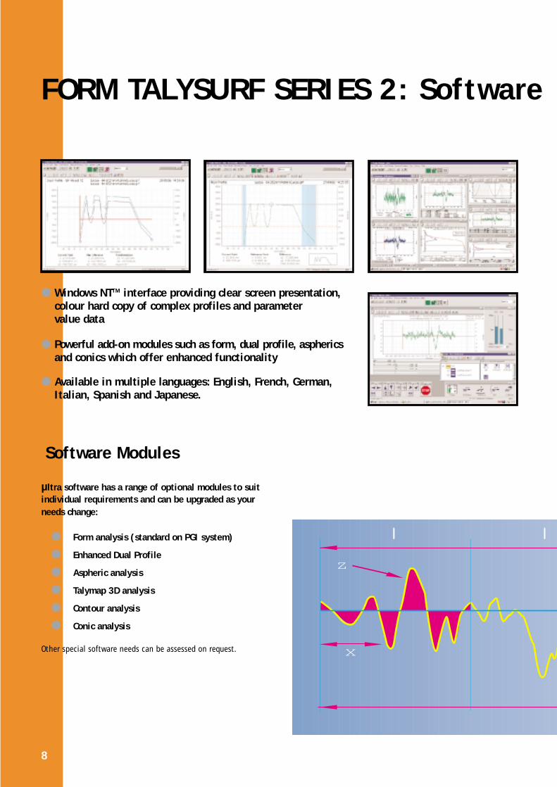
FORM TALYSURF SERIES 2: Software
µltra software has a range of optional modules to suitindividual requirements and can be upgraded as yourneeds change:
● Form analysis (standard on PGI system)
● Enhanced Dual Profile
● Aspheric analysis
● Talymap 3D analysis
● Contour analysis
● Conic analysis
Other special software needs can be assessed on request.
Z
X
Software Modules
● Windows NTTM interface providing clear screen presentation,colour hard copy of complex profiles and parameter value data
● Powerful add-on modules such as form, dual profile, asphericsand conics which offer enhanced functionality
● Available in multiple languages: English, French, German, Italian, Spanish and Japanese.

9
Primary parameters: Pa, Pc, Pda, Pdc, Pdq, PHSC, Pku,Pln, PLo, Plq, Pmr(c), Pp, PPc, Pq, PS, Psk, PSm, Pt, Pv,PVo, Pz, Pz(JIS) Roughness parameters: R3y, R3z, Ra, Rc, Rda, Rdc, Rdq, RHSC,Rku, Rln, RLo, Rlq, Rmr, Rmr(c), Rp, RPc, Rq, RS, Rsk, RSm, Rt,Rv, RVo, Rz, Rz(JIS)Waviness Parameters: Wa, Wc, Wda, Wdc, Wdq, WHSc, Wku,Wln, WLo, Wlq, Wmr, Wmr(c), Wp, WPc, Wq, WS, Wsk, WSm, Wt,Wv, WVo, WzR+W Parameters: Ar, Aw, Pt, R, Rx, Sar, Saw, Sr, Sw, W, Wte, WxRk Parameters: A1, A2, Mr1, Mr2, Rk, Rpk, RvkAspheric Parameters(optional with 112/2845): Fig, Ra, Rt,Smn, Smx, Tilt, Xp, Xt, Xv
Where applicable, the above parameters conform toand are named as per ISO standards 13565-1-2, 4287-1997 and 12085.
Options for µltra FTSS112/2842 -01 - Base µltra software112/2843 -01 - Surface Finish Form112/2844 -01 - Surface Finish Conics112/2845 -01 - Surface Finish Aspherics112/2846 -01 - Surface Finish Dual Profile
L
Form Analysis SoftwareSurface Finish Parameters
Form Analysis Software Code 112/2845-01
In addition to the full range of surface texture parameters,this module provides:
Form error: calculated with reference to a best fit concave orconvex circular arc or straight line, including all surfaceroughness detail. Alternatively with reference to a minimumzone (which is the minimum separation between two parallellines containing the data set).
Radius: using a least squares best fit, concave or convexcircular arcs, can be automatically calculated from selecteddata. The option to exclude unwanted surface features such asedges is also available. Alternatively, the absolute radius can beset to analyse the actual deviation from a design master. Othercalculated parameters include the centre co-ordinate and pitch.
Angle: using a straight line or minimum zone algorithm,surface tilt can be determined and removed prior to parameteranalysis. Other calculated values include intercept and pitch.
Dimension: the linear relationship of surface features can beassessed and compared, due to the ability to calculate true Xand Z co-ordinate positions.
The above is standard on PGI systems and optional on Inductive.
Full explanations of the parameters listed are available in our Parameter Booklet - please ask your area representative for a copy.
n

Angle
0.832
2.934
55.916
9.741
Radius
Height
Contour Software Analysis Code 112/2867-01
10
COMPREHENSIVE RANGE OF SOFTWARE:
Analysis of contour measurement features such asradii, angles, length and height, is available usingTaylor Hobson’s new Windows NTTM based Contour software which is fully compatible with µltra.
Features include:
Measurement Macros: These can be learnt and edited to formuser programs for repeat measurement routines, cutting downrepetitive operator input; execution of programs is via a seriesof definable “fastkeys”.
Individual feature tolerancing: Individual sections of themeasurement template can be toleranced with varying values -for example a wide tolerance on a flat area of a surface andtighter tolerances on radii.
Comparison of DXF files to contour: When measuring aknown contour, “best fit” individual geometric elements arecalculated with reference to a template and the comparison of eachpoint in the contour against the nearest element in the template.
Geometric element fit to unknown contour: When measuringcomponents of an unknown contour, the software finds geometricelements that best suit the profile and determines the size, positionand relationship between profile features, plus other functions.

Aspherical Form: Assessments of form error, surface slope errorand tilt in comparison with operator defined design data, in theform of a polynomial expression.
Provides major and minor axes values and tilt, and residual surface texture analysis after removal of best fit elliptical orhyperbolic forms.
The surface geometry of complex asymmetrical components canbe analysed with the Dual Profile facility. This program allowsthe measurement profile of a master shape or prototype componentto be saved as a template. Subsequent components can bemeasured and simultaneously displayed with the template datafor immediate comparison.
Conical Form Software Code 112/2844-01
to suit multiple applications
Aspheric Form Software Code 112/2845-01
CimworksTM SPC
Dual ProfileCode 112/2846-01
Aspheric Form Software
11
Taylor Hobson, through partnership with Cimworks of the US,offer a range of market leading Cimworks SPC software solutions.These are fully compatible with µltra. Please contact your TaylorHobson representative for details of the most suitable productfor your application.
Conical Form Software
Dual Profile Software

12
3D TOPOGRAPHY MEASUREMENT
Data for 3D analysis is collected by data logging a number of parallel profiles at a pre-determined trace length and spacing,using the translation stage below.
Translation Stage Code 112/2635A Y-axis stage, motor driven to ensure accurate sample spacingfor data logging parallel profiles of a component. (1µm step resolution over 50mm total movement). The stage can be locatedin the tee slots of the Form Talysurf epoxy base.
Control of absolute position, relative position and continuousmovement is achieved through software and an external controller.
Inclination Stage Code 112/2275An optional inclination stage to provide precisely controlledtilt, used with the translation stage (112/2635).
Talymap Software Talymap Basic B112/2818, ExpertB112/2819 & Universal B112/2820.
Talymap software allows a 3D surface to be viewed in a variety ofways to identify particular surface features. For example:
● Axonometric projection ● Wear simulation
● Colour height representation ● Form removal
Added features include zoom, truncation, dimensional measurementin X, Y and Z axes, view angle and rotation, single trace plot/zoom,least squares plane option, form removal for cylinder, sphere andpolynomial and profile inversion, displayed in monochrome orfull colour. Desk Top Publishing facilities allow comprehensivemeasurement reports to be created. For full details please requesta copy of our Talymap brochure.
Talymap 3D Topography Software
3D Topography Measurement 3D Surface Texture CharacterisationTaylor Hobson is totally committed to the development of 3Dsurface texture characterisation. There are currently no definitiveinternational standards, therefore Taylor Hobson is activelyinvolved in the ISO project for 3D parameters and researchwhich will lead to definitive international standards.
Three Line Calibration Standard Code 112/964.A three line step height calibration standard can be supplied with any Form Talysurf Series 2 traverse unit for calibration when surface texture only is to be analysed.
80mm (3.15in) Radius Calibration StandardCode 112/2028For a 120mm system using either the PGI gauge or wide range pick-up, the 80mm (3.15in) radius calibration standard is an essential accessory.
13
CALIBRATION STANDARDS
Advanced Calibration Techniques for optimum system repeatability
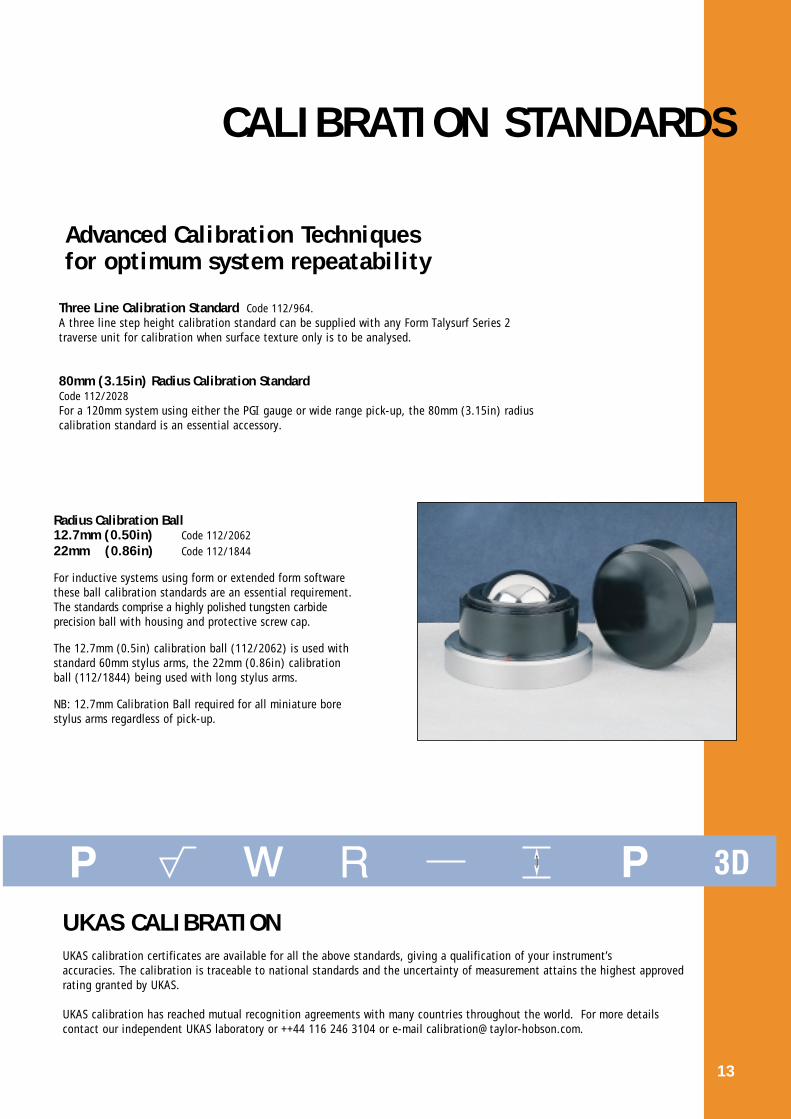
Radius Calibration Ball12.7mm (0.50in) Code 112/206222mm (0.86in) Code 112/1844
For inductive systems using form or extended form softwarethese ball calibration standards are an essential requirement.The standards comprise a highly polished tungsten carbide precision ball with housing and protective screw cap.
The 12.7mm (0.5in) calibration ball (112/2062) is used withstandard 60mm stylus arms, the 22mm (0.86in) calibrationball (112/1844) being used with long stylus arms.
NB: 12.7mm Calibration Ball required for all miniature bore stylus arms regardless of pick-up.
UKAS CALIBRATIONUKAS calibration certificates are available for all the above standards, giving a qualification of your instrument’saccuracies. The calibration is traceable to national standards and the uncertainty of measurement attains the highest approved rating granted by UKAS.
UKAS calibration has reached mutual recognition agreements with many countries throughout the world. For more details contact our independent UKAS laboratory or ++44 116 246 3104 or e-mail [email protected].

All stylus arms have 90˚ conisphere diamond styli with2µm nominal radius tips unless otherwise stated.
The following styli are suitable for the inductive pick-upCode 112/2564 and 112/2008.
Standard Stylus Arm Code 112/2009Nominal range 1mm (0.039in)
Ball Stylus Arm Code 112/2010Nominal range 2mm (0.078in) for form measurement500µm radius sapphire ball stylus
Recess Stylus Arm Code 112/2011Nominal range 1mm (0.039in)
Small Bore Stylus Arm Code 112/2012Nominal range 1mm (0.039in)
Chisel Edge Stylus Arm Code 112/2013Nominal range 1mm (0.039in)2µm x 750µm chisel diamond stylus
All 60mm length styli can be specified with the appropriateskid or nosepiece. A shoe nosepiece may be specified for surfacemeasurement when the cut-offs used are greater than 0.8mm(0.031in).
120mm length styli must be used skidless.
For the 120mm traverse unit, a hinged pick-up stem is available(112/2014) for both skid and skidless use. Alternatively asolid pick-up stem (112/2015, supplied as standard on 120mmcolumn mounted system) may be specified for maximummeasurement loop rigidity when higher accuracies are required(skidless use only).
14
S T Y L U S O P T I O N S
A wide choice of pick-ups, styli, workholding accessoriesand furniture is available. If our standard accessories donot fit your requirement, our Applications Department willcustomise accessories to solve your measurement problem.
Stylus Stop Attachment Code 112/2098 Inductive, 112/2701 PGIFor use when measuring interrupted surfaces, this attachmentstops the stylus falling too far into the surface interrupt,thus preventing tip damage when it recontacts the surface whiletraversing.
I n d u c t i ve Stylus Arms
57.5
8.3mm
117.5mm
16.5mm
57.5mm
14.7mm
57.5mm
1.2mm
57.5mm
9.0mm

15
PGI Stylus Arms
The following styli are available for use with the PGI pick-up/traverse unit Code 112/2563
60˚ Standard Conisphere Stylus Arm Code 112/2689Nominal range 10mm (0.4in)
Ball Stylus Arm Code 112/2620120mm, nominal range 20mm (0.8in)
Ball Stylus Arm Code 112/2621150mm, nominal range 25mm (0.98in)
Both 500µm sapphire ball styli
Small Bore Stylus Arm Code 112/2622Nominal range 10mm (0.4in)
Miniature Bore Stylus Arm Code 112/2623Nominal range 10mm (0.4in)
Recess Stylus Arm Code 112/2624Nominal range 10mm (0.4in)
Right Angle Stylus Arm Code 112/2625Nominal range 10mm (0.4in)
Right Angle Rear Facing Stylus ArmCode 112/2626Nominal range 10mm (0.4in)
60.0mm
14.5mm
112/2620 - 120mm112/2621 - 150mm
112/2620 - 27.8mm112/2621 - 32.5mm
60.0mm
1.9mm
60.0mm
1.2mm
60.0mm
28.7mm
60.0mm
13.4mm
60.0mm
13.8mm
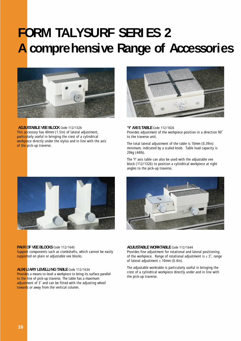
‘Y’ AXIS TABLE Code 112/1826Provides adjustment of the workpiece position in a direction 90˚to the traverse unit.
The total lateral adjustment of the table is 10mm (0.39in)minimum, indicated by a scaled knob. Table load capacity is20kg (44lb).
The ‘Y’ axis table can also be used with the adjustable veeblock (112/1326) to position a cylindrical workpiece at rightangles to the pick-up traverse.
ADJUSTABLE WORKTABLE Code 112/1644Provides fine adjustment for rotational and lateral positioningof the workpiece. Range of rotational adjustment is ± 3˚, rangeof lateral adjustment ± 10mm (0.4in).
The adjustable worktable is particularly useful in bringing thecrest of a cylindrical workpiece directly under and in line withthe pick-up traverse.
16
FORM TALYSURF SERIES 2 A comprehensive Range of Accessories
ADJUSTABLE VEE BLOCK Code 112/1326This accessory has 40mm (1.5in) of lateral adjustment,particularly useful in bringing the crest of a cylindricalworkpiece directly under the stylus and in line with the axis of the pick-up traverse.
PAIR OF VEE BLOCKS Code 112/1645Support components such as crankshafts, which cannot be easilysupported on plain or adjustable vee blocks.
AUXILIARY LEVELLING TABLE Code 112/1634Provides a means to level a workpiece to bring its surface parallelto the line of pick-up traverse. The table has a maximum adjustment of 3˚ and can be fitted with the adjusting wheeltowards or away from the vertical column.

17
UNIVERSAL WORKTABLE (Modular Construction)From the selection of components listed below a universalworktable incorporating X, Y and Z axes, rotary stage, tiltingstage and vee block can be configured.
The Universal Tables versatility can save time in setting upcomponents, in addition to having a large range of measuringapplications.
Components: (from top to bottom of illustration)
Vee Plates Code 112/2220
Simple Rotary Stage Code 112/2219
Graduated Rotary Stage Code 112/2218360˚ of movement, graduated in degrees with 5˚ of fine movement, graduated to ±0.5˚.
Tilting Worktable Code 112/2214The worktable can be manually moved in 2 planes at 90˚, with a range of 2.5˚.
25mm (1in) Linear Stage Code 112/2216To achieve orthogonal X and Y axis traverse use 2 linearstages.
Adapter Plate for 25mm (1in) Linear StageCode 112/2217
Location Dowels Code 112/2215
EYEPIECESUsed to facilitate the positioning of small workpieces relativeto the stylus during set-up.
X25 Eyepiece: Code 112/2194X10 Eyepiece: Code 112/2193Microscope Tube for the Eyepiece: Code 112/2192Microscope Stand for the Tube: Code 112/2190
A Camera with monitor can be specified as a special application.
TRAVERSE UNIT TILT ATTACHMENTCode 112/2060This provides 0, +15, +30 and +45˚ positions and in conjunctionwith the motorised tilt enables the traverse unit to be tilted -9˚to +54˚. (For use with inductive systems only).
REPLICA KIT Code 112/727Contains prepared quantities of materials for producing replicas ofworkpiece surfaces inaccessible for direct stylus measurement.The inherent surface texture of the replica material has an Ra ofabout 0.1µm (4µin). It is limited to surfaces having an Ragreater than 0.2µm (8µin). It is not possible to measure trueform with the kit.
ENVIRONMENTAL CABINET Code K510/944For additional protection against ambient conditions anenvironmental cabinet is available. Cabinets may also bespecified for the processing systems.
FURNITUREA range of instrument and accessory desks is available to holdthe Form Talysurf Series, computer and related items.

PGI
Traverse Length 120mm (4.72in)Traverse Speed 10mm/sec (0.39in/sec) maximumMeasuring Speeds 1mm and 0.5mm/sec ±5%
(0.04in and 0.02in/sec)Return Speed up to 5mm/sec (0.2in/sec)
Gauge Type Phase Grating Interferometer, 1mN (100mg)force nominal
Measuring Range 10mm (0.39in)Resolution 12.8nm @ 10mm range
(0.5µin @ 0.39in range)
Range to Resolution Ratio 780,000:1Straightness Accuracy 0.5µm over 120mm traverse
(20µin over 4.72in)0.2µm over any 20mm traverse(8µin over any 0.78in)
Data Resolution 0.25µm (10µin)Dimensions (LxDxH) 396 x 127 x 195mm (15.6 x 5 x 7.7in)Weight 11.5kg (23.3lb)
TRAVERSE UNIT ACCURACIES
SKIDLESS 10mm (0.39in) range:(other stylus arms are available with extended range)
SURFACE TEXTUREParameters 2% ±4nm(0.16µin) (peak parameters only)
FORMTo best fit straight line (P+V) 0.5µm over 120mm (20µin over 4.7in)
0.25µm over 60mm (10µin over 2.3in)0.2µm over 20mm (8µin over 0.78in)
To best fit circular arc (P+V) 0.2µm over 20mm (8µin over 0.78in)
INCLINATION Over centre 8mm (0.31in) rangeTo best fit straight lineRange ±35˚Accuracy less than 0.5 arc mins
RADIUS Over centre 8mm (0.31in) range:0.1 to 12.5mm (0.004 to 0.5in) 1 to 0.02% of nominal12.5 to 25mm (0.5 to 1.0in) 0.02% of nominal25 to 1000mm (1.0 to 40in) 0.02 to 1% of nominal 1000 to 2000mm (40 to 80in) 0.1% of nominal
18
SPECIFICATION T E C H N I C

50mm Inductive 120mm Inductive
Traverse Length 50mm (1.97in) 120mm (4.72in)Traverse Speed 10mm/sec (0.39in/sec) maximum 10mm/sec (0.39in/sec) maximumMeasuring Speeds 1mm and 0.5mm/sec ±5% 1mm and 0.5mm/sec ±5%
(0.04in and 0.02in/sec) (0.04in and 0.02in/sec)Return Speed up to 5mm/sec up to 5mm/sec
(0.2in/sec) (0.02in/sec)
Gauge Type Inductive, 1mN (100mg) force nominal Inductive, 1mN (100mg) force nominalMeasuring Range 1mm (0.039in) 1mm (0.039in)Resolution 16nm @ 1mm range 16nm @ 1mm range
(0.64µin @ 0.039in range) (0.64µin @ 0.039in range)3nm @ 0.2mm range 3nm @ 0.2mm range(0.12µin @ 0.008in range) (0.12µin @ 0.008in range)0.6nm @ 0.04mm range 0.6nm @ 0.04mm range(0.024µin @ 0.0016in) (0.024µin @ 0.0016in range)
Range to Resolution Ratio 65,536:1 65,536:1Straightness Accuracy - column mounted 0.4µm over 50mm traverse 0.5µm over 120mm traverse
(16µin over 1.97in) (20µin over 4.72in)0.2µm over any 20mm traverse 0.2µm over any 20mm traverse (8µin over any 0.78in) (8µin over any 0.78in)
free standing 0.4µm over 50mm traverse 1µm over 120mm traverse(16µm over 1.97in) (40µin/4.72in)0.12µm over any 20mm traverse 0.3µm over any 20mm traverse(8µin over any 20mm traverse) (12µin/0.78in)
Data Resolution 0.25µm (10µin) 0.25µm (10µin)Dimensions (LxDxH) 374 x 114 x 125mm (14.7 x 4.5 x 4.9in) 396 x 127 x 195mm (15.6 x 5 x 7.7in)Weight 7kg (15.4lb) 11.5kg (25.3lb)
TRAVERSE UNIT ACCURACIESSKIDLESS 1mm (0.039in) range: 1mm (0.39in) range:
other stylus arms are available with extended range other stlus arms are available with extended range
SURFACE TEXTUREParameters 2% ±4nm(0.16µin) (peak parameters only) 2% ±4nm(0.16µin) (peak parameters only) FORMTo best fit straight line 0.4µm over 50mm (16µin over 1.97in) 0.5µm over 120mm (20µin over 4.7in)(P+V) 0.2µm over 20mm (8µin over0.78in) 0.25µm over 60mm (10µin over 2.3in)
0.2µm over 20mm (8µin over 0.78in)
To best fit circular arc 0.2µm over 9.5mm 0.2µm over 9.5mm (p+v) (8µin over 0.37in) (8µin over 0.37in)
INCLINATIONTo best fit straight lineRange ±35˚ ±35˚Accuracy less than 0.5 arc mins less than 0.5 arc minsthan 0.5 arc minsRADIUS0.1 to 12.5mm (0.004 to 0.5in) 1 to 0.02% of nominal 1 to 0.02% of nominal12.5 to 25mm (0.5 to 1.0in) 0.02% of nominal 0.02% of nominal25 to 1000mm (1.0in to 40in) 0.02% to 0.1% of 0.02 to 0.1% of
nominal nominalChange in radius value 4µm (160µin) per ˚C on 12.5mm (0.5in) radius 4µm (160µin) per ˚C on 12.5mm (0.5in) due to temp. effects on radiusinductive pick-ups
19
Taylor Hobson pursue a policy of continual improvements due to technical developments in all their instruments. We therefore reserve the right to depart from catalogue specifications.
A L D A T A

Microsoft Windows and Windows NT are registered Trademarks of the Microsoft Corporation.
Taylor Hobson SA6 avenue de Norvege, Hightec 4,
91953 Courtaboeuf Cedex, France
Tel: +33 169 28 53 90 Fax: +33 169 28 33 37
e-mail: [email protected]
Taylor Hobson GmbHPostfach 4827, Kreuzberger Ring 6
65038 Wiesbaden, Germany
Tel: +49 611 973040 Fax: +49 611 97304600
e-mail: [email protected]
Taylor Hobson S.p.A.Via Vigentina 6-8
20090 Opera, Milan, Italy
Tel: +39 0257 606424 Fax: +39 0257 606740
e-mail: [email protected]
Taylor Hobson Liaison Office
Austria and Eastern Europe
Amalienstrasse 68, A-1130 Vienna, Austria
Tel: +43 1877 557112 Fax: +43 1877 860516
e-mail: [email protected]
Taylor Hobson KKNo 31 Kowa Building 19-1, 3-Chome, Shiroganedai
Minato-Ku, Tokyo 108, Japan
Tel: +81 33473 7001 Fax: +81 33473 7002
e-mail: [email protected]
Taylor Hobson K INCHungkuk Life Insurance Bldg.5th Floor, 6-7, Soonae-Dong
Pundang-Ku, Seongnam, Kyungki-Do, 463-020, Korea
Tel: +82 31 713 1371 Fax: +82 31 713 1372
e-mail: [email protected]
Taylor Hobson China Office
7/F, Corporation Square, 8 Lam Lok Street
Kowloon Bay, Hong Kong
Tel: +85 22757 3033 Fax: +85 22757 1767
e-mail: [email protected]
Taylor Hobson IncSuite 350, 2100 Golf Road, Rolling Meadows,
Illinois 60008, USA.
Tel: +1 847 290 8090 Fax: +1 847 290 1430
e-mail: [email protected]
At Taylor Hobson we don’t sell products - we providesolutions. Whatever our customers’ measuring needs,we will find a solution to meet them.
Our reputation for excellence is based on more than 100years of metrology design and manufacturing experience.Add to this our worldwide coverage, our after salessupport and our commitment to customer care and youhave a company which provides its customers with totalpeace of mind.
The Taylor Hobson service:Special applicationsWe have a team of engineers who provide a design servicefor dedicated metrology solutions. This can involvecustomising standard Taylor Hobson instruments to meetspecific requirements or designing unique products.
For details of your local support centre phone +44 116 246 3034 or e-mail [email protected]
Centre of excellenceOur Centre of Excellence, based at our headquarters inLeicester, offers:
• product and theory training either at our Leicestertraining centre or at our customers’ premises
• instrument and metrology advice
• a trial measurement service to help you decide which product to buy
• lectures and presentations
Contact the Centre on+44 116 276 3779 or e-mail [email protected]
After sales supportTo ensure that all our products are maintained to thestandards you require, we offer a range of after salesservice packages. They include an on-site calibrationservice, field service and a refit and upgrade service.
We also offer an instrument calibration service at ourUKAS laboratory in Leicester.
For details of your local support centre phone+44 116 246 3135 or e-mail [email protected]
the measuring
solution
Taylor Hobson LimitedPO Box 36, 2 New Star Road, Leicester, LE4 9JQ, England.
Tel: +44 116 276 3771 • Fax: +44 116 274 1350
e-mail: [email protected]
Internet: http://www.taylor-hobson.com
Internet: ww
w.taylor-hobson.com
TAYLOR HOBSONA8248 ISO9001


