Formation and Characterization of Chitosan Membranes
C. Clasen,* T. Wilhelms, and W.-M. Kulicke
Institute of Technical and Macromolecular Chemistry, University of Hamburg, 20146 Hamburg, Germany
Received May 18, 2006; Revised Manuscript Received August 7, 2006
In this paper, hydrophilic polymer membranes based on macromolecular chitosan networks have been synthesizedand characterized. The structure of the membrane has been altered in several ways during the formation to adjustthe properties, particularly with regard to the elasticity, tensile strength, permeability, and surface structure. Analteration of the network structure was achieved by addition of flexibilizer, cross-linking with dialdehydes, symplexformation of the chitosan with the polyanion sulfoethyl cellulose, and the introduction of artificial pores on themicro- and nanometer scale into the chitosan matrix with silica particles or poly(ethylene glycol). The resultingnetwork structures and morphologies of these unique membranes that combine the novel alteration techniqueshave been characterized in detail and correlated with molecular parameters of the chitosan as degree of deacetylation,molar mass, and charge density. Finally, we report on the impact of the new network structures on physicalproperties of the membranes, the water vapor and gas permeability and the tensile strength, to evaluate possibleapplication of the membranes as a wet wound dressing material with microbial barrier function that activelyassists the healing process of problematic wounds. Parts of the novel combined membrane alteration and formationtechniques are now covered by the patent DE 102004047115.
1. Introduction
Hydrophilic polymeric membranes have in general a highswellability, high permeability for water vapor and gases, goodfluid transport via the membrane, and a high selectivity for thetransport of voluminous and apolar substances. These propertiesin combination with an adequate mechanical strength make themhighly desirable for the treatment of wounds as a coveragematerial. As was already mapped out by Winter in 19621 andlater rephrased by Turner,2,3 modern wound dressings require amoist climate with sufficient fluid transport from and a gastransport to the wound across the membrane to ensure an aerobeclimate while at the same time providing a barrier functionagainst infections and thermal isolation. The exact tailoring ofthe polymers and their three-dimensional structure to achievethese properties of a moist wound dressings is of utmostimportance, because synergic effects of the transport phenomenamay lead to undesired substance accumulation.4
To date, there are already several moist wound dressingscommercially available, most of them based on a syntheticpolyurethane carrier matrix in combination with an embeddedhydrogel (agar, gelatine, or carboxymethyl cellulose) or as asimple gel based on concentrated carboxymethyl cellulose gum,Ca-alginates, or collagen matrixes.5 However, especially for thetreatment of problematic wounds such as burns and chronicwounds, the commercially available wet wound dressings areinsufficient. Chronic wounds caused 2 million lost working daysper year in Germany alone (according to the compulsory healthinsurance funds, Germany, 2001), and burns require an atrau-matic wound dressing that can easily be removed because thesewounds are especially sensitive to a retraumatization and havea high degree of wound pain.6 These problematic wounds alsorequire not just a purely physical wound coverage, but anadditional stimulation to support the healing process.
Recently, a new type of wet wound dressing membrane basedon chitosan has been introduced7 that is applicable for thetreatment of problematic wounds. Chitosan membranes havebeen commercially available as HemCon since 2003 (HemCon,
Portland, OR) and Chitoskin (SanguiBioTech GmbH, Witten,Germany) since 2004.
The advantage of chitosan as a material for wet membranesin comparison to polyurethane-based membranes is the highwater permeability and the ability to immobilize microorgan-isms.8,9 Chitosan may also accelerate wound-healing,10-13 hashaemostatic properties and stimulates macrophage activity,14 hasbeen reported to inhibit the growth of tumor cells,15 and showsa general antimicrobial effect.16-19
However, so far there are no fundamental investigations ofthe fluid and gas permeability and the causal membraneparameters for chitosan. An understanding of how these materialproperties can be properly adjusted is highly desirable becausethe amount of wound exudate can vary from large quantitiesfor burns to relatively dry conditions in chronic wounds. Toachieve the optimal wet wound climate, the wound dressingand its fluid and gas transport capabilities need to be tailoredto the specific conditions. This requires an effective understand-ing of the membrane structure to enable the adjustment of thedesired permeability, barrier function, and thermal isolation ofa wound while maintaining a mechanically stable membrane.
We therefore present in this paper investigations on theformation and alteration of chitosan membranes by severalphysical and chemical processes such as cross-linking, symplexformation, introduction of macro- and microporosity, andreinforcing. We show how the resulting morphological changesin the network parameters, pore size distribution, and surfacestructure lead to improved properties as gas and fluid perme-ability, elasticity, ductility, and tack. Parts of the new formationand alteration techniques are covered by a patent.20
The paper is structured as follows: the first part of thediscussion deals with several novel alteration methods ofchitosan membranes and discusses in detail the structural andproperty bandwidth achievable with the single methods. Thesecond part then compares representative membranes of thesingle alteration techniques as well as novel membranes thatcombine the different alteration techniques to create up to now
unequaled permeabilities and mechanical strengths and evaluatestheir application properties as moist wound dressings.
2. Experiments and Methods
2.1. Sample Characterization. 2.1.1. Chitosan.Chitosan wasprovided by Biomex GmbH (Mannheim, Germany), Cognis Deut-schland GmbH & Co. KG (Du¨sseldorf, Germany), Fluka (Buchs,Switzerland), SeeLab (Wesselbu¨renkoog, Germany), and Sigma-Aldrich(Seelze, Germany) and the Department of Biotechnology of KaliningradState Technical University (Russia). All chitosan samples investigatedin this paper were isolated from crustaceans. The samples containedup to 0.9 wt % insoluble constituents that were separated by filtrationduring the solution preparation. The molar massMw of selected chitosansamples was determined from intrinsic viscosities via the Mark-Houwink-Sakurada relationship [η]/(g/mL) ) 5.80 × 10⁻²(Mw/(g/mol))0.74.21 Intrinsic viscosities were determined from aqueous solutions,containing 0.5 mol/L acetic acid and 0.2 mol/L sodium acetate, withan Ubbelohde capillary viscometer utilizing a Ic capillary (SchottGmbH, Mainz, Germany).22 The average degree of deacetylation (DDA)of the chitosan, describing the ratio of 2-aminodesoxy groups to theoverall number of glucose units in a polymer molecule, was determinedvia 13C NMR and 1H NMR spectroscopy of the chitosan samples,ultrasonically degraded for a better resolution of the spectra.22 The NMRspectroscopic investigation of the soluble parts of the samples revealedno impurities from residual proteins. The polymer analytical resultsfor the different chitosan samples are given in Table 1.
2.1.2. Sulfoethyl Cellulose. The sulfoethyl cellulose (SEC) sampleswere provided by Wolff Cellulosics (Walsrode, Germany). The molarmassMw of the SEC samples was determined from intrinsic viscositiesin 0.1 M sodium nitrate solution via the Mark-Houwink-Sakuradarelationship [η]/(g/mL) ) 4.28× 10⁻³(Mw/(g/mol))0.95.21 The averagedegree of substitution (DS) of the SEC, describing the ratio of sulfoethylgroups to the overall number of glucose units in a polymer molecule,as well as the regiospecific degree of substitution (RS), describing theratio of sulfoethyl groups at a specific position of the glucose to theoverall number of glucose units, was determined via13C NMRspectroscopy of the SEC samples, ultrasonically degraded for a betterresolution of the spectra. The polymer analytical results for the differentSEC samples are given in Table 2.
2.2. Membrane Formation.2.2.1. Chitosan Membrane Formation.Chitosan (3 wt %) was dissolved in 1 wt % acetic acid by stirring forat least 3 h. The solution was then filtered with a 330µm steel meshto separate possible insoluble particles. A film (2 mm) of the solutionwas applied to a flat polycarbonate surface and dried at 60°C for 12h.
2.2.2. Chitosan Membrane with Flexibilizer Glycerol.A definedamount of glycerol (0.5-3 wt %) was added to the acetous (1 wt %
acetic acid) chitosan solution (3 wt %). This glycerol amount isequivalent to 16-100% of the amount of chitosan in the solution. Thesolution was stirred for several minutes, and a film (2 mm) of thesolution was applied to a flat polycarbonate surface and dried at 60°Cfor 12 h.
2.2.3. Partially Cross-Linked Chitosan Membranes.Three grams ofchitosan was dissolved in 97 g of a 0.75 wt % solution of acetic acidand cooled to 4°C. To this solution was added 20 g of a cooled solutionof the respective amount of the cross-linker glyoxal or glutaraldehyde(0.6, 0.3, 0.15, and 0.05 g) dissolved in 0.75 wt % acetic acid. Themixed solutions were immediately homogenized by vigorous stirringfor 2 min. A thin film (2 mm) of the solution was applied to a flatpolycarbonate surface and dried at 60°C for 12 h.
2.2.4. Macroporous Chitosan Membrane Formation.A definedamount of silica particles (6 wt %) with a nominal diameter range of40-63 µm was added to an acetous (1 wt % acetic acid) chitosansolution (3 wt %). A film (2 mm) of the solution was applied to a flatpolycarbonate surface and dried at 60°C for 12 h. The membrane wasthen placed in an aqueous solution of sodium hydroxide (8 wt %, MerckKGaA, Darmstadt, Germany) for 2 h at 60°C to dissolve the silicaparticles. The membrane was then rinsed with water and dried at 60°C for 6 h.
2.2.5. Microporous Chitosan Membrane Formation.A definedamount of poly(ethylene glycol) (6 wt %) (PEG, Merck KGaA,Darmstadt, Germany) with a molar mass of 35.000 g/mol was addedto an acetous (1 wt % acetic acid) chitosan solution (3 wt %). Acellulose mesh (filter paper with a thickness of∼120 µm) wascompletely soaked in the solution, placed on a flat glass surface, andcoated with a 4-mm thick film of the chitosan/PEG solution. Themembrane was dried at 60°C for 12 h. The dried membrane was thenimmersed in a 0.5 wt % sodium hydroxide solution (Merck KGaA,Darmstadt, Germany) for 24 h to dissolve the PEG and then rinsedwith water to pH) 7.
2.2.6. Chitosan-Sulfoethyl Cellulose Symplex Membrane Formation.A thin film (0.25 mm) of 3 wt % aqueous solution of sulfoethylcellulose was applied to a flat glass surface. The SEC film was thendipped into a solution of 0.5 wt % chitosan dissolved in 0.5 wt %acetic acid for 30 min. The developed membrane was then rinsed withwater, transferred to a polyethylene foil, and dried at room temperature.
Reinforced chitosan symplex membranes were synthesized bydipping a cellulose mesh (gauze bandage, Lohmann & Rauscher GmbH& Co. KG, Neuwied, Germany) into a 3 wt %aqueous solution ofsulfoethyl cellulose. The mesh was then immersed in a solution of 0.5wt % chitosan dissolved in 0.5 wt % acetic acid for 60 min. Thedeveloped reinforced symplex membrane was then rinsed with waterand dried at room temperature.
2.3. Polymer and Membrane Characterization. 2.3.1. NMRSpectroscopy.The IGATED13C spectra and1H spectra of the Chitosanand SEC sample were obtained with a Bruker Avance 400 spectrometer(Rheinstetten, Germany) and evaluated with ACD Lab SpecView(Bremen, Germany).
2.3.2. Scanning Electron Microscopy (SEM).Scanning electronmicroscopy pictures of the samples were obtained with a Hitachi S-4800field emission SEM (Hitachi High-Technologies Europe GmbH). Acryofixation of the wet and swollen membranes was achieved by shock-frosting the samples in liquid nitrogen and the subsequent removal ofthe solvent by freeze-drying at-70°C under high vacuum. The samples
Table 1. Molecular Parameters of the utilized Chitosan Samples
Table 2. Molecular Parameters of the utilized Sulfoethyl Cellulose (SEC) Samples (DS ) Average Degree of Substitution, RS )Regiospecific Degree of Substitution)
were sputtered with a 10 nm gold layer to ensure a thorough coverageof the highly porous samples.
2.3.3. Confocal Microscopy.Confocal microscopic images have beentaken with a Leica TSC SP2 (Leica Microsystems Mannheim GmbH,Mannheim, Germany). The membrane samples were soaked in waterprior to the microscopic investigation and swollen to an equilibriumstate.
2.3.4. Rheological Oscillatory Measurements.The rheology of themembranes in dynamic shear flow for the determination of the storagemodulusG′ and loss modulusG′′ was investigated using a TA Instru-ments Rheometric Series ARES rheometer (TA Instruments, Newcastle,DE) with plate-and-plate fixtures (Ø) 50 mm). All moduli weremeasured in the experimentally determined linear-viscoelastic limit ofdeformations of 0.5-1.9%. The plateau modulusGp′ was determinedfrom the frequency-independent regime of the storage modulusG′ asindicated in Figure 1a.
To ensure a continuous contact of the not completely even surfaceof the chitosan membrane to the surfaces of the fixtures, a normal forceof 25-30 N was applied. The used normal forces lie in the applicableregime of normal forces that do not influence the measured moduli,determined by a series of frequency sweeps at increasing normal forcesas shown exemplarily in Figure 1b. Too high normal forces (in theshown case>40 N) result in an increasing plateau modulus due todeformation of the network structure, and too low normal forces (<15N) do not ensure a sufficient contact of the fixture to the membranesurface and result in a decreasing plateau modulus. For chitosan symplexmembranes, the applicable normal force level was determined to belower (∼5 N).
2.3.5. Rheological Stress-Strain Measurements.The stress-strainbehavior of the membranes was tested on a Z010 material tester (Zwick/Roell, Ulm, Germany). The test samples were cut from the membranesto a length of 50 mm and a width of 4.1 mm. The strain along thelength of the sample was increased with a velocity of 0.1 mm/s.
2.3.6. Gas Permeation.The gas permeability of the membranes wastested with a custom built pressure-gradient apparatus (GKSS, Geest-hacht, Germany), which allows the determination of the gas flux atdiscrete pressure gradients across the membrane. The pressure gradient
was stepwise increased with time until steady flux conditions werereached. The apparatus allowed the testing of permeabilities for differentgases (H2, O2, CO2, and N2) in a single run.
2.3.7. Water Vapor Permeation.In cases where pressure gradientgas permeability measurements could not be performed on a membrane,for example, in a wet state or when swollen with higher amounts ofglycerol, the permeability of the membrane can be tested with watervapor permeability measurements.
The water vapor permeability of the membranes was determinedfrom a comparison of the water vapor flux from a saturated atmospherewith a relative humidity of 75% at 25°C via the membrane to acompletely dry atmosphere. The relative water vapor permeability ofthese membranes was defined as the amount of water transferred froma saturated to a dry atmosphere with no membrane as compared to thevapor transferred through the respective membrane. The amount ofwater per time and area was recorded by weight.
2.3.8. Porosimetry. The pore size distribution was determined witha mercury Porosimeter 2000 (Carlo Erba Instruments, Milano, Italy).The average contact angle of mercury/chitosan systems was determinedto be 141.3°.
3. Results and Discussion
3.1. Chitosan Membranes.Chitosan is a copolymer consist-ing of randomly distributedâ-(1-4)-linkedD-glucosamine andN-acetyl-D-glucosamine (Figure 2) and is commercially pro-duced by deacetylation of chitin from the exoskeleton of crus-taceans. The degree of deacetylation (DDA) determines the solu-bility of chitosan in acidic solution and the ability to re-formsupramolecular structures via hydrogen bonding after evapora-tion of the solvent.
The ability of chitosan to form membranes by a simple solventevaporation from a low concentrated organic acid and subse-quent neutralization has already been investigated in the past23,24
(for a recent overview of several known methods to producemembranes from chitosan, see ref 14). Therefore, various appli-cations for this kind of membrane have recently evolved. Theimmobilization ability of chitosan membranes makes it a usefulcarrier material for biosensors;25,26 chitosan is also discussedas a scaffold for tissue engineering27,28 and has proven to be astrong metal ion binder.29,30Chitosan membranes are under in-vestigation for selective separation in fuel cells,31 dehydrationof ethanol,32 and as carrier material for ferrimagnetic mem-branes.33
However, pure chitosan membranes have severe disadvan-tages for the usage as wet wound dressings. Even thoughchitosan accelerates wound-healing,10,11has haemostatic proper-ties, and shows a general antimicrobial effect,16-19 the mem-branes formed from solely chitosan show an insufficientpermeability for wound exudate and are not flexible enough ina dry state to allow proper handling during the applicationprocess. To improve those disadvantages, the swelling gradeof a chitosan membrane with a permeable but involatile solvent34
can be utilized to optimize the mesh width and therefore thepermeability of the amorphous membrane.35
3.1.1. Swelling of Chitosan Membranes with Glycerol.Thepresence of glycerol during the membrane formation process
Figure 1. (a) Storage and loss modulus G′ and G′′ as a function ofthe applied frequency ω for a wet chitosan membrane with an appliednormal force of 25 N. The frequency-independent region of thestorage modulus G′ allows the determination of the plateau modulusGp′. (b) Storage moduli for the same sample at different levels ofnormal force.
Figure 2. Structure of chitin or chitosan. Chitosan is characterizedby a high degree of deacetylation (DDA) at the nitrogen.
3212 Biomacromolecules, Vol. 7, No. 11, 2006 Clasen et al.
leads, after the removal of the solvent water in the subsequentdrying process, to a swollen membrane that shows improvedflexibility and permeability. However, the hydrophilic glycerolalways entraps additional water in the membrane even in a“dried” state. Because it is not possible to completely removethe glycerol from the membrane, the determination of the actualmass of the dry, glycerol-free membrane is not directlyaccessible. To determine the actual swelling of the glycerolmembranes, we therefore used a recursive method. For this, wedetermined the complete swelling ratioQH2O ) VH2O/Vg of theglycerol membrane in an excess of water (withVg as the volumeof the dry glycerol membrane andVH2O as the volume of thecompletely swollen membrane) and the complete swelling ratioQ0 ) VH2O/Vd of the glycerol-free membrane (withVd as thevolume of the dry, glycerol-free membrane) in an excess ofwater. We then obtain the true swelling of the membrane solelyfrom the glycerol from:
A justification of this method, especially the question if thecomplete swelling and washing of the glycerol containingmembranes will lead to the same maximum swelling graderegardless of the initial glycerol content, is given by theoscillatory measurements of the completely swollen membranes.A comparison of completely swollen membranes with differentinitial glycerol contents gave the same plateau moduliGp′ forall membranes and therefore the same degree of swelling.
Figure 3 shows the dependency of the swelling from theamount of entrapped glycerol for different molar masses andDDA (degree of deacetylation). Obviously, for all chitosansamples an additional swelling due to entrapped water isobserved up to a chitosan/glycerol ratio of∼0.35, indicated bythe slope of the curves>1. A synergetic effect of the membraneand glycerol at these low glycerol concentrations causes thisadditional water to be strongly adhered to the network structureand immobilized so that evaporation during the normal dryingprocess is prohibited. Above this critical value, the increasingswelling can be attributed solely to the increasing glycerolcontent as indicated by the slope of 1 in Figure 3. Even thougha direct compatibility of the different chitosan samples is notpossible because they vary in two parameters, the molar massand the DDA, it seems that an increasing molar mass and adecreasing DDA lead to a less glycerol swellable network.
A determination of the network parameters of the swollennetwork is possible via the plateau region of the storage modulusG′ from the small amplitude oscillatory shear experiment (i.e.,
the plateau modulusGp′). In this frequency range, the inducedenergy is stored elastically by the polymer strand between twoentanglement or network points, acting as an entropic spring.Therefore, the number densityν of these structural elementscan directly be calculated from the measured plateau modulus36
by the simple relation:
where kB is the Boltzmann constant. However, because theswelling of the network leads to an increasing distance betweennetpoints, a comparison of the network structure for differentswelling states is only feasible for a reduced netpoint density
which gives the netpoint density for an unswollen state withQas the prior determined swelling ratioQg for the glycerolmembranes or the swelling ratioQ0 for completely swollenmembranes in water. It can clearly be seen that the reducednetpoint density for the different chitosan samples correlateswith the swellability in Figure 4. The lower the netpoint densityand therefore the lower the number density of meshes, the loweris the swellability.
Also, one can see in Figure 4 that the reduced netpoint densityνd is independent of the glycerol concentration and also doesnot change even for a fully swollen state. Therefore, the additionof glycerol does not change the length of the polymer chainbetween two entanglement points; it only increases the widthsof the network meshes by swelling them but does not influencethe primary network formation in the wet state at which theglycerol is already present. The results also show that thenetpoints of the chitosan network are stable in aqueous solution,a condition that is not trivial because the chitosan does not formchemical cross-links but rather forms netpoints through inter-molecular interactions via hydrogen bonding.37
The increasing mesh width with rising glycerol content,however, does influence the permeability of the membrane.Simple chitosan membranes are reported to have a moderatepermeability for water vapor.38 The relative water vaporpermeability of these membranes, defined as the amount ofwater transferred from a saturated to a dry atmosphere with nomembrane as compared to the vapor transferred through therespective membrane,
is shown in Figure 5. As one can see, below a critical glycerol
Figure 3. Swelling ratio Qg for different chitosan membranesdepending on the glycerol content.
Qg )Q0
QH2O)
Vg
Vd(1)
Figure 4. Reduced netpoint density νd of membranes from differentchitosan samples and for different glycerol contents.
concentration, the permeability of water is slightly increasingwith the glycerol concentration. The slope as well as the levelof the curves below this critical glycerol concentration seem tobe associated with the glycerol swellability in Figure 3; the lessswellable, the more permeable the membranes are to water.Above the critical glycerol concentration in Figure 3, thepermeability shows a much stronger increase with an increasingglycerol content of the membrane. The water permeability risesfrom a moderate level to∼80% at a ratiomchitosan/mglycerol ≈ 1,the upper limit of glycerol concentration in the present study.The critical glycerol concentration of this onset of vast increaseof permeability is again in accordance with the critical concen-tration of water immobilization in Figure 3. Below this criticalconcentration, the water immobilizing effect of the membraneobserved in Figure 3 also hinders the permeability, resulting inthe moderate and only slowly increasing water permeability inFigure 5.
The increasing glycerol content also influences the mechanicalstability of the membranes, which can be determined from thestress response of the membrane to an applied strain (stress-strain tests). As shown in Figure 6, an increasing glycerolcontent lowers the Young’s modulus
of the membrane, observable as the initial slope of the curvesin Figure 6. Here,σ is the stress andε is the strain ordeformation. The Young’s modulus as a measure for thestiffness is a key criterion for the applicability of a membrane.Therefore, Figure 6 also gives a critical Young’s modulus (upper
limiting modulus) ofE ) 755 MPa, above which the rigidityof the membrane prohibits the practical applicability.
It has to be noted that the value of this critical Young’smodulus is purely empirical and determined from the hands-onexperience in our lab of applying membranes of a standardaverage cross-section area of∼10 mm2 to human skin of theupper arm. However, this empirical value is very useful inestimating the applicability of new membranes. As can be seenin Figure 6, the addition of at least 33% glycerol during theformation of the membrane leads for this chitosan to Young’smoduli below this critical maximum value. At the same time,the maximum deformability of the membranes increases andallows for an even better handling.
A lower limit of the Young’s modulusE for the applicationof the membrane is given by a possible gravitational saggingof the membrane, when the softness of the membrane leads tounbearable deformations of unsupported parts of the membraneduring application. A rough estimate of this modulus is givenby
with F as the density,g as the gravitational constant, andk asa characteristic length scale, defining the ratio of sagging depthto unsupported length of the membrane. Again, the determina-tion of a practical empirical value for this length scale fromour practical application experience of membranes to humanskin givesk ) 0.05 m and therefore a Young’s modulus ofE≈ 500 Pa for a membrane of a standard average cross-sectionarea of∼10 mm2. As indicated in Figure 6, this lower limitingYoung’s modulus (lower limiting modulus or gravitationalcompliance) is far below the observed values for the chitosanmembranes.
Another critical parameter of the mechanical strength is theminimum stress level a membrane has to sustain duringapplication (minimum fracturing stress or tear strength in Figure6). Even though the rupture stress in a purely elongationaldeformation, as exerted in this experiment, does not give thestability of a membrane against punctual rupture (due toinhomogeneous deformation processes as they mainly occurduring the application), it can roughly be correlated with thisstress value.39 Again, an empirical value for this value has beenobtained from hands-on experience of membrane applicationshown as the dotted line in Figure 6. This minimum stress value,which the membrane has to sustain, decreases with an increasingdeformation, because larger deformations are easier to avoid ifa critical stress level is exerted in the manual manipulation ofthe membrane. As can be seen in Figure 6, an increasing glycerolcontent generally decreases this critical level, which refers tothe endpoint of the experimental curves in Figure 6. The chitosanmembranes with glycerol contents larger than∼50% alreadyhave rupture stresses close to this limiting line and have thereforeto be handled with greater care, diminishing their applicability.It should be noted that the occurrence of anε-rupture, asobserved in the maximum/overshoot of the stress strain curvesfor low glycerol contents, already marks the critical deformationfor a rupture in manual manipulation of the membrane, becauseit is generally not possible to control the deformation fast enoughafter the stress level of theε-rupture is overcome, to avoid therupture at the final deformability limit.
A minimum fracturing deformability or brittleness limit, asindicated in Figure 6, is generally not important for theinvestigated systems. All chitosan-based membranes are flexibleenough, even in the absence of glycerol, to exceed this minimumdeformability limit (below which a bending deformation leads
Figure 5. Relative water vapor permeability Lr,H2O of membranes fromdifferent chitosan samples and for different glycerol contents.
Figure 6. Stress σ as a function of the applied strain ε for chitosanmembranes with different glycerol contents. In addition, differentcritical stress and strain limits for the applicability of membranes aswet wound dressings are given.
E ) σε
(5)
E ) Fgk (6)
3214 Biomacromolecules, Vol. 7, No. 11, 2006 Clasen et al.
to a breaking of the membrane) and to rupture not until ordersof magnitudes larger deformations are reached.
It should generally be noted that chitosan membranesinvestigated in this report with an average thickness of∼100µm could be synthesized to larger thicknesses to increase themechanical strength; however, this has to be evaluated versusthe decreasing permeability.
3.1.2. Chemically Cross-Linked Chitosan.An additionalchemical cross-linking of chitosan40,41 with dialdehydes32 orepoxids42,43 leads to denser network structures and changes thepermeability. While the cross-linking enhances the mechanicalproperties of the membrane, the permeability is generallylowered.44,45
The general increase of the netpoint density with a risingmolar mass was already shown for the non-cross-linked chitosanmembranes in Figure 4. However, for the formation of additionalnetpoints via a reaction of amino groups of the chitosan withthe aldehyde groups of the cross-linking agent as shown inFigure 7, the DDA (degree of deacetylation) plays a morepronounced role than for the simple chitosan membrane. Forthe cross-linking reaction, a high DDA and therefore a highnumber of reactive amino groups lead to a higher netpointdensity. This can be seen in Figure 8 for plots of the plateaustorage modulusGp′, which is directly related to the netpointdensityν via eq 2, versus the ratio of chitosan to the cross-linker glyoxal. For cross-linked chitosan membranes, it istherefore not the molar mass that is dominating the level of theplateau modulus. The high molar mass chitosan sample (Mw )587 kg/mol) with a DDA of 0.75 shows in a cross-linked statea lower plateau modulus than the lower molar mass sample (Mw
) 318 kg/mol) that has a higher DDA of 0.79.As expected, the amount of cross-linker correlates with the
modulus as shown in Figure 8. Interestingly, the length of the
cross-linker plays an important role. As one can see in Figure8, the cross-linker glutaraldehyde leads to much smaller plateausthan glyoxal. This cannot only be explained by an increasedmesh width. A possible explanation might be a lower cross-link density due to a steric hindrance of the connection of twobulky glucosamine units via the short glyoxal, whereas thelonger glutaraldehyde may reduce a steric tension and thereforelead to the observed higherGp′ value.
The molar massMe of the polymer strands between twonetpoints can roughly be estimated from the netpoint densityν(obtained from the plateau modulus (eq 2)):
This molar massMe as well as the mesh widthúe between twonetpoints
have values orders of magnitude larger than the cross-linkeritself. The increased netpoint density is therefore probablyrelated to kinetic effects of the reaction; however, this needsfurther investigation.
The permeability of the cross-linked membranes is drasticallyreduced as compared to the simple chitosan membranes. As canbe seen in Figure 9 for glycerol swollen membranes anddifferent degrees of cross-linking, the relative water vaporpermeability (eq 4) is reduced by nearly a factor of 2; however,the reduction seems to be nearly independent of the cross-linkerconcentration and is on the order of the permeability of the non-cross-linked membrane below the critical swollen state of Figure3.
Figure 7. Cross-linking reaction of chitosan polymers via free amino group and dialdehydes.
Figure 8. Plateau modulus Gp′ as a measure for the netpoint densityfor different molar number ratios of cross-linking dialdehyde (ndialdehyde)and chitosan monomers (nchitosan).
Figure 9. Relative water vapor permeability Lr,H2O of cross-linkedchitosan (Mw ) 318 kg/mol, DDA (degree of deacetylation) ) 0.79)membranes as a function of the molar number ratio of cross-linkingglutaraldehyde (nglutaraldehyde) and chitosan monomers (nchitosan).
The advantage of cross-linking the membrane is demonstratedin Figure 10 for the mechanical properties of the stress-strainexperiment for a chitosan membrane containing 33% glycerol.The cross-linking seems not to change the slope of the curvesand therefore does not change the Young’s modulus, while atthe same time the rupture stress level is remarkably increasedand reaches values of the un-cross-linked chitosan membranewith only 16% glycerol, also shown in Figure 10, which alreadyshows Young’s moduli above the critical value of 755 MPa.
3.1.3. Chitosan Symplexes.A weaker linking of the partiallycationic chitosan macromolecules can be achieved via theformation of a symplex (polyelectrolyte complex). The additionof polymers with oppositely charged backbone or side groupsleads to electrostatic interactions of the charged polymers andthe formation of a supramolecular aggregated structure (sym-plex) that can stabilize the membrane and accelerate themembrane formation process.46
However, due to the polymeric character of the counterions,the membrane properties strongly depend on the molar massand the charge distribution along the chain of the chitosan.47,48
During the temporal evolution of the symplex formation, atendency for a pronounced self-acceleration of local aggregationis observed, especially for low molar masses and high ionicstrength of the anionic component.49 This may lead to theformation of isolated flakes, rather than a homogeneousmembrane.
The dependence of the membrane parameters on the molec-ular properties of the chitosan and sulfoethyl cellulose (SEC)as the counterion (Figure 11) is investigated in the following.The investigated membranes were synthesized using a spontane-ous interfacial reaction of two solutions of the charged polymers.The thickness of the formed insoluble membrane is in this casesolely determined by the diffusivity of the reactants into themembrane and cannot be altered for a given polymer system.
The correlation of the swellability of the membrane tomolecular parameters of the chitosan/SEC symplex membranesis shown in Figure 12.
Because it is not possible to determine an exact volume forthe very thin dried symplex membrane, the swelling ratio is inthis case defined as the ratioq of mass of entrapped solvent todry mass of the membrane.
The DDA (degree of deacetylation) is the second factordetermining the netpoint number because less DDA andtherefore less NH3+-ions lead to fewer possible aggregationpoints and therefore fewer collapsed regions and better pos-sibilities to form a network mesh. Because the reduction ofnetpoints along the strain leads to expanding meshes in threedimensions, the swellability is correlated to the cubed inversedegree of deacetylation, 1/(DDA)3. Both dependencies of theswellability q are shown in Figure 12. As one can see in Figure12, the swellability rises with an increasing molar mass and adecreasing DDA of the chitosan.
In contrast to this, the plateau moduliGp′ and hence thenetpoint densitiesν do not show the same trend and seem to beindependent of the molar mass as can be seen in Figure 13.
The plateau moduli are relatively constant for different molarmasses and therefore swellabilities, meaning that, although arising molar mass leads to an increasing number of entanglementpoints in the dry state, the network swells to a nearly constant
Figure 10. Stress σ as a function of the applied strain ε for chitosanmembranes (swollen with 33 wt % glycerol) with different degrees ofcross-linking. For comparison, the data for a non-cross-linked mem-brane, swollen with 16% glycerol, are also shown. In addition, thedifferent critical stress and strain limits for the applicability ofmembranes as wet wound dressings are given.
Figure 11. Structure of the anionic polymer sulfoethyl celluloseutilized for the formation of symplex membranes with chitosan.
Figure 12. Swelling ratio q for different chitosan/sulfoethyl cellulosesymplexes depending on the reduced molar mass Mw/(DDA)3 of theutilized chitosan samples.
Figure 13. Plateau modulus Gp′ and relative water vapor permeabilityLr,H2O as a function of the molar mass of the chitosan (for a constantmolar mass of the sulfoethyl cellulose) or of the SEC (for a constantmass of the chitosan).
q )mwet - mdry
mdry(9)
3216 Biomacromolecules, Vol. 7, No. 11, 2006 Clasen et al.
mesh width in the wet state. Because we are using the samedry state density, this means that for low molar mass, more ofthe polymer is caught in “collapsed” regions of the network,either in an amorphous phase between the meshes or in thestrands of the meshes. Therefore, a high molar mass is causing
more effective netpoints in the dry state but with less materialin a collapsed state, the same strand length, and therefore thesame mesh width. A likely explanation is that, due to high molarmass during the symplex formation, the polymer chains wereless mobile, and therefore longer parts of the chain, which arenot bound to the oppositely charged polymer, can form meshesof the network. The hypothesis of a constant mesh width in thewet state is supported by the permeability of the wet membranes.The gas permeability of the symplex membranes is generallyon a high level, as will be demonstrated later in comparison toother different membrane types. However, a better comparisonof different symplex membranes can again be achieved by themore selective relative water vapor permeability (eq 4), as wasalready demonstrated for the swollen chitosan membranes inFigure 5. The relative water vapor permeability is on a highlevel, as can also be seen in Figure 13, but seems to beindependent of the molar mass in agreement with the plateaumoduli.
It should be noted that, although lower molar masses lead todenser membrane structures, below a critical molar mass (asindicated in Figure 13), it is not possible to form a continuous
Figure 14. Stress σ as a function of the applied strain ε for a chitosan/sulfoethyl cellulose symplex membrane (chitosan, Mw ) 318 kg/mol,DDA ) 0.79; SEC, Mw ) 230 kg/mol, DS ) 0.4).
Figure 15. SEM images of different shock-frosted and freeze-dried chitosan membranes. The images are taken from crosscuts of the membranes;the microporous membrane shows in the lower half the carrier material (cellulose mesh).
membrane but rather separated and dense flakes that show nearlyno swellability.
In terms of varying the molar mass of the SEC, the observedswellability and plateau modulus and permeability are nearlyindependent of the used SEC so that it is solely the decreasedcharge density of the chitosan (determined by the DDA (degreeof deacetylation)) that dominates the selectivity of the symplexformation process.46
Chitosan symplex membranes show a very low mechanicalstrength, as demonstrated in Figure 14, and generally have arupture stress level much below the minimum sustainable stresslevel defined in the workspace diagram of Figure 6.
Because the thickness of symplex membranes cannot beadjusted due to the formation process, the only way to makesymplex membranes available for application is to reinforce thestructure with a carrier substrate such as a cellulose gauze, asis also shown in Figure 14. While this wide meshed material
does not influence the permeability, it not only greatly improvesthe rupture stress level, but also increases the mechanicalstability against punctual rupture. This results in the requirementto redefine the empirical critical fracture stress level of Figure6. For reinforced membranes, this level is much lower, shownin Figure 14 as the minimum fracturing stress level for areinforced material. Again, it should be noted that this stresslevel was determined purely empirical from hands-on applicationof the membranes to the human skin in a series of experimentsin our laboratory. A comparison of this stress level to the stress-strain curve of the reinforced material shows that the reinforcedsymplex membrane is applicable as wound dressing.
3.1.4. Porous Chitosan Membranes.The permeability of thechitosan symplex membranes is not only for water, but generallyalso for gases much better than for the simple chitosanmembrane. This is shown in the last paragraph of the discussionin Figure 19 by a direct comparison of the permeability ofoxygen, nitrogen, and carbon dioxide.
However, the introduction of artificial pores into a chitosanmembrane can increase the gas permeability by orders ofmagnitude and reach the level of the chitosan symplex mem-branes. A possible way to achieve a porous structure is theintroduction of rigid silica particles43,50 or inert polymers51,52
during the membrane formation, which are removed from themembrane afterward.
For the characterization of a “network structure” of thesemembranes, the oscillatory experiment is not suitable becausethe dimension of these artificial pores is orders of magnitudelarger than the meshes in the polymeric network. For theapplication of this type of membrane, the network structure ofthe matrix is less important for the gas transport because themain part of the gas is transported through the macropores.However, the large pore dimensions may give rise to a loss ofthe barrier function for microorganisms. On the other hand, theincreased internal surface of the macroporous membranesenables an increased immobilization of microorganisms.
Therefore, the pore dimensions of the membrane, in whichthe pores are now the dominating structural factor, have to bedetermined by other methods to test the applicability of thesemembranes as a wet wound dressing. Figure 15 shows cryo-SEM images of fracture edges of the different types of chitosanmembranes. While simple chitosan and the chitosan symplexshow a closed structure even at the larger magnifications inFigure 15, the artificial pores in the macroporous membranecan clearly be seen. The pore sizes correlate roughly with thesilica particle sizes (40-64 µm) because the particles wereintroduced and removed during the membrane formation in theswollen, wet state. The pore size can therefore be selected byintroducing different silica particle sizes with a realisticminimum particle size of∼5 µm.49
Smaller pores can be introduced by replacing the silica spacerswith a coiled polymer such as poly(ethylene glycol) (PEG) thatcan also selectively removed from the membrane after theformation.51,52 As shown, for example, in Figure 15, for amembrane synthesized in the presence of poly(ethylene glycol)with a molar mass of 35 000 g/mol, a microporous structurecan be observed. The enlargement in Figure 15 shows poreswith dimensions on the order of several micrometers. The poresize distribution cannot be directly obtained as in the case ofthe solid silica particles of the macroporous membrane, but canbe measured utilizing mercury porosimetry. Figure 16 shows acomparison of the pore size distribution for freeze-dried samplesdetermined for the macroporous membrane with a peak averagevalue as expected around 50µm, and the microporous chitosan
Figure 16. Volume distribution of pores in macroporous membranes(silica particles) and microporous membranes (PEG), determined frommercury porosimetry.
Figure 17. SEM images of the top and bottom surface of a shock-frosted and freeze-dried macroporous chitosan membrane, synthe-sized with 40-63 µm silica particles.
3218 Biomacromolecules, Vol. 7, No. 11, 2006 Clasen et al.
membrane for which the poly(ethylene glycol) introduced a poresize distribution with a peak-average value of∼2 µm.
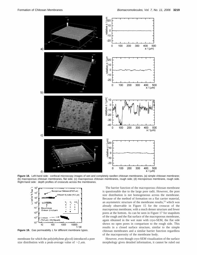
The barrier function of the macroporous chitosan membraneis questionable due to the large pore radii. However, the poresize distribution is not homogeneous across the membrane.Because of the method of formation on a flat carrier material,an asymmetric structure of the membrane results,53 which wasalready observable in Figure 15 for the crosscut of themacroporous membrane, with a much denser structure and fewerpores at the bottom. As can be seen in Figure 17 for snapshotsof the rough and the flat surface of the macroporous membrane,again obtained in the wet state with cryo-SEM, the flat sideshows no open pores in comparison to the rough side. Thisresults in a closed surface structure, similar to the simplechitosan membranes and a similar barrier function regardlessof the macroporosity of the membrane body.
However, even though cryo-SEM visualization of the surfacemorphology gives detailed information, it cannot be ruled out
Figure 18. Left-hand side: confocal microscopy images of wet and completely swollen chitosan membranes, (a) simple chitosan membrane;(b) macroporous chitosan membranes, flat side; (c) macroporous chitosan membranes, rough side; (d) microporous membrane, rough side.Right-hand side: depth profiles of crosscuts across the membranes.
Figure 19. Gas permeability L for different membrane types.
that the cryo-drying process alters the sample, especially thesensitive surface structure. A more accurate investigation of thesurface morphology in a truly wet state is possible with confocallaser microscopy that allows for a quantitative analysis of thepore sizes, depth, and therefore the determination of an openor closed surface. As one can see in Figure 18a from the depthprofile of a crosscut along the surface, the simple chitosanmembrane has a smooth and closed surface with a roughnessof ∼1 µm.
The flat side of the macroporous membrane, Figure 18b,shows a similar closed surface. However, due to the poresunderneath, the surface is more textured, as could already beobserved in the cryo-SEM pictures of Figure 17. The roughside of the macroporous membrane (c) shows, as expected, anopen pore structure with indentations deeper then the correlatedpore width. In contrast to this, the rough side of the microporousmembrane (d) shows a much smoother surface structure.
Both micro- and macroporous membranes need a reinforce-ment similar to that of the chitosan symplexes to show amechanical stability comparable to the pure chitosan membranesthat is sufficient to handle and apply the membranes. Examplesfor stress strain experiments are given in the final part of thediscussion.
3.2. Comparison of Membranes.The different types andalterations of chitosan membranes mentioned in this report allshow differences in permeability and strength due to variationsof the molecular parameters as molar mass, DDA (degree ofdeacetylation), etc., and those differences have been treated indetail in the above discussion. However, these property varia-tions are minor as compared to differences between varyingcross-linking mechanisms or different membranes. In thefollowing, we will therefore directly compare representativemembranes of the different approaches presented in this paperregarding their physical properties and their applicability as wetwound dressings.
Figure 19 gives a comparison of the gas permeability of thedifferent types of membranes. In this case, the permeability isdefined as the gas volumeV per timet that permeates throughan areaA of membrane for a pressure gradient∆p across themembrane:
It should be noted that for each type of membrane arepresentative average permeability range was selected forcomparison; the permeability of one type of membrane can againbe adjusted in a smaller range as discussed previously bychanging internal structural parameters such as network structureor pore size density. The permeabilities in Figure 19 are formembranes of different thicknesses. This representation isjustified because the shown thicknessesd represent typicalvalues for the application, obtained for the respective formationprocess of a membrane.
For a direct comparison of the material permeability, Figure20 gives the reduced permeabilityLred,
which is independent of the membrane thickness and dependsonly on the membrane structure. Obviously, the order ofmagnitude thinner symplex membranes have in this respect alower permeability, comparable to the macroporous membranes.Still, simple chitosan membranes show by far the least perme-ability for gases.
A comparison of the mechanical strength of the differentmembranes is given in Figure 21. It should first be noted thatthe stress-strain data of the weaker materials discussed previ-ously are given in this figure for cellulose reinforced membranes,because this is the only modification that can be used inapplications as wet wound dressings. The stability of nonrein-forced membranes, where available, was mentioned previously.Second, the stress data are referring to the whole membranecrosscut area to directly compare the actual material strengthof the membrane structures with the critical membrane param-eters introduced in Figure 6 for nonreinforced and in Figure 14for reinforced membranes.
However, this approach does not allow the separation of thestress contribution between the polymer membrane and thecellulose carrier material. For a weaker polymer membrane, thismay lead to weaker reduced stresses than for the pure cellulose,as was, for example, observed for the microporous membranein Figure 21. To give a better comparison of the mechanicalstrength of the different membrane types, we give in Figure 22the forceF per crosscut lengthw along the cellulose mesh bymultiplying the stress by the membrane thickness:
L ) VtA∆p
(10)
Lred ) Ld (11)
Figure 20. Reduced gas permeability Lred of oxygen for differentmembrane types.
Figure 21. Stress σ as a function of the applied strain ε for differentmembrane types.
Figure 22. Force F per crosscut length w for different membranetypes.
Fw
) σd (12)
3220 Biomacromolecules, Vol. 7, No. 11, 2006 Clasen et al.
This approach gives the mechanical strength for the typicalthickness of the reinforced membrane type. However, it shouldbe kept in mind that these values will change if the membranethickness is altered for systems where this is possible. It cannow clearly be seen that for mechanically weak polymermembrane components such as the symplex or microporousmembrane, the stability is mainly controlled by the strongerreinforcing cellulose mesh. For the case of a stronger polymercomponent (as compared to the cellulose mesh), as, for example,the pure chitosan, Figure 22 shows that the maximum sustain-able force is actually controlled by the polymer rather than thereinforcement.
4. Conclusions
The permeability and mechanical strength of chitosan mem-branes can be adjusted by several different methods.
The permeability of chitosan membranes can be increasedby swelling of the membrane with glycerol above a critical meshwidth. At the same time, the membrane becomes more flexibleand loses mechanical strength. An optimum mass ratio glycerol/chitosan of∼33% results in a membrane that just meets theempirically determined Young’s moduli and minimum requiredstresses for an application as a wound dressing.
An additional cross-linking of the chitosan with dialdehydesincreases the mechanical strength while keeping the Young’smodulus; however, the permeability is lowered significantly.The number density of cross-links correlates with the degreeof deacetylation (DDA), whereas an increasing length of thecross-linker leads to weaker network structures.
The formation of a symplex membrane via electrostaticinteraction of the chitosan with the anionic counterion sulfoethylcellulose leads to thin and highly permeable membranes.However, the mechanical strength of symplex membranes istoo low for a practical application. The symplex membrane canbe reinforced by a carrier material (cellulose mesh) to increasethe mechanical strength at roughly the same permeability. Thereinforced membranes show a pronounced resistance againstpunctual rupture and require a new set of empirical criticalYoung’s moduli and minimum stresses.
The permeability of a sufficiently strong chitosan membranecan be increased by introducing artificial pores. The introductionof inert particles or polymers during the membrane formationand the subsequent removal create macro- and microporousstructures with variable pore sizes in a range of 0.5-100 µmand superior gas and fluid transport capabilities. However, thesemembranes need reinforcement similar to the symplex mem-branes to reach the required mechanical strength for anapplication as a wound dressing. Because of the formationconditions, an asymmetric pore size distribution and closedsurface structure ensure the microbial barrier function even forthe macroporous membrane structures.
A comparison of the different reinforced chitosan membranetypes shows that they meet the minimum mechanical strengthsrequired, so that the permeability can be precisely adjusted tothe desired parameters of a certain wound type. For burns witha required moist wound climate but high exudate permeabilitiesaway from the wound with at the same time good antibacterialbarrier function, cross-linked macroporous membranes on acarrier material promise to be most suited as wet wounddressings. For chronic wounds with a required less moist climatebut a high gas exchange to avoid anaerobe conditions, reinforcedsymplex membranes are the most promising candidates fortailored wet wound dressings. Ongoing clinical studies of thesenew membrane types have to prove their applicability.
Already the single formation techniques to modify a mem-brane allow for novel ways to tune and alter a membrane toshow and enhance a specific material property. However, it isin particular the demonstrated possibility to join these techniquesto create truly unique membranes that combines the differentdesired material functions in an up to now unequaled way. Thesemembranes allow for a tailored adjustment of single parameterswhile at the same time the overall material properties aremaintained. Parts of these novel combined membrane alterationsand formation techniques are now covered by the patent DE102004047115.
Acknowledgment. We would like to thank Prof. J. Ko¨tz,Universitat Potsdam, for conducting the SEM measurements,and Dr. S. Wessel, Beiersdorf AG Hamburg, for the confocalmicroscopy imaging of the membranes. We would also like tothank the Bundesministerium fu¨r Bildung und Forschung forthe financial support under the project “Aerobe mikrobielleAufarbeitung von Shrimpschalenabfa¨llen und Produktion vonChitin als Vorstufe von Chitosan und technische Umsetzung(BMBF-05-203)”, and the “Arbeitsstelle fu¨r Wissens- undTechnologietransfer (AWITT)” and the Patentverwertungs-agentur of the City of Hamburg for their support.
References and Notes
(1) Winter, G. D.Nature1962, 193, 293-294.(2) Chung, L. Y.; Schmidt, R. J.; Hamlyn, P. F.; Sagar, B. F.; Andrews,
A. M.; Turner, T. D.J. Biomed. Mater. Res.1994, 28, 463-469.(3) Turner, T. D.J. Sterile SerV. Man. 1985, 2, 3-6.(4) Application: DE 93-43281904328190, Water-absorbing wound
dressing.(5) Martin, P.Science1997, 276, 75-81.(6) Alvarez, O. M.; Patel, M.; Booker, J.; Markowitz, L.Wounds-
(36) Larson, R. G.The Structure and Rheology of Complex Fluids; OxfordUniversity Press: New York, 1999.
(37) Clasen, C.; Kulicke, W. M.Prog. Polym. Sci.2001, 26, 1839-1919.(38) Peter, M. G.J. Macromol. Sci., Pure Appl. Chem.1995, A32, 629-
640.(39) Marreco, P. R.; da Luz Moreira, P.; Genari, S. C.; Moraes, A. M.J.
Biomed. Mater. Res., Part B2004, 71B, 268-277.(40) Liu, Y. L.; Su, Y. H.; Lai, J. Y.Polymer2004, 45, 6831-6837.(41) Liu, Y. L.; Su, Y. H.; Lee, K. R.; Lai, J. Y.J. Membr. Sci.2005,
251, 233-238.
(42) Tsuru, K.; Shirosaki, Y.; Hayakawa, S.; Osaka, A.; Lopes, M. A.;Santos, J. D.; Fernandes, M. H.Bioceramics, Vol. 17; Trans TechPublications Ltd.: Zurich-Uetikon, 2005; Vol. 17, pp 823-826.
(43) Gumusderelioglu, M.; Agi, P.React. Funct. Polym.2004, 61, 211-220.